EP1897842A2 - Premounting unit for operating an industrial truck - Google Patents
Premounting unit for operating an industrial truck Download PDFInfo
- Publication number
- EP1897842A2 EP1897842A2 EP07015655A EP07015655A EP1897842A2 EP 1897842 A2 EP1897842 A2 EP 1897842A2 EP 07015655 A EP07015655 A EP 07015655A EP 07015655 A EP07015655 A EP 07015655A EP 1897842 A2 EP1897842 A2 EP 1897842A2
- Authority
- EP
- European Patent Office
- Prior art keywords
- bearing
- assembly unit
- unit according
- frame
- attachment
- Prior art date
- Legal status (The legal status is an assumption and is not a legal conclusion. Google has not performed a legal analysis and makes no representation as to the accuracy of the status listed.)
- Granted
Links
- 230000005540 biological transmission Effects 0.000 claims 1
- 239000000725 suspension Substances 0.000 description 5
- 101100390736 Danio rerio fign gene Proteins 0.000 description 2
- 101100390738 Mus musculus Fign gene Proteins 0.000 description 2
- 238000010276 construction Methods 0.000 description 2
- 238000013459 approach Methods 0.000 description 1
- 238000005266 casting Methods 0.000 description 1
- 238000009434 installation Methods 0.000 description 1
- 230000013011 mating Effects 0.000 description 1
- 230000035939 shock Effects 0.000 description 1
Images


Classifications
-
- B—PERFORMING OPERATIONS; TRANSPORTING
- B66—HOISTING; LIFTING; HAULING
- B66F—HOISTING, LIFTING, HAULING OR PUSHING, NOT OTHERWISE PROVIDED FOR, e.g. DEVICES WHICH APPLY A LIFTING OR PUSHING FORCE DIRECTLY TO THE SURFACE OF A LOAD
- B66F9/00—Devices for lifting or lowering bulky or heavy goods for loading or unloading purposes
- B66F9/06—Devices for lifting or lowering bulky or heavy goods for loading or unloading purposes movable, with their loads, on wheels or the like, e.g. fork-lift trucks
- B66F9/075—Constructional features or details
- B66F9/07572—Propulsion arrangements
-
- B—PERFORMING OPERATIONS; TRANSPORTING
- B62—LAND VEHICLES FOR TRAVELLING OTHERWISE THAN ON RAILS
- B62B—HAND-PROPELLED VEHICLES, e.g. HAND CARTS OR PERAMBULATORS; SLEDGES
- B62B3/00—Hand carts having more than one axis carrying transport wheels; Steering devices therefor; Equipment therefor
- B62B3/04—Hand carts having more than one axis carrying transport wheels; Steering devices therefor; Equipment therefor involving means for grappling or securing in place objects to be carried; Loading or unloading equipment
- B62B3/06—Hand carts having more than one axis carrying transport wheels; Steering devices therefor; Equipment therefor involving means for grappling or securing in place objects to be carried; Loading or unloading equipment for simply clearing the load from the ground
- B62B3/0612—Hand carts having more than one axis carrying transport wheels; Steering devices therefor; Equipment therefor involving means for grappling or securing in place objects to be carried; Loading or unloading equipment for simply clearing the load from the ground power operated
-
- B—PERFORMING OPERATIONS; TRANSPORTING
- B62—LAND VEHICLES FOR TRAVELLING OTHERWISE THAN ON RAILS
- B62B—HAND-PROPELLED VEHICLES, e.g. HAND CARTS OR PERAMBULATORS; SLEDGES
- B62B2301/00—Wheel arrangements; Steering; Stability; Wheel suspension
- B62B2301/20—Resilient wheel suspension using springs
Definitions
- the invention relates to a pre-assembly unit for driving an industrial truck according to the preamble of patent claim 1.
- the drive wheel is often unsprung, with a certain spring effect on the tires. It is also known to suspend the drive wheel resiliently and possibly to load or relieve depending on the load.
- the invention has for its object to provide a pre-assembly for driving a truck, which allows independent of their concrete structure an optional connection with the frame of a truck.
- the structure should be compact, especially with resilient suspension of the drive wheel.
- At least one upper link of the parallel linkage is articulated to the lower end of a separate attachment section, which with attachment points forms an interface with a counter-attachment section on the frame.
- At least one spring is arranged between a shoulder of the bearing component and an abutment of the fastening portion below the fastening points.
- the attachment portion preferably has two in-plane flanges with attachment holes.
- the steering can be servo-assisted or operated directly by a drawbar.
- the pre-assembly can be connected to a pallet truck, a stacker or other truck and z. B. replace an unsprung drive unit.
- the frame of the truck is designed completely identical with regard to the attachment of the drive unit. Accordingly, various pre-assembly units (one set) have the same attachment portion regardless of their concrete design. Therefore, an embodiment of the invention also provides to provide a set of different pre-assembly, each having the same attachment portion for attachment to the frame of the truck.
- the attachment portion is integrally formed with a cylinder jacket of a lift cylinder whose piston rod on the load part an industrial truck attacks above the mounting portion.
- a pre-assembly is used for. B. as a drive for a pallet truck with spring-loaded drive wheel suspension.
- the bearing component is provided with two parallel spaced bearing lugs, between which an elongated member having an axial through-hole, e.g. a tube is arranged.
- the lower links of the parallel linkage are firmly connected to the component. Through its bore a bearing shaft is guided.
- One of the lower links is pivotally mounted on the inside of the bearing lug and the other on the outside of the other bearing lug.
- the assembly may be a welded assembly or a casting. It can also be easily prefabricated and then brought together with the bearing component.
- the first of the two lower links is on the other side of the associated bearing neck as the other link, so that the entire unit of the fifth wheel, bearing component and drive wheel of the lower linkage is released by simply moving sideways on the bearing shaft.
- installation and removal of the pre-assembly are extremely easy to do, even in confined spaces.
- the bearing member has an approximately centrally located between the lower bearing lugs upstanding bearing lug on which a single upper arm is articulated, which is articulated by a flange of the mounting portion, releasably connected to the mating mounting portion of the frame is connectable.
- This design limits the number of levers to three for the parallel guide. In this way, enough space is also created on each side of the upper bearing neck to arrange a spring, which are supported according to an embodiment of the invention at the lower end on an approximately horizontal plate-shaped portion of the first bearing component.
- the articulation of the upper single lever is preferably such that it also allows the sideways movement of the entire drive unit for release in the frame.
- an embodiment of the invention provides that the axes of the lower arm of the parallel linkage and the articulation of the lever on the frame are coaxial.
- the levers are pivotally mounted on the bearing shaft. In this way, a simple and compact construction for the suspension of the drive wheel is achieved.
- a low-lift truck is partially shown. It has a drive part and a load part.
- the drive part is shown only with a frame 100 and a drive unit 10.
- the drive unit 10 will be described below with reference to Figures 2 to 6 in more detail.
- a load part 102 has two parallel wheel arms 104, 106. Furthermore, a battery receptacle can be seen, which is firmly connected to the radar arms 104, 106. These should not be discussed further.
- the drawn up portion of the battery receptacle, which is designated by 108, is, as will be shown, connected to the lifting cylinder of the drive member 10.
- a three-armed lever 110 is pivotally mounted at 112 on the load part 102 about a horizontal axis. On the opposite side a corresponding lever is provided. One arm of the lever 110 is pivotally hinged to the frame 100 at 114. A third arm of the lever is hinged at 116 to a push rod which is guided within the Radarms 106. The same applies to the wheel arm 104. At the end of the wheel arms 104, 106 are load wheels (not shown), which are mounted in a rocker, which is connected to the respective push rod. If the load part 102 is raised, the lever 110 pivots in the clockwise direction and thereby exerts a pressure on the push rod. This kinematics is well known in low-lift trucks.
- the drive unit 10 is shown in more detail.
- the truck is a tricycle. It may be a common handlebar or drawbar steered truck also with a four-wheel or Jardinradfahrwerk.
- a drive wheel 12 is rotatably mounted about a horizontal axis in a turntable 14 about a horizontal axis.
- the turntable 14 has an angle gear 16 and an upper horizontal sprocket 18, on which a drive motor 20 is mounted.
- the drive motor 20 may be a three-phase motor or else a DC motor, which sets the drive wheel 12 in rotation via the gear 16.
- the ring gear 18 is rotatably mounted in a bearing member 22 about a vertical axis. On the upper side of the bearing member 22 sits upright a steering motor 24 which rotates the turntable 14 about the vertical axis when it is driven in accordance with a steering sensor.
- the described components are conventional and therefore need not be further discussed in detail.
- the bearing component 22 has an upper horizontal portion and an apron 26 extending differently far down therefrom, which is partly formed in a circular arc shape. However, it is partially open at the rear and forms below the disc 18 a horizontal paragraph 28 from. From this are stock approaches 30, 32 down. They are approximately parallel and at a distance from each other. As shown in Figs. shows, 32 relatively short arms are hinged to the bearing lugs 30, 32. At the bearing shoulder 30, a link 34 and the bearing lug 32, a link 36 is articulated. The link 36 is articulated on the outside of the bearing shoulder 32 and the handlebar 34 on the inside of the bearing shoulder 30. The articulation via pivot in corresponding holes of the bearing lugs 30, 32, which is not shown in detail. Only in Fig. 2 and 6, a bearing pin can be seen at 38.
- the links 34, 36 are welded to a tube 40. With the tube they form a unit. Through the pipe a bearing rod or shaft 42 is inserted, which is mounted on the frame 100 of the truck (Fig. 1).
- an upper bearing shoulder 44 is mounted on the back of the drive motor 20, which is arranged approximately in the middle between the lower bearing lugs 30, 32.
- a single upper link 46 is articulated, which is hinged at the other end to a lower projection 48 of a mounting portion 50.
- the links 34, 36 and 46, the bearing lugs 30, 32 and the attachment portion 50 thus form a parallelogram linkage, which allows an approximately vertical movement of the drive unit 10.
- the mounting portion 50 has on opposite sides of a one-piece molded jacket of a lift cylinder 52 in-plane mounting flanges 54, 56 with two mounting holes for attachment to a wall portion of the vehicle frame 100.
- a flange 58 is attached for the purpose of connection with the load part 102 of the truck.
- the bearing pin with the bearing lugs 30, 32 disengage. If the bearing rod 42 is pulled out of the tube 40, the drive unit is free and can be removed. This is possible naturally only if previously the attachment of the flanges 54, 56 has been solved on the frame.
- the lower arm 34, 36 are mounted on the frame 100 of the drive member on the same axis as the one arm of the lever 110 for the Hubgestfite. In this way, the construction cost is kept very low and the drive unit made compact.
Abstract
Description
Die Erfindung bezieht sich auf eine Vormontageeinheit für den Antrieb eines Flurförderzeugs nach dem Oberbegriff des Patentanspruchs 1.The invention relates to a pre-assembly unit for driving an industrial truck according to the preamble of patent claim 1.
Unabhängig davon, ob Flurförderzeuge ein Dreiradfahrwerk, Vierradfahrwerk oder Fünfradfahrwerk aufweisen, ist zumeist nur ein einziges Antriebsrad vorgesehen, das in den meisten Fällen auch gleichzeitig gelenktes Rad ist. Zu diesem Zweck ist das Antriebsrad in einem sogenannten Drehschemel um eine horizontale Welle drehbar gelagert, welcher in einem zweiten Lagerbauteil um eine vertikale Welle drehbar gelagert ist. Mit Hilfe eines Lenkantriebs wird der Drehschemel relativ zum rahmenfesten oder nicht drehbaren Lagerbauteil verschwenkt. Am Drehschemel sitzt ein Antriebsmotor, der mit verschwenkt wird und der etwa über ein Kegelrad- oder Stirnradgetriebe das Antriebsrad antreibt.Regardless of whether trucks have a tricycle landing gear, four-wheel drive or Fünfradfahrwerk, usually only a single drive wheel is provided, which is also simultaneously steered wheel in most cases. For this purpose, the drive wheel is rotatably mounted in a so-called turntable about a horizontal shaft, which is rotatably mounted in a second bearing member about a vertical shaft. With the help of a steering drive of the fifth wheel is pivoted relative to the frame-fixed or non-rotatable bearing component. On the fifth wheel sits a drive motor, which is pivoted with and drives the drive wheel via a bevel gear or spur gear, for example.
Das Antriebsrad ist häufig ungefedert, wobei eine gewisse federnde Wirkung über die Bereifung erfolgt. Es ist auch bekannt, das Antriebsrad federnd aufzuhängen und ggf. in Abhängigkeit von der Last zu be- oder entlasten.The drive wheel is often unsprung, with a certain spring effect on the tires. It is also known to suspend the drive wheel resiliently and possibly to load or relieve depending on the load.
Bei Mitfahr-Flurförderzeugen ist die federnde Aufhängung des Antriebsrads erwünscht, damit der Fahrer nicht starken Stößen ausgesetzt ist. Aus
Der Erfindung liegt die Aufgabe zugrunde, eine Vormontageeinheit für den Antrieb eines Flurförderzeugs zu schaffen, die unabhängig von ihrem konkreten Aufbau eine wahlweise Verbindung mit dem Rahmen eines FFZ ermöglicht. Der Aufbau soll kompakt sein, insbesondere bei federnder Aufhängung des Antriebsrades.The invention has for its object to provide a pre-assembly for driving a truck, which allows independent of their concrete structure an optional connection with the frame of a truck. The structure should be compact, especially with resilient suspension of the drive wheel.
Diese Aufgabe wird durch die Merkmale des Patentanspruchs 1 gelöst.This object is solved by the features of patent claim 1.
Bei der erfindungsgemäßen Vormontageeinheit ist mindestens ein oberer Lenker des Parallelgestänges am unteren Ende eines getrennten Befestigungsabschnitts angelenkt, der mit Befestigungsstellen eine Schnittstelle mit einem Gegenbefestigungsabschnitt am Rahmen bildet. Mindestens eine Feder ist zwischen einem Absatz des Lagerbauteils und einem Widerlager des Befestigungsabschnitts unterhalb der Befestigungsstellen angeordnet. Der Befestigungsabschnitt weist vorzugsweise zwei in einer Ebene liegende Flanschen auf mit Befestigungslöchern.In the preassembly unit according to the invention, at least one upper link of the parallel linkage is articulated to the lower end of a separate attachment section, which with attachment points forms an interface with a counter-attachment section on the frame. At least one spring is arranged between a shoulder of the bearing component and an abutment of the fastening portion below the fastening points. The attachment portion preferably has two in-plane flanges with attachment holes.
Abgesehen von feststehenden Vorgaben für die Vormontageeinheit kann diese beliebig ausgelegt sein. Die Lenkung kann servounterstützt sein oder von einer Deichsel direkt betätigt werden. Die Vormontageeinheit kann mit einem Niederhubwagen, einem Hochhubwagen oder einem sonstigen Flurförderzeug verbunden werden und z. B. eine ungefederte Antriebseinheit ersetzen. Der Rahmen des Flurförderzeugs ist im Hinblick auf die Anbringung der Antriebseinheit völlig gleich gestaltet. Entsprechend weisen verschiedene Vormontageeinheiten (ein Satz) den gleichen Befestigungsabschnitt auf unabhängig von ihrer konkreten Ausführung. Daher sieht eine Ausgestaltung der Erfindung auch vor, einen Satz unterschiedlicher Vormontageeinheiten vorzusehen, die jeweils den gleichen Befestigungsabschnitt aufweisen zur Anbringung am Rahmen des Flurförderzeugs.Apart from fixed specifications for the pre-assembly, this can be designed arbitrarily. The steering can be servo-assisted or operated directly by a drawbar. The pre-assembly can be connected to a pallet truck, a stacker or other truck and z. B. replace an unsprung drive unit. The frame of the truck is designed completely identical with regard to the attachment of the drive unit. Accordingly, various pre-assembly units (one set) have the same attachment portion regardless of their concrete design. Therefore, an embodiment of the invention also provides to provide a set of different pre-assembly, each having the same attachment portion for attachment to the frame of the truck.
Nach einer Ausgestaltung der Erfindung ist der Befestigungsabschnitt einteilig mit einem Zylindermantel eines Hubzylinders geformt, dessen Kolbenstange am Lastteil eine Flurförderzeugs oberhalb des Befestigungsabschnitts angreift. Eine derartige Vormontageeinheit dient z. B. als Antrieb für einen Niederhubwagen mit gefederter Antriebsradaufhängung.According to one embodiment of the invention, the attachment portion is integrally formed with a cylinder jacket of a lift cylinder whose piston rod on the load part an industrial truck attacks above the mounting portion. Such a pre-assembly is used for. B. as a drive for a pallet truck with spring-loaded drive wheel suspension.
Nach einer weiteren Ausgestaltung der Erfindung ist das Lagerbauteil mit zwei parallel beabstandeten Lageransätzen versehen, zwischen denen ein längliches, eine axiale Durchbohrung aufweisendes Bauteil, z.B. ein Rohr, angeordnet ist. Die unteren Lenker des Parallelgestänges sind fest mit dem Bauteil verbunden. Durch seine Bohrung ist eine Lagerwelle hindurch geführt. Einer der unteren Lenker ist an der Innenseite des Lageransatzes und der andere an der Außenseite des anderen Lageransatzes schwenkbar gelagert. Bei einer derartigen Lagerung bilden die unteren Lenker und das zwischen diesen angebrachte Bauteil eine Baueinheit, die eine stabile Vertikalführung des Antriebsrades bei Schwingungen ermöglicht. Die Baueinheit kann eine Schweißbaugrupe oder auch ein Gußteil sein. Sie kann außerdem auf einfache Weise vorgefertigt und anschließend mit dem Lagerbauteil zusammengebracht werden. Denn der erste der beiden unteren Lenker liegt auf der anderen Seite des zugeordneten Lageransatzes wie der andere Lenker, so daß durch einfach seitliches Verschieben auf der Lagerwelle die gesamte Einheit aus Drehschemel, Lagerbauteil und Antriebsrad von der unteren Anlenkung freikommt. Somit sind Ein- und Ausbau der Vormontageeinheit äußerst einfach zu bewerkstelligen, auch bei beengten räumlichen Verhältnissen.According to a further embodiment of the invention, the bearing component is provided with two parallel spaced bearing lugs, between which an elongated member having an axial through-hole, e.g. a tube is arranged. The lower links of the parallel linkage are firmly connected to the component. Through its bore a bearing shaft is guided. One of the lower links is pivotally mounted on the inside of the bearing lug and the other on the outside of the other bearing lug. In such a storage form the lower arm and the component mounted between them a unit that allows a stable vertical guidance of the drive wheel in vibration. The assembly may be a welded assembly or a casting. It can also be easily prefabricated and then brought together with the bearing component. Because the first of the two lower links is on the other side of the associated bearing neck as the other link, so that the entire unit of the fifth wheel, bearing component and drive wheel of the lower linkage is released by simply moving sideways on the bearing shaft. Thus, installation and removal of the pre-assembly are extremely easy to do, even in confined spaces.
Nach einer Ausgestaltung der Erfindung ist vorgesehen, daß das Lagerbauteil einen annähernd mittig zwischen den unteren Lageransätzen nach oben stehenden Lageransatz aufweist, an dem ein einziger oberer Lenker angelenkt ist, der seitens einem einen Flansch des Befestigungsabschnitts angelenkt ist, der lösbar mit dem Gegenbefestigungsabschnitt des Rahmens verbindbar ist. Diese Konstruktion beschränkt für die Parallelführung die Anzahl der Hebel auf drei. Auf diese Weise ist auch ausreichend Raum geschaffen, um auf jeder Seite des oberen Lageransatzes eine Feder anzuordnen, die sich nach einer Ausgestaltung der Erfindung an dem unteren Ende auf einem annähernd horizontalen plattenförmigen Abschnitt des ersten Lagerbauteils abstützen. Die Anlenkung des oberen einzigen Hebels ist vorzugsweise derart, daß er ebenfalls die Seitwärtsbewegung der gesamten Antriebseinheit zum Lösen im Rahmen erlaubt.According to one embodiment of the invention, it is provided that the bearing member has an approximately centrally located between the lower bearing lugs upstanding bearing lug on which a single upper arm is articulated, which is articulated by a flange of the mounting portion, releasably connected to the mating mounting portion of the frame is connectable. This design limits the number of levers to three for the parallel guide. In this way, enough space is also created on each side of the upper bearing neck to arrange a spring, which are supported according to an embodiment of the invention at the lower end on an approximately horizontal plate-shaped portion of the first bearing component. The articulation of the upper single lever is preferably such that it also allows the sideways movement of the entire drive unit for release in the frame.
Für Niederhub-Flurförderzeug ist bekannt, die Lasträder, die am vorderen Ende von Lastarmen gelagert sind, über ein Zug- oder Druckgestänge zu betätigen. Das Gestänge ist an einem mehrarmigen Hebel angelenkt, der seinerseits am Lastteil drehbar gelagert ist. Ein weiterer Arm des Hebels ist am Rahmens des Antriebsteils angelenkt. Wird mit Hilfe des Hubzylinders das Lastteil angehoben, führt dies gleichzeitig zu einer Schwenkung des Hebels, der auf das Gestänge zu den Lasträdern hinein wirkt und diese gegenüber den Lastarmen nach unten verschwenkt, so daß die Lastarme parallel zu sich selbst und am vorderen Ende gleichfalls unterstützt angehoben werden können. In diesem Zusammenhang sieht eine Ausgestaltung der Erfindung vor, daß die Achsen der unteren Lenker des Parallelgestänges und der Anlenkung der Hebel am Rahmen koaxial sind. Vorzugsweise sind die Hebel auf der Lagerwelle schwenkbar gelagert. Auf diese Weise wird eine einfache und kompakte Konstruktion für die Aufhängung des Antriebsrades erreicht.For low-lift truck is known to operate the load wheels, which are mounted at the front end of load arms, via a pull or push rod. The linkage is articulated on a multi-armed lever, which in turn is rotatably mounted on the load part. Another arm of the lever is hinged to the frame of the drive part. If the load part is raised with the aid of the lifting cylinder, this simultaneously leads to a pivoting of the lever which acts on the linkage to the load wheels and pivots them downwards relative to the load arms so that the load arms also support parallel to themselves and at the front end can be raised. In this context, an embodiment of the invention provides that the axes of the lower arm of the parallel linkage and the articulation of the lever on the frame are coaxial. Preferably, the levers are pivotally mounted on the bearing shaft. In this way, a simple and compact construction for the suspension of the drive wheel is achieved.
Die Erfindung wird nachfolgend anhand eines in Zeichnungen dargestellten Ausführungsbeispiels näher erläutert.
- Fig. 1
- zeigt perspektivisch eine Vormontageeinheit nach der Erfindung in einem Niederhub-Flurförderzeug.
- Fig. 2
- zeigt die Seitenansicht rechts der Vormontageeinheit nach Fig. 1.
- Fig. 3
- zeigt die Vorderansicht der Vormontageeinheit nach Fig. 2.
- Fig. 4
- zeigt die Seitenansicht links der Vormontageeinheit nach Fig. 2.
- Fig. 5
- zeigt die Draufsicht auf die Vormontageeinheit nach Fig. 2.
- Fig. 6
- zeigt perspektivisch die Vormontageeinheit nach den Fign. 2 bis 4.
- Fig. 1
- shows in perspective a pre-assembly according to the invention in a low-lift truck.
- Fig. 2
- shows the side view on the right of the pre-assembly according to FIG. 1.
- Fig. 3
- shows the front view of the pre-assembly according to FIG. 2.
- Fig. 4
- shows the side view left of the pre-assembly according to FIG. 2.
- Fig. 5
- shows the top view of the pre-assembly according to FIG. 2.
- Fig. 6
- shows in perspective the pre-assembly according to FIGS. 2 to 4.
In Figur 1 ist ein Niederhub-Flurförderzeug teilweise dargestellt. Es weist ein Antriebsteil und ein Lastteil auf. Das Antriebsteil ist lediglich mit einem Rahmen 100 sowie einer Antriebseinheit 10 dargestellt. Die Antriebseinheit 10 wird weiter unten anhand der Figuren 2 bis 6 näher beschrieben.In Figure 1, a low-lift truck is partially shown. It has a drive part and a load part. The drive part is shown only with a
Ein Lastteil 102 weist zwei parallele Radarme 104, 106 auf. Ferner ist eine Batterieaufnahme zu erkennen, die fest mit den Radarmen 104, 106 verbunden ist. Auf diese soll nicht weiter eingegangen werden. Der nach oben gezogene Teil der Batterieaufnahme, der mit 108 bezeichnet ist, ist, wie noch gezeigt wird, mit dem Hubzylinder des Antriebsteils 10 verbunden.A
Ein dreiarmiger Hebel 110 ist bei 112 schwenkbar am Lastteil 102 um eine horizontale Achse gelagert. Auf der gegenüberliegende Seite ist ein entsprechender Hebel vorgesehen. Ein Arm des Hebels 110 ist bei 114 schwenkbar am Rahmen 100 angelenkt. Ein dritter Arm des Hebels ist bei 116 an einer Druckstange angelenkt, welche innerhalb des Radarms 106 geführt ist. Das gleiche gilt für den Radarm 104. Am Ende der Radarme 104, 106 finden sich Lasträder (nicht gezeigt), die in einer Schwinge gelagert sind, welche mit der jeweiligen Druckstange verbunden ist. Wird das Lastteil 102 angehoben, verschwenkt der Hebel 110 in Uhrzeigerrichtung und übt dadurch einen Druck auf die Druckstange aus. Diese Kinematik ist bei Niederhub-Flurförderzeugen allgemein bekannt.A three-
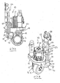
In den Fign. 2 bis 6 ist die Antriebseinheit 10 näher dargestellt. In Fig. 1 ist das Flurförderzeug ein Dreiradfahrzeug. Es kann ein übliches lenker- oder deichselgelenktes Flurförderzeug sein auch mit einem Vierrad- oder Fünfradfahrwerk.In the Fign. 2 to 6, the
Ein Antriebsrad 12 ist um eine horizontale Achse in einem Drehschemel 14 um eine horizontale Achse drehbar gelagert. Der Drehschemel 14 weist ein Winkelgetriebe 16 auf sowie einen oberen horizontalen Zahnkranz 18, auf dem ein Antriebsmotor 20 angebracht ist. Der Antriebsmotor 20 kann ein Drehstrommotor sein oder auch ein Gleichstrommotor, der über das Getriebe 16 das Antriebsrad 12 in Drehung versetzt. Der Zahnkranz 18 ist in einem Lagerbauteil 22 um eine vertikale Achse drehbar gelagert. Auf der Oberseite des Lagerbauteils 22 sitzt aufrecht ein Lenkmotor 24, der den Drehschemel 14 um die vertikale Achse verdreht, wenn er entsprechend über einen Lenkgeber angesteuert wird. Die beschriebenen Bauteile sind konventionell und müssen daher im einzelnen nicht weiter erörtert werden.A
Wie aus den Figuren hervorgeht, weist das Lagerbauteil 22 einen oberen horizontalen Abschnitt und eine von diesen sich unterschiedlich weit nach unten erstreckende Schürze 26 auf, welche teils kreisbogenförmig geformt ist. Sie ist jedoch an der Hinterseite teilweise offen und bildet dort unterhalb der Scheibe 18 einen horizontalen Absatz 28 aus. Von diesem stehen Lageransätze 30, 32 nach unten. Sie sind annähernd parallel und im Abstand zueinander. Wie aus den Fign. hervorgeht, sind an den Lageransätzen 30, 32 relativ kurze Lenker angelenkt. Am Lageransatz 30 ist ein Lenker 34 und am Lageransatz 32 ein Lenker 36 angelenkt. Der Lenker 36 ist an der Außenseite des Lageransatzes 32 angelenkt und der Lenker 34 an der Innenseite des Lageransatzes 30. Die Anlenkung erfolgt über Drehzapfen in entsprechenden Bohrungen der Lageransätze 30, 32, die im einzelnen nicht dargestellt ist. Lediglich in Fig. 2 und 6 läßt sich ein Lagerzapfen bei 38 erkennen.As can be seen from the figures, the bearing
Die Lenker 34, 36 sind mit einem Rohr 40 verschweißt. Mit dem Rohr bilden sie eine Einheit. Durch das Rohr ist eine Lagerstange oder -welle 42 hindurchgesteckt, die am Rahmen 100 des Flurförderzeugs angebracht ist (Fig. 1).The
Auf der Oberseite des Lagerbauteils 22 ist auf der Rückseite des Antriebsmotors 20 ein oberer Lageransatz 44 angebracht, der annähernd in der Mitte zwischen den unteren Lageransätzen 30, 32 angeordnet ist. An dem Lageransatz 44 ist ein einziger oberer Lenker 46 angelenkt, der am anderen Ende an einem unteren Ansatz 48 eines Befestigungsabschnitt 50 angelenkt ist. Die Lenker 34, 36 und 46, die Lageransätze 30, 32 und der Befestigungsabschnitt 50 bilden mithin ein Parallelogrammgestänge, das eine annähernd vertikale Bewegung der Antriebseinheit 10 ermöglicht.On the upper side of the bearing
Der Befestigungsabschnitt 50 weist auf gegenüberliegenden Seiten eines damit einteilig geformten Mantels eines Hubzylinders 52 in einer Ebene liegende Befestigungsflansche 54, 56 auf mit jeweils zwei Befestigungslöchern zur Anbringung an einem Wandabschnitt des Fahrzeugrahmens 100. An der Kolbenstange des Hubzylinders 52 ist eine Flanschplatte 58 angebracht zwecks Verbindung mit dem Lastteil 102 des Flurförderzeugs.The mounting
Unterhalb der Flansche 54, 56 sind scheibenförmige Widerlager 60, 62 für Federn 64, 66 angeordnet. Die Federn 64, 66 stützen sich am unteren Ende auf einem Plattenabschnitt des Absatzes 28 ab.Below the
Für die Demontage der Antriebseinheit 10 ist lediglich erforderlich, mit einer geringen Seitwärtsbewegung der Antriebseinheit 10 die Lagerzapfen mit den Lageransätzen 30, 32 außer Eingriff zu bringen. Wird die Lagerstange 42 aus dem Rohr 40 herausgezogen, ist die Antriebseinheit frei und kann entfernt werden. Dies geht naturgemäß nur, wenn zuvor die Befestigung der Flansche 54, 56 am Rahmen gelöst worden ist.For disassembly of the
Wie insbesondere aus Figur 1 hervorgeht, sind die unteren Lenker 34, 36 am Rahmen 100 des Antriebsteils auf der gleichen Achse gelagert wie der eine Arm des Hebels 110 für das Hubgestänge. Auf diese Weise ist der Bauaufwand sehr gering gehalten sowie die Antriebseinheit kompakt ausgeführt.As can be seen in particular from Figure 1, the
Claims (12)
Applications Claiming Priority (1)
| Application Number | Priority Date | Filing Date | Title |
|---|---|---|---|
| DE102006041684A DE102006041684A1 (en) | 2006-09-06 | 2006-09-06 | Pre-assembly unit for driving a truck |
Publications (3)
| Publication Number | Publication Date |
|---|---|
| EP1897842A2 true EP1897842A2 (en) | 2008-03-12 |
| EP1897842A3 EP1897842A3 (en) | 2009-05-06 |
| EP1897842B1 EP1897842B1 (en) | 2010-07-14 |
Family
ID=38683476
Family Applications (1)
| Application Number | Title | Priority Date | Filing Date |
|---|---|---|---|
| EP07015655A Active EP1897842B1 (en) | 2006-09-06 | 2007-08-09 | Premounting unit for operating an industrial truck |
Country Status (5)
| Country | Link |
|---|---|
| US (1) | US7854280B2 (en) |
| EP (1) | EP1897842B1 (en) |
| CN (1) | CN101138946B (en) |
| DE (2) | DE102006041684A1 (en) |
| ES (1) | ES2344809T3 (en) |
Cited By (2)
| Publication number | Priority date | Publication date | Assignee | Title |
|---|---|---|---|---|
| EP2284118A3 (en) * | 2009-08-14 | 2011-12-21 | Jungheinrich Aktiengesellschaft | Drive mount for rotatable mounting of a drive unit of an industrial truck |
| EP3470297A1 (en) * | 2017-10-10 | 2019-04-17 | UniCarriers Europe AB | A drive unit for an industrial truck and an industrial truck with such a drive unit |
Families Citing this family (15)
| Publication number | Priority date | Publication date | Assignee | Title |
|---|---|---|---|---|
| US9623891B2 (en) | 2011-04-19 | 2017-04-18 | Power Handling, Incorporated | Pallet jack power assembly |
| US8752657B2 (en) * | 2011-04-19 | 2014-06-17 | Power Handling, Incorporated | Pallet jack power assembly |
| CN103640446B (en) * | 2013-11-28 | 2016-08-17 | 苏州先锋物流装备科技有限公司 | A kind of drive installation shock mitigation system |
| CN104003330B (en) * | 2014-05-29 | 2017-01-11 | 诺力机械股份有限公司 | Truck |
| CN104401199A (en) * | 2014-11-28 | 2015-03-11 | 浙江上加机械有限公司 | Vibration-proofing bracket for electronic assisting steering driving assembly |
| CN104925695B (en) * | 2015-06-25 | 2018-01-30 | 重庆川渝精工机械配件开发有限公司 | A kind of damping tray truck |
| CN106672853B (en) * | 2015-11-06 | 2019-02-19 | 湖南南车时代电动汽车股份有限公司 | A kind of full-bearing type car power assembly assembly method and tooling |
| CN105459746B (en) * | 2015-11-09 | 2020-01-17 | 邱圣渊 | Independent rear suspension device of vehicle |
| CN105417440A (en) * | 2015-11-20 | 2016-03-23 | 安徽依诺玛智能科技有限公司 | Vertical type driving mechanism for laser-guiding automatic guided vehicle (AGV) forklift |
| CN105752886B (en) * | 2016-02-05 | 2020-12-04 | 广东嘉腾机器人自动化有限公司 | Forklift driven gear train capable of adapting to ground |
| CN106314032B (en) * | 2016-09-30 | 2018-10-26 | 宁波介量机器人技术有限公司 | A kind of linear commutation supporting roller |
| CN108069366A (en) * | 2016-11-15 | 2018-05-25 | 比亚迪股份有限公司 | A kind of vehicle and its steering structure |
| CN108407547A (en) * | 2018-04-26 | 2018-08-17 | 深圳市爱途仕智能科技有限公司 | Electronic universal wheel |
| CN110834494B (en) * | 2018-08-17 | 2023-01-20 | 深圳创维数字技术有限公司 | Universal wheel and carrier with same |
| US10946884B2 (en) * | 2019-06-20 | 2021-03-16 | Larry Simpson | Pneumatic cylinder actuated pallet jack assembly |
Citations (4)
| Publication number | Priority date | Publication date | Assignee | Title |
|---|---|---|---|---|
| EP0209502A2 (en) * | 1985-07-08 | 1987-01-21 | BT Industries Aktiebolag | An arrangement in industrial trucks |
| EP0383254A2 (en) * | 1989-02-17 | 1990-08-22 | Wagner Fördertechnik GmbH & Co KG | Lift-truck with a vertically spring-preloaded drive unit |
| GB2293363A (en) * | 1994-09-26 | 1996-03-27 | Linde Ag | Lift Truck |
| US6488297B2 (en) * | 2000-01-14 | 2002-12-03 | Kabushiki Kaisha Toyoda Jidoshokki Seisakusho | Suspension device of industrial vehicle |
Family Cites Families (16)
| Publication number | Priority date | Publication date | Assignee | Title |
|---|---|---|---|---|
| US2359493A (en) * | 1941-07-03 | 1944-10-03 | Irvin F Schreck | Lift truck |
| US2417394A (en) * | 1942-12-17 | 1947-03-11 | Yale & Towne Mfg Co | Lift truck |
| US2370866A (en) * | 1943-07-05 | 1945-03-06 | Salsbury Corp | Industrial truck |
| US2598151A (en) * | 1949-09-29 | 1952-05-27 | Market Forge Co | Lift truck |
| US3249170A (en) * | 1963-11-07 | 1966-05-03 | Yale & Towne Inc | Motorized lift truck |
| US3515233A (en) * | 1968-05-08 | 1970-06-02 | Crown Controls Corp | Articulated industrial truck |
| DE3420146C2 (en) * | 1984-05-30 | 1986-11-27 | Carl Hurth Maschinen- und Zahnradfabrik GmbH & Co, 8000 München | Steering chain connection |
| IT208008Z2 (en) * | 1986-07-15 | 1988-03-31 | Pezzolato Off Constr Mecc Spa | VEHICLE FOR REMOTE HANDLING OF LOADS |
| US4754837A (en) * | 1987-04-30 | 1988-07-05 | The Raymond Corporation | Lift truck steering apparatus |
| FR2626535B1 (en) * | 1988-01-29 | 1991-08-16 | Mic Sa | TRUCK |
| WO1994022761A1 (en) * | 1993-04-01 | 1994-10-13 | Dalnevostochnaya Gosudarstvennaya Morskaya Akademia Imeni Admirala G.I.Nevelskogo | Loader |
| DE4342944C2 (en) * | 1993-12-16 | 1996-05-23 | Jungheinrich Ag | Industrial truck |
| US5820163A (en) * | 1996-07-08 | 1998-10-13 | Ford Global Technologies, Inc. | Tilting, telescoping and energy absorbing steering column |
| CN2485286Y (en) * | 2001-05-30 | 2002-04-10 | 李文清 | Platform carrier |
| DE10221311B4 (en) * | 2002-05-14 | 2004-09-09 | Jungheinrich Ag | Low level truck |
| US7267349B2 (en) * | 2004-09-03 | 2007-09-11 | Beech Engineering & Manufacturing | Material handling lift vehicle and suspension system for use therewith |
-
2006
- 2006-09-06 DE DE102006041684A patent/DE102006041684A1/en not_active Withdrawn
-
2007
- 2007-08-09 EP EP07015655A patent/EP1897842B1/en active Active
- 2007-08-09 DE DE502007004375T patent/DE502007004375D1/en active Active
- 2007-08-09 ES ES07015655T patent/ES2344809T3/en active Active
- 2007-08-30 US US11/847,583 patent/US7854280B2/en active Active
- 2007-09-05 CN CN2007101497882A patent/CN101138946B/en active Active
Patent Citations (4)
| Publication number | Priority date | Publication date | Assignee | Title |
|---|---|---|---|---|
| EP0209502A2 (en) * | 1985-07-08 | 1987-01-21 | BT Industries Aktiebolag | An arrangement in industrial trucks |
| EP0383254A2 (en) * | 1989-02-17 | 1990-08-22 | Wagner Fördertechnik GmbH & Co KG | Lift-truck with a vertically spring-preloaded drive unit |
| GB2293363A (en) * | 1994-09-26 | 1996-03-27 | Linde Ag | Lift Truck |
| US6488297B2 (en) * | 2000-01-14 | 2002-12-03 | Kabushiki Kaisha Toyoda Jidoshokki Seisakusho | Suspension device of industrial vehicle |
Cited By (2)
| Publication number | Priority date | Publication date | Assignee | Title |
|---|---|---|---|---|
| EP2284118A3 (en) * | 2009-08-14 | 2011-12-21 | Jungheinrich Aktiengesellschaft | Drive mount for rotatable mounting of a drive unit of an industrial truck |
| EP3470297A1 (en) * | 2017-10-10 | 2019-04-17 | UniCarriers Europe AB | A drive unit for an industrial truck and an industrial truck with such a drive unit |
Also Published As
| Publication number | Publication date |
|---|---|
| DE502007004375D1 (en) | 2010-08-26 |
| CN101138946B (en) | 2010-12-08 |
| EP1897842B1 (en) | 2010-07-14 |
| EP1897842A3 (en) | 2009-05-06 |
| US7854280B2 (en) | 2010-12-21 |
| ES2344809T3 (en) | 2010-09-07 |
| US20080053744A1 (en) | 2008-03-06 |
| CN101138946A (en) | 2008-03-12 |
| DE102006041684A1 (en) | 2008-03-27 |
Similar Documents
| Publication | Publication Date | Title |
|---|---|---|
| EP1897842B1 (en) | Premounting unit for operating an industrial truck | |
| EP1808402B1 (en) | Pallet truck | |
| DE60130725T2 (en) | FORKLIFT WITH LOWER TURNING ADIUS AND MEANS FOR SIMPLIFYING MAINTENANCE WORK | |
| EP2956315B1 (en) | Wheel suspension for a motor vehicle | |
| DE2318048C3 (en) | Pallet truck | |
| EP0808747A1 (en) | Loading tailgate system | |
| DE19935008B4 (en) | Pallet truck | |
| DE602004007935T2 (en) | STEERING WHEEL STEERING SYSTEM | |
| EP1932799B1 (en) | Industrial truck | |
| EP2042410B1 (en) | Agricultural vehicle | |
| EP0332037B1 (en) | Axle lifting device | |
| EP2065334A1 (en) | Tipping mechanism for a lifting frame of an industrial truck and transport method of an industrial truck | |
| EP1541412A1 (en) | Loading tailboard system | |
| EP2066538B1 (en) | Rollover wash unit and method for mounting a rollover wash unit | |
| EP0955230B1 (en) | Working vehicle with tilting operator platform and lifting mechanism | |
| EP0557763B1 (en) | Road milling machine | |
| EP0133637B1 (en) | Front implement hitch device for a front covered vehicle for use in agriculture and/or the building industry, in particular for a farming tractor | |
| EP1500525B1 (en) | Rigid axle for a vehicle, in particular a leading or trailing retractable axle for trucks or busses | |
| EP3771617B1 (en) | Drawbar for an industrial truck | |
| EP2489552B1 (en) | Motor vehicle with a rear view mirror | |
| EP0391290B1 (en) | Fork lift truck | |
| EP3771616B1 (en) | Industrial truck, in particular jack lift | |
| EP1298040B1 (en) | Motor housing for industrial truck | |
| EP4110685B1 (en) | Lifting device of a tugger train trailer and tugger train trailer having a lifting device | |
| EP0940322A1 (en) | Chassis for a heavy-duty utility vehicle |
Legal Events
| Date | Code | Title | Description |
|---|---|---|---|
| PUAI | Public reference made under article 153(3) epc to a published international application that has entered the european phase |
Free format text: ORIGINAL CODE: 0009012 |
|
| AK | Designated contracting states |
Kind code of ref document: A2 Designated state(s): AT BE BG CH CY CZ DE DK EE ES FI FR GB GR HU IE IS IT LI LT LU LV MC MT NL PL PT RO SE SI SK TR |
|
| AX | Request for extension of the european patent |
Extension state: AL BA HR MK YU |
|
| PUAL | Search report despatched |
Free format text: ORIGINAL CODE: 0009013 |
|
| AK | Designated contracting states |
Kind code of ref document: A3 Designated state(s): AT BE BG CH CY CZ DE DK EE ES FI FR GB GR HU IE IS IT LI LT LU LV MC MT NL PL PT RO SE SI SK TR |
|
| AX | Request for extension of the european patent |
Extension state: AL BA HR MK RS |
|
| 17P | Request for examination filed |
Effective date: 20090610 |
|
| AKX | Designation fees paid |
Designated state(s): DE ES FR GB IT SE |
|
| GRAP | Despatch of communication of intention to grant a patent |
Free format text: ORIGINAL CODE: EPIDOSNIGR1 |
|
| GRAS | Grant fee paid |
Free format text: ORIGINAL CODE: EPIDOSNIGR3 |
|
| GRAA | (expected) grant |
Free format text: ORIGINAL CODE: 0009210 |
|
| AK | Designated contracting states |
Kind code of ref document: B1 Designated state(s): DE ES FR GB IT SE |
|
| REG | Reference to a national code |
Ref country code: GB Ref legal event code: FG4D Free format text: NOT ENGLISH |
|
| REF | Corresponds to: |
Ref document number: 502007004375 Country of ref document: DE Date of ref document: 20100826 Kind code of ref document: P |
|
| REG | Reference to a national code |
Ref country code: SE Ref legal event code: TRGR |
|
| REG | Reference to a national code |
Ref country code: ES Ref legal event code: FG2A Ref document number: 2344809 Country of ref document: ES Kind code of ref document: T3 |
|
| PLBE | No opposition filed within time limit |
Free format text: ORIGINAL CODE: 0009261 |
|
| STAA | Information on the status of an ep patent application or granted ep patent |
Free format text: STATUS: NO OPPOSITION FILED WITHIN TIME LIMIT |
|
| 26N | No opposition filed |
Effective date: 20110415 |
|
| REG | Reference to a national code |
Ref country code: DE Ref legal event code: R097 Ref document number: 502007004375 Country of ref document: DE Effective date: 20110415 |
|
| REG | Reference to a national code |
Ref country code: FR Ref legal event code: PLFP Year of fee payment: 10 |
|
| REG | Reference to a national code |
Ref country code: FR Ref legal event code: PLFP Year of fee payment: 11 |
|
| REG | Reference to a national code |
Ref country code: FR Ref legal event code: PLFP Year of fee payment: 12 |
|
| PGFP | Annual fee paid to national office [announced via postgrant information from national office to epo] |
Ref country code: IT Payment date: 20230831 Year of fee payment: 17 Ref country code: GB Payment date: 20230824 Year of fee payment: 17 Ref country code: ES Payment date: 20230918 Year of fee payment: 17 |
|
| PGFP | Annual fee paid to national office [announced via postgrant information from national office to epo] |
Ref country code: SE Payment date: 20230823 Year of fee payment: 17 Ref country code: FR Payment date: 20230821 Year of fee payment: 17 Ref country code: DE Payment date: 20230822 Year of fee payment: 17 |