EP1897628B1 - Trockenreinigungsvorrichtung - Google Patents
Trockenreinigungsvorrichtung Download PDFInfo
- Publication number
- EP1897628B1 EP1897628B1 EP07253501.6A EP07253501A EP1897628B1 EP 1897628 B1 EP1897628 B1 EP 1897628B1 EP 07253501 A EP07253501 A EP 07253501A EP 1897628 B1 EP1897628 B1 EP 1897628B1
- Authority
- EP
- European Patent Office
- Prior art keywords
- cleaning
- medium
- air
- circulation
- unit
- Prior art date
- Legal status (The legal status is an assumption and is not a legal conclusion. Google has not performed a legal analysis and makes no representation as to the accuracy of the status listed.)
- Expired - Fee Related
Links
Images


Classifications
-
- G—PHYSICS
- G03—PHOTOGRAPHY; CINEMATOGRAPHY; ANALOGOUS TECHNIQUES USING WAVES OTHER THAN OPTICAL WAVES; ELECTROGRAPHY; HOLOGRAPHY
- G03G—ELECTROGRAPHY; ELECTROPHOTOGRAPHY; MAGNETOGRAPHY
- G03G21/00—Arrangements not provided for by groups G03G13/00 - G03G19/00, e.g. cleaning, elimination of residual charge
-
- B—PERFORMING OPERATIONS; TRANSPORTING
- B08—CLEANING
- B08B—CLEANING IN GENERAL; PREVENTION OF FOULING IN GENERAL
- B08B7/00—Cleaning by methods not provided for in a single other subclass or a single group in this subclass
- B08B7/02—Cleaning by methods not provided for in a single other subclass or a single group in this subclass by distortion, beating, or vibration of the surface to be cleaned
-
- B—PERFORMING OPERATIONS; TRANSPORTING
- B24—GRINDING; POLISHING
- B24C—ABRASIVE OR RELATED BLASTING WITH PARTICULATE MATERIAL
- B24C5/00—Devices or accessories for generating abrasive blasts
-
- B—PERFORMING OPERATIONS; TRANSPORTING
- B24—GRINDING; POLISHING
- B24C—ABRASIVE OR RELATED BLASTING WITH PARTICULATE MATERIAL
- B24C7/00—Equipment for feeding abrasive material; Controlling the flowability, constitution, or other physical characteristics of abrasive blasts
- B24C7/0046—Equipment for feeding abrasive material; Controlling the flowability, constitution, or other physical characteristics of abrasive blasts the abrasive material being fed in a gaseous carrier
-
- B—PERFORMING OPERATIONS; TRANSPORTING
- B24—GRINDING; POLISHING
- B24C—ABRASIVE OR RELATED BLASTING WITH PARTICULATE MATERIAL
- B24C9/00—Appurtenances of abrasive blasting machines or devices, e.g. working chambers, arrangements for handling used abrasive material
Definitions
- the present invention relates to a technology for performing dry cleaning of components used in an image forming apparatus.
- Some conventional methods i.e., wet cleaning methods, use water or solvent for cleaning the toner.
- wet cleaning methods use water or solvent for cleaning the toner.
- Some other conventional methods i.e., dry cleaning methods, use air blow for cleaning the toner.
- cleaning performance is not sufficient for removing toner attached with strong adhesive force, an extra process is necessary for manually removing toner using a cloth or the like.
- the cleaning process is considered as one of bottleneck processes in a product reusing/recycling process.
- Some still other conventional methods i.e., blast cleaning methods, use dry ice for the toner.
- blast cleaning methods use dry ice for the toner.
- these methods have higher running costs and they put a lot of burden on the environment because they use a large amount of dry ice.
- Japanese Patent No. 3288462 discloses a dry cleaning device that removes dust attached to a cleaning target object.
- the dry cleaning device agitates an electrified cleaning target object with an elastically flexible contact member in a rotating cylinder to neutralize the cleaning target object, so that adhesive force of the dust can be weakened, and the dust can be removed from the cleaning target object.
- it is difficult to remove dust with strong adhesive force because contact force between the contact member and the cleaning target object due to agitation is not sufficient.
- Japanese Patent No. 2889547 discloses a technology for removing attachment from a cleaning target object by blowing particles finely cut from a small sphere or a wire rod made of steel, aluminum or stainless to the cleaning target object.
- Japanese Patent No. 3468995 discloses a technology for a shot blast method of removing dust and dirt from a container made of resin by blowing high-velocity air containing particulate solids to a surface of the container.
- Japanese Patent Application Laid-Open No. 2005-329292 discloses a dry cleaning method of removing attachment from a cleaning target object.
- a particulate cleaning medium that adsorbs fine particles is introduced into a cleaning target container, and a cleaning nozzle is put into an opening portion of the cleaning target container.
- High-velocity air is injected into the cleaning target container and discharged from the cleaning nozzle to blow up the cleaning medium inside the cleaning target container.
- the cleaning medium that has been blown up removes particles attached to internal surfaces of the cleaning target container.
- the cleaning medium collides with a mesh portion at an end portion of the cleaning nozzle, so that fine particles adsorbed on the cleaning medium is removed and filtered to make it possible to reuse the cleaning medium.
- Recycled cleaning medium is re-blown up by air to repeatedly clean the cleaning target container.
- the shot blast method disclosed in the Japanese Patents No. 2889547 and No. 3468995 because a small piece or a particulate solid finely cut from a metal small sphere or a wire rod is used, a surface of the cleaning target object is scratched and scrubbed, making the surface rough during a process of removing dust from the cleaning target object. Therefore, the shot blast method is not suitable when it is not allowed to scratch the cleaning target object.
- a dry cleaning device in accordance with claim 1 comprising:
- Fig. 1 is a schematic diagram of a dry cleaning device 1 according to a first embodiment of the present invention.
- the dry cleaning device 1 removes various dusts 3, such as toner, attached to a cleaning target object 2 by using a cleaning medium 4 flown by high-velocity air as shown in Fig. 2 .
- the dry cleaning device 1 includes a cleaning tank 5, a circulation-air generating unit 6, a cleaning-medium accelerating unit 7, and a cleaning-medium recycle unit 8.
- the cleaning medium 4 used in the dry cleaning device 1 is flaked shaped and may be made of one of metals, ceramics, synthetic resin, sponge, fabric, and the like.
- a shape and material of the cleaning medium 4 can be determined depending on characteristics of a shape and material of the cleaning target object 2 or a particle size or attachment strength of the dust 3 attached to the cleaning target object 2.
- the size is such that its area is in a range between 1 square millimeter (mm 2 ) and 1000 mm 2 , and its thickness is in a range between 1 micrometer ( ⁇ m) and 500 ⁇ m.
- toner particle having an average diameter of 5 ⁇ m to 10 ⁇ m, which is used for an electrophotographic image forming apparatus, it is preferable to use the cleaning medium 4 made of resin film, paper, or metal flake, in a flaked-shape.
- the cleaning medium 4 When the cleaning medium 4 is in a flaked shape, when the cleaning medium 4 collides with the cleaning target object 2 at an edge portion of the cleaning medium 4, contact force is concentrated on the edge portion, enabling the cleaning medium 4 to obtain force necessary for removing the dust 3 even though mass of the cleaning medium 4 is small. Because the cleaning medium 4 gets bent and loses applied force when the contact force to the cleaning target object 2 increases, unwanted extra force is not applied to the cleaning target object 2. Accordingly, the cleaning target object 2 hardly gets damaged unlike a general blast shot material or an abrasive for barell finishing. Furthermore, inelastic collision occurs between the flaked-shaped cleaning medium 4 and the cleaning target object 2 largely due to viscous drag of air applied when the cleaning medium 4 is bent caused by collision with the cleaning target object 2.
- the cleaning medium 4 is hardly bounced.
- the cleaning medium 4 slides across a surface of the cleaning target object 2, contacting a wide area of the surface by a single collision. Due to scratching action or scrubbing action caused by the contact, a parallel force is applied to a contact surface of the dust 3 attached to the cleaning target object 2. As a result, it is possible to remove the dust 3 from the cleaning target object 2 with small force, increasing cleaning efficiency.
- the cleaning tank 5 is formed in substantially rectangular solid with a hollow body, and includes a cleaning-target loading port 9 on its top surface for loading the cleaning target object 2, an opening portion on its bottom portion, a cover 10, which can be flexibly opened and closed, on the cleaning-target loading port 9, and the cleaning-medium recycle unit 8 at an opening portion of its bottom portion.
- the circulation-air generating unit 6 is arranged as shown in Fig. 3 , forming a circulation path of circulation air on internal surfaces of both side surfaces, the bottom surface, and the top surface of the cleaning tank 5.
- Each of corner portions of the internal surfaces constituting the circulation path is formed in R shape as shown in Fig.
- the predetermined angle ⁇ is preferably determined between 120° and 150° for circulating the circulation air with less resistance.
- each of the corner portions of the internal surfaces with the circulation path is formed in a circular shape or with a predetermined angle between each of adjacent side surfaces. Therefore, the cleaning medium can be delivered without colliding with the internal surfaces. As a result, it is possible to effectively deliver the cleaning medium, increasing cleaning efficiency, and to deliver the cleaning medium with less air supplied, realizing energy saving.
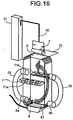
- the circulation-air generating unit 6 includes an inlet portion 62 having an inlet opening 61 with a large diameter, and an outlet portion 64 having a compressed-air supply opening 63 arranged on a periphery of an outlet side of the inlet portion 62.
- the circulation-air generating unit 6 inlets air from the inlet portion 62 by high-velocity airflow supplied from the compressed-air supply opening 63 generated toward an outlet opening 65 of the outlet portion 64, and outlets air with amount of several times to dozens of times of amount of compressed air supplied from the compressed-air supply opening 63.
- the circulation-air generating unit 6 is arranged on a side surface constituting the circulation path near the bottom portion of the cleaning tank 5, with the inlet opening 61 side up while the outlet opening 65 side down.
- the cleaning-medium accelerating unit 7 includes a plurality of acceleration nozzles 71a arrayed on a front surface orthogonal to an internal surface constituting the circulation path, and a plurality of acceleration nozzles 71b arrayed on a back surface facing the front surface with the acceleration nozzles 71a arranged.
- the cleaning-medium accelerating unit 7 blowouts compressed air supplied from a compressed-air source, such as a compressor and a compression tank, inside the cleaning tank 5 via each of the acceleration nozzles 71a and 71b to cause the cleaning medium 4 to collide with the cleaning target object 2. It is preferable to use a blowout nozzle, like the circulation-air generating unit 6, for the acceleration nozzles 71a and 71b.
- the cleaning-medium accelerating unit 7 arranged on a surface orthogonal to the surface constituting the circulation path of the circulation air inside the cleaning tank, and with the nozzle of the cleaning-medium accelerating unit 7 embedded inside the surface of the cleaning tank, it is possible to avoid interference in circulation of the circulation air and effectively cause the cleaning medium to collide with the cleaning target object.
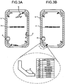
- the cleaning-medium recycle unit 8 includes a separation member 81 and a hood 82 arranged on an internal surface of the bottom portion of the cleaning tank 5, forming a closed space as shown in a perspective view of Fig. 5A and a partial cross section of Fig. 5B .
- the closed space is connected to a dust collector (not shown) including a negative-pressure generating source via a suction tube 11, such as a hose, to generate negative pressure in the hood 82.
- the separation member 81 includes a plurality of small poles and slits 83 in a size through which air and particles can pass while the cleaning medium 4 cannot pass, and are made of porous member, such as metal, plastic mesh, mesh, punched metal plate, and slit plate. With this configuration, the separation member 81 removes dust removed from the cleaning target object 2, and eliminates the cleaning medium 4 worn and chipped by collision with the cleaning target object 2, or the cleaning medium 4 with degraded elasticity due to long-term use.
- the cleaning-medium recycle unit By arranging the cleaning-medium recycle unit at the bottom portion of the cleaning tank, it is possible to increase possibility that the cleaning medium, which has been fallen down the bottom portion of the cleaning tank by gravitation, passes through the cleaning-medium recycle unit, increasing efficiency of recycling the cleaning medium. As a result, the cleanness of the cleaning medium can be improved, improving quality in cleaning.
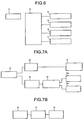
- a controller 12 of the dry cleaning device 1 includes an air-circulation solenoid valve 14, an acceleration solenoid valve 15, an acceleration-switching control valve 16, and a recycling solenoid valve 17, which are connected to the controller 12 with one another, and controls each of the solenoid valves by a drive signal from a driving unit 13, as shown in a block diagram of Fig. 6 and pipeline diagrams shown in Figs. 7A and 7B .
- the air-circulation solenoid valve 14 performs conduction and non-conduction of an air pipe for supplying compressed air from a compressed-air supplying device 18 to the circulation-air generating unit 6.
- the acceleration solenoid valve 15 performs conduction and non-conduction of an air pipe for supplying compressed air to the cleaning-medium accelerating unit 7.
- the acceleration-switching control valve 16 switches directions of flow of compressed air to be supplied to the acceleration nozzles 71a and 71b respectively arranged on side surfaces of the cleaning-medium accelerating unit 7.
- the recycling solenoid valve 17 performs conduction and non-conduction of the suction tube 11 connecting the cleaning-medium recycle unit 8 to a dust collector 19.
- the flaked-shaped cleaning medium 4 is introduced into the cleaning tank 5 and accumulated on the separation member 81 of the cleaning-medium recycle unit 8. Subsequently, the cleaning target object 2 held by the work holding unit 20 is loaded from the cleaning-target loading port 9 by the work moving unit 21 and set at an initial position. The cover 10 is closed to seal off the cleaning tank 5.
- the controller 12 Upon receiving a cleaning start signal by an operation of the driving unit 13, the controller 12 opens the air-circulation solenoid valve 14 and supplies compressed air to the circulation-air generating unit 6 from the compressed-air supplying device 18, such as a compressor, so that the circulation-air generating unit 6 generates circulation air that flows along the circulation path arranged on the internal surfaces of the cleaning tank 5.
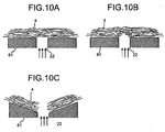
- the circulation air flows along the separation member 81, so that the circulation air acts on the flaked-shaped cleaning medium 4 accumulated on the separation member 81 from a longitudinal direction as shown in Fig. 9A , and gradually chips away accumulation of the cleaning medium 4 from an upper portion of the accumulation.
- the cleaning medium 4 is delivered and flown up in the cleaning tank 5 as shown in Figs. 9B and 9C . Because the circulation air for flowing up the cleaning medium 4 is directly blown from the circulation-air generating unit 6 into the cleaning tank 5, large impact force can be applied to the accumulated cleaning medium 4. Therefore, it is possible to assuredly flow up the accumulated cleaning medium 4 by the circulation air.
- the circulation-air generating unit generates the circulation air that flows along the surface of the cleaning medium accumulated on the cleaning-medium recycle unit. Therefore, it is possible to apply large force for flowing up the accumulated cleaning medium to a large amount of the cleaning media, and circulate the cleaning medium along the internal surfaces of the cleaning tank. As a result, cleaning efficiency can be improved.
- the circulation air is not dispersed and its force is not lost upon flowing. Therefore, it is possible to effectively apply the force of the circulation air to the cleaning medium accumulated on the bottom portion of the cleaning tank. Furthermore, it is possible to deliver and flow up the cleaning medium even with small number of the circulation-air generating units and small amount of air supplied to the circulation-air generating unit. As a result, it is possible to suppress amount of energy necessary for cleaning.
- the cleaning medium 4 is delivered by air using a duct or a hose, the cleaning medium 4 may be clogged in the duct or the hose.
- the circulation path of the circulation air is formed on the internal surfaces of the cleaning tank 5 in the first embodiment, it is possible to avoid clogging the cleaning medium 4 in the circulation path, resulting in flowing up the cleaning medium 4 in the cleaning tank 5.
- circulation air for delivering and flowing up the flaked-shaped flexible cleaning medium flows along the internal surfaces of the cleaning tank, so that the circulation air is not dispersed and its force is not lost. Therefore, it is possible to effectively apply force of the circulation air to the cleaning medium accumulated on the cleaning tank, delivering and flowing up a large amount of the cleaning media with less amount of air supplied. As a result, energy consumption necessary for cleaning can be suppressed. Furthermore, even when once-removed dust is re-attached to the internal surfaces of the cleaning tank, the internal surfaces can be continuously cleaned because a large amount of the cleaning media is circulating. Therefore, it is possible to reduce operations in maintenance, such as cleaning, of the cleaning tank.
- the circulation-air generating unit 6 that generates circulation air is arranged with the inlet opening 61 side up and the outlet opening 65 side down, around the bottom portion of a side surface constituting the circulation path in the cleaning tank 5. Therefore, it is possible to apply air with strong force to the cleaning medium 4 accumulated on the separation member 81 on the bottom portion of the cleaning tank 5, along a bottom surface of the cleaning tank 5. As a result, it is possible to deliver the cleaning medium 4 along the internal surfaces of the cleaning tank 5 to an area away from the outlet opening 65.
- the cleaning media 4 introduced into the inlet opening 61 are dispersed, reducing space density. Therefore, the cleaning medium 4 hardly clogs the inlet opening 61, resulting in stably generating the circulation air.
- the controller 12 closes the air-circulation solenoid valve 14 when a predetermined time elapsed, and causes the circulation-air generating unit 6 to stop generating the circulation air. Subsequently, the controller 12 causes the work moving unit 21 to move down the cleaning target object 2 from the initial position, opens the acceleration solenoid valve 15 to supply compressed air to the cleaning-medium accelerating unit 7 via the acceleration-switching control valve 16, so that compressed air is blown out from the acceleration nozzle 71a of the cleaning-medium accelerating unit 7. The controller 12 opens the recycling solenoid valve 17 to conduct the cleaning-medium recycle unit 8 to the dust collector 19, and generates negative pressure in the hood 82.
- the cleaning medium 4 flown by the circulation air is fallen down.
- the falling down cleaning medium 4 is caused to collide with the cleaning target object 2 by the compressed air blown from the acceleration nozzle 71a, removing the dust 3 attached to a surface of the cleaning target object 2.
- the dust 3 removed from the cleaning target object 2 and the cleaning medium 4 with the dust attached due to collision with the cleaning target object 2 are fallen by gravity, and accumulated on the separation member 81 of the cleaning-medium recycle unit 8 that is vacuuming air due to the negative pressure inside the hood 82.
- the dust fallen on the separation member 81 and the dust attached to the cleaning medium 4 are vacuumed into the hood 82 due to the negative pressure inside the hood 82, and collected by the dust collector 19. As a result, the cleaning medium 4 with the dust attached can be effectively recycled.
- the controller 12 Upon blowing compressed air from the acceleration nozzle 71a for a predetermined time period, the controller 12 closes the acceleration solenoid valve 15 and the recycling solenoid valve 17, and stops operations of the cleaning-medium accelerating unit 7 and the cleaning-medium recycle unit 8.
- the recycling solenoid valve 17 When the recycling solenoid valve 17 is closed, the negative pressure inside the hood 82 is released, so that vacuum force of the hood 82 to the cleaning medium 4 accumulated on the separation member 81 is lost. Therefore, the cleaning medium 4 is removed from the separation member 81 by subsequent flow of the circulation air. Accordingly, the dust can be continuously removed from the cleaning medium 4 without causing the cleaning medium 4 to cover and seal a mesh portion of the separation member 81. Therefore, it is not required to replace all the cleaning media 4, making it possible to effectively use the cleaning medium 4 by supplying deficient amounts due to damage. As a result, maintenance efficiency can be improved.
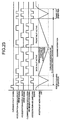
- the controller 12 re-opens the air-circulation solenoid valve 14 to cause the circulation-air generating unit 6 to generate circulation air, flows the cleaning medium 4 recycled and accumulated on the separation member 81 of the cleaning-medium recycle unit 8 for a predetermined time period T1. Subsequently, the controller 12 opens the acceleration solenoid valve 15 and the recycling solenoid valve 17 to switch the acceleration-switching control valve 16 to the acceleration nozzle 71b, and performs a process of removing dust from the cleaning target object 2 and a process of recycling the cleaning medium 4 for a predetermined time period.
- the time for performing the processes of removing dust from the cleaning target object 2 and recycling the cleaning medium 4 are set longer than a time for generating the circulation air, so that wide range of the cleaning target object 2 can be cleaned. Because compressed air is blown out alternately from each of the acceleration nozzles 71a and 71b, it is possible to avoid interference between air blown out from each of the acceleration nozzles 71a and 71b. Therefore, it is possible to assuredly cause the cleaning medium 4 to collide with the cleaning target object 2. As a result, cleaning efficiency of the cleaning medium 4 can be improved.
- the processes of generating the circulation air, removing dust from the cleaning target object 2, and recycling the cleaning medium 4 are repeatedly performed while the cleaning target object 2 gradually moves down from the initial position.
- the work moving unit 21 stops moving down the cleaning target object 2, and gradually moves up the cleaning target object 2.
- the controller 12 alternately performs each of the processes of generating the circulation air, removing dust from the cleaning target object 2, and recycling the cleaning medium 4 when the cleaning target object 2 is gradually moving up, removing the dust 3 from an entire surface of the cleaning target object 2.
- Fig. 11B when the cleaning target object 2 reaches a turn-round position, the work moving unit 21 stops moving down the cleaning target object 2, and gradually moves up the cleaning target object 2.
- the controller 12 alternately performs each of the processes of generating the circulation air, removing dust from the cleaning target object 2, and recycling the cleaning medium 4 when the cleaning target object 2 is gradually moving up, removing the dust 3 from an entire surface of the cleaning target object 2.
- the controller 12 stops a cleaning operation.
- the controller 12 opens the cover 10 of the cleaning tank 5 to discharge the cleaning target object 2 held by the work holding unit 20 from the cleaning tank 5 using the work moving unit 21. Subsequently, the cleaning target object 2 is replaced with new cleaning target object and the cleaning operation is restarted.
- the compressed air is alternately blown out from each of the acceleration nozzles 71a and 71b of the cleaning-medium accelerating unit 7 to clean an entire surface of the cleaning target object 2, it is possible to simultaneously blow out compressed air from each of the acceleration nozzles 71a and 71b by adjusting an angle for blowing air.
- dust is attached to exclusively on one surface of the cleaning target object 2, it is sufficient to blow compressed air from one of the acceleration nozzles 71a and 71b.
- the cleaning-medium accelerating unit By arranging the cleaning-medium accelerating unit in such a manner that generated air and circulation air generated by the circulation-air generating unit do not flow in the same plane, avoiding interference between the circulation air and the air for accelerating the cleaning medium. As a result, it is possible to realize stable cleaning performance.
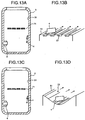
- the circulation path of the circulation air generated by the circulation-air generating unit is formed on a flat surface inside the cleaning tank 5, it is possible to arrange a plurality of grooves 23 formed in a square shape or in a curved surface along a direction of flow of the circulation air, on a surface 51 constituting the circulation path in the cleaning tank 5 as shown in Figs. 13A and 13B . It is preferable to arrange the groove 23 with a width smaller than a face size of the cleaning medium 4, so that the cleaning medium 4 hardly falls into the groove 23.
- a space is formed between the surface 51 of the cleaning tank 5 and the cleaning medium 4, so that contact resistance between the surface 51 and the cleaning medium 4 can be reduced.
- a height of the groove 23 is sufficient as long as air can pass through the groove 23. For example, if the height is set in a range between 0.1 millimeter (mm) and 1 mm, the groove 23 can be easily processed.
- the surface 51, on which the circulation path is formed in the cleaning tank 5, is formed on a concavely curved surface as shown in Figs. 13C and 13D .
- the surface 51 formed on the concavely curved surface it is possible to prevent dispersion of the circulation air. Accordingly, a large amount of the cleaning media 4 can be delivered, making it possible to disperse large amounts of the cleaning media 4 in the cleaning tank 5. As a result, cleaning efficiency can be improved.
- an air rectifying unit 24 that leads the cleaning medium 4 toward the cleaning-medium accelerating unit 7, on an upper surface or an upper portion of a side surface of the cleaning tank 5, where the circulation path is formed.
- the air rectifying unit 24 By arranging the air rectifying unit 24 on the circulation path, it is possible to disperse a large amount of the cleaning media 4 between the cleaning-medium accelerating unit 7 and the cleaning target object 2, resulting in improving cleaning efficiency.
- the air rectifying unit that leads the circulation air toward a path of blowing high-velocity air from the cleaning-medium accelerating unit, it is possible to assuredly cause the cleaning medium to collide with the cleaning target object even when the air flow speed for delivering the cleaning medium increases. Therefore, it is possible to reduce such a loss that the cleaning medium circulates without colliding with the cleaning target object. As a result, it is possible to effectively use the cleaning medium. Furthermore, it is possible to use kinetic energy delivered through the circulation path in addition to energy from the cleaning-medium accelerating unit to cause the cleaning medium to collide with the cleaning target object. Therefore, cleaning efficiency can be improved.
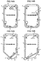
- Figs. 15A and 15B it is possible to arrange an inclined surface 52 including an opening portion on a bottom portion of the cleaning tank 5, without forming the cleaning tank in a rectangular shape. It is possible to arrange the cleaning-medium recycle unit 8 on the inclined surface 52, the circulation-air generating unit 6 on the lower portion of the inclined surface 52, and flows the circulation air along the inclined surface from the circulation-air generating unit 6. With such configuration, when the cleaning medium 4 falls on the separation member 81 of the cleaning-medium recycle unit 8 after removing the dust from the cleaning target object 2 by a collision with the cleaning target object 2, the cleaning medium 4 can be easily collected around the outlet opening 65 of the circulation-air generating unit 6.
- the circulation-air generating unit 6 is singularly arranged in the cleaning tank 5.
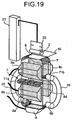
- the circulation-air generating units 6a and 6b are arranged outside of the cleaning tank 5, the outlet opening 65 is arranged at the lower portion of the cleaning tank 5, and the inlet opening 61 is connected to an upper portion of the cleaning tank 5 via a duct hose 25.
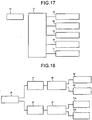
- the controller 12 controls an operation of a circulation-switching control valve 26 that switches supply of compressed air to the circulation-air generating units 6a and 6b as shown in a block diagram of Fig. 18 , in addition to the air-circulation solenoid valve 14, the acceleration solenoid valve 15, the acceleration-switching control valve 16, and the recycling solenoid valve 17 as shown in a block diagram of Fig. 17 .
- the controller 12 controls the circulation-switching control valve 26 to alternately generate the circulation air from each of the circulation-air generating units 6a and 6b. Accordingly, the cleaning media 4 are hardly accumulated inside the cleaning tank 5. Therefore, it is possible to effectively use the cleaning medium 4 inside the cleaning tank 5, increasing possibility of collision between the cleaning medium 4 and the cleaning target object 2. As a result, cleaning efficiency can be improved.
- the inlet opening 61 is connected to the cleaning tank 5 via the duct hose 25, because the duct hose 25 is connected to the upper portion of the cleaning tank 5, where space density due to the cleaning medium 4 is small, it is possible to prevent the cleaning medium 4 from clogging the duct hose 25 or the circulation-air generating units 6a and 6b.
- the cleaning-medium recycle unit 8 is singularly arranged in the cleaning tank 5, it is possible to arrange a plurality of the cleaning-medium recycle units 8 in a third embodiment of the present invention.
- a plurality of cleaning-medium recycle units 8a to 8d which sandwich the arrayed acceleration nozzles 71a and 71b, in addition to the cleaning-medium recycle unit 8 arranged on the bottom portion of the cleaning tank 5.
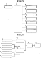
- the controller 12 controls operations of each of a suction-switching control valve 27 that switches a suction operation performed to the cleaning-medium recycle unit 8, and a suction-switching control valve 28 that switches a suction operation performed to each of the cleaning-medium recycle units 8a to 8d as shown in a block diagram of Fig. 21 , in addition to the air-circulation solenoid valve 14, the acceleration solenoid valve 15, the acceleration-switching control valve 16, the recycling solenoid valve 17, and the circulation-switching control valve 26 as shown in a block diagram of Fig. 20 . As shown in Fig.
- the controller 12 when cleaning the cleaning target object 2 by blowing compressed air from the acceleration nozzle 71a arranged on a front surface of the cleaning tank 5, the controller 12 connects the suction-switching control valve 28 to the cleaning-medium recycle unit 8, and connects the suction-switching control valve 28 to the cleaning-medium recycle units 8c and 8d arranged on a back surface of the cleaning tank 5.
- the controller 12 when cleaning the cleaning target object 2 by blowing compressed air from the acceleration nozzle 71b arranged on the back surface of the cleaning tank 5, the controller 12 connects the suction-switching control valve 28 to the cleaning-medium recycle units 8a and 8b arranged on the front surface of the cleaning tank 5.
- the dust 3 and the cleaning medium 4 flown up by the compressed air blown from the acceleration nozzle 71a are stuck to the cleaning-medium recycle units 8c and 8d.
- air-flow from the acceleration nozzle 71a acts on the dust 3 and the cleaning medium 4, in addition to suction air from the cleaning-medium recycle units 8c and 8d. Therefore, it is possible to largely increase flow speed at a mesh portion of the separation member 81 of each of the cleaning-medium recycle units 8c and 8d, improving performance of removing the dust 3 attached to the cleaning medium 4. As a result, the cleaning medium 4 can be assuredly recycled.
- the cleaning-medium recycle units 8c and 8d terminates a suction operation after a predetermined time elapsed. Therefore, it is possible to assuredly remove, from the cleaning-medium recycle units 8c and 8b, the cleaning medium stuck to the cleaning-medium recycle units 8c and 8b.
- the flaked-shaped cleaning medium 4 is introduced into the cleaning tank 5 and accumulated on the separation member 81 of the cleaning-medium recycle unit 8. Subsequently, the cleaning target object 2 held by the work holding unit 20 is loaded from the cleaning-target loading port 9 by the work moving unit 21, and set at an initial position. The cover 10 is closed to seal off the cleaning tank 5.
- the controller 12 Upon receiving a cleaning start signal by an operation of the driving unit 13, the controller 12 opens the acceleration solenoid valve 15 to switch the acceleration-switching control valve 16 at a predetermined interval, so that each of the acceleration nozzles 71a and 71b alternately blows compressed air.
- the controller 12 switches the acceleration-switching control valve 16 in synchronization with switching of blowing compressed air from each of the acceleration nozzles 71a and 71b, to switch adsorption performed by each pair of the cleaning-medium recycle units 8a, 8b, and 8c, 8d, arranged on surfaces facing each of the acceleration nozzles 71a and 71b.
- the cleaning-medium recycle units 8c and 8d arranged on the back surface of the cleaning tank 5 performs suction operation.
- the circulation-air generating unit 6 generates circulation air to deliver and flow up the cleaning medium 4 accumulated on the separation member 81 of the cleaning-medium recycle unit 8, and the cleaning target object 2 is cleaned using the flowing cleaning medium 4.
- each of the acceleration nozzles 71a and 71b alternately blows compressed air, so that the controller 12 switches the acceleration-switching control valve 16 in synchronization with switching of blowing compressed air from each of the acceleration nozzles 71a and 71b. Accordingly, suction performed by each pair of the cleaning-medium recycle units 8a, 8b, and 8c, 8d, which are arranged on surfaces respectively facing the acceleration nozzles 71a and 71b, can be switched from one another. Subsequently, the controller 12 shakes off the cleaning medium 4 attached by static electricity to the cleaning target object 2, and terminates a cleaning operation.
- the controller 12 opens the cover 10 of the cleaning tank 5 to take off the cleaning target object 2 from the cleaning tank 5 by the work moving unit 21, and replaces the cleaning target object with a new cleaning target object to restart the cleaning operation.
- the cleaning-medium recycle units 8a to 8d are arranged on the front and the back surfaces of the cleaning tank 5, it is possible to arrange differently.
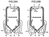
- inclined surfaces 52a and 52b including respective openings, which make V-shaped bottom portion of the cleaning tank 5, are arranged on a bottom portion of the cleaning tank 5,
- the cleaning-medium recycle units & is arranged on each of the inclined surfaces 52a and 52b
- the circulation-air generating units 6a and 6b are arranged at respective lower end portions of the inclined surfaces 52a and 52b
- the air rectifying unit 24 that leads the cleaning medium 4 toward the cleaning-medium accelerating unit 7, on a top surface or a top portion of a side surface of the cleaning tank 5 constituting the circulation path of the circulation air.
- the circulation-air generating unit that generates circulation air along each of the inclined surfaces is arranged on the lower end portion of each of the inclined surfaces, and each of the circulation-air generating unit arranged on each of the lower end portions of the inclined surfaces are alternately operated, the cleaning medium can be collected at one area on the circulation path. Furthermore, the circulation air is intermittently generated along the internal surfaces of the cleaning tank to circulate the collected cleaning medium along the internal surfaces of the cleaning tank. Thus, it is possible to deliver a large amount of the cleaning media at one time with less amounts of air. As a result, energy saving can be realized and cleaning efficiency can be improved.
- the cleaning media 4 are flown up to clean the cleaning target object 2 by colliding with the cleaning target object 2, part of the cleaning media 4 are discharged to the dust collector 19 through the mesh portion included in the separation member 81 of the cleaning-medium recycle unit 8. Accordingly, the number of the cleaning media 4 in the cleaning tank 5 decreases during cleaning. When amount of the flowing cleaning medium 4 decreases in the cleaning tank 5 due to a decrease of the number of the cleaning media 4 in the cleaning tank 5, cleaning effect decreases. In some cases, a plurality of the cleaning target objects 2 held by the work holding unit 20 are loaded into the cleaning tank 5 for cleaning.
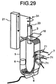
- the medium-amount measuring unit 29 is constituted of a photoelectronic sensor 291 arranged in such a manner that an optical axis of the photoelectronic sensor 291 becomes orthogonal to a direction of circulation of the cleaning medium 4 as shown in Fig. 26 .
- the cleaning-target detecting units 30a and 30b are constituted of a photoelectronic sensor including a light projecting/receiving unit 301 and a reflecting plate 302.
- the light projecting/receiving unit 301 is attached to either the front surface or the back surface of the cleaning tank 5 via a transparent window for preventing interference with the cleaning medium 4.
- the reflecting plate 302 is attached to an internal surface that faces the light projecting/receiving unit 301, and arranged in such a manner that its optical axis crosses the cleaning tank 5 in a longitudinal direction.
- the medium-amount measuring unit 29, and the cleaning-target detecting units 30a, 30b are connected to the controller 12 as shown in Fig. 27 .
- the controller 12 measures how many times the optical axis of the photoelectronic sensor 291 as the medium-amount measuring unit 29 is blocked, quantifies amounts of the flowing cleaning medium 4 during a predetermined time period, and controls the cleaning operation when one of the cleaning-target detecting units 30a and 30b detects the cleaning target object 2.
- the circulation-air generating unit 6 After a plurality of the cleaning target objects 2 held by the work holding unit 20 are loaded into the cleaning tank 5 as shown in Fig. 25 , and when receiving a cleaning start signal, the circulation-air generating unit 6 generates circulation air for delivering the cleaning medium 4 accumulated on the cleaning-medium recycle unit 8 and flowing up the cleaning medium 4 inside the cleaning tank 5.
- the photoelectronic sensor 291 as the medium-amount measuring unit 29 detects the amount of the flowing cleaning medium 4 and inputs measured amount to the controller 12.
- the controller 12 compares input amount of the flowing cleaning medium 4 in a predetermined time period with a predetermined threshold. When the amount of the flowing cleaning medium 4 exceeds the threshold, the controller 12 starts a cleaning operation.
- the controller 12 When the amount of the flowing cleaning medium 4 is equal to or smaller the threshold, the controller 12 issues a warning indicating scarcity of the cleaning medium 4, and terminates the cleaning operation. Subsequently, when the cleaning medium 4 with a predetermined amount or an amount corresponding to the scarcity is supplied from a hopper or the like. When the cleaning medium 4 is flown up in response to the reception of the cleaning start signal, and the amount of the flowing cleaning medium 4 exceeds the threshold, the controller 12 restarts the cleaning operation.
- the controller 12 determines cleaning quality from the amount of the flowing cleaning medium 4 for each predetermined time period. Furthermore, it is possible to assuredly quantify the cleaning quality and cleaning performance by recording variation of the amount of the flowing cleaning medium 4.
- a plurality of the cleaning target objects 2 held by the work holding unit 20 is moved up and down by the work moving unit 21.
- the controller 12 determines a timing of performing an operation of blowing compressed air from the acceleration nozzle 71a and a suction operation by the cleaning-medium recycle unit 8.
- the timing is determined to include a delayed time taken by the cleaning target object 2 to reach a position of the acceleration nozzles 71a and 71b based on a moving speed of the cleaning target object 2 and a distance between the cleaning-target detecting unit 30a and the acceleration nozzles 71a and 71b. Subsequently, the controller 12 stops flowing circulation air at the timing, blows compressed air from the acceleration nozzle 71a, and cleans the first cleaning target object 2 by causing the cleaning-medium recycle unit 8 to start the suction operation.
- the controller 12 terminates the operation of blowing the compressed air from the acceleration nozzle 71a and the suction operation of the cleaning-medium recycle unit 8, at a timing including a delayed time taken by the cleaning target object 2 to reach a position of the acceleration nozzles 71a and 71b, which is obtained from a moving speed of the cleaning target object 2 and a distance between the cleaning-target detecting unit 30a and the acceleration nozzles 71a and 71b. Subsequently, the controller 12 causes the circulation-air generating unit 6 to generate circulation air.
- the controller 12 repeats the above control operation every time the cleaning-target detection signal is input from the cleaning-target detecting unit 30a, and sequentially cleans each of the cleaning target objects 2.
- the controller 12 repeats the above control operation every time the cleaning-target detection signal is input from the cleaning-target detecting unit 30b arranged under the acceleration nozzles 71a and 71b to blow compressed air from the acceleration nozzle 71b. Accordingly, the entire surfaces of the cleaning target objects 2 can be cleaned.
- the photoelectronic sensor 291 is used as the medium-amount measuring unit 29, it is possible to employ a method of accumulating impact force of the cleaning medium 4 to the cleaning target ⁇ object 2 by a force sensor, weight measurement at a time of termination of a process by a weight sensor, or a method of measuring accumulation amount at a bottom portion of the cleaning tank 5 by a distance sensor or the like.
- a force sensor weight measurement at a time of termination of a process by a weight sensor
- a method of measuring accumulation amount at a bottom portion of the cleaning tank 5 by a distance sensor or the like.
- a work-position changing unit 31 that rotates the work holding unit 20 in a direction of rotation of an axis in a longitudinal direction by a motor or an air cylinder, between the work moving unit 21 and the work holding unit 20.
- the cleaning target object 2 held by the work holding unit 20 and loaded into the cleaning tank 5 is rotated by the work-position changing unit 31 to move up and down in the cleaning tank 5, and cleaned by alternately blowing compressed air from a plurality of pairs of the acceleration nozzles 71.
- the cleaning target object 2 is rotated when moving up and down, and compressed air is blown to the cleaning target object 2 from each different direction. Therefore, it is possible to assuredly clean an entire surface of the cleaning target object 2 even when the cleaning target object 2 is in a complicated shape.
- the circulation-air generating unit directly generates circulation air that flows along an internal surface of the cleaning tank, generated circulation air is applied to the cleaning medium from a direction orthogonal to a direction of a face of the cleaning medium accumulated in the cleaning tank, so that the cleaning medium is delivered and flown up. Accordingly, it is possible to apply effective force for flowing the accumulated cleaning medium by the circulation air, resulting in flowing large number of the cleaning media and increasing frequency of collision of the cleaning medium with the cleaning target object. As a result, it is possible to realize desired quality in cleaning.
- the cleaning-medium recycle unit removes attachment on the cleaning medium by suction. Therefore, cleanness of the cleaning medium can be maintained, maintaining desired quality in cleaning. Furthermore, the cleaning medium can be repeatedly used, realizing to perform a cleaning with low environmental burdens.
Landscapes
- Engineering & Computer Science (AREA)
- Mechanical Engineering (AREA)
- Physics & Mathematics (AREA)
- General Physics & Mathematics (AREA)
- Cleaning In General (AREA)
Claims (20)
- Trockenreinigungsvorrichtung umfassend:einen Reinigungsbehälter (5) mit einem im Reinigungsbehälter (5) enthaltenen Reinigungsmittel (4);eine Umlufterzeugungseinheit (6) zum Erzeugen von Hochgeschwindigkeitsumluft im Innern des Reinigungsbehälters (5), sodass im Reinigungsbehälter (5) vorhandenes Reinigungsmittel (4) nach oben fließt,eine Reinigungsmittelbeschleunigungseinheit (7) zum Beschleunigen des Reinigungsmittels (4), das in den Reinigungsbehälter (5) geflossen ist, sodass das Reinigungsmittel (4) mit einem zu reinigenden Zielobjekt zusammenstößt, sodass die am zu reinigenden Zielobjekt haftenden Partikeln getrennt werden; undeine Reinigungsmittel-Recyclingeinheit (8) zum Aufsaugen der vom Reinigungszielobjekt getrennten Partikel und zum Recyceln des Reinigungsmittels (4);dadurch gekennzeichnet dass das Reinigungsmittel ein flexibles flockenförmiges Reinigungsmittel (4) ist, das eine Oberfläche im Bereich zwischen 1 mm2 und 1000 mm2 und eine Dicke im Bereich zwischen 1 µm und 500 µm aufweist.
- Trockenreinigungsvorrichtung nach Anspruch 1, wobei die Umlufterzeugungseinheit (6) dafür eingerichtet ist, eine Umluft zu erzeugen, die entlang einer inneren Fläche des Reinigungsbehälters (4) fließt.
- Trockenreinigungsvorrichtung nach Anspruch 1 oder 2, wobei die Umlufterzeugungseinheit (6) zum Erzeugen von Umluft vorgesehen ist, die entlang der Reinigungsmittel-Recyclingeinheit (8) fließt.
- Trockenreinigungsvorrichtung nach Anspruch 1 oder 2, wobei die Umlufterzeugungseinheit (6) zum Erzeugen von Umluft vorgesehen ist, die entlang einer Längsrichtung des Reinigungsbehälters (5) fließt.
- Trockenreinigungsvorrichtung nach Anspruch 1 oder 2, wobei die Umlufterzeugungseinheit (6) folgendes umfasst:ein zylindrisches Eingangsglied (62) mit einer ersten Eingangsöffnung (61) und einer ersten Ausgangsöffnung, wobei die erste Eingangsöffnung (61) größer ist als die erste Ausgangsöffnung, und die erste Ausgangsöffnung größer ist als das Reinigungsmittel (4); undein zylindrisches Ausgangsglied (64) mit einer zweiten Eingangsöffnung, einer Lufteingangsöffnung (63), und einer zweiten Ausgangsöffnung (65), wobei die zweite Eingangsöffnung größer ist als die erste Ausgangsöffnung und um die erste Ausgangsöffnung angeordnet ist, und die Lufteingangsöffnung (63) nahe der zweiten Eingangsöffnung angeordnet ist, wobeidie Umlufterzeugungseinheit so eingerichtet ist, dass Hochgeschwindigkeitsluft von der Lufteingangsöffnung (63) in das zylindrische Ausgangsglied (64) fließt, sodass das Reinigungsmittel (4) von der ersten Eingangsöffnung (61) in das zylindrische Eingangsglied (62) eintritt, dann im zylindrischen Ausgangsglied (64) von der ersten Ausgangsöffnung und der zweiten Eingangsöffnung eintritt, und zuletzt das zylindrische Ausgangsglied (64) aus der zweiten Ausgangsöffnung (65) verlässt.
- Trockenreinigungsvorrichtung nach Anspruch 5, wobei die erste Eingangsöffnung (61) an einer höheren Stelle angeordnet ist, als die der Ausgangsöffnung im Reinigungsbehälter (5).
- Trockenreinigungsvorrichtung nach Anspruch 1 oder 2, wobei die Umlufterzeugungseinheit (6) mehrfach vorgesehen ist, und
die Trockenreinigungsvorrichtung ferner einen Controller (12) zum Umschalten des Erzeugens der Umluft für jede der Umlufterzeugungseinheiten (6) umfasst. - Trockenreinigungsvorrichtung nach Anspruch 1 oder 2, ferner umfassend einen Controller (12) zum intermittierenden Antrieb von mindestens zwei von der Umlufterzeugungseinheit (6), der Reinigungsmittelbeschleunigungseinheit (7) und der Reinigungsmittel-Recyclingeinheit (8).
- Trockenreinigungsvorrichtung nach Anspruch 1 oder 2, wobei die Reinigungsmittelbeschleunigungseinheit (7) auf einer Fläche des Reinigungsbehälters (5) angeordnet ist, wobei die Fläche senkrecht zu einer anderen Fläche steht, auf der ein Umluftpfad angeordnet ist, wobei die Umluft entlang dem Umluftpfad fließt.
- Trockenreinigungsvorrichtung nach Anspruch 1 oder 2, wobei die Reinigungsmittelbeschleunigungseinheit (7) eine in einer Fläche des Reinigungsbehälters (5) eingebettete Düse umfasst.
- Trockenreinigungsvorrichtung nach Anspruch 1 oder 2, wobei die Reinigungsmittel-Recyclingeinheit (8) auf einem unteren Teil des Reinigungsbehälters (5) angeordnet ist.
- Trockenreinigungsvorrichtung nach Anspruch 1 oder 2, wobei die Reinigungsmittel-Recyclingeinheit (8) mehrfach vorgesehen ist, und die Reinigungsmittelrecyclingeinheiten (8) auf einem unteren Teil des Reinigungsbehälters (5) an Stellen, die der Reinigungsmittelbeschleunigungseinheit (7) gegenüberstehen, angeordnet sind.
- Trockenreinigungsvorrichtung nach Anspruch 12, ferner umfassend einen Controller (12) zum abwechselnden Umschalten des Recyclingbetriebs des Reinigungsmittels (4), das von den jeweiligen Reinigungsmittel-Recyclingeinheiten (8) durchgeführt wird.
- Trockenreinigungsvorrichtung nach Anspruch 1 oder 2, wobei eine Mehrzahl von Nuten (23) auf einer Fläche des Reinigungsbehälters (5) entlang einer Strömungsrichtung der Umluft angeordnet ist, wobei die Fläche eine Fläche ist, entlang welcher die Umluft fließt.
- Trockenreinigungsvorrichtung nach Anspruch 1 oder 2, wobei eine gekrümmte konkave Fläche auf einer Fläche des Reinigungsbehälters (5) entlang einer Strömungsrichtung der Umluft angeordnet ist, wobei die Fläche eine Fläche ist, entlang der die Umluft fließt.
- Trockenreinigungsvorrichtung nach Anspruch 1 oder 2, ferner umfassend eine geneigte Fläche (52), die auf einem unteren Teil des Reinigungsbehälters (5) angeordnet ist, wobei
die Reinigungsmittel-Recyclingeinheit (8) auf der geneigten Fläche (52) angeordnet ist, und
die Umlufterzeugungseinheit (6) dafür vorgesehen ist, Umluft zu erzeugen, die entlang der geneigten Fläche (52) strömt, und auf einem unteren Endteil der geneigten Fläche (52) angeordnet ist. - Trockenreinigungsvorrichtung nach Anspruch 1 oder 2, ferner umfassend eine V-förmige geneigte Fläche (52a), die im Innern des Reinigungsbehälters (5) auf einem unteren Teil des Reinigungsbehälters (5) angeordnet ist, wobei
die Reinigungsmittel-Recyclingeinheit (8) auf jeder der Seitenflächen der V-förmigen geneigten Fläche (52a) angeordnet ist, und
die Umlufterzeugungseinheit (6) dafür eingerichtet ist, die Umluft zu erzeugen, die entlang jeder der Seitenflächen der V-förmigen geneigten Fläche (52a) fließt, und auf einem unteren Endteil jeder der Seitenflächen der V-förmigen geneigten Fläche (52a) angeordnet ist. - Trockenreinigungsvorrichtung nach Anspruch 1 oder 2, ferner umfassend eine im Reinigungsbehälter (5) angeordnete Luftrektifizierungseinheit (24), wobei die Luftrektifizierungseinheit (24) zum Leiten der Umluft in Richtung eines Weges, wo Hochgeschwindigkeitsluft von der Reinigungsmittelbeschleunigungseinheit (7) geblasen wird.
- Trockenreinigungsvorrichtung nach Anspruch 1 oder 2, ferner umfassend:eine Mengenmesseinheit (29) zum Ermitteln der Menge des Reinigungsmittels, das im Reinigungsbehälter (5) fließt; undeinen Controller (12) zum Vergleichen des von der Mengenmesseinheit (29) gemessenen Durchsatzes mit einer vorbestimmten Schwelle, und zum Ausgeben einer Warnung wenn der Durchsatz gleich oder niedriger als die Schwelle ist.
- Trockenreinigungsvorrichtung nach Anspruch 1 oder 2, ferner umfassend:eine Reinigungsziel-Ermittlungseinheit (30a) zum Ermitteln des zu reinigenden Zielobjekts im Reinigungsbehälter (5), und Ausgeben eines Signals, das die Feststellung des zu reinigenden Zielobjekts anzeigt; undeinen Controller (12) zum Betreiben der Umlufterzeugungseinheit (6), der Reinigungsmittelbeschleunigungseinheit (7) und der Reinigungsmittel-Recyclingeinheit (8), im Gleichlauf mit dem Signal.
Applications Claiming Priority (3)
| Application Number | Priority Date | Filing Date | Title |
|---|---|---|---|
| JP2006240971A JP4741998B2 (ja) | 2006-09-06 | 2006-09-06 | 洗浄装置及び洗浄方法 |
| JP2006240948A JP4772624B2 (ja) | 2006-09-06 | 2006-09-06 | 洗浄装置 |
| JP2006240920A JP4749287B2 (ja) | 2006-09-06 | 2006-09-06 | 洗浄装置 |
Publications (3)
| Publication Number | Publication Date |
|---|---|
| EP1897628A2 EP1897628A2 (de) | 2008-03-12 |
| EP1897628A3 EP1897628A3 (de) | 2012-03-14 |
| EP1897628B1 true EP1897628B1 (de) | 2016-02-24 |
Family
ID=38792518
Family Applications (1)
| Application Number | Title | Priority Date | Filing Date |
|---|---|---|---|
| EP07253501.6A Expired - Fee Related EP1897628B1 (de) | 2006-09-06 | 2007-09-04 | Trockenreinigungsvorrichtung |
Country Status (4)
| Country | Link |
|---|---|
| US (1) | US7730896B2 (de) |
| EP (1) | EP1897628B1 (de) |
| KR (1) | KR100890983B1 (de) |
| CN (1) | CN101254502B (de) |
Families Citing this family (18)
| Publication number | Priority date | Publication date | Assignee | Title |
|---|---|---|---|---|
| US20040259750A1 (en) * | 2002-04-22 | 2004-12-23 | The Procter & Gamble Company | Processes and apparatuses for applying a benefit composition to one or more fabric articles during a fabric enhancement operation |
| JP4531841B2 (ja) * | 2008-02-27 | 2010-08-25 | 株式会社リコー | 洗浄装置及び洗浄方法 |
| JP5403407B2 (ja) | 2008-06-18 | 2014-01-29 | 株式会社リコー | 洗浄装置 |
| JP4758497B2 (ja) * | 2008-07-10 | 2011-08-31 | 株式会社リコー | 洗浄装置及び洗浄方法 |
| WO2011039972A1 (ja) * | 2009-10-02 | 2011-04-07 | シャープ株式会社 | 清掃ノズル及びそれを備えた塵埃除去装置 |
| JP5589356B2 (ja) * | 2009-11-11 | 2014-09-17 | 株式会社リコー | 乾式洗浄方法および装置 |
| JP5793980B2 (ja) * | 2010-11-10 | 2015-10-14 | 株式会社リコー | 乾式クリーニング筐体及び乾式クリーニング装置 |
| JP5712826B2 (ja) * | 2010-11-17 | 2015-05-07 | 株式会社リコー | 乾式クリーニング筐体及び乾式クリーニング装置 |
| JP5879903B2 (ja) * | 2011-02-25 | 2016-03-08 | 株式会社リコー | 乾式クリーニング筐体、乾式クリーニング装置及び乾式クリーニングシステム |
| JP5953975B2 (ja) | 2011-10-26 | 2016-07-20 | 株式会社リコー | 洗浄媒体飛散防止部材、洗浄対象物保持体及び乾式洗浄装置 |
| JP5919786B2 (ja) | 2011-12-12 | 2016-05-18 | 株式会社リコー | 乾式クリーニング筐体及び乾式クリーニング装置 |
| JP6492429B2 (ja) | 2013-10-15 | 2019-04-03 | 株式会社リコー | 乾式クリーニング筐体、乾式クリーニング装置及び分離板の装着方法 |
| JP2016067991A (ja) * | 2014-09-29 | 2016-05-09 | 株式会社リコー | 洗浄媒体吸引ユニット及び乾式洗浄装置 |
| EP3212017B1 (de) | 2014-10-29 | 2021-06-16 | Altria Client Services LLC | Ethanolfreie gelformulierungskartusche für e-dampfvorrichtung |
| KR20160065226A (ko) * | 2014-11-07 | 2016-06-09 | 세메스 주식회사 | 기판 처리 장치 및 기판 처리 방법 |
| CN106695576B (zh) * | 2017-03-17 | 2023-08-15 | 河南理工大学 | 前混合式脉冲磨料气体射流冲蚀方法及装置 |
| CN107901277B (zh) * | 2017-12-27 | 2019-09-06 | 台州金福桂再生资源利用有限公司 | 一种弯曲废旧塑料的刮洗设备 |
| CN113814226B (zh) * | 2020-06-19 | 2023-01-24 | 理光高科技(深圳)有限公司 | 干式清洗装置 |
Family Cites Families (18)
| Publication number | Priority date | Publication date | Assignee | Title |
|---|---|---|---|---|
| US2440656A (en) * | 1946-03-18 | 1948-04-27 | Fred W Huntington | Abrasive material for polishing |
| JPS63186653A (ja) | 1987-01-30 | 1988-08-02 | キユーピー株式会社 | 容器詰め流動食 |
| JPH0718646B2 (ja) * | 1989-08-22 | 1995-03-06 | ジャパン・フィールド株式会社 | 被洗浄物の乾燥装置 |
| JPH04256477A (ja) * | 1991-02-07 | 1992-09-11 | Hoya Corp | 洗浄方法および洗浄装置 |
| CN2111375U (zh) * | 1991-04-14 | 1992-07-29 | 邓志忠 | 自动除尘式空气滤清器 |
| JP3288462B2 (ja) | 1993-03-01 | 2002-06-04 | シシド静電気株式会社 | 除電式除塵装置 |
| JP3468995B2 (ja) | 1996-07-30 | 2003-11-25 | 澁谷工業株式会社 | 樹脂製容器の清掃方法および装置 |
| JP2889547B2 (ja) | 1997-01-28 | 1999-05-10 | 日本カル株式会社 | 表面付着物の回収処理装置及び方法 |
| US6034351A (en) * | 1998-06-24 | 2000-03-07 | Sato; Katsuhiro | Cleaning apparatus for welding torch nozzle and method of cleaning the same |
| EP1034733A1 (de) * | 1999-03-05 | 2000-09-13 | S.I.EL S.r.l. | Reinigungsgerät |
| CN2443788Y (zh) * | 2000-09-22 | 2001-08-22 | 浙江大学 | 干冰清洗机 |
| JP4187636B2 (ja) | 2003-12-10 | 2008-11-26 | 株式会社リコー | トナー容器乾式洗浄方法及び洗浄装置 |
| JP2005182168A (ja) | 2003-12-16 | 2005-07-07 | Sharp Corp | コンテンツ処理装置、コンテンツ処理方法、コンテンツ処理プログラム、および記録媒体 |
| JP2005296853A (ja) * | 2004-04-13 | 2005-10-27 | Ricoh Co Ltd | 微粉除去装置 |
| JP4546147B2 (ja) | 2004-05-18 | 2010-09-15 | 株式会社リコー | 乾式洗浄方法および装置 |
| JP4318179B2 (ja) | 2004-12-13 | 2009-08-19 | 国立大学法人 香川大学 | D−プシコースを含有する新規二糖類化合物及びその製造方法 |
| JP4670814B2 (ja) | 2005-01-13 | 2011-04-13 | パナソニック株式会社 | 乾式洗浄装置 |
| JP4580916B2 (ja) * | 2005-11-02 | 2010-11-17 | 株式会社リコー | 洗浄装置と洗浄方法 |
-
2007
- 2007-08-29 US US11/896,019 patent/US7730896B2/en not_active Expired - Fee Related
- 2007-09-04 EP EP07253501.6A patent/EP1897628B1/de not_active Expired - Fee Related
- 2007-09-05 KR KR1020070089964A patent/KR100890983B1/ko not_active IP Right Cessation
- 2007-09-06 CN CN200710164876XA patent/CN101254502B/zh not_active Expired - Fee Related
Also Published As
| Publication number | Publication date |
|---|---|
| US20080052953A1 (en) | 2008-03-06 |
| KR100890983B1 (ko) | 2009-03-27 |
| CN101254502A (zh) | 2008-09-03 |
| EP1897628A3 (de) | 2012-03-14 |
| KR20080022522A (ko) | 2008-03-11 |
| EP1897628A2 (de) | 2008-03-12 |
| CN101254502B (zh) | 2012-10-10 |
| US7730896B2 (en) | 2010-06-08 |
Similar Documents
| Publication | Publication Date | Title |
|---|---|---|
| EP1897628B1 (de) | Trockenreinigungsvorrichtung | |
| KR101025180B1 (ko) | 세정 매체 및 이를 사용하는 건식 세정 장치 | |
| US7865997B2 (en) | Dry type cleaning apparatus and dry type cleaning method | |
| JP4598694B2 (ja) | 洗浄装置及び洗浄方法 | |
| JP4898939B2 (ja) | 乾式洗浄装置 | |
| JP5061053B2 (ja) | 乾式洗浄装置と乾式洗浄方法とこれにより洗浄された洗浄物及び再生装置の製造方法 | |
| JP4741998B2 (ja) | 洗浄装置及び洗浄方法 | |
| JP5101873B2 (ja) | 洗浄媒体 | |
| JP4950329B2 (ja) | 洗浄装置 | |
| JP2010279949A5 (de) | ||
| JP4772624B2 (ja) | 洗浄装置 | |
| JP4933374B2 (ja) | 乾式洗浄装置 | |
| JP2007330947A (ja) | 乾式洗浄装置、および乾式洗浄方法 | |
| JP4954030B2 (ja) | 洗浄媒体及びそれを使用する乾式洗浄装置 | |
| JP5298681B2 (ja) | 乾式洗浄装置 | |
| JP4749287B2 (ja) | 洗浄装置 | |
| JP4902399B2 (ja) | 乾式洗浄装置 | |
| JP5310812B2 (ja) | 洗浄媒体およびこれを用いる乾式洗浄装置 | |
| JP2005296853A (ja) | 微粉除去装置 | |
| JP5218615B2 (ja) | 乾式洗浄装置 | |
| JP2002019391A (ja) | 曲面転写方法 |
Legal Events
| Date | Code | Title | Description |
|---|---|---|---|
| PUAI | Public reference made under article 153(3) epc to a published international application that has entered the european phase |
Free format text: ORIGINAL CODE: 0009012 |
|
| 17P | Request for examination filed |
Effective date: 20070911 |
|
| AK | Designated contracting states |
Kind code of ref document: A2 Designated state(s): AT BE BG CH CY CZ DE DK EE ES FI FR GB GR HU IE IS IT LI LT LU LV MC MT NL PL PT RO SE SI SK TR |
|
| AX | Request for extension of the european patent |
Extension state: AL BA HR MK YU |
|
| PUAL | Search report despatched |
Free format text: ORIGINAL CODE: 0009013 |
|
| AK | Designated contracting states |
Kind code of ref document: A3 Designated state(s): AT BE BG CH CY CZ DE DK EE ES FI FR GB GR HU IE IS IT LI LT LU LV MC MT NL PL PT RO SE SI SK TR |
|
| AX | Request for extension of the european patent |
Extension state: AL BA HR MK RS |
|
| RIC1 | Information provided on ipc code assigned before grant |
Ipc: B24C 9/00 20060101ALI20120206BHEP Ipc: B24C 7/00 20060101ALI20120206BHEP Ipc: B08B 7/02 20060101AFI20120206BHEP |
|
| AKX | Designation fees paid |
Designated state(s): DE FR GB IT NL |
|
| GRAP | Despatch of communication of intention to grant a patent |
Free format text: ORIGINAL CODE: EPIDOSNIGR1 |
|
| RIC1 | Information provided on ipc code assigned before grant |
Ipc: B08B 7/02 20060101AFI20150811BHEP Ipc: B24C 5/00 20060101ALI20150811BHEP Ipc: B24C 7/00 20060101ALI20150811BHEP Ipc: B24C 9/00 20060101ALI20150811BHEP |
|
| INTG | Intention to grant announced |
Effective date: 20150903 |
|
| GRAS | Grant fee paid |
Free format text: ORIGINAL CODE: EPIDOSNIGR3 |
|
| GRAA | (expected) grant |
Free format text: ORIGINAL CODE: 0009210 |
|
| AK | Designated contracting states |
Kind code of ref document: B1 Designated state(s): DE FR GB IT NL |
|
| REG | Reference to a national code |
Ref country code: GB Ref legal event code: FG4D |
|
| REG | Reference to a national code |
Ref country code: DE Ref legal event code: R096 Ref document number: 602007044954 Country of ref document: DE |
|
| REG | Reference to a national code |
Ref country code: NL Ref legal event code: FP |
|
| PG25 | Lapsed in a contracting state [announced via postgrant information from national office to epo] |
Ref country code: IT Free format text: LAPSE BECAUSE OF FAILURE TO SUBMIT A TRANSLATION OF THE DESCRIPTION OR TO PAY THE FEE WITHIN THE PRESCRIBED TIME-LIMIT Effective date: 20160224 |
|
| REG | Reference to a national code |
Ref country code: DE Ref legal event code: R097 Ref document number: 602007044954 Country of ref document: DE |
|
| PLBE | No opposition filed within time limit |
Free format text: ORIGINAL CODE: 0009261 |
|
| STAA | Information on the status of an ep patent application or granted ep patent |
Free format text: STATUS: NO OPPOSITION FILED WITHIN TIME LIMIT |
|
| 26N | No opposition filed |
Effective date: 20161125 |
|
| REG | Reference to a national code |
Ref country code: DE Ref legal event code: R119 Ref document number: 602007044954 Country of ref document: DE |
|
| REG | Reference to a national code |
Ref country code: NL Ref legal event code: MM Effective date: 20161001 |
|
| GBPC | Gb: european patent ceased through non-payment of renewal fee |
Effective date: 20160904 |
|
| PG25 | Lapsed in a contracting state [announced via postgrant information from national office to epo] |
Ref country code: NL Free format text: LAPSE BECAUSE OF NON-PAYMENT OF DUE FEES Effective date: 20161001 |
|
| REG | Reference to a national code |
Ref country code: FR Ref legal event code: ST Effective date: 20170531 |
|
| PG25 | Lapsed in a contracting state [announced via postgrant information from national office to epo] |
Ref country code: DE Free format text: LAPSE BECAUSE OF NON-PAYMENT OF DUE FEES Effective date: 20170401 Ref country code: FR Free format text: LAPSE BECAUSE OF NON-PAYMENT OF DUE FEES Effective date: 20160930 Ref country code: GB Free format text: LAPSE BECAUSE OF NON-PAYMENT OF DUE FEES Effective date: 20160904 |