EP1896745B1 - Stelleinrichtung, insbesondere zur verstellung eines fahrzeugsitzes - Google Patents
Stelleinrichtung, insbesondere zur verstellung eines fahrzeugsitzes Download PDFInfo
- Publication number
- EP1896745B1 EP1896745B1 EP06724750A EP06724750A EP1896745B1 EP 1896745 B1 EP1896745 B1 EP 1896745B1 EP 06724750 A EP06724750 A EP 06724750A EP 06724750 A EP06724750 A EP 06724750A EP 1896745 B1 EP1896745 B1 EP 1896745B1
- Authority
- EP
- European Patent Office
- Prior art keywords
- clamping
- positioning device
- outer ring
- wing
- wings
- Prior art date
- Legal status (The legal status is an assumption and is not a legal conclusion. Google has not performed a legal analysis and makes no representation as to the accuracy of the status listed.)
- Expired - Lifetime
Links
Images


Classifications
-
- B—PERFORMING OPERATIONS; TRANSPORTING
- B60—VEHICLES IN GENERAL
- B60N—SEATS SPECIALLY ADAPTED FOR VEHICLES; VEHICLE PASSENGER ACCOMMODATION NOT OTHERWISE PROVIDED FOR
- B60N2/00—Seats specially adapted for vehicles; Arrangement or mounting of seats in vehicles
- B60N2/02—Seats specially adapted for vehicles; Arrangement or mounting of seats in vehicles the seat or part thereof being movable, e.g. adjustable
- B60N2/22—Seats specially adapted for vehicles; Arrangement or mounting of seats in vehicles the seat or part thereof being movable, e.g. adjustable the back-rest being adjustable
- B60N2/2227—Seats specially adapted for vehicles; Arrangement or mounting of seats in vehicles the seat or part thereof being movable, e.g. adjustable the back-rest being adjustable and provided with braking systems
-
- B—PERFORMING OPERATIONS; TRANSPORTING
- B60—VEHICLES IN GENERAL
- B60N—SEATS SPECIALLY ADAPTED FOR VEHICLES; VEHICLE PASSENGER ACCOMMODATION NOT OTHERWISE PROVIDED FOR
- B60N2/00—Seats specially adapted for vehicles; Arrangement or mounting of seats in vehicles
- B60N2/90—Details or parts not otherwise provided for
- B60N2/919—Positioning and locking mechanisms
- B60N2/933—Positioning and locking mechanisms rotatable
- B60N2/938—Positioning and locking mechanisms rotatable and provided with braking systems
-
- F—MECHANICAL ENGINEERING; LIGHTING; HEATING; WEAPONS; BLASTING
- F16—ENGINEERING ELEMENTS AND UNITS; GENERAL MEASURES FOR PRODUCING AND MAINTAINING EFFECTIVE FUNCTIONING OF MACHINES OR INSTALLATIONS; THERMAL INSULATION IN GENERAL
- F16D—COUPLINGS FOR TRANSMITTING ROTATION; CLUTCHES; BRAKES
- F16D41/00—Freewheels or freewheel clutches
- F16D41/06—Freewheels or freewheel clutches with intermediate wedging coupling members between an inner and an outer surface
- F16D41/08—Freewheels or freewheel clutches with intermediate wedging coupling members between an inner and an outer surface with provision for altering the freewheeling action
- F16D41/10—Freewheels or freewheel clutches with intermediate wedging coupling members between an inner and an outer surface with provision for altering the freewheeling action with self-actuated reversing
- F16D41/105—Freewheels or freewheel clutches with intermediate wedging coupling members between an inner and an outer surface with provision for altering the freewheeling action with self-actuated reversing the intermediate members being of circular cross-section, of only one size and wedging by rolling movement not having an axial component between inner and outer races, one of which is cylindrical
Definitions
- the present invention relates to a plurality of clamping body having, operable in both directions adjusting device, in particular for adjusting a vehicle seat.
- An adjusting device for adjusting a motor vehicle seat is for example from the DE 198 54 931 A1 known.
- a so-called pinch roller switching mechanism interacts with a switchable pinch roller locking mechanism, wherein a pivoting movement that can be carried out by a pivot lever can be transmitted via the pinch roller control gear to an output shaft of the switchable pinch roller locking mechanism.
- the pinch roller control gear and the switchable pinch roller locking mechanism have a common geometric axis.
- For storage of various rotatable components of the actuating device a plurality of radial bearings are provided. Overall, the adjusting device is a proven construction, which however is expensive to manufacture.
- the invention has for its object to provide an operable in two directions of rotation adjusting device, in particular for a seat adjustment in a motor vehicle, indicate, which is characterized by a compact design and rational production options and by a particularly high reliability and durability.
- This object is achieved by a setting device with the features of claim 1.
- This adjusting device has a pivotable, preferably manually operable drive element and a rotatable about the same axis, mounted in a housing, acting as an output element outer ring.
- a plurality of parallel to the axis of the drive and the output element extending shift finger are integrally formed.
- shift fingers interact with two radially arranged within the outer ring and coaxial with this, against each other pivotable, Moerieligen clamping plates together: each between a wing of the first clamping disc and a wing of the second clamping disc a recess is formed, in which engages one of the shift finger, so that at Pivoting the drive element either one of the two clamping plates by means of the shift finger is entrained. On each wing of the clamping discs a clamping surface is formed, wherein between the clamping surfaces and the outer ring clamping rollers are guided.
- the adjusting device further comprises a normal to the axis of the drive and the driven element arranged, non-rotatably mounted on the housing cap which has a number of the shift finger corresponding number of Sp Drrucken which engage in the space radially within the outer ring.
- Each expansion cam forms both a spacer between two clamping rollers arranged on adjacent clamping surfaces and in each case a stop for the wing having these clamping surfaces of the clamping disks acting as drive parts.
- the two clamping disks have a matching number of vanes, alternating in the circumferential direction always a wing of the first clamping disc and a wing of the second clamping disc.
- the wings are dimensioned such that they allow a limited pivoting of a clamping disc relative to the other clamping disc. In this case, all the wings are located substantially in a common, normal to the axis of the actuator arranged plane.
- the return spring which acts between a wing of the first clamping disc and a wing of the second clamping disc, the clamping discs are acted upon by a force in the direction of a defined stop position. In this stop or normal position, each shift finger of the drive element is struck on both clamping disks.
- the return springs are preferably formed in a space-saving manner as coil springs.
- each individual return spring is guided so that scraping noises are avoided on components such as the outer ring.
- the return springs for example by means of a holding projection, generally referred to as holding contour, held on the wings of the clamping plates that they are compressible or expandable without contact with the output element in space radially within this output element.
- the clamping disks are preferably made of metal, in particular as sintered metal parts.
- the clamping rollers guided between the clamping surfaces formed on the surfaces of the vanes of the clamping disks and the cylindrical inner wall of the outer ring are permanently loaded with a force in the direction of their clamping position.
- freewheel springs are provided, each acting between a wing of a clamping disc and arranged on this wing pinch roller.
- the latter In order to hold the cap having the expansion cams against rotation on the housing, the latter preferably has at least one receptacle into which a rotation-preventing cam of the cap engages.
- the cap including all cams, i. the expansion cam and anti-rotation cam, is preferably made in one piece from plastic.
- an adjusting device 1 which forms part of a seat adjustment of a motor vehicle seat.
- the function of the adjusting device 1 basically corresponds to the function of the Klemmrollenschalttechniks after DE 198 54 931 A1 , With the adjusting device 1 after FIG. 1 acts another device, not shown together with freewheeling property whose function the switchable Klemmrollengesperre after the DE 198 54 931 A1 equivalent.
- the adjusting device 1 has a housing 2 made of sheet metal, in which a likewise made of metal outer ring 3 is rotatably mounted as an output element.
- the outer ring 3 is surrounded by sections of a ring wall 4, the parts of an in FIG. 2 completely shown cap 5 are made of plastic.
- the cap 5 is held against rotation on the housing 2, wherein two anti-rotation cam 6 of the cap 5 engage in corresponding receptacles 7 of the chipless shaped housing 2.
- the cap 5 has further functions, which are explained in greater detail below.
- FIG. 3 Shown in detail provided switching disc.
- the switching disc 8 is made as a stamped and bent part as the housing 2 made of sheet metal and has three integrally molded shift finger 9, which also in FIG. 1 are visible and extend parallel to the axis A of the drive element 8 and the output element 3.
- a lever for manual actuation of the actuating device 1 is attached to the operating as a drive element switching disc 8.
- a bolt 10 Centrally located within the adjusting device 1 is a bolt 10 whose axis of symmetry defines the axis of rotation A of the drive element 8 and of the driven element 3.
- To the bolt 10 are coaxial with the outer ring 3 and radially within this two three-leaf clamping disks 11, 12 rotatable.
- the total of six wings 13, 14 of the clamping plates 11, 12 substantially in a common, normal to Axis A arranged level, wherein in the circumferential direction always a wing 13 of the first clamping plate 11 and a wing 14 of the second clamping plate 12 alternate.
- Between adjacent wings 13, 14 a total of three recesses 15 are formed, in which engage the shift finger 9 of the drive element 8.
- the clamping discs 11, 12 are connected between the drive member 8 and the outer ring 3 drive parts that allow the transmission of a rotational movement in selectable direction.
- each wing 13, 14 a clamping surface 16, on which a voltage applied to the inside of the outer ring 3 pinch roller 17 is guided.
- the clamping surfaces 16 are formed such that with a fixed outer ring 3, the wings 13, 14 in the direction of the neutral position shown pivotally, but not from this position are movable out.
- each wing 13, 14 On the arm 19 of each wing 13, 14 is located in the area adjacent to the outer ring 3 area a retaining edge 21 as a retaining contour for the return spring 20, which ensures that the return spring 20 does not come into contact with the outer ring 3 during the entire possible pivotal movement of the clamping disc 11, 12. In this way, noises are avoided by any scraping movements.
- the cap 5 has three expansion cams 22, which, in neutral position adjacent to the shift fingers 9, partially engage in the recesses 15.
- the circumferentially measured width of that portion of a Sp Drossee 22 which engages in the recess 15 corresponds to the width of the shift finger 9.
- the paragraphs 23 form approximately in the radial direction extending boundaries of the recess 15th
- each expansion cam 22 in the radially outer region adjoining the outer ring 3 has a spacer 25 with two abutment surfaces 26 facing away from one another in the peripheral direction, for a respective pinch roller 17.
- the contact surface 26 on the surface of the expansion cam 22 ensures that the voltage applied to the contact surface 26 pinch roller 17 is displaced so far from the clamping position that at a rotation of the outer ring 3, the pinch roller 17 tends to push the expansion cam 22, no power flow between the outer ring 3 and the clamping surface 16 on which the pinch roller 17 is constructed.
- the adjusting device 1 comprises a pivotable, in particular manually operable, drive element 8 and a rotatable about the same axis A, mounted in a housing 2 driven element 3 in the form of an outer ring, wherein a plurality of integrally formed on the drive element 8 shift finger 9 extend parallel to the axis A.
- the plurality of realized by the cap 5 functions is of particular advantage.
- a further advantage is that the switching disc 8 has no punched holes or other openings and thus is particularly stable. Likewise, the injection-molded plastic Cap 5 no openings on. Overall, the adjustment mechanism of the adjusting device 1 is completely encapsulated.
Landscapes
- Engineering & Computer Science (AREA)
- Mechanical Engineering (AREA)
- Aviation & Aerospace Engineering (AREA)
- Transportation (AREA)
- General Engineering & Computer Science (AREA)
- Chairs For Special Purposes, Such As Reclining Chairs (AREA)
- Seats For Vehicles (AREA)
Description
- Die vorliegende Erfindung betrifft eine mehrere Klemmkörper aufweisende, in beide Drehrichtungen betätigbare Stelleinrichtung, insbesondere zur Verstellung eines Fahrzeugsitzes.
- Eine Stelleinrichtung zur Verstellung eines Kraftfahrzeugsitzes ist beispielsweise aus der
DE 198 54 931 A1 bekannt. Innerhalb dieser Stelleinrichtung wirkt ein so genanntes Klemmrollenschaltwerk mit einem schaltbaren Klemmrollengesperre zusammen, wobei eine von einem Schwenkhebel durchführbare Schwenkbewegung über das Klemmrollenschaltwerk auf eine Abtriebswelle des schaltbaren Klemmrollengesperres übertragbar ist. Das Klemmrollenschaltwerk und das schaltbaren Klemmrollengesperre weisen eine gemeinsame geometrische Achse auf. Zur Lagerung verschiedener rotierbarer Komponenten der Stelleinrichtung sind mehrere Radiallager vorgesehen. Insgesamt handelt es sich bei der Stelleinrichtung um eine bewährte Konstruktion, die jedoch aufwändig zu fertigen ist. - Der Erfindung liegt die Aufgabe zugrunde, eine in zwei Drehrichtungen betätigbare Stelleinrichtung, insbesondere für eine Sitzverstellung in einem Kraftfahrzeug, anzugeben, welche sich durch einen kompakten Aufbau und rationelle Herstellungsmöglichkeiten sowie durch eine besonders hohe Zuverlässigkeit und Langlebigkeit auszeichnet.
- Diese Aufgabe wird erfindungsgemäß gelöst durch eine Stelleinrichtung mit den Merkmalen des Anspruchs 1. Diese Stelleinrichtung weist ein schwenkbares, vorzugsweise manuell betätigbares Antriebselement sowie einen um dieselbe Achse drehbaren, in einem Gehäuse gelagerten, als Abtriebselement fungierenden Außenring auf. An das bevorzugt als Blechteil ausgebildete Antriebselement sind mehrere sich parallel zur Achse des Antriebs- sowie des Abtriebselementes erstreckende Schaltfinger einstückig angeformt. Diese Schaltfinger wirken mit zwei radial innerhalb des Außenrings und koaxial zu diesem angeordneten, gegeneinander verschwenkbaren, mehrflügeligen Klemmscheiben zusammen: Jeweils zwischen einem Flügel der ersten Klemmscheibe und einem Flügel der zweiten Klemmscheibe ist eine Aussparung gebildet, in welche einer der Schaltfinger eingreift, so dass bei Verschwenkung des Antriebselementes wahlweise eine der beiden Klemmscheiben mittels der Schaltfinger mitnehmbar ist. An jedem Flügel der Klemmscheiben ist eine Klemmfläche gebildet, wobei zwischen den Klemmflächen und dem Außenring Klemmrollen geführt sind.
- Die Stelleinrichtung weist weiter eine normal zur Achse des Antriebs- sowie des Abtriebselementes angeordnete, nicht rotierbar auf dem Gehäuse befindliche Kappe auf, welche eine der Anzahl der Schaltfinger entsprechende Anzahl an Spreiznocken aufweist, die in den Raum radial innerhalb des Außenrings eingreifen. Jede Spreiznocke bildet sowohl einen Abstandshalter zwischen zwei auf benachbarten Klemmflächen angeordneten Klemmrollen als auch jeweils einen Anschlag für die diese Klemmflächen aufweisenden Flügel der als Antriebsteile fungierenden Klemmscheiben.
- Die beiden Klemmscheiben weisen eine übereinstimmende Anzahl an Flügeln auf, wobei sich in Umfangsrichtung stets ein Flügel der ersten Klemmscheibe und ein Flügel der zweiten Klemmscheibe abwechseln. Die Flügel sind derart bemessen, dass sie eine begrenzte Verschwenkung der einen Klemmscheibe relativ zur anderen Klemmscheibe zulassen. Hierbei befinden sich sämtliche Flügel im Wesentlichen in einer gemeinsamen, normal zur Achse der Stelleinrichtung angeordneten Ebene. Durch mindestens eine Rückstellfeder, welche zwischen einem Flügel der ersten Klemmscheibe und einem Flügel der zweiten Klemmscheibe wirkt, sind die Klemmscheiben mit einer Kraft in Richtung einer definierten Anschlagsposition beaufschlagbar. In dieser Anschlags- oder Normalposition ist jeder Schaltfinger des Antriebselementes an beiden Klemmscheiben angeschlagen. Die Rückstellfedern sind in raumsparender Weise bevorzugt als Schraubenfedern ausgebildet.
- Um eine Geräuschentwicklung durch die Rückstellfedern bei der Betätigung der Stelleinrichtung zu vermeiden, ist jede einzelne Rückstellfeder derart geführt, dass schabende Geräusche an Komponenten wie dem Außenring vermieden werden. Zu diesem Zweck sind die Rückstellfedern beispielsweise mittels eines Haltevorsprungs, allgemein als Haltekontur bezeichnet, derart an den Flügeln der Klemmscheiben gehalten, dass sie ohne Kontakt mit dem Abtriebselement im Raum radial innerhalb dieses Abtriebselementes komprimierbar bzw. expandierbar sind.
- Die Klemmscheiben sind vorzugsweise aus Metall, insbesondere als Sintermetallteile, gefertigt. Die zwischen den auf den Oberflächen der Flügel der Klemmscheiben gebildeten Klemmflächen und der zylindrischen Innenwandung des Außenrings geführten Klemmrollen werden permanent mit einer Kraft in Richtung ihrer Klemmposition beaufschlagt. Zur Bereitstellung dieser Kraft sind vorzugsweise einzelne, insbesondere als Schraubenfedern ausgebildete Freilauffedern vorgesehen, die jeweils zwischen einem Flügel einer Klemmscheibe und der auf diesem Flügel angeordneten Klemmrolle wirken.
- Um die die Spreiznocken aufweisende Kappe verdrehsicher auf dem Gehäuse zu halten, weist letztgenanntes bevorzugt mindestens eine Aufnahme auf, in welche eine Verdrehsicherungsnocke der Kappe eingreift. Die Kappe einschließlich sämtlicher Nocken, d.h. der Spreiznocken sowie der Verdrehsicherungsnocken, ist bevorzugt einstückig aus Kunststoff gefertigt.
- Nachfolgend wird ein Ausführungsbeispiel anhand einer Zeichnung näher erläutert. Hierin zeigen:
-
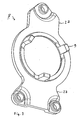
- Figur 1
- in einer perspektivischen, geschnittenen Darstellung eine Stelleinrichtung für einen Fahrzeugsitz,
- Figur 2
- eine Kappe der Stelleinrichtung nach
Figur 1 und - Figur 3
- ein Antriebselement der Stelleinrichtung nach
Figur 1 . - In
Figur 1 ist eine Stelleinrichtung 1 gezeigt, die ein Teil einer Sitzverstellung eines Kraftfahrzeugsitzes bildet. Die Funktion der Stelleinrichtung 1 entspricht grundsätzlich der Funktion des Klemmrollenschaltwerks nach derDE 198 54 931 A1 . Mit der Stelleinrichtung 1 nachFigur 1 wirkt eine weitere, nicht dargestellte Vorrichtung mit Freilaufeigenschaft zusammen, deren Funktion dem schaltbaren Klemmrollengesperre nach derDE 198 54 931 A1 entspricht. - Die Stelleinrichtung 1 weist ein Gehäuse 2 aus Metallblech auf, in welchem ein ebenfalls aus Metall gefertigter Außenring 3 als Abtriebselement drehbar gelagert ist. Der Außenring 3 ist von Abschnitten einer Ringwandung 4 umgeben, die Teile einer in
Figur 2 vollständig dargestellten Kappe 5 aus Kunststoff sind. Die Kappe 5 ist verdrehsicher auf dem Gehäuse 2 gehalten, wobei zwei Verdrehsicherungsnocken 6 der Kappe 5 in korrespondierende Aufnahmen 7 des spanlos geformten Gehäuses 2 eingreifen. Zusätzlich zur Abdeckfunktion weist die Kappe 5 noch weitere, untenstehend näher erläuterte Funktionen auf. - Als Antriebselement 8 der Stelleinrichtung 1 ist eine in
Figur 3 im Detail dargestellte Schaltscheibe vorgesehen. Die Schaltscheibe 8 ist als Stanzbiegeteil wie das Gehäuse 2 aus Blech gefertigt und weist drei einstückig angeformte Schaltfinger 9 auf, die auch inFigur 1 sichtbar sind und sich parallel zur Achse A des Antriebselementes 8 sowie des Abtriebselementes 3 erstrecken. In nicht dargestellter Weise ist an der als Antriebselement fungierenden Schaltscheibe 8 ein Hebel zur manuellen Betätigung der Stelleinrichtung 1 befestigt. - Zentral innerhalb der Stelleinrichtung 1 befindet sich ein Bolzen 10, dessen Symmetrieachse die Drehachse A des Antriebselementes 8 sowie des Abtriebselementes 3 definiert. Um den Bolzen 10 sind koaxial zum Außenring 3 und radial innerhalb von diesem zwei jeweils dreiflügelige Klemmscheiben 11, 12 drehbar. Hierbei befinden sich die insgesamt sechs Flügel 13, 14 der Klemmscheiben 11, 12 im Wesentlichen in einer gemeinsamen, normal zur Achse A angeordneten Ebene, wobei sich in Umfangsrichtung stets ein Flügel 13 der ersten Klemmscheibe 11 und ein Flügel 14 der zweiten Klemmscheibe 12 abwechseln. Zwischen benachbarten Flügeln 13, 14 sind insgesamt drei Aussparungen 15 gebildet, in welche die Schaltfinger 9 des Antriebselementes 8 eingreifen. Bei einer Verschwenkung des Antriebselementes 8 aus der dargestellten Neutralstellung heraus wird somit eine der Klemmscheiben 11, 12 in die entsprechende Drehrichtung mitgenommen.
- Die Klemmscheiben 11, 12 sind zwischen das Antriebselement 8 und den Außenring 3 geschaltete Antriebsteile, die die Übertragung einer Drehbewegung in wählbarer Richtung ermöglichen. Zur Herstellung des Kraftflusses zwischen einer Klemmscheibe 11, 12 und dem Außenring 3 weist jeder Flügel 13, 14 eine Klemmfläche 16 auf, auf der eine an der Innenseite des Außenrings 3 anliegende Klemmrolle 17 geführt ist. Mittels einer Freilauffeder 18, die als Schraubenfeder ausgebildet und zwischen einem sich bis zum Außenring 3 etwa in radialer Richtung erstreckenden Arm 19 des Flügels 13, 14 und der Klemmrolle 17 eingespannt ist, wird jede Klemmrolle 17 mit einer Kraft in Richtung zur Klemmposition beaufschlagt. Die Klemmflächen 16 sind derart ausgebildet, dass bei feststehendem Außenring 3 die Flügel 13, 14 in Richtung zur dargestellten Neutralposition schwenkbar, nicht jedoch aus dieser Position heraus bewegbar sind.
- Um die Klemmscheiben 11, 12 permanent mit einer Kraft in Richtung zur dargestellten Neutralposition zu beaufschlagen, sind zwischen die den Aussparungen 15 abgewandten Seiten der Flügel 13 ,14 insgesamt drei Rückstellfedern 20 in Form von Schraubenfedern eingespannt, wobei die von den Rückstellfedem 20 auf die Klemmscheiben 11, 12 ausgeübte Kraft die von den Freilauffedern 18 ausgeübte Kraft weit übersteigt. Die als Druckfedern ausgebildeten Rückstellfedern 20 werden komprimiert, wenn eine der Klemmscheiben 11, 12 durch Verschwenkung der Schaltscheibe 8 aus der Normalposition heraus gedreht wird. Am Arm 19 jedes Flügels 13, 14 befindet sich im an den Außenring 3 grenzenden Bereich eine Haltekante 21 als Haltekontur für die Rückstellfeder 20, die sicherstellt, dass die Rückstellfeder 20 während der gesamten möglichen Schwenkbewegung der Klemmscheibe 11, 12 nicht mit dem Außenring 3 in Kontakt kommt. Auf diese Weise werden Geräusche durch etwaige schabende Bewegungen vermieden.
- Wird eine der Klemmscheiben 11, 12 verschwenkt, so soll die andere Klemmscheibe 12, 11 hierbei in konstanter Winkelposition gehalten werden. Um dies zu erreichen, weist die Kappe 5 drei Spreiznocken 22 auf, welche, in Neutralposition an die Schaltfinger 9 angrenzend, teilweise in die Aussparungen 15 eingreifen. Die in Umfangsrichtung gemessene Breite desjenigen Bereichs einer Spreiznocke 22, der in die Aussparung 15 eingreift, entspricht der Breite des Schaltfingers 9. Solange sich die Stelleinrichtung 1 in Normalposition befindet, liegen Absätze 23 der Flügel 13, 14 sowohl am Schaltfinger 9 als auch an Anschlägen 24 der Spreiznocke 22 an. Die Absätze 23 bilden dabei sich etwa in radialer Richtung erstreckende Begrenzungen der Aussparung 15.
- Wird nun der Schaltfinger 9 und damit eine der Klemmscheiben 11, 12 aus der Normal- oder Neutralposition heraus verschwenkt, so bleibt der Absatz 23 der anderen Klemmscheibe 12, 11 in unveränderter Anlage am Anschlag 24. Bei derjenigen Klemmscheibe 11, 12, die aus der Neutralposition heraus verschwenkt wird, befindet sich die Klemmrolle 17 in Klemmposition, so dass der Außenring 3 mit dieser Klemmscheibe 11, 12 mitgedreht wird. Gleichzeitig muss verhindert werden, dass ein Kraftschluss zwischen der anderen Klemmscheibe 12, 11 und dem Außenring 3 gebildet wird. Zu diesem Zweck weist jede Spreiznocke 22 im radial äußeren, an den Außenring 3 grenzenden Bereich, einen Abstandshalter 25 mit zwei einander in Umfangsrichtung abgewandten Anlageflächen 26 für jeweils eine Klemmrolle 17 auf. Die Anlagefläche 26 an der Oberfläche der Spreiznocke 22 stellt sicher, dass die an der Anlagefläche 26 anliegende Klemmrolle 17 soweit aus der Klemmposition verdrängt ist, dass bei einer Verdrehung des Außenrings 3, die die Klemmrolle 17 tendenziell zur Spreiznocke 22 hin drückt, kein Kraftfluss zwischen dem Außenring 3 und der Klemmfläche 16, auf welcher sich die Klemmrolle 17 befindet, aufgebaut wird.
- Um eine nahezu spielfreie Betätigung der Stelleinrichtung 1 ohne Umschaltverluste zu ermöglichen, sind in Neutralstellung der Schaltscheibe 8 die beidseitig des Abstandshalters 25 auf verschiedenen Flügeln 13, 14 angeordneten Klemmrollen 17 nahezu in Klemmposition. Bereits bei einer geringfügigen Verschwenkung einer der Klemmscheiben 11, 12 wird somit die Klemmposition erreicht, die ein Mitdrehen des Abtriebselementes 3 mit dem Antriebselement 8 bewirkt. Eine Verschwenkung der Klemmscheibe 11, 12 ist soweit möglich, bis einer der sich radial nach außen erstreckenden Längsabschnitte 27 der Schaltscheibe 8 an einer Gehäusekante 28 des Gehäuses 2 anliegt, wobei in diesem Zustand die Rückstellfedern 20 annähernd auf Block sind. Ein Zurückschwenken des Antriebselementes 8 in die Normalposition ist aus jeder Winkelposition heraus möglich, so dass die Stelleinrichtung 1 eine stufenlose Verstellung des Kraftfahrzeugsitzes ermöglicht.
- Zusammenfassend umfasst die Stelleinrichtung 1 ein schwenkbares, insbesondere manuell betätigbares, Antriebselement 8 sowie ein um dieselbe Achse A drehbares, in einem Gehäuse 2 gelagertes Abtriebselement 3 in Form eines Außenrings, wobei sich mehrere einstückig an das Antriebselement 8 angeformte Schaltfinger 9 parallel zur Achse A erstrecken, weiter zwei radial innerhalb des Außenrings 3 angeordnete, jeweils mehrere zur Führung von Klemmrollen 17 vorgesehene Klemmflächen 16 aufweisende, gegeneinander um die Achse A verschwenkbare, mehrflügelige Klemmscheiben 11, 12, zwischen welchen Aussparungen 15 gebildet sind, in die jeweils einer der Schaltfinger 9 eingreift, sowie eine auf dem Gehäuse 2 gehaltene Kappe 5, welche mehrere Spreiznocken 22 aufweist, wobei jede Spreiznocke 22 sowohl einen Abstandshalter 25 zwischen zwei auf benachbarten Klemmflächen 16 angeordneten Klemmrollen 17 als auch jeweils einen Anschlag 24 für die Klemmscheiben 11, 12 bildet. Hierbei ist die Vielzahl der durch die Kappe 5 realisierten Funktionen von besonderem Vorteil. Weiterhin ist von Vorteil, dass die Schaltscheibe 8 keinerlei Durchstanzungen oder sonstige Öffnungen aufweist und damit besonders stabil ist. Ebenso weist die im Spritzgussverfahren aus Kunststoff gefertigte Kappe 5 keine Öffnungen auf. Insgesamt ist der Verstellmechanismus der Stelleinrichtung 1 vollständig gekapselt.
-
- 1
- Stelleinrichtung
- 2
- Gehäuse
- 3
- Abtriebselement, Außenring
- 4
- Ringwandung
- 5
- Kappe
- 6
- Verdrehsicherungsnocke
- 7
- Aufnahme
- 8
- Antriebselement, Schaltscheibe
- 9
- Schaltfinger
- 10
- Bolzen
- 11
- Klemmscheibe
- 12
- Klemmscheibe
- 13
- Flügel
- 14
- Flügel
- 15
- Aussparung
- 16
- Klemmfläche
- 17
- Klemmrolle
- 18
- Freilauffeder
- 19
- Arm
- 20
- Rückstellfeder
- 21
- Haltekontur
- 22
- Spreiznocke
- 23
- Absatz
- 24
- Anschlag
- 25
- Abstandshalter
- 26
- Anlagefläche
- 27
- Längsabschnitt
- 28
- Gehäusekante
- A
- Achse
Claims (8)
- Stelleinrichtung (1), insbesondere zur Verstellung eines Fahrzeugsitzes, mit- einem Gehäuse (2), in welchem ein Außenring (3) als Abtriebselement drehbar gelagert ist,- einem koaxial zum Außenring (3) angeordneten, schwenkbaren Antriebselement (8), an welches mehrere sich parallel zur Achse (A) des Antriebselementes (8) sowie des Abtriebselementes (3) erstreckende Schaltfinger (9) einstückig angeformt sind,- zwei radial innerhalb des Außenrings (3) und koaxial zu diesem angeordnete, gegeneinander verschwenkbare, mehrflügelige Klemmscheiben (11,12), wobei jeweils zwischen einem Flügel (13) der ersten Klemmscheibe (11) und einem Flügel (14) der zweiten Klemmscheibe (12) eine Aussparung (15), in welche einer der Schaltfinger (9) eingreift, gebildet ist, und wobei jeder Flügel (13,14) eine Klemmfläche (16) aufweist,- mehreren zwischen den Klemmflächen (16) und dem Außenring (3) geführten Klemmrollen (17),- einer normal zur Achse (A) angeordneten, nicht rotierbar auf dem Gehäuse (2) gehaltenen Kappe (5), welche eine der Anzahl der Schaltfinger (9) entsprechende Anzahl an Spreiznocken (22) aufweist, wobei jede Spreiznocke (22) sowohl einen Abstandshalter (25) zwischen zwei auf benachbarten Klemmflächen (16) angeordneten Klemmrollen (17) als auch jeweils einen Anschlag (24) für die diese Klemmflächen (16) aufweisenden Flügel (13,14) der Klemmscheiben (11,12) bildet.
- Stelleinrichtung nach Anspruch 1, gekennzeichnet durch eine zwischen jeweils einem Flügel (13,14) bei der Klemmscheiben eingespannte Rückstellfeder (20).
- Stelleinrichtung nach Anspruch 2, dadurch gekennzeichnet, dass die Rückstellfeder (20) als Schraubenfeder ausgebildet ist.
- Stelleinrichtung nach Anspruch 2 oder 3, dadurch gekennzeichnet, dass die Rückstellfeder (20) mittels jeweils einer Haltekontur (21), insbesondere eines Haltevorsprungs, derart an den Flügeln (13,14) der Klemmscheiben (11,12) gehalten ist, dass sie ohne Kontakt mit dem Abtriebselement (3) radial innerhalb des Abtriebselementes (3) geführt ist.
- Stelleinrichtung nach einem der Ansprüche 1 bis 4, dadurch gekennzeichnet, dass die Klemmscheiben (11,12) als Sintermetallteile gefertigt sind.
- Stelleinrichtung nach einem der Ansprüche 1 bis 5, dadurch gekennzeichnet, dass jede Klemmrolle (17) durch eine separate Freilauffeder (18), welche sich an einem Flügel abstützt (13,14), angefedert ist.
- Stelleinrichtung nach einem der Ansprüche 1 bis 6, dadurch gekennzeichnet, dass das Gehäuse (2) mindestens eine Aufnahme (7) für eine Verdrehsicherungsnocke (6) der Kappe (5) aufweist.
- Stelleinrichtung nach einem der Ansprüche 1 bis 7, dadurch gekennzeichnet, dass die Kappe (5) einstückig aus Kunststoff gefertigt ist.
Applications Claiming Priority (2)
| Application Number | Priority Date | Filing Date | Title |
|---|---|---|---|
| DE102005028307.1A DE102005028307B4 (de) | 2005-06-18 | 2005-06-18 | Stelleinrichtung, insbesondere zur Verstellung eines Fahrzeugsitzes |
| PCT/EP2006/004266 WO2006136234A1 (de) | 2005-06-18 | 2006-05-06 | Stelleinrichtung, insbesondere zur verstellung eines fahrzeugsitzes |
Publications (2)
| Publication Number | Publication Date |
|---|---|
| EP1896745A1 EP1896745A1 (de) | 2008-03-12 |
| EP1896745B1 true EP1896745B1 (de) | 2009-07-22 |
Family
ID=36597186
Family Applications (1)
| Application Number | Title | Priority Date | Filing Date |
|---|---|---|---|
| EP06724750A Expired - Lifetime EP1896745B1 (de) | 2005-06-18 | 2006-05-06 | Stelleinrichtung, insbesondere zur verstellung eines fahrzeugsitzes |
Country Status (4)
| Country | Link |
|---|---|
| EP (1) | EP1896745B1 (de) |
| AT (1) | ATE437310T1 (de) |
| DE (2) | DE102005028307B4 (de) |
| WO (1) | WO2006136234A1 (de) |
Families Citing this family (3)
| Publication number | Priority date | Publication date | Assignee | Title |
|---|---|---|---|---|
| DE102007010859A1 (de) * | 2007-03-01 | 2008-09-04 | Brose Fahrzeugteile Gmbh & Co. Kommanditgesellschaft, Hallstadt | Getriebe einer Antriebsvorrichtung eines Verstellsystems in einem Kraftfahrzeug |
| DE102010043825B4 (de) * | 2010-10-08 | 2023-07-27 | Keiper Seating Mechanisms Co., Ltd. | Klemmrollenfreilauf für eine Verstellvorrichtung in einem Kraftfahrzeug |
| DE102013215073B3 (de) * | 2013-08-01 | 2014-08-28 | Schaeffler Technologies Gmbh & Co. Kg | Schrittschaltwerk |
Family Cites Families (8)
| Publication number | Priority date | Publication date | Assignee | Title |
|---|---|---|---|---|
| DE8025286U1 (de) * | 1982-03-18 | Keiper Automobiltechnik Gmbh & Co Kg, 5630 Remscheid | Drehgelenk, insbesondere für Sitze mit verstellbarer Lehne | |
| US3216766A (en) * | 1962-05-14 | 1965-11-09 | Rockwell Standard Co | Infinite positional adjustment and one-way lock mechanism |
| DE3028539A1 (de) * | 1980-07-28 | 1982-02-25 | Alfred Teves Gmbh, 6000 Frankfurt | Stufenlos verstellbarer gelenkbeschlag, insbesondere fuer kraftfahrzeugsitze |
| US4313638A (en) * | 1980-07-30 | 1982-02-02 | Rockwell International Corporation | Infinitely variable seat recliner mechanism |
| DE9315132U1 (de) * | 1993-10-06 | 1993-12-23 | INA Wälzlager Schaeffler KG, 91074 Herzogenaurach | Drehgelenk |
| DE9408426U1 (de) * | 1994-05-24 | 1995-06-29 | Schwarzbich, Jörg, 33615 Bielefeld | Freilaufbremse |
| DE19854931A1 (de) * | 1998-11-27 | 2000-05-31 | Schaeffler Waelzlager Ohg | Stelleinrichtung, insbesondere zur Verstellung eines Kraftfahrzeugsitzes |
| FR2792264B1 (fr) * | 1999-04-16 | 2001-06-15 | Faure Bertrand Equipements Sa | Mecanisme de reglage irreversible |
-
2005
- 2005-06-18 DE DE102005028307.1A patent/DE102005028307B4/de not_active Expired - Fee Related
-
2006
- 2006-05-06 WO PCT/EP2006/004266 patent/WO2006136234A1/de not_active Ceased
- 2006-05-06 DE DE502006004315T patent/DE502006004315D1/de not_active Expired - Fee Related
- 2006-05-06 AT AT06724750T patent/ATE437310T1/de active
- 2006-05-06 EP EP06724750A patent/EP1896745B1/de not_active Expired - Lifetime
Also Published As
| Publication number | Publication date |
|---|---|
| ATE437310T1 (de) | 2009-08-15 |
| WO2006136234A1 (de) | 2006-12-28 |
| DE102005028307A1 (de) | 2006-12-21 |
| DE502006004315D1 (de) | 2009-09-03 |
| DE102005028307B4 (de) | 2016-09-15 |
| EP1896745A1 (de) | 2008-03-12 |
Similar Documents
| Publication | Publication Date | Title |
|---|---|---|
| EP0751032B1 (de) | Verstellvorrichtung | |
| DE3342497C2 (de) | ||
| DE10196484B4 (de) | Vorrichtung zum Sperren der Zahnräder einer Kraftübertragung | |
| EP1725437B1 (de) | Vorrichtung zum sperren der lenkspindel eines kraftfahrzeugs | |
| EP1939480B1 (de) | Schaltbarer Freilauf | |
| DE69620339T2 (de) | Fahrzeugstürstelltrieb | |
| DE102007010078A1 (de) | Verstellbeschlag für eine Kraftfahrzeugkomponente und Verfahren zur Sicherung der Arretierung eines Verstellbeschlags | |
| EP1284447B1 (de) | Schwenkbeschlag | |
| WO2010133538A1 (de) | Rastbeschlag mit einem einlegering | |
| DE60111004T2 (de) | Stellantrieb | |
| EP1520114B1 (de) | Druckstück mit einem rastelement | |
| WO2000075534A1 (de) | Beidseitig wirkender antrieb für verstellvorrichtungen | |
| DE10001158B4 (de) | Dämpferscheibenanordnung | |
| EP2748028B1 (de) | Verstellbeschlag mit einem axialsperrsystem zur ablaufsicherung | |
| EP0967350B1 (de) | Elektromotorischer Stellantrieb für ein Kraftfahrzeugschloss | |
| DE102005028307B4 (de) | Stelleinrichtung, insbesondere zur Verstellung eines Fahrzeugsitzes | |
| DE19646231A1 (de) | Nadellager | |
| DE102009002478A1 (de) | Ver- und Feststellvorrichtung eines Verstellbeschlages | |
| DE202015103313U1 (de) | Sitzversteller | |
| WO2007074026A2 (de) | Verriegelungseinheit, insbesondere für eine überlagerungslenkung | |
| WO2022073924A1 (de) | Gurtaufroller für einen fahrzeug-sicherheitsgurt | |
| EP3678603B1 (de) | Klemmrollengesperre | |
| EP2597229B1 (de) | Kupplungsteil, Bolzeneinrichtung, Rückstellmechanismus, Zylindergehäuse, Zylindereinrichtung, Schließzylinder und Einsteckschloss sowie ein Rückstell- und ein Montageverfahren hierzu | |
| DE10260548B4 (de) | Antrieb für einen Fahrzeugsitzeinsteller | |
| DE102023101988A1 (de) | Einrichtung zum Verstellen der Neigung einer Rückenlehne in Bezug auf eine Sitzfläche eines Sitzes |
Legal Events
| Date | Code | Title | Description |
|---|---|---|---|
| PUAI | Public reference made under article 153(3) epc to a published international application that has entered the european phase |
Free format text: ORIGINAL CODE: 0009012 |
|
| 17P | Request for examination filed |
Effective date: 20080118 |
|
| AK | Designated contracting states |
Kind code of ref document: A1 Designated state(s): AT BE BG CH CY CZ DE DK EE ES FI FR GB GR HU IE IS IT LI LT LU LV MC NL PL PT RO SE SI SK TR |
|
| DAX | Request for extension of the european patent (deleted) | ||
| GRAP | Despatch of communication of intention to grant a patent |
Free format text: ORIGINAL CODE: EPIDOSNIGR1 |
|
| GRAS | Grant fee paid |
Free format text: ORIGINAL CODE: EPIDOSNIGR3 |
|
| GRAA | (expected) grant |
Free format text: ORIGINAL CODE: 0009210 |
|
| AK | Designated contracting states |
Kind code of ref document: B1 Designated state(s): AT BE BG CH CY CZ DE DK EE ES FI FR GB GR HU IE IS IT LI LT LU LV MC NL PL PT RO SE SI SK TR |
|
| REG | Reference to a national code |
Ref country code: GB Ref legal event code: FG4D Free format text: NOT ENGLISH |
|
| REG | Reference to a national code |
Ref country code: CH Ref legal event code: EP |
|
| REG | Reference to a national code |
Ref country code: IE Ref legal event code: FG4D |
|
| REF | Corresponds to: |
Ref document number: 502006004315 Country of ref document: DE Date of ref document: 20090903 Kind code of ref document: P |
|
| NLV1 | Nl: lapsed or annulled due to failure to fulfill the requirements of art. 29p and 29m of the patents act | ||
| PG25 | Lapsed in a contracting state [announced via postgrant information from national office to epo] |
Ref country code: ES Free format text: LAPSE BECAUSE OF FAILURE TO SUBMIT A TRANSLATION OF THE DESCRIPTION OR TO PAY THE FEE WITHIN THE PRESCRIBED TIME-LIMIT Effective date: 20091102 Ref country code: LT Free format text: LAPSE BECAUSE OF FAILURE TO SUBMIT A TRANSLATION OF THE DESCRIPTION OR TO PAY THE FEE WITHIN THE PRESCRIBED TIME-LIMIT Effective date: 20090722 Ref country code: FI Free format text: LAPSE BECAUSE OF FAILURE TO SUBMIT A TRANSLATION OF THE DESCRIPTION OR TO PAY THE FEE WITHIN THE PRESCRIBED TIME-LIMIT Effective date: 20090722 Ref country code: IS Free format text: LAPSE BECAUSE OF FAILURE TO SUBMIT A TRANSLATION OF THE DESCRIPTION OR TO PAY THE FEE WITHIN THE PRESCRIBED TIME-LIMIT Effective date: 20091122 Ref country code: SE Free format text: LAPSE BECAUSE OF FAILURE TO SUBMIT A TRANSLATION OF THE DESCRIPTION OR TO PAY THE FEE WITHIN THE PRESCRIBED TIME-LIMIT Effective date: 20090722 |
|
| PG25 | Lapsed in a contracting state [announced via postgrant information from national office to epo] |
Ref country code: NL Free format text: LAPSE BECAUSE OF FAILURE TO SUBMIT A TRANSLATION OF THE DESCRIPTION OR TO PAY THE FEE WITHIN THE PRESCRIBED TIME-LIMIT Effective date: 20090722 Ref country code: PL Free format text: LAPSE BECAUSE OF FAILURE TO SUBMIT A TRANSLATION OF THE DESCRIPTION OR TO PAY THE FEE WITHIN THE PRESCRIBED TIME-LIMIT Effective date: 20090722 Ref country code: LV Free format text: LAPSE BECAUSE OF FAILURE TO SUBMIT A TRANSLATION OF THE DESCRIPTION OR TO PAY THE FEE WITHIN THE PRESCRIBED TIME-LIMIT Effective date: 20090722 Ref country code: SI Free format text: LAPSE BECAUSE OF FAILURE TO SUBMIT A TRANSLATION OF THE DESCRIPTION OR TO PAY THE FEE WITHIN THE PRESCRIBED TIME-LIMIT Effective date: 20090722 |
|
| REG | Reference to a national code |
Ref country code: IE Ref legal event code: FD4D |
|
| PG25 | Lapsed in a contracting state [announced via postgrant information from national office to epo] |
Ref country code: BG Free format text: LAPSE BECAUSE OF FAILURE TO SUBMIT A TRANSLATION OF THE DESCRIPTION OR TO PAY THE FEE WITHIN THE PRESCRIBED TIME-LIMIT Effective date: 20091022 Ref country code: PT Free format text: LAPSE BECAUSE OF FAILURE TO SUBMIT A TRANSLATION OF THE DESCRIPTION OR TO PAY THE FEE WITHIN THE PRESCRIBED TIME-LIMIT Effective date: 20091122 |
|
| PG25 | Lapsed in a contracting state [announced via postgrant information from national office to epo] |
Ref country code: DK Free format text: LAPSE BECAUSE OF FAILURE TO SUBMIT A TRANSLATION OF THE DESCRIPTION OR TO PAY THE FEE WITHIN THE PRESCRIBED TIME-LIMIT Effective date: 20090722 Ref country code: CZ Free format text: LAPSE BECAUSE OF FAILURE TO SUBMIT A TRANSLATION OF THE DESCRIPTION OR TO PAY THE FEE WITHIN THE PRESCRIBED TIME-LIMIT Effective date: 20090722 Ref country code: RO Free format text: LAPSE BECAUSE OF FAILURE TO SUBMIT A TRANSLATION OF THE DESCRIPTION OR TO PAY THE FEE WITHIN THE PRESCRIBED TIME-LIMIT Effective date: 20090722 Ref country code: IE Free format text: LAPSE BECAUSE OF FAILURE TO SUBMIT A TRANSLATION OF THE DESCRIPTION OR TO PAY THE FEE WITHIN THE PRESCRIBED TIME-LIMIT Effective date: 20090722 Ref country code: EE Free format text: LAPSE BECAUSE OF FAILURE TO SUBMIT A TRANSLATION OF THE DESCRIPTION OR TO PAY THE FEE WITHIN THE PRESCRIBED TIME-LIMIT Effective date: 20090722 |
|
| RAP2 | Party data changed (patent owner data changed or rights of a patent transferred) |
Owner name: SCHAEFFLER TECHNOLOGIES GMBH & CO. KG |
|
| PLBE | No opposition filed within time limit |
Free format text: ORIGINAL CODE: 0009261 |
|
| STAA | Information on the status of an ep patent application or granted ep patent |
Free format text: STATUS: NO OPPOSITION FILED WITHIN TIME LIMIT |
|
| PG25 | Lapsed in a contracting state [announced via postgrant information from national office to epo] |
Ref country code: SK Free format text: LAPSE BECAUSE OF FAILURE TO SUBMIT A TRANSLATION OF THE DESCRIPTION OR TO PAY THE FEE WITHIN THE PRESCRIBED TIME-LIMIT Effective date: 20090722 |
|
| 26N | No opposition filed |
Effective date: 20100423 |
|
| PG25 | Lapsed in a contracting state [announced via postgrant information from national office to epo] |
Ref country code: GR Free format text: LAPSE BECAUSE OF FAILURE TO SUBMIT A TRANSLATION OF THE DESCRIPTION OR TO PAY THE FEE WITHIN THE PRESCRIBED TIME-LIMIT Effective date: 20091023 |
|
| BERE | Be: lapsed |
Owner name: SCHAEFFLER K.G. Effective date: 20100531 |
|
| PG25 | Lapsed in a contracting state [announced via postgrant information from national office to epo] |
Ref country code: MC Free format text: LAPSE BECAUSE OF NON-PAYMENT OF DUE FEES Effective date: 20100531 |
|
| REG | Reference to a national code |
Ref country code: CH Ref legal event code: PL |
|
| GBPC | Gb: european patent ceased through non-payment of renewal fee |
Effective date: 20100506 |
|
| REG | Reference to a national code |
Ref country code: FR Ref legal event code: ST Effective date: 20110131 |
|
| PG25 | Lapsed in a contracting state [announced via postgrant information from national office to epo] |
Ref country code: LI Free format text: LAPSE BECAUSE OF NON-PAYMENT OF DUE FEES Effective date: 20100531 Ref country code: CH Free format text: LAPSE BECAUSE OF NON-PAYMENT OF DUE FEES Effective date: 20100531 |
|
| PG25 | Lapsed in a contracting state [announced via postgrant information from national office to epo] |
Ref country code: BE Free format text: LAPSE BECAUSE OF NON-PAYMENT OF DUE FEES Effective date: 20100531 |
|
| PG25 | Lapsed in a contracting state [announced via postgrant information from national office to epo] |
Ref country code: DE Free format text: LAPSE BECAUSE OF NON-PAYMENT OF DUE FEES Effective date: 20101201 |
|
| PG25 | Lapsed in a contracting state [announced via postgrant information from national office to epo] |
Ref country code: FR Free format text: LAPSE BECAUSE OF NON-PAYMENT OF DUE FEES Effective date: 20100531 |
|
| PG25 | Lapsed in a contracting state [announced via postgrant information from national office to epo] |
Ref country code: GB Free format text: LAPSE BECAUSE OF NON-PAYMENT OF DUE FEES Effective date: 20100506 |
|
| PG25 | Lapsed in a contracting state [announced via postgrant information from national office to epo] |
Ref country code: CY Free format text: LAPSE BECAUSE OF FAILURE TO SUBMIT A TRANSLATION OF THE DESCRIPTION OR TO PAY THE FEE WITHIN THE PRESCRIBED TIME-LIMIT Effective date: 20090722 |
|
| PG25 | Lapsed in a contracting state [announced via postgrant information from national office to epo] |
Ref country code: LU Free format text: LAPSE BECAUSE OF NON-PAYMENT OF DUE FEES Effective date: 20100506 Ref country code: HU Free format text: LAPSE BECAUSE OF FAILURE TO SUBMIT A TRANSLATION OF THE DESCRIPTION OR TO PAY THE FEE WITHIN THE PRESCRIBED TIME-LIMIT Effective date: 20100123 |
|
| PG25 | Lapsed in a contracting state [announced via postgrant information from national office to epo] |
Ref country code: TR Free format text: LAPSE BECAUSE OF FAILURE TO SUBMIT A TRANSLATION OF THE DESCRIPTION OR TO PAY THE FEE WITHIN THE PRESCRIBED TIME-LIMIT Effective date: 20090722 |
|
| REG | Reference to a national code |
Ref country code: AT Ref legal event code: MM01 Ref document number: 437310 Country of ref document: AT Kind code of ref document: T Effective date: 20110506 |
|
| PG25 | Lapsed in a contracting state [announced via postgrant information from national office to epo] |
Ref country code: AT Free format text: LAPSE BECAUSE OF NON-PAYMENT OF DUE FEES Effective date: 20110506 |
|
| PGFP | Annual fee paid to national office [announced via postgrant information from national office to epo] |
Ref country code: IT Payment date: 20160523 Year of fee payment: 11 |
|
| PG25 | Lapsed in a contracting state [announced via postgrant information from national office to epo] |
Ref country code: IT Free format text: LAPSE BECAUSE OF NON-PAYMENT OF DUE FEES Effective date: 20170506 |
|
| P01 | Opt-out of the competence of the unified patent court (upc) registered |
Effective date: 20230523 |