EP1895243B1 - Klimaanlage und Steuerung dafür - Google Patents
Klimaanlage und Steuerung dafür Download PDFInfo
- Publication number
- EP1895243B1 EP1895243B1 EP07017027.9A EP07017027A EP1895243B1 EP 1895243 B1 EP1895243 B1 EP 1895243B1 EP 07017027 A EP07017027 A EP 07017027A EP 1895243 B1 EP1895243 B1 EP 1895243B1
- Authority
- EP
- European Patent Office
- Prior art keywords
- air conditioning
- unit
- conditioning system
- controller
- indoor units
- Prior art date
- Legal status (The legal status is an assumption and is not a legal conclusion. Google has not performed a legal analysis and makes no representation as to the accuracy of the status listed.)
- Not-in-force
Links
Images


Classifications
-
- F—MECHANICAL ENGINEERING; LIGHTING; HEATING; WEAPONS; BLASTING
- F24—HEATING; RANGES; VENTILATING
- F24F—AIR-CONDITIONING; AIR-HUMIDIFICATION; VENTILATION; USE OF AIR CURRENTS FOR SCREENING
- F24F11/00—Control or safety arrangements
- F24F11/30—Control or safety arrangements for purposes related to the operation of the system, e.g. for safety or monitoring
-
- F—MECHANICAL ENGINEERING; LIGHTING; HEATING; WEAPONS; BLASTING
- F24—HEATING; RANGES; VENTILATING
- F24F—AIR-CONDITIONING; AIR-HUMIDIFICATION; VENTILATION; USE OF AIR CURRENTS FOR SCREENING
- F24F11/00—Control or safety arrangements
- F24F11/62—Control or safety arrangements characterised by the type of control or by internal processing, e.g. using fuzzy logic, adaptive control or estimation of values
-
- F—MECHANICAL ENGINEERING; LIGHTING; HEATING; WEAPONS; BLASTING
- F24—HEATING; RANGES; VENTILATING
- F24F—AIR-CONDITIONING; AIR-HUMIDIFICATION; VENTILATION; USE OF AIR CURRENTS FOR SCREENING
- F24F11/00—Control or safety arrangements
- F24F11/50—Control or safety arrangements characterised by user interfaces or communication
- F24F11/54—Control or safety arrangements characterised by user interfaces or communication using one central controller connected to several sub-controllers
Definitions
- the present invention relates to an air conditioning system installed in a large-scale building or the like, and a controller for the air conditioning system.
- a controller for an air conditioning system according to the preamble of independent claim 1 is known from US 2002/029096 A1 .
- a large number of air conditioning systems as described above are used in combination because the number of rooms is increased, thereby constructing a large-scale air conditioning system having several hundreds to one thousand or more (hereinafter referred to as "multiple air conditioning system for buildings") to air-condition each room in the building.
- the switching operation between the cooling operation and the heating operation is carried out every outdoor unit in the 2-way air conditioning system and every indoor unit in the 3-way air conditioning system. Therefore, it is impossible to switch the air conditioning operations of the respective rooms in the building all together at the turn of the seasons or the like.
- the present invention has been implemented in view of the foregoing situation, and has an object of the present invention is to provide an air conditioning system that can perform switching of cooling operation or heating operation all together, and a controller for the air conditioning system.
- an air conditioning system including at least one first air conditioning system in which an outdoor unit is connected to plural indoor units through an inter-unit pipe and the plural indoor units are allowed to execute one of cooling operation and heating operation concurrently, at least one second air conditioning system in which an outdoor unit is connected to plural indoor units through an inter-unit pipe and the plural indoor units are allowed to execute both cooling operation and heating operation in mixture concurrently, and the above controller.
- first air conditioning system in which an outdoor unit is connected to plural indoor units through an inter-unit pipe and the plural indoor units are allowed to execute one of cooling operation and heating operation concurrently
- at least one second air conditioning system in which an outdoor unit is connected to plural indoor units through an inter-unit pipe and the plural indoor units are allowed to execute both cooling operation and heating operation in mixture concurrently
- the air conditioning system is equipped with the controller for concurrently transmitting a switching instruction signal for instructing switching of the air conditioning operation to cooling operation or heating operation to the first air conditioning system in which one of the cooling operation and the heating operation (i.e. , the same air-conditioning operation) can be concurrently performed by plural indoor units, and the second air conditioning system in which both the heating operation and the cooling operation (i.e., the different air-conditioning operations) are concurrently performed by the plural indoor units. Therefore, the switching operation to cooling operation or heating operation can be performed concurrently (all together) among the plural indoor units. Therefore, the work of switching the air conditioning operation at the turn of the seasons or the like can be facilitated.
- Fig. 1 is a diagram showing a multiple air conditioning system for a building as an air conditioning system according to an embodiment of the present invention.
- This multiple air conditioning system 1 is used to air-condition each room of a relatively-large scale building such as a commercial building, a hospital or the like, and it has a control computer 2 as a central control device and plural sub air conditioning systems 4 which are connected to the control computer 2 through a main communication line 3 so that communications can be performed therebetween.
- the main communication line 3 has plural (four in Fig. 1 ) communication adaptor operating lines 3A to 3D, and communication adaptors 5 are connected to the communication adaptor operating lines 3A to 3D.
- the upper limit number of the communication adaptors is equal to 31, for example.
- Each sub air conditioning system 4 is connected to each communication adaptor 5.
- Each sub air conditioning system 4 has a 2-way air conditioning system 7 (first air conditioning system) and a 3-way air conditioning system 8 (second air conditioning system) .
- the 2-way air conditioning system 7 is connected to each communication adaptor 5 through a sub communication line 6A
- the 3-way air conditioning system 8 is connected to each communication adaptor 5 through a sub communication line 6B, whereby the 2-way and 3-way air conditioning systems 7 and 8 can communicate with the control computer 2. It is needless to say that each sub air conditioning system 4 has only plural 2-way air conditioning systems or only plural 3-way air conditioning systems 8.
- the 2-way air conditioning system 7 is equipped with a plurality of (or one) outdoor units 15 each having a compressor and an outdoor heat exchanger and plural indoor units 25 each having an indoor heat exchanger which are connected to one another through an inter-unit pipe (not shown) comprising a high-pressure gas pipe, a low-pressure gas pipe and a liquid pipe.
- each outdoor unit 15 serves as a condenser and each indoor unit 25 serves as an evaporator.
- each outdoor unit 15 serves as an evaporator
- each indoor unit 25 serves as a condenser, whereby the respective indoor units 25 can carry out cooling operation or heating operation at the same time.
- Each outdoor unit 15 is provided with an outdoor control device 10.
- One of the outdoor control devices 10 serves as a master control device to control the other slave outdoor control devices 10.
- the master outdoor control device 10 gives an operation switching instruction to the other slave outdoor control devices 10, whereby the four-way valves (not shown) of the respective outdoor units 15 are switched and the air conditioning operations of the outdoor units 15 are switched all together.
- each indoor unit 25 is provided with an indoor control device 20, and each indoor control device 20 has a function of receiving an air conditioning request from a remote controller (not shown) set in a room and transmitting the air conditioning request through the sub communication line 6A to the outdoor control device 10.
- the 3-way air conditioning system 8 has a plurality of (or one) outdoor units 16 each having a compressor and an outdoor heat exchanger, and a plurality of indoor units 26 each having an indoor heat exchanger which are connected to one another through an inter-unit pipe (not shown) comprising a high-temperature and high-pressure gas refrigerant pipe (discharging pipe), an intermediate-temperature and intermediate-pressure liquid refrigerant pipe (liquid pipe) and a low-temperature and low-pressure gas refrigerant pipe (suction pipe), whereby each indoor unit 26 can individually perform cooling operation or heating operation, and thus cooling operation and heating operation can be performed in mixture in the respective indoor units 26.
- Each outdoor unit 16 and each indoor unit 26 are connected to the sub communication line 6B, whereby the communications can be performed therebetween.
- each indoor unit 26 is provided with a first opening/closing valve for connecting the gas refrigerant pipe (discharge pipe) and the liquid refrigerant pipe (liquid pipe) to the indoor heat exchanger, and a second opening/closing valve for connecting the liquid refrigerant pipe (liquid pipe) and the gas refrigerant pipe (suction pipe) to the indoor heat exchanger.
- the first opening/closing valve is set to an open state and the second opening/closing valve is set to a close state, whereby the indoor heat exchanger is connected to the discharge pipe and the liquid pipe and the indoor heat exchanger is made to function as a condenser.
- the first opening/closing valve Under cooling operation, the first opening/closing valve is set to a close state and the second opening/closing valve is set to an open state, whereby the indoor heat exchanger is connected to the liquid pipe and the suction pipe and the indoor heat exchanger is made to function as an evaporator.
- each indoor unit switches the open/close state of the first and second opening/closing valves, whereby the cooling operation or the heating operation can be individually performed every indoor unit.
- each outdoor unit 16 functions as is determined on the basis of the ratio of the number of the indoor units 26 carrying out cooling operation (cooling capacity) and the number of the indoor units 26 carrying out heating operation (heating capacity) in consideration of the operation efficiency.
- cooling capacity cooling capacity
- heating capacity heating capacity
- each outdoor unit 16 is provided with an outdoor control device 11, and one of the outdoor control devices functions as a master outdoor control device to control the other slave outdoor control devices to make each outdoor unit 16 function as a condenser or an evaporator.
- Each indoor unit 26 is provided with an indoor control device 21.
- Each indoor control device 21 has a function of receiving an air conditioning request from a remote controller (not shown) installed in the room to switch the open/close state of the first and second opening/closing valves and carry out cooling operation or heating operation, or transmitting a power request to the outdoor control device 11 through the sub communication line 6B.
- the control computer 2 executes lump-switching control of the air-conditioning operation to the cooling operation or heating operation in the 2-way air conditioning system 7 and the 3-way air conditioning system 8 of each sub air conditioning system 4.
- the construction of the control computer 2 will be described in detail below.
- Fig. 2 is a block diagram showing the functional construction of the control computer 2.
- the control computer 2 is constructed by using a general computer system, and it has a controller 30 as a controlling/operating unit, an interface portion 31 as a connection interface of the main communication line 3 and a storage unit 32 for storing various kinds of programs and data.
- the storage unit 32 contains an air condition control program 100 for controlling the switching of the air conditioning operation to cooling operation or heating operation in each sub air conditioning system 4 , and air conditioning system basic data 102.
- the air conditioning system basic data 102 contain indoor unit data 104 as basic data of the respective indoor units 25 and 26 of the 2-way air conditioning system and the 3-way air conditioning system 8 of each sub air conditioning system 4, and outdoor unit data 106 as basic data of the respective outdoor units 15 and 16.
- the indoor unit data 104 In the indoor unit data 104, the type of the air conditioning system (2-way or 3-way) to which each indoor unit 25, 26 belongs, the installation place (appellation or room name), the presence or absence of the remote controller (RC), the indoor unit address (inherent identification number), etc. are associated with one another every indoor unit, and further an indoor unit group is defined for the indoor units 26 belonging to the 3-way air conditioning system 8.
- the indoor unit group is used to collectively control plural indoor units 26 as a group, and an indoor address of indoor units 26 belonging to each group is registered every indoor unit group.
- the indoor unit data 104 contains concentration control information (center control information) with which the control computer 2 controls specific settings (for example, setting of temperature setting, setting of air flow direction, setting of air flow amount, etc.) to the indoor units 25, 26 and the operation from the remote controller to the specific settings is prohibited.
- concentration control information is classified into plural concentrated control modes in accordance with the kinds of the specific settings which are prohibited from being operated from the remote controller, and the concentrated control mode to which each indoor unit 25, 26 under concentrated control is classified is recorded.
- the outdoor unit data 106 contains the type (2-way or 3-way) of the air conditioning system to which each outdoor unit 15, 16 belongs, an outdoor unit address (inherent identification number), and also an indoor unit address of each indoor unit 25 connected to the outdoor unit 15 in the case of the 2-way air conditioning system 7 are associated with one another every outdoor unit 15, 16.
- the control computer 2 transmits a switching instruction signal to the cooling operation or the heating operation through the main communication line 3 to each outdoor unit 15 (or the outdoor unit 15 having the outdoor control device 10 serving as the master) of all the 2-way air conditioning systems 7 and each indoor unit 26 of all ht e3-way air conditioning systems 8.
- each outdoor unit 15 switches the four-way valve (not shown) or the like to switch the air conditioning operation of the indoor unit 25, and in the 3-way air conditioning systems 7, each indoor unit 26 switches the open/close states of the first and second opening/closing valves to switch the air-conditioning operation, whereby the air conditioning operations of all the indoor units 25, 26 of the multiple air conditioning system 1 for buildings are collectively switched all together.
- An operation switching and setting screen 110 with a data inputting/registering unit is prepared as an user interface for switching the air conditioning operation, and this operation switching and setting screen 110 will be described with reference to Fig. 3 .
- the operation switching and setting screen 110 is displayed on a monitor device 2A or the like which is equipped to the control computer 2, and it is provided with a concurrent switching instruction column 120 and a details setting column 121 as shown in Fig. 3 .
- the concurrent switching instruction column 120 is used to input an instruction of switching the air-conditioning operations of the respective indoor units 25, 26 concurrently or all together, and "concurrent switch to cooling (switch to cooling all together) " and “concurrent switch to heating (switch to heating all together)" can be selected.
- the details setting column 121 is used to preset a switching date (month and day) and a switching time (hour and minute) of the air-conditioning operation.
- a switching date for example, turn of the seasons
- a switching time for example, turn of the seasons
- the details setting column 121 is provided with an air conditioning setting item column for setting the setting temperature, the air flow velocity (strong or weak under cooling/heating operation), the air flow direction (a tilt angle of a louver), etc., and by carrying out setting on the air conditioning setting item column, the air conditioning setting instruction is transmitted to the indoor units 25, 26 at the switching date and hour concerned, whereby the setting of the air conditioning setting item column is reflected to the indoor units 25 and 26.
- the air conditioning operations of all the indoor units of the multiple air conditioning system 1 for buildings are switched all together (or concurrently).
- the operation switching and setting screen 110 is provided with an excluding unit setting column 122 for individually setting and registering indoor units 25, 26 which should be excluded from the air-conditioning operation switching control.
- the excluded unit setting column 122 On the excluded unit setting column 122 are displayed room name (installation place), an indoor unit address, information indicating which one of the 2-way air conditioning system 7 and the 3-way air conditioning system 8 each indoor unit 25, 26 belongs to, setting temperature, the air flow velocity, the air flow direction, the presence or absence of the remote controller (RC), an exclusion check column, etc. every indoor unit 25, 26 while these data are associated with each other.
- the switching instruction signal for switching the air conditioning operation is not transmitted to the ticked indoor units 25, 26, and thus they are excluded from the switching control.
- the air conditioning operations of the respective indoor units 26 are switched concurrently (all together) while keeping the compliance of setting of the indoor units 26 in the indoor unit group as the control group.
- the air conditioning operations of the indoor units to be excluded can be set on the details setting column 121. That is, the date of validating the exclusion from the air condition switching control (excluding date), the setting temperature of the indoor units 25, 26 to be excluded, the air flow velocity, the air flow direction, the concentrated control mode, etc. can be set on the details setting column 121.
- the indoor units 25, 26 which are indicated to be excluded can be operated under the air conditioning operation preset on the details setting column 121 only at the exclusion date.
- the operation switching and setting screen 110 is provided with an outdoor unit order button 123 for displaying, in the order of the outdoor units 15, 16, the indoor units 25, 26 to be displayed on the exclusion unit setting column 122, and a control group button 124 for displaying indoor units every indoor group.
- the outdoor unit order button 123 is selected, and the whole 2-way air conditioning system whose indoor unit 25 is disposed at a desired installation place can be efficiently excluded from the air conditioning operation switching control while checking the installation place of the indoor unit 25 concerned.
- control group button 124 is selected, and the whole indoor unit group whose indoor unit 26 is disposed at a desired installation place can be efficiently excluded from the air conditioning operation switching control while checking the installation place of each indoor unit 26 of the outdoor unit group concerned.
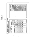
- the details setting column 121 is provided with a mode indicating column for indicating a mode as a preset of the details setting. As shown in Fig. 4 , this mode is set by operating the mode setting screen 130.
- the mode setting screen 130 is provided with a calendar 131 for setting a switching date, and an operation switching setting column 132 for indicating the air condition switching every plural modes.
- a desired mode is preset on the mode setting screen 130, whereby the preset is reflected by merely selecting the desired mode concerned on the details setting column 121, so that the setting can be facilitated.
- each of the operation switching and setting screen 110 and the mode setting screen 130 is provided with a display column for reporting abnormality which occurs in the multiple air conditioning system 1 for buildings at present.
- Various kinds of abnormality information received from the respective outdoor units 15 and 16 and the respective indoor units 25, 26 through the main communication line 3 by the control computer 2 is displayed on the display column.
- the control computer 2 emits an alarm buzzer from a sound source device (not shown) to quickly notify occurrence of the abnormality to a worker.
- control computer 2 transmits the switching instruction signal for instructing the switching of the air conditioning operation to the cooling operation or the heating operation to each sub air conditioning system 4 having the 2-way air conditioning system 7 and the 3-way air conditioning system 8 through the main communication line 3 all together (or concurrently). Therefore, the air conditioning operations of the indoor units 25, 26 for the multiple air conditioning system 1 for buildings can be collectively switched all together (concurrently).
- a day on which the air conditioning operation is switched to the cooling operation or the heating operation can be registered. Therefore, by registering turn of the seasons or the like in advance, the air conditioning operations of the indoor units can be switched all together on that day.
- the indoor units 25, 26 to be excluded from the air condition switching targets can be registered, and thus a desired operation can be continued for a specific room without switching the air conditioning operation of the specific room.
- the exclusion setting of the indoor units 25, 26 can be performed every outdoor unit 15 of the 2-way air conditioning system 7 or every indoor unit group of the 3-way air conditioning system 8. Furthermore, the installation place of each indoor unit 25, 26 can be checked, and thus only the indoor unit 25, 26 of a desired room can be efficiently excluded from the air condition switching targets.
- At least one of the air condition settings such as the setting temperature of the indoor units 25, 26, the setting of the air flow velocity, the setting of the air flow direction, the setting of the concentrated control mode can be registered, and thus the air conditioning settings can be collectively reflected to each indoor unit 25, 26 when the air conditioning operation is switched.
Landscapes
- Engineering & Computer Science (AREA)
- Chemical & Material Sciences (AREA)
- Combustion & Propulsion (AREA)
- Mechanical Engineering (AREA)
- General Engineering & Computer Science (AREA)
- Physics & Mathematics (AREA)
- Fuzzy Systems (AREA)
- Mathematical Physics (AREA)
- Signal Processing (AREA)
- Air Conditioning Control Device (AREA)
- Compression-Type Refrigeration Machines With Reversible Cycles (AREA)
Claims (7)
- Steuerung (30) für ein Klimaanlagensystem (1), das mindestens ein erstes Klimaanlagensystem (7), in dem eine Außeneinheit (15) mit mehreren Inneneinheiten (25) durch eine geräteübergreifende Leitung verbunden ist und die mehreren Inneneinheiten gleichzeitig entweder einen Kühlbetrieb oder einen Heizbetrieb ausführen dürfen, und mindestens ein zweites Klimaanlagensystem (8), in dem eine Außeneinheit (16) mit mehreren Inneneinheiten (26) durch eine geräteübergreifender Leitung verbunden ist und die mehreren Inneneinheiten gleichzeitig sowohl Kühlbetrieb als auch Heizbetrieb gemischt ausführen dürfen, einschließt, wobei die Steuerung durch eine Kommunikationsleitung (3) mit dem ersten und zweiten Klimaanlagensystem verbunden ist, sodass Kommunikation zwischen der Steuerung und sowohl dem ersten als auch dem zweiten Klimaanlagensystem durchgeführt werden kann,
die Steuerung ein Schaltanweisungssignal durch die Kommunikationsleitung gemeinsam an das erste und zweite Klimaanlagensystem überträgt, um die Umschaltung eines Klimaanlagenbetriebs auf Kühlbetrieb oder Heizbetrieb anzuweisen; und dadurch gekennzeichnet, dass
die Steuerung mit einer Ausschlusseinheitregistrierungseinheit zum Registrieren, an der Steuerung, von Inneneinheiten, die von Zieleinheiten des ersten und zweiten Klimaanlagensystems, die der Klimaanlagenumschaltung auf Kühlbetrieb oder Heizbetrieb auf Basis des Schaltanweisungssignals unterworfen werden sollten, ausgeschlossen werden sollen. - Klimaanlagensystem (1), das Folgendes umfasst:mindestens ein erstes Klimaanlagensystem (7), in dem eine Außeneinheit (15) mit mehreren Inneneinheiten (25) durch eine geräteübergreifende Leitung verbunden ist und die mehreren Inneneinheiten gleichzeitig entweder Kühlbetrieb oder Heizbetrieb ausführen dürfen;mindestens ein zweites Klimaanlagensystem (8), in dem eine Außeneinheit (16) mit mehreren Inneneinheiten (26) durch eine geräteübergreifende Leitung verbunden ist und die mehreren Inneneinheiten gleichzeitig sowohl Kühlbetrieb als auch Heizbetrieb gemischt ausführen dürfen; undeine Steuerung (30) gemäß Anspruch 1.
- Klimaanlagensystem gemäß Anspruch 2, wobei die Steuerung mit einer Datumregistrierungseinheit zum Registrieren, an der Steuerung, eines Datums, an dem das Schaltanweisungssignal zum Umschalten des Klimaanlagenbetriebs auf Kühlbetrieb oder Heizbetrieb übertragen wird.
- Klimaanlagensystem gemäß Anspruch 2, wobei das Klimaanlagensystem eine Anzahl von ersten Klimaanlagensystemen aufweist und die Steuerung mit einer Registrierungseinheit zum Registrieren, an der Steuerung, von ersten Klimaanlagensystemen, die von Zielklimaanlagensystemen, die der Klimaanlagenumschaltung auf Kühlbetrieb oder Heizbetrieb auf Basis des Schaltanweisungssignals unterworfen werden sollten, ausgeschlossen werden sollen, ausgerüstet ist, für jede Außeneinheit des ersten Klimaanlagensystems.
- Klimaanlagensystem gemäß Anspruch 2, wobei die Steuerung mit einer Speichereinheit (32) zum Speichern einer Anzahl von Inneneinheitengruppen, die durch Teilen der Inneneinheiten des zweiten Klimaanlagensystems alle mehrere Inneneinheiten erreicht wird, und einer Registrierungseinheit zum Registrieren, an der Steuerung, von Inneneinheitengruppen, die von Zielinneneinheitengruppen, die der Klimaanlagenumschaltung auf Kühlbetrieb oder Heizbetrieb auf Basis des Schaltanweisungssignals unterworfen werden sollten, ausgeschlossen werden sollen, ausgerüstet ist, für jede Inneneinheitengruppe.
- Klimaanlagensystem gemäß Anspruch 2, wobei die Steuerung mit einer Speichereinheit (32) zum Speichern eines Installationsortes für jede Inneneinheit des ersten und zweiten Klimaanlagensystems im Voraus und einer Registrierungseinheit zum Registrieren, an der Steuerung auf Basis des Installationsorts, einer Inneneinheit, die von Zielinneneinheiten, die der Klimaanlagenumschaltung auf Kühlbetrieb oder Heizbetrieb auf Basis des Schaltanweisungssignals unterworfen werden sollten, ausgeschlossen werden sollen, ausgerüstet ist.
- Klimaanlagensystem gemäß Anspruch 2, wobei die Steuerung mit einer Registrierungseinheit zum Registrieren an der Steuerung mindestens eines Einstellungswerts der Einstellung von Temperatur, einer Luftstromgeschwindigkeit, einer Luftstromrichtung und eines konzentrierten Steuermodus jeder Inneneinheit ausgerüstet ist und die Steuerung den Einstellungswert für jede Inneneinheit wiedergibt, wenn der Klimaanlagenbetrieb auf den Heizbetrieb oder den Kühlbetrieb umgeschaltet wird.
Applications Claiming Priority (1)
| Application Number | Priority Date | Filing Date | Title |
|---|---|---|---|
| JP2006236786A JP2008057893A (ja) | 2006-08-31 | 2006-08-31 | 空気調和システム及び空気調和システムの制御装置 |
Publications (3)
| Publication Number | Publication Date |
|---|---|
| EP1895243A2 EP1895243A2 (de) | 2008-03-05 |
| EP1895243A3 EP1895243A3 (de) | 2013-02-20 |
| EP1895243B1 true EP1895243B1 (de) | 2016-10-12 |
Family
ID=38656726
Family Applications (1)
| Application Number | Title | Priority Date | Filing Date |
|---|---|---|---|
| EP07017027.9A Not-in-force EP1895243B1 (de) | 2006-08-31 | 2007-08-30 | Klimaanlage und Steuerung dafür |
Country Status (4)
| Country | Link |
|---|---|
| US (1) | US7797953B2 (de) |
| EP (1) | EP1895243B1 (de) |
| JP (1) | JP2008057893A (de) |
| CN (1) | CN100554803C (de) |
Families Citing this family (11)
| Publication number | Priority date | Publication date | Assignee | Title |
|---|---|---|---|---|
| KR20080074378A (ko) * | 2007-02-08 | 2008-08-13 | 엘지전자 주식회사 | 멀티에어컨의 온도제한 방법 |
| JP5005010B2 (ja) * | 2009-09-03 | 2012-08-22 | 三菱電機株式会社 | 設備制御装置 |
| KR100980290B1 (ko) * | 2009-10-14 | 2010-09-07 | 주식회사 다원센추리 | 전력선 통신을 이용한 냉난방장치 |
| CN102762928B (zh) * | 2010-02-17 | 2015-09-09 | 三菱电机株式会社 | 空气调和系统 |
| WO2012172595A1 (ja) | 2011-06-14 | 2012-12-20 | 三菱電機株式会社 | 空調管理装置 |
| US9939824B2 (en) * | 2011-10-07 | 2018-04-10 | Honeywell International Inc. | Thermostat with remote access feature |
| KR101300259B1 (ko) * | 2011-10-10 | 2013-08-23 | 엘지전자 주식회사 | 공기 조화기, 이를 포함한 공기 조화 시스템 및 실외기 제어 방법 |
| CN104879899B (zh) * | 2015-06-09 | 2018-09-07 | 广东美的暖通设备有限公司 | 多联机空调系统及多联机空调系统的控制方法 |
| CN112368517B (zh) | 2018-06-13 | 2022-05-10 | 大金工业株式会社 | 空调系统 |
| US20230117125A1 (en) * | 2022-12-16 | 2023-04-20 | Munters Corporation | Methods and control systems for controlling fluid conditioning system including plural fluid conditioning units |
| CN117329653B (zh) * | 2023-09-25 | 2026-07-24 | 珠海格力电器股份有限公司 | 一种机组内机分组控制方法、装置、控制系统及空调机组 |
Family Cites Families (23)
| Publication number | Priority date | Publication date | Assignee | Title |
|---|---|---|---|---|
| US4809154A (en) * | 1986-07-10 | 1989-02-28 | Air Products And Chemicals, Inc. | Automated control system for a multicomponent refrigeration system |
| JP2804527B2 (ja) | 1989-07-24 | 1998-09-30 | 三洋電機株式会社 | 空気調和装置 |
| JPH0460332A (ja) * | 1990-06-28 | 1992-02-26 | Toshiba Corp | 空気調和装置 |
| US5279458A (en) * | 1991-08-12 | 1994-01-18 | Carrier Corporation | Network management control |
| JP3091541B2 (ja) * | 1991-11-18 | 2000-09-25 | 三洋電機株式会社 | 空気調和機の制御装置 |
| JPH0674496A (ja) * | 1992-08-25 | 1994-03-15 | Toshiba Corp | 空気調和機 |
| JP3113422B2 (ja) * | 1992-11-11 | 2000-11-27 | 三洋電機株式会社 | 空気調和機のアドレス自動設定方式 |
| SG43245A1 (en) * | 1993-04-09 | 1997-10-17 | Daikin Ind Ltd | Driving control device for air conditioner |
| JPH07286750A (ja) * | 1994-04-18 | 1995-10-31 | Daikin Ind Ltd | 空気調和装置の制御装置 |
| US5853123A (en) * | 1994-10-19 | 1998-12-29 | Daikin Industries, Ltd. | Signal transmission/reception device of air conditioner |
| JP3327158B2 (ja) * | 1997-02-07 | 2002-09-24 | 松下電器産業株式会社 | 多室形空気調和装置 |
| US6647317B2 (en) * | 2000-09-06 | 2003-11-11 | Hitachi Ltd | Air conditioner management system |
| US7127901B2 (en) * | 2001-07-20 | 2006-10-31 | Brooks Automation, Inc. | Helium management control system |
| US6978627B2 (en) * | 2002-01-31 | 2005-12-27 | Mitsubishi Denki Kabushiki Kaisha | Air conditioner control system, central remote controller, and facility controller |
| JP3742926B2 (ja) * | 2002-04-09 | 2006-02-08 | ダイキン工業株式会社 | 空調管理装置 |
| KR20040048186A (ko) * | 2002-12-02 | 2004-06-07 | 엘지전자 주식회사 | 멀티 에어컨의 중앙 제어 시스템 및 그 동작방법 |
| JP4129594B2 (ja) * | 2003-04-15 | 2008-08-06 | 株式会社日立製作所 | 空調システム |
| KR100565486B1 (ko) * | 2003-06-11 | 2006-03-30 | 엘지전자 주식회사 | 에어컨의 중앙제어 시스템 및 그 동작방법 |
| KR100529952B1 (ko) * | 2004-03-22 | 2005-11-22 | 엘지전자 주식회사 | 멀티에어컨의 중앙제어 시스템 및 그 동작방법 |
| KR100649599B1 (ko) * | 2004-03-22 | 2006-11-27 | 엘지전자 주식회사 | 다중지역 통합용 에어컨 시스템 |
| JP4552119B2 (ja) * | 2004-07-16 | 2010-09-29 | 清水建設株式会社 | マルチエアコンのデマンド制御システム |
| KR100629345B1 (ko) * | 2005-02-24 | 2006-09-29 | 엘지전자 주식회사 | 멀티 공조 중앙제어시스템 |
| US7584897B2 (en) * | 2005-03-31 | 2009-09-08 | Honeywell International Inc. | Controller system user interface |
-
2006
- 2006-08-31 JP JP2006236786A patent/JP2008057893A/ja active Pending
-
2007
- 2007-05-29 CN CNB2007101064157A patent/CN100554803C/zh not_active Expired - Fee Related
- 2007-08-29 US US11/847,086 patent/US7797953B2/en not_active Expired - Fee Related
- 2007-08-30 EP EP07017027.9A patent/EP1895243B1/de not_active Not-in-force
Also Published As
| Publication number | Publication date |
|---|---|
| US20080053122A1 (en) | 2008-03-06 |
| EP1895243A3 (de) | 2013-02-20 |
| JP2008057893A (ja) | 2008-03-13 |
| CN101135486A (zh) | 2008-03-05 |
| US7797953B2 (en) | 2010-09-21 |
| EP1895243A2 (de) | 2008-03-05 |
| CN100554803C (zh) | 2009-10-28 |
Similar Documents
| Publication | Publication Date | Title |
|---|---|---|
| US7797953B2 (en) | Air conditioning system and controller for the same | |
| US10871301B2 (en) | Air conditioner and control method thereof | |
| KR101517084B1 (ko) | 공기조화기용 제어장치 | |
| US20160025369A1 (en) | Air conditioning system | |
| EP1674804B1 (de) | Vorrichtung und Verfahren zur Überwachung einer Mehrzonen-Klimanlage | |
| KR20150011258A (ko) | 공기조화기 및 그 제어방법 | |
| CN103807975A (zh) | 用于控制空调的装置及其操作方法 | |
| JP5338693B2 (ja) | 空気調和システム | |
| KR101921537B1 (ko) | 공기조화기 시스템 | |
| JP2016151395A (ja) | 空気調和装置 | |
| KR101203559B1 (ko) | 그룹제어가 가능한 공기조화 시스템 및 그 동작방법 | |
| EP2538150B1 (de) | Klimatisierungssystem | |
| EP4075072B1 (de) | Klimaanlagensystem | |
| KR102206462B1 (ko) | 공기조화기 및 그 제어방법 | |
| KR102206463B1 (ko) | 공기조화기 및 그 제어방법 | |
| JP4300069B2 (ja) | 空気調和装置及びその制御方法 | |
| KR102199373B1 (ko) | 공기조화기 및 그 동작방법 | |
| KR20130022295A (ko) | 공기조화기 제어장치 및 이의 운전방법 | |
| US11913661B2 (en) | Air-conditioning system | |
| KR102205162B1 (ko) | 공기조화기 시스템 및 그 동작방법 | |
| JP3984945B2 (ja) | 空気調和装置システム | |
| KR20070034820A (ko) | 다실 공기조화시스템 및 그 운전모드 제어방법 | |
| KR100803572B1 (ko) | 멀티 에어컨의 운전제어장치 및 방법 | |
| KR20170094921A (ko) | 공기 조화기의 자동배관탐색장치 및 방법 | |
| WO2024261926A1 (ja) | 空気調和装置 |
Legal Events
| Date | Code | Title | Description |
|---|---|---|---|
| PUAI | Public reference made under article 153(3) epc to a published international application that has entered the european phase |
Free format text: ORIGINAL CODE: 0009012 |
|
| 17P | Request for examination filed |
Effective date: 20070910 |
|
| AK | Designated contracting states |
Kind code of ref document: A2 Designated state(s): AT BE BG CH CY CZ DE DK EE ES FI FR GB GR HU IE IS IT LI LT LU LV MC MT NL PL PT RO SE SI SK TR |
|
| AX | Request for extension of the european patent |
Extension state: AL BA HR MK YU |
|
| PUAL | Search report despatched |
Free format text: ORIGINAL CODE: 0009013 |
|
| AK | Designated contracting states |
Kind code of ref document: A3 Designated state(s): AT BE BG CH CY CZ DE DK EE ES FI FR GB GR HU IE IS IT LI LT LU LV MC MT NL PL PT RO SE SI SK TR |
|
| AX | Request for extension of the european patent |
Extension state: AL BA HR MK RS |
|
| RIC1 | Information provided on ipc code assigned before grant |
Ipc: F24F 11/00 20060101AFI20130115BHEP |
|
| RBV | Designated contracting states (corrected) |
Designated state(s): AT BE BG CH CY CZ DE DK EE ES FI FR GB GR HU IE IS IT LI LT LU LV MC MT NL PL PT RO SE SI SK TR |
|
| AKX | Designation fees paid |
Designated state(s): DE FR GB HU IT |
|
| 17Q | First examination report despatched |
Effective date: 20140702 |
|
| RAP1 | Party data changed (applicant data changed or rights of an application transferred) |
Owner name: PANASONIC INTELLECTUAL PROPERTY MANAGEMENT CO., LT |
|
| GRAP | Despatch of communication of intention to grant a patent |
Free format text: ORIGINAL CODE: EPIDOSNIGR1 |
|
| INTG | Intention to grant announced |
Effective date: 20160509 |
|
| GRAS | Grant fee paid |
Free format text: ORIGINAL CODE: EPIDOSNIGR3 |
|
| GRAA | (expected) grant |
Free format text: ORIGINAL CODE: 0009210 |
|
| AK | Designated contracting states |
Kind code of ref document: B1 Designated state(s): DE FR GB HU IT |
|
| REG | Reference to a national code |
Ref country code: GB Ref legal event code: FG4D |
|
| REG | Reference to a national code |
Ref country code: DE Ref legal event code: R096 Ref document number: 602007048256 Country of ref document: DE |
|
| REG | Reference to a national code |
Ref country code: DE Ref legal event code: R097 Ref document number: 602007048256 Country of ref document: DE |
|
| PLBE | No opposition filed within time limit |
Free format text: ORIGINAL CODE: 0009261 |
|
| STAA | Information on the status of an ep patent application or granted ep patent |
Free format text: STATUS: NO OPPOSITION FILED WITHIN TIME LIMIT |
|
| PG25 | Lapsed in a contracting state [announced via postgrant information from national office to epo] |
Ref country code: IT Free format text: LAPSE BECAUSE OF FAILURE TO SUBMIT A TRANSLATION OF THE DESCRIPTION OR TO PAY THE FEE WITHIN THE PRESCRIBED TIME-LIMIT Effective date: 20161012 |
|
| 26N | No opposition filed |
Effective date: 20170713 |
|
| REG | Reference to a national code |
Ref country code: DE Ref legal event code: R119 Ref document number: 602007048256 Country of ref document: DE |
|
| GBPC | Gb: european patent ceased through non-payment of renewal fee |
Effective date: 20170830 |
|
| REG | Reference to a national code |
Ref country code: FR Ref legal event code: ST Effective date: 20180430 |
|
| PG25 | Lapsed in a contracting state [announced via postgrant information from national office to epo] |
Ref country code: DE Free format text: LAPSE BECAUSE OF NON-PAYMENT OF DUE FEES Effective date: 20180301 Ref country code: GB Free format text: LAPSE BECAUSE OF NON-PAYMENT OF DUE FEES Effective date: 20170830 |
|
| PG25 | Lapsed in a contracting state [announced via postgrant information from national office to epo] |
Ref country code: FR Free format text: LAPSE BECAUSE OF NON-PAYMENT OF DUE FEES Effective date: 20170831 |
|
| PG25 | Lapsed in a contracting state [announced via postgrant information from national office to epo] |
Ref country code: HU Free format text: LAPSE BECAUSE OF FAILURE TO SUBMIT A TRANSLATION OF THE DESCRIPTION OR TO PAY THE FEE WITHIN THE PRESCRIBED TIME-LIMIT; INVALID AB INITIO Effective date: 20070830 |