EP1895202A2 - Dispositif pour la réduction du choc du changement de vitesse pour un ensemble transmission - Google Patents
Dispositif pour la réduction du choc du changement de vitesse pour un ensemble transmission Download PDFInfo
- Publication number
- EP1895202A2 EP1895202A2 EP07015714A EP07015714A EP1895202A2 EP 1895202 A2 EP1895202 A2 EP 1895202A2 EP 07015714 A EP07015714 A EP 07015714A EP 07015714 A EP07015714 A EP 07015714A EP 1895202 A2 EP1895202 A2 EP 1895202A2
- Authority
- EP
- European Patent Office
- Prior art keywords
- engine
- torque
- executed
- torque down
- upshift
- Prior art date
- Legal status (The legal status is an assumption and is not a legal conclusion. Google has not performed a legal analysis and makes no representation as to the accuracy of the status listed.)
- Granted
Links
- 230000035939 shock Effects 0.000 title claims abstract description 31
- 230000001603 reducing effect Effects 0.000 title claims abstract description 14
- 230000005540 biological transmission Effects 0.000 claims abstract description 51
- 230000000630 rising effect Effects 0.000 claims abstract description 25
- 230000003247 decreasing effect Effects 0.000 description 13
- 230000008859 change Effects 0.000 description 9
- 230000009467 reduction Effects 0.000 description 5
- 230000000694 effects Effects 0.000 description 4
- 230000004044 response Effects 0.000 description 4
- 239000000446 fuel Substances 0.000 description 3
- 230000002265 prevention Effects 0.000 description 3
- 230000006835 compression Effects 0.000 description 2
- 238000007906 compression Methods 0.000 description 2
- 238000001514 detection method Methods 0.000 description 2
- 238000002347 injection Methods 0.000 description 1
- 239000007924 injection Substances 0.000 description 1
- 238000000034 method Methods 0.000 description 1
- 239000000203 mixture Substances 0.000 description 1
- 230000004048 modification Effects 0.000 description 1
- 238000012986 modification Methods 0.000 description 1
Images

Classifications
-
- F—MECHANICAL ENGINEERING; LIGHTING; HEATING; WEAPONS; BLASTING
- F16—ENGINEERING ELEMENTS AND UNITS; GENERAL MEASURES FOR PRODUCING AND MAINTAINING EFFECTIVE FUNCTIONING OF MACHINES OR INSTALLATIONS; THERMAL INSULATION IN GENERAL
- F16H—GEARING
- F16H61/00—Control functions within control units of change-speed- or reversing-gearings for conveying rotary motion ; Control of exclusively fluid gearing, friction gearing, gearings with endless flexible members or other particular types of gearing
- F16H61/04—Smoothing ratio shift
- F16H61/06—Smoothing ratio shift by controlling rate of change of fluid pressure
- F16H61/061—Smoothing ratio shift by controlling rate of change of fluid pressure using electric control means
-
- B—PERFORMING OPERATIONS; TRANSPORTING
- B60—VEHICLES IN GENERAL
- B60W—CONJOINT CONTROL OF VEHICLE SUB-UNITS OF DIFFERENT TYPE OR DIFFERENT FUNCTION; CONTROL SYSTEMS SPECIALLY ADAPTED FOR HYBRID VEHICLES; ROAD VEHICLE DRIVE CONTROL SYSTEMS FOR PURPOSES NOT RELATED TO THE CONTROL OF A PARTICULAR SUB-UNIT
- B60W30/00—Purposes of road vehicle drive control systems not related to the control of a particular sub-unit, e.g. of systems using conjoint control of vehicle sub-units
- B60W30/18—Propelling the vehicle
- B60W30/19—Improvement of gear change, e.g. by synchronisation or smoothing gear shift
-
- F—MECHANICAL ENGINEERING; LIGHTING; HEATING; WEAPONS; BLASTING
- F16—ENGINEERING ELEMENTS AND UNITS; GENERAL MEASURES FOR PRODUCING AND MAINTAINING EFFECTIVE FUNCTIONING OF MACHINES OR INSTALLATIONS; THERMAL INSULATION IN GENERAL
- F16H—GEARING
- F16H61/00—Control functions within control units of change-speed- or reversing-gearings for conveying rotary motion ; Control of exclusively fluid gearing, friction gearing, gearings with endless flexible members or other particular types of gearing
-
- F—MECHANICAL ENGINEERING; LIGHTING; HEATING; WEAPONS; BLASTING
- F16—ENGINEERING ELEMENTS AND UNITS; GENERAL MEASURES FOR PRODUCING AND MAINTAINING EFFECTIVE FUNCTIONING OF MACHINES OR INSTALLATIONS; THERMAL INSULATION IN GENERAL
- F16H—GEARING
- F16H63/00—Control outputs from the control unit to change-speed- or reversing-gearings for conveying rotary motion or to other devices than the final output mechanism
- F16H63/40—Control outputs from the control unit to change-speed- or reversing-gearings for conveying rotary motion or to other devices than the final output mechanism comprising signals other than signals for actuating the final output mechanisms
- F16H63/50—Signals to an engine or motor
- F16H63/502—Signals to an engine or motor for smoothing gear shifts
-
- B—PERFORMING OPERATIONS; TRANSPORTING
- B60—VEHICLES IN GENERAL
- B60W—CONJOINT CONTROL OF VEHICLE SUB-UNITS OF DIFFERENT TYPE OR DIFFERENT FUNCTION; CONTROL SYSTEMS SPECIALLY ADAPTED FOR HYBRID VEHICLES; ROAD VEHICLE DRIVE CONTROL SYSTEMS FOR PURPOSES NOT RELATED TO THE CONTROL OF A PARTICULAR SUB-UNIT
- B60W10/00—Conjoint control of vehicle sub-units of different type or different function
- B60W10/04—Conjoint control of vehicle sub-units of different type or different function including control of propulsion units
- B60W10/06—Conjoint control of vehicle sub-units of different type or different function including control of propulsion units including control of combustion engines
-
- B—PERFORMING OPERATIONS; TRANSPORTING
- B60—VEHICLES IN GENERAL
- B60W—CONJOINT CONTROL OF VEHICLE SUB-UNITS OF DIFFERENT TYPE OR DIFFERENT FUNCTION; CONTROL SYSTEMS SPECIALLY ADAPTED FOR HYBRID VEHICLES; ROAD VEHICLE DRIVE CONTROL SYSTEMS FOR PURPOSES NOT RELATED TO THE CONTROL OF A PARTICULAR SUB-UNIT
- B60W10/00—Conjoint control of vehicle sub-units of different type or different function
- B60W10/10—Conjoint control of vehicle sub-units of different type or different function including control of change-speed gearings
- B60W10/11—Stepped gearings
Definitions
- the present invention relates to an apparatus in a power train including an engine and an automatic transmission, for reducing a shift shock of the automatic transmission by a torque down control of the engine.
- An automatic transmission varies in input rotation at gearshift due to a change of gear ratio, which variation in input rotation causes an inertia torque which is causative of a shift shock.
- the transmission input rotation is decreased by an amount corresponding to the difference between the gear ratios, which decrease in input rotation causes a release of torque for inertia (inertia torque) which in turn causes a shift shock.
- pre-torque down a toque down that causes an engine torque to start decreasing gradually before the start of the inertia phase, i.e., during a torque phase, specifically, from the time after the issuing of a gearshift instruction and before the start of the inertia phase and thereafter a large decrease in toque of the engine is executed during the inertia phase.
- Such an upshift is performed by decreasing the working oil pressure (instruction value) Po that is discharged from a release side frictional element that is to be released at gearshift along the decreasing gradient shown by the one-dot chain line while increasing the working oil pressure (instruction value) Pc that is supplied to an engagement side frictional element that is to be engaged at gearshift along the increasing gradient shown by the solid line (by the dotted line after a halfway point).
- the engine torque Te is decreased at a stretch to a predetermined value for prevention of shift shock as shown by the solid line while controlling, in response to this, the working oil pressure Pc of the engagement side frictional element so that the working oil pressure Pc assumes a value indicated by the solid line.
- the present invention provides a shift shock reducing apparatus for a power train having an engine and an automatic transmission having a frictional element that is to be engaged at upshift, comprising a control section that executes, during upshift, a torque down of the engine that starts before the start of an inertia phase in which a gear ratio of the transmission is changing from a before-shift gear ratio to an after-shift gear ratio, and a control section that makes larger a rising gradient of working oil pressure that is supplied to the frictional element to be engaged at upshift when the torque down that starts before the start of the inertia phase is executed than when the torque down is not executed.
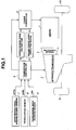
- a power train includes an engine 1 and an automatic transmission 2.
- the engine 1 and the automatic transmission 2 are coupled with each other by way of a connection/disconnection element 3 such as a torque converter and an electromagnetic clutch.
- the automatic transmission 2 employed in this embodiment is a step-type transmission and adapted to select a gear range through a selective hydraulic operation (engagement) of a plurality of frictional elements (wet clutches, wet brakes, etc.) and to be shifted to another gear range by changing the frictional elements (wet clutch, wet brake or the like) that are selected to perform the hydraulic operation.
- the automatic transmission 2 is an automatic transaxle having a built-in differential gear and connected at an output shaft to left and right driving wheels (front wheels) by way of the differential gear.
- the power from the engine 1 is inputted through the connection/disconnection element 3 to the automatic transmission 2, the automatic transmission 2 changes the engine power according to the selected gear range, and the changed engine power is transmitted from the differential gear to the left and right driving wheels (front wheels) 4L and 4R to drive the vehicle.
- the engine 1 has within an intake pipe an electronically controlled throttle valve, the throttle opening degree TVO of which varies basically depending upon a variation of an amount of depression of an accelerator pedal (accelerator opening degree) APO but which is of the type capable of executing a torque down and a torque up of the engine 1 by controlling the throttle opening degree TVO suitably in accordance with an engine output (torque) control demand (torque down control demand for reducing a shift shock), separately from the accelerator opening degree APO.
- the throttle opening degree TVO of which varies basically depending upon a variation of an amount of depression of an accelerator pedal (accelerator opening degree) APO but which is of the type capable of executing a torque down and a torque up of the engine 1 by controlling the throttle opening degree TVO suitably in accordance with an engine output (torque) control demand (torque down control demand for reducing a shift shock), separately from the accelerator opening degree APO.
- the engine 1 is operated by igniting, by a spark from a spark plug, a mixture of an intake air of an amount that is controlled by the throttle valve and a fuel that is supplied by injection of an injector.
- the electronic control of the throttle valve, the control of the amount of fuel supplied by the injector and the control of the ignition timing of the spark plug are executed by the engine controller 5 together with other controls of the engine 1 (e.g., valve lift control of intake and exhaust valves and valve opening and closing timing control for compression ratio control), thereby determining the engine output.
- other controls of the engine 1 e.g., valve lift control of intake and exhaust valves and valve opening and closing timing control for compression ratio control
- the engine torque control for shift shock reduction can be used a single of or any combination of an engine torque control by a throttle opening degree control, an engine torque control by a fuel supply amount control, an engine torque control by an ignition timing control, an engine torque control by an intake/exhaust valve lift control and an engine toque control by a compression ratio control.
- the automatic transmission 2 is controlled by the transmission controller 6, and to the transmission controller 6 are inputted, in addition to an engine torque down execution signal for shift shock reduction from the engine controller 5, a signal from the accelerator opening degree sensor 7 for detecting the accelerator opening degree APO, a signal from the vehicle speed sensor 8 for detecting a vehicle speed VSP and a signal from a transmission input rotation sensor 9 for detecting a transmission input rotation Ni.
- the transmission controller 6 obtains from the above-described information a target gear range on the basis of a predetermined gearshift map and does not execute gearshift when the selected gear range coincides with the target gear range but executes gearshift from the selected gear range to the target gear range when the selected gear range does not coincide with the target gear range.
- the frictional element that is to be engaged for selection of the target gear range is engaged by increasing the working oil pressure supplied thereto and the frictional element that is to be released for selection of the gear range is released by decreasing the working oil pressure supplied thereto, thereby executing gearshift from the selected gear range to the target gear range.
- the transmission controller 6 issues an engine torque down instruction for prevention of shift shock, according to the necessity as shown in FIG. 1, for performing a torque down including the above-described pre-torque down and the engine controller 5 executes a control for realizing the torque down, as an electronic control of the throttle opening degree.
- the transmission controller 6 executes a control program shown in FIG. 2 and thereby performs the working oil pressure control of the frictional elements, which the present invention aims at, as follows.
- step S1 of FIG. 2 it is checked, on the basis of an engine torque down execution signal from the engine controller 5, whether a pre-torque down of the engine is executed at a torque phase before the start of an inertia phase.
- step S2 a rising gradient ⁇ 1 of working oil pressure, which represents a rate of increase of the working oil pressure per unit time, during the torque phase of the engagement side frictional element is determined by using a map for exclusive use, based on the engine torque Te and the vehicle speed VSP.
- the rising gradient ⁇ 1 of the working oil pressure during the torque phase of the engagement side frictional element is determined so as to become larger or steeper as the engine torque Te becomes larger or the vehicle speed VSP becomes higher.
- step S3 by using an exclusive map, a falling gradient ⁇ 1 of the working oil pressure during the torque phase of the engagement side frictional element is determined on the basis of the engine torque Te and the vehicle speed VSP.
- the falling gradient ⁇ 1 of the working oil pressure during the torque phase of the engagement side frictional element is determined so as to become larger or steeper as the engine torque Te becomes larger or the vehicle speed VSP becomes higher.
- step S4 a rising gradient ⁇ 1 of the working oil pressure during the inertia phase of the engagement side frictional element is calculated by multiplying the rising gradient ⁇ 1 during the torque phase of the engagement side frictional element by a predetermined operation coefficient.
- step S1 If it is determined in step S1 that a pre-torque down of the engine is executed during the torque phase, the program goes to step S5 where a rising gradient ⁇ 2 of the working oil pressure during the torque phase of the engagement side frictional element is determined based on the engine torque Te and the vehicle speed VSP by using an exclusive map.
- step S6 a falling gradient ⁇ 2 of the working oil pressure during the torque phase of the release side frictional element is determined based on the engine torque Te and the vehicle speed VSP by using an exclusive map.
- step S7 a rising gradient ⁇ 2 of the working oil pressure during the inertia phase of the engagement side frictional element is calculated by multiplying the rising gradient ⁇ 2 of the working oil pressure Pc during the torque phase of the engagement side frictional element by a predetermined operation coefficient.
- the operation coefficient is determined so that the rising gradient ⁇ 2 of working oil pressure Pc during the inertia phase of the engagement side frictional element is set at ⁇ that is equal to ⁇ 1 obtained through calculation in step S4 when the pre-torque down is not executed.
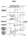
- FIG. 3 is a motion-time chart in case an upshift instruction for shifting from a selected gear range (n range) that is currently selected at the moment t1 to a target gear range (n+1 range) is outputted and a gear shift (upshift) is performed in response to the instruction.
- the upshift is performed by decreasing the working oil pressure Po of the release side frictional element that is to be released at gearshift while increasing the working oil pressure Pc of the engagement side frictional element that is to be engaged at gearshift.
- an engine torque-down amount ⁇ Tedown is determined as shown by the dotted line thereby decreasing the engine torque Te only during the inertia phase in which the effective gear ratio Gr is changing from a value equivalent to a selected gear range (n range) to a value equivalent to a target gear range (n+1 range)
- the working oil pressure Pc supplied to the engagement side frictional element is controlled as shown by the solid line to cause the rising gradient ⁇ 2 of the working oil pressure Pc during the torque phase of the engagement side frictional element to become larger or steeper than the rising gradient ⁇ 1 in case the pretorque down is not executed.
- the rising gradient ⁇ 2 of the working oil pressure during the inertia phase of the engagement side frictional element is set at ⁇ that is equal to the gradient ⁇ 1 in case the pre-torque down is not executed.
- the working oil pressure Pc supplied to the engagement side frictional element during the torque phase in case the pre-torque down is executed is controlled so as to be higher than that in case the pre-torque down is not executed since ⁇ 2 > ⁇ 1, so that in case, for example, the input torque is decreased as shown by the two-dot chain line A, there never occurs such a case in which the transmission output torque is balanced with the transmission input torque when the transmission torque capacity is low, thus causing the transmission output torque To to make a time change as shown by the solid line and thereby making a pull-in torque ⁇ To smaller to enable to wipe off a fear of occurrence of a large shift shock.
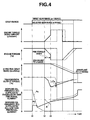
- the falling gradient ⁇ 2 of the working oil pressure Po during the torque phase of the release side frictional element in case the pre-torque down is executed is determined so as to be steeper than the falling gradient ⁇ 1 in case the pre-torque down is not executed, thereby accelerating decrease of the working oil pressure Po of the release side frictional element, the working oil pressure Po discharged from the release side frictional element is controlled so as to be lower during the torque phase in case the pre-torque down is executed than in case the pre-torque down is not executed, the following effect can be obtained.
- the rising gradient of the working oil pressure Pc on the engagement side during the torque phase is maintained constantly at ⁇ 2
- the rising gradient may first be set at ⁇ 1 and then changed to ⁇ 2 at or adjacent the moment t2 and onward, or the rising gradient may first be set at ⁇ 2 and then changed to ⁇ 1 at or adjacent the moment t2 and onward.
Landscapes
- Engineering & Computer Science (AREA)
- General Engineering & Computer Science (AREA)
- Mechanical Engineering (AREA)
- Physics & Mathematics (AREA)
- Fluid Mechanics (AREA)
- Automation & Control Theory (AREA)
- Transportation (AREA)
- Control Of Transmission Device (AREA)
Applications Claiming Priority (2)
| Application Number | Priority Date | Filing Date | Title |
|---|---|---|---|
| JP2006230290 | 2006-08-28 | ||
| JP2007128783A JP4745284B2 (ja) | 2006-08-28 | 2007-05-15 | パワートレーンの変速ショック軽減装置 |
Publications (3)
| Publication Number | Publication Date |
|---|---|
| EP1895202A2 true EP1895202A2 (fr) | 2008-03-05 |
| EP1895202A3 EP1895202A3 (fr) | 2011-05-11 |
| EP1895202B1 EP1895202B1 (fr) | 2012-05-16 |
Family
ID=38775571
Family Applications (1)
| Application Number | Title | Priority Date | Filing Date |
|---|---|---|---|
| EP07015714A Active EP1895202B1 (fr) | 2006-08-28 | 2007-08-09 | Dispositif pour la réduction du choc du changement de vitesse pour un ensemble transmission |
Country Status (5)
| Country | Link |
|---|---|
| US (1) | US7695405B2 (fr) |
| EP (1) | EP1895202B1 (fr) |
| JP (1) | JP4745284B2 (fr) |
| KR (1) | KR100892827B1 (fr) |
| CN (1) | CN101135371B (fr) |
Cited By (2)
| Publication number | Priority date | Publication date | Assignee | Title |
|---|---|---|---|---|
| EP2457794A3 (fr) * | 2010-11-24 | 2014-01-22 | ZF Friedrichshafen AG | Procédé destiné au fonctionnement d'une chaîne cinématique |
| WO2020148361A1 (fr) * | 2019-01-17 | 2020-07-23 | Zf Friedrichshafen Ag | Procédé et unité de commande pour faire fonctionner une boîte de vitesses à changement de rapport en charge |
Families Citing this family (9)
| Publication number | Priority date | Publication date | Assignee | Title |
|---|---|---|---|---|
| JP4360406B2 (ja) * | 2007-01-10 | 2009-11-11 | トヨタ自動車株式会社 | パワートレーンの制御装置、制御方法、その方法を実現させるプログラムおよびそのプログラムを記録した記録媒体 |
| US8214116B2 (en) * | 2007-07-11 | 2012-07-03 | GM Global Technology Operations LLC | Apparatus and method for decreasing an upshift delay in an automatic transmission |
| JP5742124B2 (ja) * | 2010-07-21 | 2015-07-01 | 日産自動車株式会社 | ハイブリッド車両の制御装置 |
| US8504265B2 (en) * | 2011-05-20 | 2013-08-06 | GM Global Technology Operations LLC | System and method for decreasing acceleration disturbance during transmission upshifts |
| US9470309B2 (en) * | 2012-07-31 | 2016-10-18 | Toyota Jidosha Kabushiki Kaisha | Vehicle transmission controller |
| WO2014076822A1 (fr) * | 2012-11-16 | 2014-05-22 | トヨタ自動車株式会社 | Dispositif de commande de transmission de véhicule |
| WO2015060051A1 (fr) * | 2013-10-23 | 2015-04-30 | ジヤトコ株式会社 | Dispositif de commande pour transmission à variation continue |
| KR101812038B1 (ko) | 2015-10-05 | 2017-12-27 | 한국에너지기술연구원 | 셀룰로오스 기반 미세 탄화체, 이의 제조방법 및 셀룰로오스 기반 미세 탄화체를 이용한 촉매지지체의 제조방법 |
| JP7118526B2 (ja) * | 2018-03-16 | 2022-08-16 | ジヤトコ株式会社 | 自動変速機のアップシフト制御装置 |
Citations (1)
| Publication number | Priority date | Publication date | Assignee | Title |
|---|---|---|---|---|
| JPH07139381A (ja) | 1993-11-19 | 1995-05-30 | Nissan Motor Co Ltd | 自動変速機の変速制御装置 |
Family Cites Families (16)
| Publication number | Priority date | Publication date | Assignee | Title |
|---|---|---|---|---|
| JPH0663560B2 (ja) * | 1985-08-21 | 1994-08-22 | 三菱自動車工業株式会社 | 車両用自動変速機 |
| JPH0781627B2 (ja) * | 1988-02-05 | 1995-09-06 | 日産自動車株式会社 | 自動変速機のライン圧制御装置 |
| JP2856255B2 (ja) * | 1989-02-28 | 1999-02-10 | 日産自動車株式会社 | 自動変速機の液圧制御装置 |
| US5188005A (en) * | 1990-09-14 | 1993-02-23 | Ford Motor Company | Method and system for improving smoothness of shifts in an automatic transmission |
| JPH0932912A (ja) * | 1995-07-20 | 1997-02-07 | Toyota Motor Corp | 車両用自動変速機の変速制御装置 |
| JPH09256883A (ja) * | 1996-03-25 | 1997-09-30 | Toyota Motor Corp | エンジンおよび自動変速機の一体制御装置 |
| JP3252731B2 (ja) * | 1996-12-25 | 2002-02-04 | アイシン・エィ・ダブリュ株式会社 | 自動変速機の変速制御装置 |
| JP3562425B2 (ja) * | 2000-03-07 | 2004-09-08 | 日産自動車株式会社 | 自動変速機のアップシフトショック軽減装置 |
| US6332860B1 (en) * | 2000-03-20 | 2001-12-25 | General Motors Corporation | Model-based on-coming clutch pressure control for an automatic transmission upshift |
| JP4097890B2 (ja) * | 2000-09-18 | 2008-06-11 | ジヤトコ株式会社 | 自動変速機の変速制御装置 |
| EP1319873A4 (fr) * | 2000-09-18 | 2009-03-11 | Jatco Ltd | Appareil de commande des vitesses d'une transmission automatique |
| JP4002737B2 (ja) * | 2001-04-11 | 2007-11-07 | ジヤトコ株式会社 | 自動変速機の変速制御装置 |
| EP1431624B1 (fr) * | 2001-09-28 | 2009-11-11 | JATCO Ltd | Dispositif de commande de changement de vitesses pour transmission automatique |
| JP2004291908A (ja) * | 2003-03-28 | 2004-10-21 | Toyota Motor Corp | 自動変速機の制御装置および制御方法 |
| JP4158586B2 (ja) * | 2003-04-17 | 2008-10-01 | 日産自動車株式会社 | 自動変速機の変速制御装置 |
| US7351183B2 (en) * | 2004-12-16 | 2008-04-01 | Ford Global Technologies, Llc | Ratio shift control for a multiple ratio automatic transmission |
-
2007
- 2007-05-15 JP JP2007128783A patent/JP4745284B2/ja active Active
- 2007-08-08 US US11/882,992 patent/US7695405B2/en active Active
- 2007-08-09 EP EP07015714A patent/EP1895202B1/fr active Active
- 2007-08-22 KR KR1020070084303A patent/KR100892827B1/ko active IP Right Grant
- 2007-08-28 CN CN2007101482177A patent/CN101135371B/zh active Active
Patent Citations (1)
| Publication number | Priority date | Publication date | Assignee | Title |
|---|---|---|---|---|
| JPH07139381A (ja) | 1993-11-19 | 1995-05-30 | Nissan Motor Co Ltd | 自動変速機の変速制御装置 |
Cited By (6)
| Publication number | Priority date | Publication date | Assignee | Title |
|---|---|---|---|---|
| EP2457794A3 (fr) * | 2010-11-24 | 2014-01-22 | ZF Friedrichshafen AG | Procédé destiné au fonctionnement d'une chaîne cinématique |
| WO2020148361A1 (fr) * | 2019-01-17 | 2020-07-23 | Zf Friedrichshafen Ag | Procédé et unité de commande pour faire fonctionner une boîte de vitesses à changement de rapport en charge |
| CN113348315A (zh) * | 2019-01-17 | 2021-09-03 | 采埃孚股份公司 | 用于操作可动力换挡的变速器的方法和控制单元 |
| KR20210113993A (ko) * | 2019-01-17 | 2021-09-17 | 젯트에프 프리드리히스하펜 아게 | 파워 시프트 트랜스미션을 작동하기 위한 방법 및 제어 유닛 |
| CN113348315B (zh) * | 2019-01-17 | 2023-01-03 | 采埃孚股份公司 | 用于操作可动力换挡的变速器的方法和控制单元 |
| US11635136B2 (en) | 2019-01-17 | 2023-04-25 | Zf Friedrichshafen Ag | Method and control unit for operating a power-shift transmission |
Also Published As
| Publication number | Publication date |
|---|---|
| US20080051254A1 (en) | 2008-02-28 |
| CN101135371A (zh) | 2008-03-05 |
| EP1895202B1 (fr) | 2012-05-16 |
| JP4745284B2 (ja) | 2011-08-10 |
| US7695405B2 (en) | 2010-04-13 |
| EP1895202A3 (fr) | 2011-05-11 |
| KR20080019546A (ko) | 2008-03-04 |
| JP2008082535A (ja) | 2008-04-10 |
| KR100892827B1 (ko) | 2009-04-10 |
| CN101135371B (zh) | 2010-04-21 |
Similar Documents
| Publication | Publication Date | Title |
|---|---|---|
| EP1895202B1 (fr) | Dispositif pour la réduction du choc du changement de vitesse pour un ensemble transmission | |
| JP4155287B2 (ja) | 車両用自動変速機の変速制御装置 | |
| US7549946B2 (en) | Shift control apparatus and shift control method of automatic transmission of vehicle | |
| US7740559B2 (en) | Shift control device of vehicular automatic transmission | |
| JP2007327574A (ja) | パワートレーンの変速ショック軽減装置 | |
| JP4534255B2 (ja) | 自動変速機の制御装置 | |
| US7563198B2 (en) | Shift control device and shift control method of automatic transmission | |
| JP4639760B2 (ja) | 自動変速機の変速制御装置 | |
| JP4743289B2 (ja) | 車両用駆動装置の制御装置 | |
| WO2005075239A1 (fr) | Dispositif de commande du moteur d’une boite de vitesse pour un véhicule | |
| US6889130B2 (en) | Shift control system for automatic transmission | |
| JP2004218799A (ja) | 車両用高加速時変速制御装置 | |
| JP4682122B2 (ja) | 自動変速機の制御装置 | |
| JP2004116479A (ja) | 車両用自動変速機の変速時遅角制御装置 | |
| WO2017033900A1 (fr) | Dispositif de commande pour boîte de vitesses automatique | |
| JP2008240561A (ja) | 車両の制御装置、制御方法、その方法を実現させるプログラムおよびそのプログラムを記録した記録媒体 | |
| JP2004108168A (ja) | ダウンシフト時のトルクダウン制御装置 | |
| JP2009103065A (ja) | 車両の出力制御装置 | |
| JP2000008901A (ja) | 原動機と自動変速機との一体制御装置 | |
| JP2008014254A (ja) | 自動変速機の制御装置 | |
| JP4924060B2 (ja) | 自動変速機の制御装置 | |
| JP2010007767A (ja) | 自動変速機の制御装置 | |
| JP2011247227A (ja) | 車両の制御装置 | |
| JP5451437B2 (ja) | 自動変速機の制御装置 | |
| JP2008164121A (ja) | 自動変速機の変速制御装置 |
Legal Events
| Date | Code | Title | Description |
|---|---|---|---|
| PUAI | Public reference made under article 153(3) epc to a published international application that has entered the european phase |
Free format text: ORIGINAL CODE: 0009012 |
|
| 17P | Request for examination filed |
Effective date: 20070809 |
|
| AK | Designated contracting states |
Kind code of ref document: A2 Designated state(s): AT BE BG CH CY CZ DE DK EE ES FI FR GB GR HU IE IS IT LI LT LU LV MC MT NL PL PT RO SE SI SK TR |
|
| AX | Request for extension of the european patent |
Extension state: AL BA HR MK YU |
|
| PUAL | Search report despatched |
Free format text: ORIGINAL CODE: 0009013 |
|
| AK | Designated contracting states |
Kind code of ref document: A3 Designated state(s): AT BE BG CH CY CZ DE DK EE ES FI FR GB GR HU IE IS IT LI LT LU LV MC MT NL PL PT RO SE SI SK TR |
|
| AX | Request for extension of the european patent |
Extension state: AL BA HR MK RS |
|
| GRAP | Despatch of communication of intention to grant a patent |
Free format text: ORIGINAL CODE: EPIDOSNIGR1 |
|
| RIC1 | Information provided on ipc code assigned before grant |
Ipc: F16H 61/06 20060101AFI20110704BHEP Ipc: B60W 30/18 20060101ALI20110704BHEP Ipc: B60W 10/10 20060101ALN20110704BHEP Ipc: B60W 10/06 20060101ALN20110704BHEP Ipc: F16H 63/50 20060101ALI20110704BHEP |
|
| GRAS | Grant fee paid |
Free format text: ORIGINAL CODE: EPIDOSNIGR3 |
|
| RAP1 | Party data changed (applicant data changed or rights of an application transferred) |
Owner name: NISSAN MOTOR CO., LTD. Owner name: JATCO LTD |
|
| AKX | Designation fees paid |
Designated state(s): DE FR GB IT |
|
| GRAA | (expected) grant |
Free format text: ORIGINAL CODE: 0009210 |
|
| RAP1 | Party data changed (applicant data changed or rights of an application transferred) |
Owner name: JATCO LTD Owner name: NISSAN MOTOR CO., LTD. |
|
| AK | Designated contracting states |
Kind code of ref document: B1 Designated state(s): DE FR GB IT |
|
| REG | Reference to a national code |
Ref country code: GB Ref legal event code: FG4D |
|
| REG | Reference to a national code |
Ref country code: DE Ref legal event code: R096 Ref document number: 602007022570 Country of ref document: DE Effective date: 20120719 |
|
| PLBE | No opposition filed within time limit |
Free format text: ORIGINAL CODE: 0009261 |
|
| STAA | Information on the status of an ep patent application or granted ep patent |
Free format text: STATUS: NO OPPOSITION FILED WITHIN TIME LIMIT |
|
| 26N | No opposition filed |
Effective date: 20130219 |
|
| REG | Reference to a national code |
Ref country code: DE Ref legal event code: R097 Ref document number: 602007022570 Country of ref document: DE Effective date: 20130219 |
|
| REG | Reference to a national code |
Ref country code: FR Ref legal event code: PLFP Year of fee payment: 10 |
|
| REG | Reference to a national code |
Ref country code: FR Ref legal event code: PLFP Year of fee payment: 11 |
|
| REG | Reference to a national code |
Ref country code: FR Ref legal event code: PLFP Year of fee payment: 12 |
|
| REG | Reference to a national code |
Ref country code: DE Ref legal event code: R082 Ref document number: 602007022570 Country of ref document: DE Representative=s name: GRUENECKER PATENT- UND RECHTSANWAELTE PARTG MB, DE Ref country code: DE Ref legal event code: R081 Ref document number: 602007022570 Country of ref document: DE Owner name: NISSAN MOTOR CO., LTD., YOKOHAMA-SHI, JP Free format text: FORMER OWNERS: JATCO LTD, FUJI, SHIZUOKA, JP; NISSAN MOTOR CO., LTD., YOKOHAMA-SHI, KANAGAWA-KEN, JP |
|
| REG | Reference to a national code |
Ref country code: GB Ref legal event code: 732E Free format text: REGISTERED BETWEEN 20200305 AND 20200311 |
|
| PG25 | Lapsed in a contracting state [announced via postgrant information from national office to epo] |
Ref country code: IT Free format text: LAPSE BECAUSE OF NON-PAYMENT OF DUE FEES Effective date: 20190809 |
|
| PGFP | Annual fee paid to national office [announced via postgrant information from national office to epo] |
Ref country code: GB Payment date: 20230720 Year of fee payment: 17 |
|
| PGFP | Annual fee paid to national office [announced via postgrant information from national office to epo] |
Ref country code: FR Payment date: 20230720 Year of fee payment: 17 |
|
| PGFP | Annual fee paid to national office [announced via postgrant information from national office to epo] |
Ref country code: DE Payment date: 20240723 Year of fee payment: 18 |