EP1894875B1 - Dispositif de sécurité pour installation d'élévation et installation d'élévation dotée d'un tel dispositif de sécurité - Google Patents
Dispositif de sécurité pour installation d'élévation et installation d'élévation dotée d'un tel dispositif de sécurité Download PDFInfo
- Publication number
- EP1894875B1 EP1894875B1 EP20070115231 EP07115231A EP1894875B1 EP 1894875 B1 EP1894875 B1 EP 1894875B1 EP 20070115231 EP20070115231 EP 20070115231 EP 07115231 A EP07115231 A EP 07115231A EP 1894875 B1 EP1894875 B1 EP 1894875B1
- Authority
- EP
- European Patent Office
- Prior art keywords
- lift
- detector
- safety equipment
- region
- lift cage
- Prior art date
- Legal status (The legal status is an assumption and is not a legal conclusion. Google has not performed a legal analysis and makes no representation as to the accuracy of the status listed.)
- Not-in-force
Links
Images


Classifications
-
- B—PERFORMING OPERATIONS; TRANSPORTING
- B66—HOISTING; LIFTING; HAULING
- B66B—ELEVATORS; ESCALATORS OR MOVING WALKWAYS
- B66B1/00—Control systems of elevators in general
- B66B1/34—Details, e.g. call counting devices, data transmission from car to control system, devices giving information to the control system
- B66B1/3492—Position or motion detectors or driving means for the detector
-
- B—PERFORMING OPERATIONS; TRANSPORTING
- B66—HOISTING; LIFTING; HAULING
- B66B—ELEVATORS; ESCALATORS OR MOVING WALKWAYS
- B66B5/00—Applications of checking, fault-correcting, or safety devices in elevators
- B66B5/0006—Monitoring devices or performance analysers
- B66B5/0018—Devices monitoring the operating condition of the elevator system
- B66B5/0031—Devices monitoring the operating condition of the elevator system for safety reasons
Definitions
- the invention relates to a safety device for an elevator installation with at least one elevator car according to the preamble of the independent claims.
- the invention relates to a corresponding elevator installation.
- elevator cars in a multi-vehicle elevator system are each equipped with their own drive and their own braking system.
- the electronic control of the entire elevator system is often designed so that there should be no collisions of the individual elevator cars. Particularly in the case of an emergency stop or even in the case of a normal floor stop of a cabin, it can not be ensured under all circumstances that a further elevator car situated above or below the same elevator shaft can still stop in time to avoid a collision. This could be avoided by giving the controller sufficient distances between the individual elevator cars and also adapted vertical speeds. Such a requirement, however, can not fully utilize the transport capacity of a multi-vehicle elevator installation, which has an impact on the cost-benefit efficiency.
- a multi-mobile elevator system which includes means for opening the safety circuit of an elevator car, if it comes to an undesired approach to another elevator car.
- security modules are present at each elevator car, which evaluate the car positions and speeds in order to be able to trigger braking operations on other elevator cars, if necessary.
- the individual safety modules must always know and evaluate the cabin positions and speeds of the other elevator cars involved in order to be able to react correctly in an emergency. To it needs a special decision module, which is responsible for determining the stop commands in an emergency.
- a first object of the present invention to provide a multi-vehicle elevator system, which are automatically stopped at an approach between two elevator cars, the cabs before driving without a complex exchange of information between the elevator cars is necessary.
- a further object of the present invention is to prevent an undesired approach or collision of the car with the shaft ends in an elevator installation with at least one elevator car when the elevator car approaches the shaft ends.
- the present invention is equally suitable for preventing a collision between two elevator cars that are relatively approaching and one for preventing a collision between an elevator car and a shaft end.
- equivalent variants of the safety device according to the invention for an elevator installation will be described.
- the safety device for an elevator installation with an upper elevator car and a lower elevator car both of which can be moved substantially independently along a vertical direction in a common elevator shaft of the elevator installation, comprises a first electro-optical detection system with a first light source in a lower area the upper elevator car and with a first detector.
- the first detector has a photosensitive, first sensor area in an upper area of the lower elevator car.
- the first light source outputs a collimated first light beam at a first angle with respect to the vertical direction. The first angle is predetermined so that when approaching the upper and lower elevator cars, the first light beam strikes the first sensor area and is thus detectable by the first detector and the first detector triggers a reaction to prevent a collision of the elevator cars.
- the safety device has a second electro-optical detection system with a second light source in an upper region of the lower elevator car and a second detector in a lower region of the upper elevator car comprises.
- the first variant can also be implemented with more than two elevator cars, which can be moved substantially independently vertically in a common elevator shaft. Where then between each of these elevator cars at least one light source and provided for this detector is present.
- the safety device for an elevator installation with a lower shaft end and with at least one elevator car which is movable substantially independently along a vertical direction in an elevator shaft of the elevator installation, comprises a first electro-optical detection system with a first light source in a lower area of the elevator system Elevator car and with a first detector.
- the first detector has a photosensitive, first sensor area in the region of the lower shaft end.
- the first light source outputs a collimated first light beam at a first angle with respect to the vertical direction. The first angle is predetermined such that when the elevator car approaches the lower shaft end, the first light beam strikes the first sensor area and is thus detectable by the first detector and the first detector triggers a reaction to prevent a collision of the elevator car.
- the safety device has a second electro-optical detection system with a second light source in the region of the lower shaft end and via a second detector in a lower region of the elevator car.
- the safety device for an elevator installation with an upper shaft end and with at least one elevator car which is movable substantially independently along a vertical direction in an elevator shaft of the elevator installation, comprises a first electro-optical detection system with a first light source in the region of the upper shaft end and with a first detector.
- the first detector has a photosensitive, first sensor area in the upper area of the elevator car.
- the first light source outputs a collimated first light beam at a first angle with respect to the vertical direction. The first angle is predetermined such that, when the elevator car approaches the upper shaft end, the first light beam strikes the first sensor area and is thus detectable by the first detector and the first detector triggers a reaction to prevent a collision of the elevator car.
- the safety device has a second electro-optical detection system with a second light source in an upper region of the elevator car and a second detector in the region of the upper shaft end.
- the elevator car of the second variant may be the lower of several elevator cars in a common elevator shaft of the elevator system of the first variant, both of which are substantially independently movable along a vertical direction in the elevator shaft.
- the elevator car of the third variant can be the upper one of a plurality of elevator cars in a common elevator shaft of the elevator system of the first variant, both of which can be moved substantially independently along a vertical direction in the elevator shaft.
- An advantage of the invention results from the simple arrangement of commercially available electro-optical components in order to prevent a collision of an elevator car in an elevator shaft. Another advantage is thesurgiigen detection of the distance by the detector and the triggering of an autonomous reaction to unwanted approach of the elevator cars. Furthermore, the detector in conjunction with a local computing unit is capable of triggering a collision-preventing reaction based on speed information with a small amount of computation. In addition, the redundant design of the safety device provides additional security and enables an autonomous and rapid collision-preventing reaction of all elevator cars.
- a first embodiment of the invention is in connection with the two snapshots in the Figures 1A and 1B described. Shown is a simple multi-vehicle elevator installation 10 with an upper elevator car A1 and a lower elevator car A2, both of which can be moved substantially independently vertically in a common elevator shaft 11 of the elevator installation 10 along a vertical direction z.
- the elevator cabs A1, A2 are provided with a drive and a holding brake per elevator car A1, A2, or, for example, can be individually coupled to a central drive system in order to allow individual movement in the elevator shaft 11.
- a safety device which comprises a first electro-optical detection system 20 having a first light source 21 arranged in a lower area of the upper elevator car A1, as in FIGS Figures 1A and 1B indicated schematically.
- Particularly suitable light sources are light-emitting diodes which emit concentrated light. Even better are laser diode or solid state laser.
- the detection system 20 comprises a first detector 22, which comprises a photosensitive, first sensor area 22 in an upper area of the lower elevator car A2.
- a first detector 22 which comprises a photosensitive, first sensor area 22 in an upper area of the lower elevator car A2.
- sensor region 22 photodiodes, phototransistors or other photosensitive elements can be used.
- the first light source 21 is designed and arranged to emit a collimated first light beam L1 at a first angle W1 with respect to the vertical direction z in.
- the light beam L1 is directed downwards.
- the first angle W1 is predetermined or adjusted such that, as the upper and lower elevator cars A1, A2 approach, the first light beam L1 strikes the first sensor region 22 as soon as the minimum distance S2 is reached. At this instant of impact, the light beam L1 is thus detectable by the first detector 22, 24, and this detector 22, 24 triggers a reaction R1, which is passed on to a controller or the like, for example via a line or connection 23.
- the present invention now permits various forms of implementation or expansion stages of the safety device.
- a reaction can be triggered immediately upon first contact of the light beam L1 with the sensor region 22.
- the sensor region 22 has a size-in the sense of surface area-that makes it possible to ensure that reliable detection of the light beam L1 by the detector 22, 24 is possible despite the fluctuations in the elevator installation 10 ,
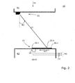
- FIG. 2 Another embodiment of the invention is shown in Fig. 2 indicated.
- a snapshot is shown shortly after the light beam L1 was first detected by a photosensitive portion 22.1 of the sensor portion 22.
- the sections are preferably separately evaluable, ie they each have individual electrical connections.
- a corresponding evaluation system 24 (or 24 and 28 in the case of Fig. 3 ) is provided to trigger an adapted response (R1, R2, R3, R4) in response to which of the sections 22.1 - 22.n the first light beam L1 strikes.
- the safety device can now be configured, programmed or set such that upon the first impact on the section 22.1 of the sensor region 22 an advance warning is issued as a reaction or the elevator installation 10 or the elevator car A1 and / or A2 is transferred to a pre-warning mode. If the light point now exceeds a predetermined further section 22.4 of the sensor region 22, a final reaction can be triggered (for example an emergency stop by triggering the brake device or the safety brake of the upper and / or the lower elevator car A1, A2). This two-step approach adds security and helps prevent false tripping.
- Fig. 3 another variant is shown. This variant is currently preferred because it offers the greatest security.
- the first detection system is designed analogously to the system shown in the preceding figures.
- the second Detection system can be identical, but sits almost mirrored in the upper part of the lower elevator car A2.
- the corresponding second sensor area 26 is seated in the lower area of the upper elevator car A1.
- the detectors trigger reactions in each case.
- the nature of the reactions differs depending on the embodiment, programming or setting of the devices.
- the detectors are capable of delivering signals or information via lines or other connections 23 or 27. These signals or information are then either processed before reactions are triggered, or they immediately trigger the responses, for example, by opening a switch that is part of a safety circuit.
- the elevator installation 10 has its own safety circuit per elevator car A1, A2, the safety circuit of the upper and / or lower elevator car A1, A2 can be interrupted by the detector (s).
- a multi-mobile elevator installation 10 preferably has one own safety circuit per elevator car A1, A2, in which several safety elements, such as safety contacts and switches, are arranged in a series connection.
- the corresponding elevator car A1 or A2 can only be moved if the safety circuit and thus also all safety contacts integrated in it are closed.
- the safety circuit is connected to the drive or the brake unit of the elevator installation 10 in order to interrupt the driving operation of the corresponding elevator car A1 or A2, if such a reaction is desired.
- the invention can also be used in elevator systems which are equipped with a safety bus system instead of the mentioned safety circuit.
- any catch brakes of the respective elevator cars A1, A2 can be triggered.
- angles W1, W2 can be adjusted in a range of 0 to 90 ° with respect to the vertical direction z.
- the angles W1, W2 are in the range between 0 and 60 degrees, and more preferably between 10 and 50 degrees.
- the angle W1, W2 as a function of individual or several parameters, such as the position, speed or acceleration of an elevator car A1, A2, the distance, relative speed or relative acceleration of the elevator car A1, A2 to a reference point or the operating state of the elevator system 10, in time set variably.
- the angle W1, W2 can be set smaller, so that the light beam L1, L2 falls on the detector 22, 24 at an earlier time and thus to it an earlier time a reaction R1, R2, R3, R4 can trigger.
- the need for an early response R1, R2, R3, R4 is reduced, and thus a larger angle W1, W2 can be set.
- the relationship between acceleration and angle is analogous.
- the angle W1, W2 of the light beam L1, L2 can be increased already after the transfer of the elevator car A1, A2 into an inspection state, since the elevator car A1, A2 can only be moved at reduced speed.
- the position of the elevator cars A1, A2 serves, for example, to determine the time of a variable adjustment of the angle W1, W2. Accordingly, a critical distance between the elevator cars A1, A2 or between an elevator car A1, A2 and the shaft end defined. If this value is undershot, the variable setting of the angle W1, W2 begins.
- corresponding sensor areas can also be provided at the lower and / or upper shaft end of the elevator shaft 11 in order to prevent a dangerous approach of an elevator car to the respective shaft end.
- the operating principle in this case is the same as described in connection with the other embodiments.
Landscapes
- Engineering & Computer Science (AREA)
- Automation & Control Theory (AREA)
- Computer Networks & Wireless Communication (AREA)
- Elevator Control (AREA)
Claims (15)
- Dispositif de sécurité destiné à une installation d'ascenseur (10) avec une cabine d'ascenseur supérieure (A1) et une cabine d'ascenseur inférieure (A2), lesquelles sont susceptibles d'être déplacées essentiellement de façon indépendante le long d'une direction verticale (z) dans une cage d'ascenseur commune (11) de l'installation d'ascenseur (10), auquel cas le dispositif de sécurité comporte un premier système de détection électro-optique (20) avec une première source lumineuse (21) dans un secteur inférieur de la cabine d'ascenseur supérieure (A1) et avec un premier capteur (22, 24),
caractérisé en ce que- le premier capteur (22, 24) comporte un premier secteur de détection photosensible (22) dans un premier secteur supérieur de la cabine d'ascenseur inférieure (A2), et- la première source lumineuse (21) émet un premier rayon lumineux en faisceau (L1) dans un premier angle (W1) par rapport à la direction verticale (z) et le premier angle (W1) est prédéfini de telle sorte que, lors d'un rapprochement des cabines d'ascenseur supérieure et inférieure (A1, A2), le premier rayon lumineux (L1) rencontre le premier secteur de détection (22) et est ainsi susceptible d'être détecté par le premier capteur (22, 24) et le premier capteur (22, 24) déclanche une réaction (R1, R2, R3, R4). - Dispositif de sécurité (20) selon la revendication 1, caractérisé en ce que le dispositif de sécurité (20) comporte un second système de détection électro-optique avec une seconde source lumineuse (25) dans le secteur supérieur de la cabine d'ascenseur inférieure (A2) et avec un second capteur (26, 28) dans un secteur inférieur de la cabine d'ascenseur supérieure (A1).
- Dispositif de sécurité pour une installation d'ascenseur (10) avec une extrémité de cage inférieure et avec au moins une cabine d'ascenseur (A2), laquelle est mobile essentiellement de manière indépendante le long d'une direction verticale (z) dans une cage d'ascenseur (11) de l'installation d'ascenseur (10), auquel cas le dispositif de sécurité comporte un premier système de détection électro-optique (20) avec une première source lumineuse (21) dans un secteur inférieur de la cabine d'ascenseur (A2) et avec un premier capteur (22, 24), caractérisé en ce que- le premier capteur (22, 24) comporte un premier secteur de détection photosensible (22) dans le secteur de l'extrémité de cage inférieure, et- la première source lumineuse (21) émet un premier rayon lumineux en faisceau (L1) dans un premier angle (W1) par rapport à la direction verticale (z) et le premier angle (W1) est fixé de telle sorte que, lors d'un rapprochement de la cabine d'ascenseur (A2) avec la première extrémité de cage inférieure, le premier rayon lumineux (L1) rencontre le premier secteur de détection (22) et est ainsi susceptible d'être détecté par le premier capteur (22, 24) et le premier capteur (22, 24) déclanche une réaction (R1, R2, R3, R4).
- Dispositif de sécurité (20) selon la revendication 3, caractérisé en ce que le dispositif de sécurité (20) comporte un second système de détection électro-optique avec une seconde source lumineuse (25) dans le secteur de l'extrémité de cage inférieure et avec un second capteur (26, 28) dans un secteur inférieur de la cabine d'ascenseur (A2).
- Dispositif de sécurité pour une installation d'ascenseur (10) avec une extrémité de cage supérieure et avec au moins une cabine d'ascenseur (A1), laquelle est mobile essentiellement de manière indépendante le long d'une direction verticale (z) dans une cage d'ascenseur (11) de l'installation d'ascenseur (10), auquel cas le dispositif de sécurité comporte un premier système de détection électro-optique (20) avec une première source lumineuse (21) dans le secteur de l'extrémité de cage supérieure et avec un premier capteur (22, 24), caractérisé en ce que- le premier capteur (22, 24) comporte un premier secteur de détection photosensible (22) dans le secteur supérieur de la cabine d'ascenseur (A1), et- la première source lumineuse (21) émet un premier rayon lumineux en faisceau (L1) dans un premier angle (W1) par rapport à la direction verticale (z) et le premier angle (W1) est fixé de telle sorte que lors d'un rapprochement de la cabine d'ascenseur (A1, A2) avec l'extrémité de cage supérieure, le premier rayon lumineux (L1) rencontre le premier secteur de détection (22) et est ainsi susceptible d'être détecté par le premier capteur (22, 24) et le premier capteur (22, 24) déclanche une réaction (R1, R2, R3, R4).
- Dispositif de sécurité (20) selon la revendication 5, caractérisé en ce que le dispositif de sécurité (20) comporte un second système de détection électro-optique avec une seconde source lumineuse (25) dans un secteur supérieur de la cabine d'ascenseur (A1) et avec un second capteur (26, 28) dans le secteur de l'extrémité de cage supérieure.
- Dispositif de sécurité (20) selon la revendication 3 ou 4, caractérisé en ce que la cabine d'ascenseur (A2) est l'entité inférieure parmi plusieurs cabines d'ascenseur (A1, A2) dans une cage d'ascenseur (11) commune de l'installation d'ascenseur (10), les deux étant mobiles essentiellement de manière indépendante le long d'une direction verticale (z) dans la cage d'ascenseur (11).
- Dispositif de sécurité (20) selon la revendication 5 ou 6, caractérisé en ce que la cabine d'ascenseur (A1) est l'entité supérieure parmi plusieurs cabines d'ascenseur (A1, A2) dans une cage d'ascenseur (11) commune de l'installation d'ascenseur (10), les deux étant mobiles essentiellement de manière indépendante le long d'une direction verticale (z) dans la cage d'ascenseur (11).
- Dispositif de sécurité selon une des revendications précédentes, caractérisé en ce que le premier secteur de détection (22) présente plusieurs sections photosensibles (22.1 - 22.n), lesquelles sont exploitables de manière séparées.
- Dispositif de sécurité selon une des revendications précédentes, caractérisé en ce que le premier capteur (22, 24) comporte un système d'exploitation (24) dans le but de pouvoir déclancher une réaction appropriée (R1, R2, R3, R4) concernant quelle section parmi les sections (22.1 -22.n) rencontre le premier rayon lumineux (L1).
- Dispositif de sécurité selon une des revendications précédentes, caractérisé en ce qu'une ou plusieurs des réactions suivantes est/sont susceptibles d'être déclanchées par le premier capteur (22, 24):- ouverture d'un circuit de sécurité d'au moins une cabine d'ascenseur (A1, A2),- signal à une commande d'ascenseur,- déclanchement d'un dispositif de freinage de au moins une cabine d'ascenseur (A1, A2),- déclanchement d'un frein parachute d'au moins une cabine d'ascenseur (A1, A2),- transfert d'au moins une cabine d'ascenseur (A1, A2) dans un état de pré-alerte,- ajustement de la vitesse verticale (v1, v2) d'au moins une cabine d'ascenseur (A1, A2).
- Dispositif de sécurité selon une des revendications précédentes, caractérisé en ce qu'à l'aide du /des système(s) de détection électro-optique(s) l'on réalise un contrôle de la distance ou un contrôle combiné de la distance et de la vitesse.
- Dispositif de sécurité selon une des revendications précédentes, caractérisé en ce que l'angle (W1, W2) entre le rayon lumineux (L1, L2) et la direction verticale z est susceptible d'être réglée variable dans le temps en fonction de un seul ou plusieurs paramètres.
- Dispositif de sécurité selon la revendication 13, caractérisé en ce que les paramètres, la position, la vitesse ou l'accélération d'une cabine d'ascenseur (A1 , A2) représente la distance, la vitesse relative ou l'accélération relative d'une cabine d'ascenseur (A1 , A2) par rapport à un point de référence ou l'état de fonctionnement de l'installation d'ascenseur (10).
- Installation d'ascenseur (10) avec un dispositif de sécurité (20) selon une des revendications précédentes, auquel cas l'installation d'ascenseur (10) présente au moins une cabine d'ascenseur (A1, A2), avec un entraînement et un frein d'arrêt par cabine d'ascenseur (A1, A2) et auquel cas une collision de la cabine d'ascenseur (A1, A2) est susceptible d'être évitée par la réaction (R1, R2, R3, R4).
Priority Applications (1)
| Application Number | Priority Date | Filing Date | Title |
|---|---|---|---|
| EP20070115231 EP1894875B1 (fr) | 2006-08-31 | 2007-08-29 | Dispositif de sécurité pour installation d'élévation et installation d'élévation dotée d'un tel dispositif de sécurité |
Applications Claiming Priority (2)
| Application Number | Priority Date | Filing Date | Title |
|---|---|---|---|
| EP06119935A EP1894874A1 (fr) | 2006-08-31 | 2006-08-31 | Dispositif de sécurité pour ascenseur |
| EP20070115231 EP1894875B1 (fr) | 2006-08-31 | 2007-08-29 | Dispositif de sécurité pour installation d'élévation et installation d'élévation dotée d'un tel dispositif de sécurité |
Publications (2)
| Publication Number | Publication Date |
|---|---|
| EP1894875A1 EP1894875A1 (fr) | 2008-03-05 |
| EP1894875B1 true EP1894875B1 (fr) | 2009-08-26 |
Family
ID=38996325
Family Applications (1)
| Application Number | Title | Priority Date | Filing Date |
|---|---|---|---|
| EP20070115231 Not-in-force EP1894875B1 (fr) | 2006-08-31 | 2007-08-29 | Dispositif de sécurité pour installation d'élévation et installation d'élévation dotée d'un tel dispositif de sécurité |
Country Status (1)
| Country | Link |
|---|---|
| EP (1) | EP1894875B1 (fr) |
Families Citing this family (1)
| Publication number | Priority date | Publication date | Assignee | Title |
|---|---|---|---|---|
| CN106629315A (zh) * | 2017-02-27 | 2017-05-10 | 中建三局集团有限公司 | 施工升降机梯笼智能防碰撞缓冲系统及实施方法 |
Family Cites Families (4)
| Publication number | Priority date | Publication date | Assignee | Title |
|---|---|---|---|---|
| GB2211046A (en) * | 1987-10-10 | 1989-06-21 | Thames Valley Lift Company Lim | Lift movement monitoring |
| ATE256625T1 (de) * | 1995-10-17 | 2004-01-15 | Inventio Ag | Sicherheitseinrichtung bei multimobil- aufzugsgruppen |
| US6079521A (en) * | 1998-11-24 | 2000-06-27 | Otis Elevator Company | Measuring elevator position with scanning laser beam |
| US6554107B2 (en) * | 2001-09-27 | 2003-04-29 | Mitsubishi Denki Kabushiki Kaisha | Elevator system |
-
2007
- 2007-08-29 EP EP20070115231 patent/EP1894875B1/fr not_active Not-in-force
Also Published As
| Publication number | Publication date |
|---|---|
| EP1894875A1 (fr) | 2008-03-05 |
Similar Documents
| Publication | Publication Date | Title |
|---|---|---|
| EP1894874A1 (fr) | Dispositif de sécurité pour ascenseur | |
| EP1089030B1 (fr) | Procédé et dispositif de contrôle d'une zone de protection | |
| EP1404603B1 (fr) | Installation d'ascenseur avec zone de protection virtuelle au niveau du fond et/ou du sommet de la cage d'ascenseur, et procede de commande de cette installation | |
| EP1698580B1 (fr) | Système s'ascenseur | |
| EP2250115B1 (fr) | Escalier roulant ou trottoir roulant | |
| EP1679279B2 (fr) | Ascenseur avec système de contrôle | |
| EP1362000B1 (fr) | Systeme de securite pour elements mobiles, notamment pour ascenseurs | |
| EP2367746B1 (fr) | Installation d'ascenseur | |
| EP1662349B1 (fr) | Protection de machines dépendant des conditions des machines | |
| WO2009018886A1 (fr) | Système d'ascenseur | |
| EP2585395B1 (fr) | Installation d'élévateur | |
| DE112013007449T5 (de) | Aufzugvorrichtung | |
| EP2306063B2 (fr) | Capteur de sécurité | |
| EP3347295B1 (fr) | Installation de transport de passagers ayant un dispositif destiné a determiner l'état de fonctionnement | |
| EP1905717A1 (fr) | Procédé de fonctionnement d'une installation d'ascenseur, installation d'ascenseur pouvant fonctionner à l'aide de ce dispositif et dispositif de sécurité pour cette installation d'ascenseur | |
| DE3837054C2 (de) | Gefahrenmeldeanlage für ein Fahrzeug insbesondere ein Flurförderzeug | |
| DE60038579T2 (de) | Sicherheitsvorrichtung, um auf einer Aufzugskabine zu arbeiten | |
| WO1991017020A1 (fr) | Dispositif de transport | |
| EP2252537B1 (fr) | Dispositif de mesure pour un système d'ascenseur, et système d'ascenseur pourvu d'un tel dispositif de mesure | |
| EP0280137B1 (fr) | Dispositif de sécurité pour une installation utilisant des véhicules sans chauffeur | |
| EP1894875B1 (fr) | Dispositif de sécurité pour installation d'élévation et installation d'élévation dotée d'un tel dispositif de sécurité | |
| DE102006019595B3 (de) | Gefahrenbereichsabsicherung an einem Rollenwechsler mit einer Trittmatte | |
| DE10104837A1 (de) | Überwachungssystem zur Abfertigungskontrolle eines Zuges, insbes. bei einer U- oder S-Bahn, mit ergänzbarer Überwachung des Gleisbettraumes und Verwendung | |
| WO2022063656A1 (fr) | Dispositif de commande pour un système d'ascenseur | |
| EP2463223B1 (fr) | Dispositif de contrôle de la position d'arrêt d'une cabine d'ascenseur |
Legal Events
| Date | Code | Title | Description |
|---|---|---|---|
| PUAI | Public reference made under article 153(3) epc to a published international application that has entered the european phase |
Free format text: ORIGINAL CODE: 0009012 |
|
| AK | Designated contracting states |
Kind code of ref document: A1 Designated state(s): AT BE BG CH CY CZ DE DK EE ES FI FR GB GR HU IE IS IT LI LT LU LV MC MT NL PL PT RO SE SI SK TR |
|
| AX | Request for extension of the european patent |
Extension state: AL BA HR MK YU |
|
| 17P | Request for examination filed |
Effective date: 20080901 |
|
| AKX | Designation fees paid |
Designated state(s): AT BE BG CH CY CZ DE DK EE ES FI FR GB GR HU IE IS IT LI LT LU LV MC MT NL PL PT RO SE SI SK TR |
|
| REG | Reference to a national code |
Ref country code: HK Ref legal event code: DE Ref document number: 1118523 Country of ref document: HK |
|
| GRAP | Despatch of communication of intention to grant a patent |
Free format text: ORIGINAL CODE: EPIDOSNIGR1 |
|
| GRAS | Grant fee paid |
Free format text: ORIGINAL CODE: EPIDOSNIGR3 |
|
| GRAA | (expected) grant |
Free format text: ORIGINAL CODE: 0009210 |
|
| AK | Designated contracting states |
Kind code of ref document: B1 Designated state(s): AT BE BG CH CY CZ DE DK EE ES FI FR GB GR HU IE IS IT LI LT LU LV MC MT NL PL PT RO SE SI SK TR |
|
| REG | Reference to a national code |
Ref country code: GB Ref legal event code: FG4D Free format text: NOT ENGLISH |
|
| REG | Reference to a national code |
Ref country code: CH Ref legal event code: EP |
|
| REG | Reference to a national code |
Ref country code: IE Ref legal event code: FG4D Free format text: LANGUAGE OF EP DOCUMENT: GERMAN |
|
| REF | Corresponds to: |
Ref document number: 502007001385 Country of ref document: DE Date of ref document: 20091008 Kind code of ref document: P |
|
| LTIE | Lt: invalidation of european patent or patent extension |
Effective date: 20090826 |
|
| PG25 | Lapsed in a contracting state [announced via postgrant information from national office to epo] |
Ref country code: IS Free format text: LAPSE BECAUSE OF FAILURE TO SUBMIT A TRANSLATION OF THE DESCRIPTION OR TO PAY THE FEE WITHIN THE PRESCRIBED TIME-LIMIT Effective date: 20091226 Ref country code: LT Free format text: LAPSE BECAUSE OF FAILURE TO SUBMIT A TRANSLATION OF THE DESCRIPTION OR TO PAY THE FEE WITHIN THE PRESCRIBED TIME-LIMIT Effective date: 20090826 Ref country code: SE Free format text: LAPSE BECAUSE OF FAILURE TO SUBMIT A TRANSLATION OF THE DESCRIPTION OR TO PAY THE FEE WITHIN THE PRESCRIBED TIME-LIMIT Effective date: 20090826 |
|
| NLV1 | Nl: lapsed or annulled due to failure to fulfill the requirements of art. 29p and 29m of the patents act | ||
| REG | Reference to a national code |
Ref country code: ES Ref legal event code: FG2A Ref document number: 2332541 Country of ref document: ES Kind code of ref document: T3 |
|
| REG | Reference to a national code |
Ref country code: HK Ref legal event code: GR Ref document number: 1118523 Country of ref document: HK |
|
| PG25 | Lapsed in a contracting state [announced via postgrant information from national office to epo] |
Ref country code: LV Free format text: LAPSE BECAUSE OF FAILURE TO SUBMIT A TRANSLATION OF THE DESCRIPTION OR TO PAY THE FEE WITHIN THE PRESCRIBED TIME-LIMIT Effective date: 20090826 Ref country code: SI Free format text: LAPSE BECAUSE OF FAILURE TO SUBMIT A TRANSLATION OF THE DESCRIPTION OR TO PAY THE FEE WITHIN THE PRESCRIBED TIME-LIMIT Effective date: 20090826 Ref country code: NL Free format text: LAPSE BECAUSE OF FAILURE TO SUBMIT A TRANSLATION OF THE DESCRIPTION OR TO PAY THE FEE WITHIN THE PRESCRIBED TIME-LIMIT Effective date: 20090826 Ref country code: PL Free format text: LAPSE BECAUSE OF FAILURE TO SUBMIT A TRANSLATION OF THE DESCRIPTION OR TO PAY THE FEE WITHIN THE PRESCRIBED TIME-LIMIT Effective date: 20090826 |
|
| BERE | Be: lapsed |
Owner name: INVENTIO A.G. Effective date: 20090831 |
|
| PG25 | Lapsed in a contracting state [announced via postgrant information from national office to epo] |
Ref country code: PT Free format text: LAPSE BECAUSE OF FAILURE TO SUBMIT A TRANSLATION OF THE DESCRIPTION OR TO PAY THE FEE WITHIN THE PRESCRIBED TIME-LIMIT Effective date: 20091228 Ref country code: CY Free format text: LAPSE BECAUSE OF FAILURE TO SUBMIT A TRANSLATION OF THE DESCRIPTION OR TO PAY THE FEE WITHIN THE PRESCRIBED TIME-LIMIT Effective date: 20090826 Ref country code: BG Free format text: LAPSE BECAUSE OF FAILURE TO SUBMIT A TRANSLATION OF THE DESCRIPTION OR TO PAY THE FEE WITHIN THE PRESCRIBED TIME-LIMIT Effective date: 20091126 Ref country code: MC Free format text: LAPSE BECAUSE OF NON-PAYMENT OF DUE FEES Effective date: 20090831 |
|
| REG | Reference to a national code |
Ref country code: IE Ref legal event code: FD4D |
|
| PG25 | Lapsed in a contracting state [announced via postgrant information from national office to epo] |
Ref country code: RO Free format text: LAPSE BECAUSE OF FAILURE TO SUBMIT A TRANSLATION OF THE DESCRIPTION OR TO PAY THE FEE WITHIN THE PRESCRIBED TIME-LIMIT Effective date: 20090826 Ref country code: IE Free format text: LAPSE BECAUSE OF FAILURE TO SUBMIT A TRANSLATION OF THE DESCRIPTION OR TO PAY THE FEE WITHIN THE PRESCRIBED TIME-LIMIT Effective date: 20090826 Ref country code: EE Free format text: LAPSE BECAUSE OF FAILURE TO SUBMIT A TRANSLATION OF THE DESCRIPTION OR TO PAY THE FEE WITHIN THE PRESCRIBED TIME-LIMIT Effective date: 20090826 Ref country code: DK Free format text: LAPSE BECAUSE OF FAILURE TO SUBMIT A TRANSLATION OF THE DESCRIPTION OR TO PAY THE FEE WITHIN THE PRESCRIBED TIME-LIMIT Effective date: 20090826 Ref country code: CZ Free format text: LAPSE BECAUSE OF FAILURE TO SUBMIT A TRANSLATION OF THE DESCRIPTION OR TO PAY THE FEE WITHIN THE PRESCRIBED TIME-LIMIT Effective date: 20090826 |
|
| PG25 | Lapsed in a contracting state [announced via postgrant information from national office to epo] |
Ref country code: SK Free format text: LAPSE BECAUSE OF FAILURE TO SUBMIT A TRANSLATION OF THE DESCRIPTION OR TO PAY THE FEE WITHIN THE PRESCRIBED TIME-LIMIT Effective date: 20090826 |
|
| PG25 | Lapsed in a contracting state [announced via postgrant information from national office to epo] |
Ref country code: BE Free format text: LAPSE BECAUSE OF NON-PAYMENT OF DUE FEES Effective date: 20090831 |
|
| PLBE | No opposition filed within time limit |
Free format text: ORIGINAL CODE: 0009261 |
|
| STAA | Information on the status of an ep patent application or granted ep patent |
Free format text: STATUS: NO OPPOSITION FILED WITHIN TIME LIMIT |
|
| 26N | No opposition filed |
Effective date: 20100527 |
|
| PG25 | Lapsed in a contracting state [announced via postgrant information from national office to epo] |
Ref country code: GR Free format text: LAPSE BECAUSE OF FAILURE TO SUBMIT A TRANSLATION OF THE DESCRIPTION OR TO PAY THE FEE WITHIN THE PRESCRIBED TIME-LIMIT Effective date: 20091127 |
|
| PG25 | Lapsed in a contracting state [announced via postgrant information from national office to epo] |
Ref country code: AT Free format text: LAPSE BECAUSE OF NON-PAYMENT OF DUE FEES Effective date: 20090829 |
|
| PG25 | Lapsed in a contracting state [announced via postgrant information from national office to epo] |
Ref country code: IT Free format text: LAPSE BECAUSE OF FAILURE TO SUBMIT A TRANSLATION OF THE DESCRIPTION OR TO PAY THE FEE WITHIN THE PRESCRIBED TIME-LIMIT Effective date: 20090826 |
|
| PG25 | Lapsed in a contracting state [announced via postgrant information from national office to epo] |
Ref country code: MT Free format text: LAPSE BECAUSE OF FAILURE TO SUBMIT A TRANSLATION OF THE DESCRIPTION OR TO PAY THE FEE WITHIN THE PRESCRIBED TIME-LIMIT Effective date: 20090826 Ref country code: LU Free format text: LAPSE BECAUSE OF NON-PAYMENT OF DUE FEES Effective date: 20090829 |
|
| PG25 | Lapsed in a contracting state [announced via postgrant information from national office to epo] |
Ref country code: HU Free format text: LAPSE BECAUSE OF FAILURE TO SUBMIT A TRANSLATION OF THE DESCRIPTION OR TO PAY THE FEE WITHIN THE PRESCRIBED TIME-LIMIT Effective date: 20100227 |
|
| PG25 | Lapsed in a contracting state [announced via postgrant information from national office to epo] |
Ref country code: TR Free format text: LAPSE BECAUSE OF FAILURE TO SUBMIT A TRANSLATION OF THE DESCRIPTION OR TO PAY THE FEE WITHIN THE PRESCRIBED TIME-LIMIT Effective date: 20090826 |
|
| REG | Reference to a national code |
Ref country code: CH Ref legal event code: PL |
|
| PG25 | Lapsed in a contracting state [announced via postgrant information from national office to epo] |
Ref country code: CH Free format text: LAPSE BECAUSE OF NON-PAYMENT OF DUE FEES Effective date: 20110831 Ref country code: LI Free format text: LAPSE BECAUSE OF NON-PAYMENT OF DUE FEES Effective date: 20110831 |
|
| PGFP | Annual fee paid to national office [announced via postgrant information from national office to epo] |
Ref country code: ES Payment date: 20130816 Year of fee payment: 7 |
|
| PGFP | Annual fee paid to national office [announced via postgrant information from national office to epo] |
Ref country code: FR Payment date: 20130823 Year of fee payment: 7 |
|
| REG | Reference to a national code |
Ref country code: FR Ref legal event code: ST Effective date: 20150430 |
|
| PG25 | Lapsed in a contracting state [announced via postgrant information from national office to epo] |
Ref country code: FR Free format text: LAPSE BECAUSE OF NON-PAYMENT OF DUE FEES Effective date: 20140901 |
|
| REG | Reference to a national code |
Ref country code: ES Ref legal event code: FD2A Effective date: 20160226 |
|
| PG25 | Lapsed in a contracting state [announced via postgrant information from national office to epo] |
Ref country code: ES Free format text: LAPSE BECAUSE OF NON-PAYMENT OF DUE FEES Effective date: 20140830 |
|
| PGFP | Annual fee paid to national office [announced via postgrant information from national office to epo] |
Ref country code: FI Payment date: 20160811 Year of fee payment: 10 |
|
| PG25 | Lapsed in a contracting state [announced via postgrant information from national office to epo] |
Ref country code: FI Free format text: LAPSE BECAUSE OF NON-PAYMENT OF DUE FEES Effective date: 20170829 |
|
| PGFP | Annual fee paid to national office [announced via postgrant information from national office to epo] |
Ref country code: GB Payment date: 20210826 Year of fee payment: 15 Ref country code: DE Payment date: 20210827 Year of fee payment: 15 |
|
| REG | Reference to a national code |
Ref country code: DE Ref legal event code: R119 Ref document number: 502007001385 Country of ref document: DE |
|
| GBPC | Gb: european patent ceased through non-payment of renewal fee |
Effective date: 20220829 |
|
| PG25 | Lapsed in a contracting state [announced via postgrant information from national office to epo] |
Ref country code: DE Free format text: LAPSE BECAUSE OF NON-PAYMENT OF DUE FEES Effective date: 20230301 |
|
| PG25 | Lapsed in a contracting state [announced via postgrant information from national office to epo] |
Ref country code: GB Free format text: LAPSE BECAUSE OF NON-PAYMENT OF DUE FEES Effective date: 20220829 |