EP1894875B1 - Safety device for a lift facility and a lift facility with such a safety device - Google Patents
Safety device for a lift facility and a lift facility with such a safety device Download PDFInfo
- Publication number
- EP1894875B1 EP1894875B1 EP20070115231 EP07115231A EP1894875B1 EP 1894875 B1 EP1894875 B1 EP 1894875B1 EP 20070115231 EP20070115231 EP 20070115231 EP 07115231 A EP07115231 A EP 07115231A EP 1894875 B1 EP1894875 B1 EP 1894875B1
- Authority
- EP
- European Patent Office
- Prior art keywords
- lift
- detector
- safety equipment
- region
- lift cage
- Prior art date
- Legal status (The legal status is an assumption and is not a legal conclusion. Google has not performed a legal analysis and makes no representation as to the accuracy of the status listed.)
- Not-in-force
Links
- 238000009434 installation Methods 0.000 claims description 33
- 238000006243 chemical reaction Methods 0.000 claims description 24
- 238000001514 detection method Methods 0.000 claims description 22
- 238000013459 approach Methods 0.000 claims description 16
- 230000001960 triggered effect Effects 0.000 claims description 7
- 230000001133 acceleration Effects 0.000 claims description 5
- 230000006978 adaptation Effects 0.000 claims description 2
- 238000007689 inspection Methods 0.000 description 3
- 230000004888 barrier function Effects 0.000 description 1
- 238000004891 communication Methods 0.000 description 1
- 230000001419 dependent effect Effects 0.000 description 1
- 238000013461 design Methods 0.000 description 1
- 238000011161 development Methods 0.000 description 1
- 230000018109 developmental process Effects 0.000 description 1
- 238000011156 evaluation Methods 0.000 description 1
- 238000012423 maintenance Methods 0.000 description 1
- 230000005693 optoelectronics Effects 0.000 description 1
- 230000002265 prevention Effects 0.000 description 1
- 239000007787 solid Substances 0.000 description 1
- 238000012546 transfer Methods 0.000 description 1
Images


Classifications
-
- B—PERFORMING OPERATIONS; TRANSPORTING
- B66—HOISTING; LIFTING; HAULING
- B66B—ELEVATORS; ESCALATORS OR MOVING WALKWAYS
- B66B1/00—Control systems of elevators in general
- B66B1/34—Details, e.g. call counting devices, data transmission from car to control system, devices giving information to the control system
- B66B1/3492—Position or motion detectors or driving means for the detector
-
- B—PERFORMING OPERATIONS; TRANSPORTING
- B66—HOISTING; LIFTING; HAULING
- B66B—ELEVATORS; ESCALATORS OR MOVING WALKWAYS
- B66B5/00—Applications of checking, fault-correcting, or safety devices in elevators
- B66B5/0006—Monitoring devices or performance analysers
- B66B5/0018—Devices monitoring the operating condition of the elevator system
- B66B5/0031—Devices monitoring the operating condition of the elevator system for safety reasons
Definitions
- the invention relates to a safety device for an elevator installation with at least one elevator car according to the preamble of the independent claims.
- the invention relates to a corresponding elevator installation.
- elevator cars in a multi-vehicle elevator system are each equipped with their own drive and their own braking system.
- the electronic control of the entire elevator system is often designed so that there should be no collisions of the individual elevator cars. Particularly in the case of an emergency stop or even in the case of a normal floor stop of a cabin, it can not be ensured under all circumstances that a further elevator car situated above or below the same elevator shaft can still stop in time to avoid a collision. This could be avoided by giving the controller sufficient distances between the individual elevator cars and also adapted vertical speeds. Such a requirement, however, can not fully utilize the transport capacity of a multi-vehicle elevator installation, which has an impact on the cost-benefit efficiency.
- a multi-mobile elevator system which includes means for opening the safety circuit of an elevator car, if it comes to an undesired approach to another elevator car.
- security modules are present at each elevator car, which evaluate the car positions and speeds in order to be able to trigger braking operations on other elevator cars, if necessary.
- the individual safety modules must always know and evaluate the cabin positions and speeds of the other elevator cars involved in order to be able to react correctly in an emergency. To it needs a special decision module, which is responsible for determining the stop commands in an emergency.
- a first object of the present invention to provide a multi-vehicle elevator system, which are automatically stopped at an approach between two elevator cars, the cabs before driving without a complex exchange of information between the elevator cars is necessary.
- a further object of the present invention is to prevent an undesired approach or collision of the car with the shaft ends in an elevator installation with at least one elevator car when the elevator car approaches the shaft ends.
- the present invention is equally suitable for preventing a collision between two elevator cars that are relatively approaching and one for preventing a collision between an elevator car and a shaft end.
- equivalent variants of the safety device according to the invention for an elevator installation will be described.
- the safety device for an elevator installation with an upper elevator car and a lower elevator car both of which can be moved substantially independently along a vertical direction in a common elevator shaft of the elevator installation, comprises a first electro-optical detection system with a first light source in a lower area the upper elevator car and with a first detector.
- the first detector has a photosensitive, first sensor area in an upper area of the lower elevator car.
- the first light source outputs a collimated first light beam at a first angle with respect to the vertical direction. The first angle is predetermined so that when approaching the upper and lower elevator cars, the first light beam strikes the first sensor area and is thus detectable by the first detector and the first detector triggers a reaction to prevent a collision of the elevator cars.
- the safety device has a second electro-optical detection system with a second light source in an upper region of the lower elevator car and a second detector in a lower region of the upper elevator car comprises.
- the first variant can also be implemented with more than two elevator cars, which can be moved substantially independently vertically in a common elevator shaft. Where then between each of these elevator cars at least one light source and provided for this detector is present.
- the safety device for an elevator installation with a lower shaft end and with at least one elevator car which is movable substantially independently along a vertical direction in an elevator shaft of the elevator installation, comprises a first electro-optical detection system with a first light source in a lower area of the elevator system Elevator car and with a first detector.
- the first detector has a photosensitive, first sensor area in the region of the lower shaft end.
- the first light source outputs a collimated first light beam at a first angle with respect to the vertical direction. The first angle is predetermined such that when the elevator car approaches the lower shaft end, the first light beam strikes the first sensor area and is thus detectable by the first detector and the first detector triggers a reaction to prevent a collision of the elevator car.
- the safety device has a second electro-optical detection system with a second light source in the region of the lower shaft end and via a second detector in a lower region of the elevator car.
- the safety device for an elevator installation with an upper shaft end and with at least one elevator car which is movable substantially independently along a vertical direction in an elevator shaft of the elevator installation, comprises a first electro-optical detection system with a first light source in the region of the upper shaft end and with a first detector.
- the first detector has a photosensitive, first sensor area in the upper area of the elevator car.
- the first light source outputs a collimated first light beam at a first angle with respect to the vertical direction. The first angle is predetermined such that, when the elevator car approaches the upper shaft end, the first light beam strikes the first sensor area and is thus detectable by the first detector and the first detector triggers a reaction to prevent a collision of the elevator car.
- the safety device has a second electro-optical detection system with a second light source in an upper region of the elevator car and a second detector in the region of the upper shaft end.
- the elevator car of the second variant may be the lower of several elevator cars in a common elevator shaft of the elevator system of the first variant, both of which are substantially independently movable along a vertical direction in the elevator shaft.
- the elevator car of the third variant can be the upper one of a plurality of elevator cars in a common elevator shaft of the elevator system of the first variant, both of which can be moved substantially independently along a vertical direction in the elevator shaft.
- An advantage of the invention results from the simple arrangement of commercially available electro-optical components in order to prevent a collision of an elevator car in an elevator shaft. Another advantage is thesurgiigen detection of the distance by the detector and the triggering of an autonomous reaction to unwanted approach of the elevator cars. Furthermore, the detector in conjunction with a local computing unit is capable of triggering a collision-preventing reaction based on speed information with a small amount of computation. In addition, the redundant design of the safety device provides additional security and enables an autonomous and rapid collision-preventing reaction of all elevator cars.
- a first embodiment of the invention is in connection with the two snapshots in the Figures 1A and 1B described. Shown is a simple multi-vehicle elevator installation 10 with an upper elevator car A1 and a lower elevator car A2, both of which can be moved substantially independently vertically in a common elevator shaft 11 of the elevator installation 10 along a vertical direction z.
- the elevator cabs A1, A2 are provided with a drive and a holding brake per elevator car A1, A2, or, for example, can be individually coupled to a central drive system in order to allow individual movement in the elevator shaft 11.
- a safety device which comprises a first electro-optical detection system 20 having a first light source 21 arranged in a lower area of the upper elevator car A1, as in FIGS Figures 1A and 1B indicated schematically.
- Particularly suitable light sources are light-emitting diodes which emit concentrated light. Even better are laser diode or solid state laser.
- the detection system 20 comprises a first detector 22, which comprises a photosensitive, first sensor area 22 in an upper area of the lower elevator car A2.
- a first detector 22 which comprises a photosensitive, first sensor area 22 in an upper area of the lower elevator car A2.
- sensor region 22 photodiodes, phototransistors or other photosensitive elements can be used.
- the first light source 21 is designed and arranged to emit a collimated first light beam L1 at a first angle W1 with respect to the vertical direction z in.
- the light beam L1 is directed downwards.
- the first angle W1 is predetermined or adjusted such that, as the upper and lower elevator cars A1, A2 approach, the first light beam L1 strikes the first sensor region 22 as soon as the minimum distance S2 is reached. At this instant of impact, the light beam L1 is thus detectable by the first detector 22, 24, and this detector 22, 24 triggers a reaction R1, which is passed on to a controller or the like, for example via a line or connection 23.
- the present invention now permits various forms of implementation or expansion stages of the safety device.
- a reaction can be triggered immediately upon first contact of the light beam L1 with the sensor region 22.
- the sensor region 22 has a size-in the sense of surface area-that makes it possible to ensure that reliable detection of the light beam L1 by the detector 22, 24 is possible despite the fluctuations in the elevator installation 10 ,
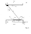
- FIG. 2 Another embodiment of the invention is shown in Fig. 2 indicated.
- a snapshot is shown shortly after the light beam L1 was first detected by a photosensitive portion 22.1 of the sensor portion 22.
- the sections are preferably separately evaluable, ie they each have individual electrical connections.
- a corresponding evaluation system 24 (or 24 and 28 in the case of Fig. 3 ) is provided to trigger an adapted response (R1, R2, R3, R4) in response to which of the sections 22.1 - 22.n the first light beam L1 strikes.
- the safety device can now be configured, programmed or set such that upon the first impact on the section 22.1 of the sensor region 22 an advance warning is issued as a reaction or the elevator installation 10 or the elevator car A1 and / or A2 is transferred to a pre-warning mode. If the light point now exceeds a predetermined further section 22.4 of the sensor region 22, a final reaction can be triggered (for example an emergency stop by triggering the brake device or the safety brake of the upper and / or the lower elevator car A1, A2). This two-step approach adds security and helps prevent false tripping.
- Fig. 3 another variant is shown. This variant is currently preferred because it offers the greatest security.
- the first detection system is designed analogously to the system shown in the preceding figures.
- the second Detection system can be identical, but sits almost mirrored in the upper part of the lower elevator car A2.
- the corresponding second sensor area 26 is seated in the lower area of the upper elevator car A1.
- the detectors trigger reactions in each case.
- the nature of the reactions differs depending on the embodiment, programming or setting of the devices.
- the detectors are capable of delivering signals or information via lines or other connections 23 or 27. These signals or information are then either processed before reactions are triggered, or they immediately trigger the responses, for example, by opening a switch that is part of a safety circuit.
- the elevator installation 10 has its own safety circuit per elevator car A1, A2, the safety circuit of the upper and / or lower elevator car A1, A2 can be interrupted by the detector (s).
- a multi-mobile elevator installation 10 preferably has one own safety circuit per elevator car A1, A2, in which several safety elements, such as safety contacts and switches, are arranged in a series connection.
- the corresponding elevator car A1 or A2 can only be moved if the safety circuit and thus also all safety contacts integrated in it are closed.
- the safety circuit is connected to the drive or the brake unit of the elevator installation 10 in order to interrupt the driving operation of the corresponding elevator car A1 or A2, if such a reaction is desired.
- the invention can also be used in elevator systems which are equipped with a safety bus system instead of the mentioned safety circuit.
- any catch brakes of the respective elevator cars A1, A2 can be triggered.
- angles W1, W2 can be adjusted in a range of 0 to 90 ° with respect to the vertical direction z.
- the angles W1, W2 are in the range between 0 and 60 degrees, and more preferably between 10 and 50 degrees.
- the angle W1, W2 as a function of individual or several parameters, such as the position, speed or acceleration of an elevator car A1, A2, the distance, relative speed or relative acceleration of the elevator car A1, A2 to a reference point or the operating state of the elevator system 10, in time set variably.
- the angle W1, W2 can be set smaller, so that the light beam L1, L2 falls on the detector 22, 24 at an earlier time and thus to it an earlier time a reaction R1, R2, R3, R4 can trigger.
- the need for an early response R1, R2, R3, R4 is reduced, and thus a larger angle W1, W2 can be set.
- the relationship between acceleration and angle is analogous.
- the angle W1, W2 of the light beam L1, L2 can be increased already after the transfer of the elevator car A1, A2 into an inspection state, since the elevator car A1, A2 can only be moved at reduced speed.
- the position of the elevator cars A1, A2 serves, for example, to determine the time of a variable adjustment of the angle W1, W2. Accordingly, a critical distance between the elevator cars A1, A2 or between an elevator car A1, A2 and the shaft end defined. If this value is undershot, the variable setting of the angle W1, W2 begins.
- corresponding sensor areas can also be provided at the lower and / or upper shaft end of the elevator shaft 11 in order to prevent a dangerous approach of an elevator car to the respective shaft end.
- the operating principle in this case is the same as described in connection with the other embodiments.
Landscapes
- Engineering & Computer Science (AREA)
- Automation & Control Theory (AREA)
- Computer Networks & Wireless Communication (AREA)
- Elevator Control (AREA)
Description
Die Erfindung betrifft eine Sicherheitseinrichtung für eine Aufzugsanlage mit mindestens einer Aufzugskabine gemäss dem Oberbegriff der unabhängigen Ansprüche. Ausserdem betrifft die Erfindung eine entsprechende Aufzugsanlage.The invention relates to a safety device for an elevator installation with at least one elevator car according to the preamble of the independent claims. In addition, the invention relates to a corresponding elevator installation.
Typischerweise sind Aufzugskabinen in einer Multimobil-Aufzugsanlagen je mit einem eigenen Antrieb und einem eigenen Bremssystem ausgestattet. Die elektronische Steuerung der gesamten Aufzugsanlage ist häufig so ausgelegt, dass es zu keinen Kollisionen der einzelnen Aufzugskabinen kommen sollte. Besonders bei einem Nothalt oder auch bei einem normalen Stockwerkhalt einer Kabine kann nicht unter allen Umständen gewährleistet werden, dass eine ober- oder unterhalb im gleichen Aufzugsschacht befindliche weitere Aufzugskabine noch rechtzeitig anhalten kann, um einen Zusammenstoss zu vermeiden. Dies könnte vermieden werden, indem man durch die Steuerung ausreichende Abstände zwischen den einzelnen Aufzugskabinen und auch entsprechend angepasste Vertikalgeschwindigkeiten vorgeben würde. Durch eine solche Vorgabe jedoch kann die Beförderungskapazität einer Multimobil-Aufzugsanlage nicht voll ausgeschöpft werden, was einen Einfluss auf die Kosten-Nutzen Effizienz hat.Typically, elevator cars in a multi-vehicle elevator system are each equipped with their own drive and their own braking system. The electronic control of the entire elevator system is often designed so that there should be no collisions of the individual elevator cars. Particularly in the case of an emergency stop or even in the case of a normal floor stop of a cabin, it can not be ensured under all circumstances that a further elevator car situated above or below the same elevator shaft can still stop in time to avoid a collision. This could be avoided by giving the controller sufficient distances between the individual elevator cars and also adapted vertical speeds. Such a requirement, however, can not fully utilize the transport capacity of a multi-vehicle elevator installation, which has an impact on the cost-benefit efficiency.
Aus der Europäischen Patentschrift
Eine ähnlich aufwendige Lösung ist aus der internationalen Patentanmeldung
Vor allem die in der internationalen Patentanmeldung
Ausserdem sind die beschriebenen Lösungen bei der Inbetriebnahme kompliziert zu initialisieren, da alle Systeme aufeinander abgestimmt werden müssen. Die Komplexität der Systeme macht diese Lösungen eventuell auch störanfällig.In addition, the described solutions are difficult to initialize during commissioning, since all systems must be coordinated. The complexity of the systems may make these solutions susceptible to interference.
Es ist in Anbetracht der bekannten Anordnungen eine erste Aufgabe der vorliegenden Erfindung, eine Multimobil-Aufzugsanlage bereit zu stellen, die bei einer Annäherung zwischen zwei Aufzugskabinen die Kabinen vor dem Auffahren selbsttätig stillgesetzt werden, ohne dass ein aufwendiger Informationsaustausch zwischen den Aufzugskabinen notwendig ist.It is in view of the known arrangements, a first object of the present invention to provide a multi-vehicle elevator system, which are automatically stopped at an approach between two elevator cars, the cabs before driving without a complex exchange of information between the elevator cars is necessary.
Eine weitere Aufgabe der vorliegenden Erfindung besteht darin in einer Aufzugsanlage mit mindestens einer Aufzugskabine, bei einer Annäherung der Aufzugskabine zu den Schachtenden, eine unerwünschte Annäherung bzw. Kollision der Kabine mit den Schachtenden zu verhindern.A further object of the present invention is to prevent an undesired approach or collision of the car with the shaft ends in an elevator installation with at least one elevator car when the elevator car approaches the shaft ends.
Mit anderen Worten ausgedrückt, geht es darum mit einfachen und zuverlässigen Mitteln die Sicherheit von Aufzugsanlagen zu verbessern.In other words, it is a question of improving the safety of elevator installations with simple and reliable means.
Die Lösung der Aufgaben erfolgt durch die Merkmale der unabhängigen Ansprüche. Vorteilhafte Weiterbildungen der Erfindung sind durch die abhängigen Patentansprüche realisiert.The solution of the objects is achieved by the features of the independent claims. Advantageous developments of the invention are realized by the dependent claims.
Die vorliegende Erfindung eignet sich gleichermassen zur Verhinderung einer Kollision zwischen zwei Aufzugskabinen, die sich relativ nähern, als auch einer zur Verhinderung einer Kollision zwischen einer Aufzugskabine und einem Schachtende. Im Folgenden werden gleichwertige Varianten der erfindungsgemässen Sicherheitseinrichtung für eine Aufzugsanlage beschrieben.The present invention is equally suitable for preventing a collision between two elevator cars that are relatively approaching and one for preventing a collision between an elevator car and a shaft end. In the following, equivalent variants of the safety device according to the invention for an elevator installation will be described.
In einer ersten Variante umfasst die Sicherheitseinrichtung für eine Aufzugsanlage mit einer oberen Aufzugskabine und einer unteren Aufzugskabine, die beide im Wesentlichen unabhängig entlang einer Vertikalrichtung in einem gemeinsamen Aufzugsschacht der Aufzugsanlage bewegbar sind, ein erstes elektro-optisches Erfassungssystem mit einer ersten Lichtquelle in einem unteren Bereich der oberen Aufzugskabine und mit einem ersten Detektor. Der erste Detektor besitzt einen lichtempfindlichen, ersten Sensorbereich in einem oberen Bereich der unteren Aufzugskabine. Die erste Lichtquelle gibt einen gebündelten ersten Lichtstrahl in einem ersten Winkel in Bezug zur Vertikalrichtung ab. Der erste Winkel ist so vorgegeben, dass bei einer Annäherung der oberen und der unteren Aufzugskabinen der erste Lichtstrahl auf den ersten Sensorbereich trifft und damit durch den ersten Detektor detektierbar ist und der erste Detektor eine Reaktion auslöst, um eine Kollision der Aufzugskabinen zu verhindern.In a first variant, the safety device for an elevator installation with an upper elevator car and a lower elevator car, both of which can be moved substantially independently along a vertical direction in a common elevator shaft of the elevator installation, comprises a first electro-optical detection system with a first light source in a lower area the upper elevator car and with a first detector. The first detector has a photosensitive, first sensor area in an upper area of the lower elevator car. The first light source outputs a collimated first light beam at a first angle with respect to the vertical direction. The first angle is predetermined so that when approaching the upper and lower elevator cars, the first light beam strikes the first sensor area and is thus detectable by the first detector and the first detector triggers a reaction to prevent a collision of the elevator cars.
Zudem verfügt die Sicherheitseinrichtung über ein zweites elektro-optisches Erfassungssystem mit einer zweiten Lichtquelle in einem oberen Bereich der unteren Aufzugskabine und über einen zweiten Detektor in einem unteren Bereich der oberen Aufzugskabine umfasst.In addition, the safety device has a second electro-optical detection system with a second light source in an upper region of the lower elevator car and a second detector in a lower region of the upper elevator car comprises.
Bei Kenntnis der vorliegenden Erfindung lässt sich die erste Variante auch mit mehr als zwei Aufzugskabinen, die im Wesentlichen unabhängig vertikal in einem gemeinsamen Aufzugsschacht verfahrbar sind, realisieren. Wobei dann zwischen jeder dieser Aufzugskabinen mindestens eine Lichtquelle und ein für diese vorgesehener Detektor vorhanden ist.With knowledge of the present invention, the first variant can also be implemented with more than two elevator cars, which can be moved substantially independently vertically in a common elevator shaft. Where then between each of these elevator cars at least one light source and provided for this detector is present.
In einer zweiten Variante umfasst die Sicherheitseinrichtung für eine Aufzugsanlage mit einem unteren Schachtende und mit mindestens einer Aufzugskabine, die im Wesentlichen unabhängig entlang einer Vertikalrichtung in einem Aufzugsschacht der Aufzugsanlage bewegbar ist, ein erstes elektro-optisches Erfassungssystem mit einer ersten Lichtquelle in einem unteren Bereich der Aufzugskabine und mit einem ersten Detektor. Der erste Detektor besitzt einen lichtempfindlichen, ersten Sensorbereich im Bereich des unteren Schachtendes. Die erste Lichtquelle gibt einen gebündelten ersten Lichtstrahl in einem ersten Winkel in Bezug zur Vertikalrichtung ab. Der erste Winkel ist so vorgegeben, dass bei einer Annäherung der Aufzugskabine mit dem unteren Schachtende der erste Lichtstrahl auf den ersten Sensorbereich trifft und damit durch den ersten Detektor detektierbar ist und der erste Detektor eine Reaktion auslöst, um eine Kollision der Aufzugskabine zu verhindern.In a second variant, the safety device for an elevator installation with a lower shaft end and with at least one elevator car, which is movable substantially independently along a vertical direction in an elevator shaft of the elevator installation, comprises a first electro-optical detection system with a first light source in a lower area of the elevator system Elevator car and with a first detector. The first detector has a photosensitive, first sensor area in the region of the lower shaft end. The first light source outputs a collimated first light beam at a first angle with respect to the vertical direction. The first angle is predetermined such that when the elevator car approaches the lower shaft end, the first light beam strikes the first sensor area and is thus detectable by the first detector and the first detector triggers a reaction to prevent a collision of the elevator car.
Zudem verfügt die Sicherheitseinrichtung über ein zweites elektro-optisches Erfassungssystem mit einer zweiten Lichtquelle im Bereich des unteren Schachtendes und über einen zweiten Detektor in einem unteren Bereich der Aufzugskabine umfasst.In addition, the safety device has a second electro-optical detection system with a second light source in the region of the lower shaft end and via a second detector in a lower region of the elevator car.
In einer dritten Variante umfasst die Sicherheitseinrichtung für eine Aufzugsanlage mit einem oberen Schachtende und mit mindestens einer Aufzugskabine, die im Wesentlichen unabhängig entlang einer Vertikalrichtung in einem Aufzugsschacht der Aufzugsanlage bewegbar ist, ein erstes elektro-optisches Erfassungssystem mit einer ersten Lichtquelle im Bereich des oberen Schachtendes und mit einem ersten Detektor. Der erste Detektor besitzt einen lichtempfindlichen, ersten Sensorbereich im oberen Bereich der Aufzugskabine. Die erste Lichtquelle gibt einen gebündelten ersten Lichtstrahl in einem ersten Winkel in Bezug zur Vertikalrichtung ab. Der erste Winkel ist so vorgegeben, dass bei einer Annäherung der Aufzugskabine mit dem oberen Schachtende der erste Lichtstrahl auf den ersten Sensorbereich trifft und damit durch den ersten Detektor detektierbar ist und der erste Detektor eine Reaktion auslöst, um eine Kollision der Aufzugskabine zu verhindern.In a third variant, the safety device for an elevator installation with an upper shaft end and with at least one elevator car, which is movable substantially independently along a vertical direction in an elevator shaft of the elevator installation, comprises a first electro-optical detection system with a first light source in the region of the upper shaft end and with a first detector. The first detector has a photosensitive, first sensor area in the upper area of the elevator car. The first light source outputs a collimated first light beam at a first angle with respect to the vertical direction. The first angle is predetermined such that, when the elevator car approaches the upper shaft end, the first light beam strikes the first sensor area and is thus detectable by the first detector and the first detector triggers a reaction to prevent a collision of the elevator car.
Zudem verfügt die Sicherheitseinrichtung über ein zweites elektro-optisches Erfassungssystem mit einer zweiten Lichtquelle in einem oberen Bereich der Aufzugskabine und über einen zweiten Detektor im Bereich des oberen Schachtendes umfasst.In addition, the safety device has a second electro-optical detection system with a second light source in an upper region of the elevator car and a second detector in the region of the upper shaft end.
Natürlich lassen sich diese Varianten vorteilhafterweise auch kombinieren, d.h. die Aufzugskabine der zweiten Variante kann die untere von mehreren Aufzugskabinen in einem gemeinsamen Aufzugsschacht der Aufzugsanlage der ersten Variante sein, die beide im Wesentlichen unabhängig entlang einer Vertikalrichtung im Aufzugsschacht bewegbar sind.Of course, these variants can advantageously also be combined, i. the elevator car of the second variant may be the lower of several elevator cars in a common elevator shaft of the elevator system of the first variant, both of which are substantially independently movable along a vertical direction in the elevator shaft.
Analog kann die Aufzugskabine der dritten Variante die obere von mehreren Aufzugskabinen in einem gemeinsamen Aufzugsschacht der Aufzugsanlage der ersten Variante sein, die beide im Wesentlichen unabhängig entlang einer Vertikalrichtung im Aufzugsschacht bewegbar sind.Analogously, the elevator car of the third variant can be the upper one of a plurality of elevator cars in a common elevator shaft of the elevator system of the first variant, both of which can be moved substantially independently along a vertical direction in the elevator shaft.
Natürlich ist auch eine Kombination aller drei Varianten in einer Aufzugsanlage möglich. Eine solche Kobination realisiert eine Verhinderung von Kollisionen der beiden Aufzugskabinen miteinander und mit Schachtenden.Of course, a combination of all three variants in an elevator system is possible. Such a combination realizes one Prevention of collisions of the two elevator cars with each other and with shaft ends.
Ein Vorteil der Erfindung ergibt sich aus der einfachen Anordnung handelsüblicher elektro-optischer Komponenten, um eine Kollision einer Aufzugskabine in einem Aufzugsschacht zu verhindern. Ein weiterer Vorteil liegt in der selbstätigen Detektion des Abstandes durch den Detektor und der Auslösung einer autonomen Reaktion bei unerwünschter Annäherung der Aufzugskabinen. Desweiteren ist der Detektor im Zusammenspiel mit einer lokalen Recheneinheit fähig mit kleinem Rechenaufwand eine kollisionsverhindernde Reaktion aufgrund von Geschwindigkeitsinformationen auszulösen. Zudem bietet die redundante Auslegung der Sicherheitseinrichtung zusätzliche Sicherheit und ermöglicht eine autonome und schnelle kollisionsverhindernde Reaktion aller Aufzugskabinen.An advantage of the invention results from the simple arrangement of commercially available electro-optical components in order to prevent a collision of an elevator car in an elevator shaft. Another advantage is the selbstätigen detection of the distance by the detector and the triggering of an autonomous reaction to unwanted approach of the elevator cars. Furthermore, the detector in conjunction with a local computing unit is capable of triggering a collision-preventing reaction based on speed information with a small amount of computation. In addition, the redundant design of the safety device provides additional security and enables an autonomous and rapid collision-preventing reaction of all elevator cars.
Im Folgenden wird die Erfindung anhand von Ausführungsbeispielen und mit Bezug auf die nicht massstäblichen Zeichnungen ausführlich beschrieben. Es zeigen:
-
Fig. 1A eine schematische, seitliche Ansicht einer ersten Multimobil-Aufzugsanlage gemäss Erfindung in einem ersten Zeitpunkt; -
Fig. 1B eine schematische, seitliche Ansicht der Multimobil-Aufzugsanlage nachFig. 1A in einem späteren Zeitpunkt; -
Fig. 2 eine schematische, seitliche Ansicht eines Teils einer zweiten Multimobil-Aufzugsanlage gemäss Erfindung; -
Fig. 3 eine schematische, seitliche Ansicht eines Teils einer dritten Multimobil-Aufzugsanlage gemäss Erfindung.
-
Fig. 1A a schematic, side view of a first multi-vehicle elevator system according to the invention in a first time; -
Fig. 1B a schematic, side view of the multi-vehicle elevator system according toFig. 1A at a later date; -
Fig. 2 a schematic, side view of a portion of a second multi-vehicle elevator installation according to the invention; -
Fig. 3 a schematic, side view of a portion of a third multi-vehicle elevator system according to the invention.
Eine erste Ausführungsform der Erfindung ist im Zusammenhang mit den beiden Momentaufnahmen in den
Es ist eine Sicherheitseinrichtung vorgesehen, die ein erstes elektro-optisches Erfassungssystem 20 mit einer ersten Lichtquelle 21 umfasst, die in einem unteren Bereich der oberen Aufzugskabine A1 angeordnet ist, wie in den
Weiterhin umfasst das Erfassungssystem 20 einen ersten Detektor 22, der einen lichtempfindlichen, ersten Sensorbereich 22 in einem oberen Bereich der unteren Aufzugskabine A2 umfasst. Als Sensorbereich 22 können Fotodioden, Fototransistoren oder andere lichtempfindliche Elemente eingesetzt werden.Furthermore, the
Die erste Lichtquelle 21 ist so ausgelegt und angeordnet, dass sie einen gebündelten ersten Lichtstrahl L1 in einem ersten Winkel W1 in Bezug zur Vertikalrichtung z in abgibt. Im gezeigten Beispiel ist der Lichtstrahl L1 abwärts gerichtet.The
In
Reduziert sich nun der relative Abstand der beiden Aufzugskabinen A1 und A2 auf einen Mindestabstand S2, wie in
Gemäss Erfindung ist der erste Winkel W1 so vorgegeben oder eingestellt, dass bei einer Annäherung der oberen und unteren Aufzugskabinen A1, A2 der erste Lichtstrahl L1 auf den ersten Sensorbereich 22 trifft, sobald der Mindestabstand S2 erreicht wird. In diesem Moment des Auftreffens ist somit der Lichtstrahl L1 durch den ersten Detektor 22, 24 detektierbar und dieser Detektor 22, 24 löst eine Reaktion R1 aus, die zum Beispiel über eine Leitung oder Verbindung 23 an eine Steuerung oder dergleichen weitergereicht wird.According to the invention, the first angle W1 is predetermined or adjusted such that, as the upper and lower elevator cars A1, A2 approach, the first light beam L1 strikes the
Die vorliegende Erfindung erlaubt nun verschiedene Realisierungsformen oder Ausbaustufen der Sicherheitseinrichtung.The present invention now permits various forms of implementation or expansion stages of the safety device.
In der einfachsten Realisierungsform kann unmittelbar beim erstmaligen Auftreffen des Lichtstrahls L1 auf den Sensorbereich 22 eine Reaktion ausgelöst werden. In diesem Fall reicht es aus, wenn der Sensorbereich 22 eine Grösse - im Sinne von Flächenausdehnung - hat, die es erlaubt sicher zu stellen, dass trotz der Schwankungen in der Aufzugsanlage 10 eine sichere Detektion des Lichtstrahls L1 durch den Detektor 22, 24 möglich ist.In the simplest form of implementation, a reaction can be triggered immediately upon first contact of the light beam L1 with the
Eine weitere Realisierungsform der Erfindung ist in
Die Abschnitte sind vorzugsweise getrennt auswertbar, d.h. sie haben jeweils einzelne elektrische Anschlüsse. Vorzugsweise ist bei den verschiedenen Ausführungsformen ein entsprechendes Auswertesystem 24 (oder 24 und 28 im Falle von
Wenn man nun die gleichen Abstände wie in den
Da sich die obere Aufzugskabine A1 weiter mit der Geschwindigkeit v1 auf die untere Kabine A2 zubewegt, verlagert sich der durch den Lichtstrahl L1 erzeugte "Lichtpunkt" nach links. Die Sicherheitseinrichtung kann nun so ausgestaltet, programmiert oder eingestellt sein, dass beim ersten Auftreffen am Abschnitt 22.1 des Sensorbereichs 22 eine Vorwarnung als Reaktion abgesetzt wird oder die Aufzugsanlage 10, respektive die Aufzugskabine A1 und/oder A2 in einen Vorwarnmodus überführt wird. Überschreitet nun der Lichtpunkt einen vorher festgelegten weiteren Abschnitt 22.4 des Sensorbereichs 22, so kann eine endgültige Reaktion ausgelöst werden (zum Beispiel ein Notstop durch Auslösen der Bremseinrichtung oder der Fangbremse der oberen und/oder der unteren Aufzugskabine A1, A2). Dieser zweistufige Ansatz bietet zusätzliche Sicherheit und hilft dadurch Fehlauslösungen zu vermeiden.Since the upper elevator car A1 continues to move toward the lower car A2 at the speed v1, the "light spot" generated by the light beam L1 shifts to the left. The safety device can now be configured, programmed or set such that upon the first impact on the section 22.1 of the
Anhand der
In
Im gezeigten Beispiel sind beide Winkel gleich, d.h. W1 = W2. Die Winkel können aber auch anders vorgegeben oder eingestellt sein. Bei identischer Ausführung der elektro-optischen Erfassungssysteme und falls W1 = W2 gilt, setzen beide elektro-optischen Erfassungssysteme zur gleichen Zeit Signale ab, oder lösen zur gleichen Zeit Reaktionen R3, R4 aus.In the example shown, both angles are equal, i. W1 = W2. The angles can also be specified or adjusted differently. If the electro-optical detection systems are identical and if W1 = W2, both electro-optical detection systems will at the same time emit signals or at the same time trigger reactions R3, R4.
In den Figuren ist schematisch angedeutet, dass die Detektoren jeweils Reaktionen auslösen. Die Art der Reaktionen unterscheidet sich je nach Ausführungsform, Programmierung oder Einstellung der Vorrichtungen. In den Figuren ist angedeutet, dass die Detektoren in der Lage sind über Leitungen oder andere Verbindungen 23 oder 27 Signale oder Informationen abzugeben. Diese Signale oder Informationen werden dann entweder verarbeitet, bevor Reaktionen ausgelöst werden, oder sie lösen unmittelbar die Reaktionen aus zum Beispiel indem sie einen Schalter öffnen, der Teil eines Sicherheitskreises ist.The figures schematically indicate that the detectors trigger reactions in each case. The nature of the reactions differs depending on the embodiment, programming or setting of the devices. In the figures, it is indicated that the detectors are capable of delivering signals or information via lines or
Es gibt zahlreiche Möglichkeiten das Auslösen der Reaktionen zu bewerkstelligen. Die jeweilige Realisierung hängt von verschiedenen Details der jeweiligen Aufzugsanlage 10 ab. Falls die Aufzugsanlage 10 zum Beispiel pro Aufzugskabine A1, A2 einen eigenen Sicherheitskreis aufweist, kann durch den/die Detektor(en) der Sicherheitskreis der oberen und/oder unteren Aufzugskabine A1, A2 unterbrochen werden.There are numerous ways to accomplish the triggering of the reactions. The particular realization depends on various details of the
Eine Multimobil-Aufzugsanlage 10 weist vorzugsweise pro Aufzugskabine A1, A2 einen eigenen Sicherheitskreis auf, bei dem mehrere Sicherheitselemente, wie zum Beispiel Sicherheitskontakte und - schalter, in einer Serienschaltung angeordnet sind. Die entsprechende Aufzugskabine A1 oder A2 kann nur bewegt werden, wenn der Sicherheitskreis und damit auch alle in ihm integrierten Sicherheitskontakte geschlossen sind. Der Sicherheitskreis steht mit dem Antrieb oder der Bremseinheit der Aufzugsanlage 10 in Verbindung, um den Fahrbetrieb der entsprechenden Aufzugskabine A1 oder A2 zu unterbrechen, falls eine solche Reaktion gewünscht ist.A
Die Erfindung kann aber auch in Aufzugsanlagen eingesetzt werden, die statt mit dem erwähnten Sicherheitskreis mit einem Sicherheitsbussystem ausgerüstet sind.However, the invention can also be used in elevator systems which are equipped with a safety bus system instead of the mentioned safety circuit.
Alternativ oder zusätzlich zum Öffnen der Sicherheitskreise können auch die Bremsen der jeweiligen Aufzugskabinen A1, A2 ausgelöst werden.Alternatively or in addition to opening the safety circuits and the brakes of the respective elevator cars A1, A2 can be triggered.
Alternativ oder zusätzlich können auch etwaige Fangbremsen der jeweiligen Aufzugskabinen A1, A2 ausgelöst werden.Alternatively or additionally, any catch brakes of the respective elevator cars A1, A2 can be triggered.
Es lassen sich also je nach Ausführungsform eine oder mehrere der folgenden Reaktionen durch die Detektoren 22, 24, bzw. 26, 28 auslösen:
- Öffnen eines Sicherheitskreises von mindestens einer Aufzugskabine A1, A2,
- Signal an eine Aufzugssteuerung,
- Auslösen einer Bremsvorrichtung von mindestens einer Aufzugskabine A1, A2,
- Auslösen einer Fangbremse von mindestens einer Aufzugskabine A1, A2,
- Überführen von mindestens einer Aufzugskabine A1, A2 in einen Vorwarnzustand,
- Anpassung der Vertikalgeschwindigkeit v1, v2 von mindestens einer Aufzugskabine A1, A2.
- Opening a safety circuit of at least one elevator car A1, A2,
- Signal to an elevator control,
- Triggering a braking device of at least one elevator car A1, A2,
- Triggering a safety brake of at least one elevator car A1, A2,
- Transferring at least one elevator car A1, A2 into a pre-warning state,
- Adaptation of the vertical speed v1, v2 of at least one elevator car A1, A2.
Man kann also mit der Erfindung eine Distanzkontrolle oder eine kombinierte Distanz- und Geschwindigkeitskontrolle realisieren.So you can realize with the invention, a distance control or a combined distance and speed control.
Die Winkel W1, W2 lassen sich in einem Bereich von 0 bis 90° bezüglich der Vertikalrichtung z einstellen. Vorzugsweise liegen die Winkel W1, W2 im Bereich zwischen 0 und 60 Grad, und besonders bevorzugt zwischen 10 und 50 Grad.The angles W1, W2 can be adjusted in a range of 0 to 90 ° with respect to the vertical direction z. Preferably, the angles W1, W2 are in the range between 0 and 60 degrees, and more preferably between 10 and 50 degrees.
Vorteilhafterweise wird der Winkel W1, W2 in Abhängigkeit von einzelnen oder mehreren Parametern, wie der Position, Geschwindigkeit oder Beschleunigung einer Aufzugskabine A1, A2, des Abstands, Relativgeschwindigkeit oder Relativbeschleunigung der Aufzugskabine A1, A2 zu einem Bezugspunkt oder des Betriebszustandes der Aufzugsanlage 10, zeitlich variabel eingestellt.Advantageously, the angle W1, W2 as a function of individual or several parameters, such as the position, speed or acceleration of an elevator car A1, A2, the distance, relative speed or relative acceleration of the elevator car A1, A2 to a reference point or the operating state of the
Dank der Einstellung des Winkels W1, W2 kann zum Beispiel bei einer grösseren Geschwindigkeit der Kabine A1, A2 der Winkel W1, W2 kleiner eingestellt werden, damit der Lichtstrahl L1, L2 zu einem früheren Zeitpunkt auf den Detektor 22, 24 fällt und somit dieser zu einem früheren Zeitpunkt eine Reaktion R1, R2, R3, R4 auslösen kann. Bei einer kleineren Geschwindigkeit reduziert sich dementsprechend die Notwendigkeit einer frühen Reaktion R1, R2, R3, R4 und somit kann ein grösserer Winkel W1, W2 eingestellt werden. Analog verhält sich der Zusammenhang zwischen Beschleunigung und Winkel.By setting the angle W1, W2, for example, at a higher speed of the car A1, A2, the angle W1, W2 can be set smaller, so that the light beam L1, L2 falls on the
Der Betriebszustand einer Aufzugsanlage 10, wie zum Beispiel im Inspektions- oder Unterhaltszustand, gibt oft eine verringerte maximale Geschwindigkeit vor. Somit kann im Fall einer Inspektionsfahrt der Aufzugskabine A1, A2 der Winkel W1, W2 des Lichtstrahls L1, L2 schon nach der Überführung der Aufzugskabine A1, A2 in einen Inspektionszustand vergrössert werden, da die Aufzugskabine A1, A2 nur mit reduzierter Geschwindigkeit verfahren werden kann.The operating condition of an
Die Position der Aufzugskabinen A1, A2 dient beispielsweise dazu den Zeitpunkt einer variablen Einstellung des Winkels W1, W2 zu bestimmen. Dementsprechend wird ein kritischer Abstand zwischen den Aufzugskabinen A1, A2 oder zwischen einer Aufzugskabine A1, A2 und dem Schachtende definiert. Wird dieser Wert unterschritten, beginnt die variable Einstellung des Winkels W1, W2.The position of the elevator cars A1, A2 serves, for example, to determine the time of a variable adjustment of the angle W1, W2. Accordingly, a critical distance between the elevator cars A1, A2 or between an elevator car A1, A2 and the shaft end defined. If this value is undershot, the variable setting of the angle W1, W2 begins.
Falls mehrere Aufzugskabinen im selben Schacht 11 verkehren, so kann auch zwischen diesen Aufzugskabinen eine entsprechende Sicherheitseinrichtung vorgesehen werden.If several elevator cars run in the
Ausserdem können auch am unteren und/oder oberen Schachtende des Aufzugsschachts 11 entsprechende Sensorbereiche vorgesehen sein, um eine gefährliche Annäherung einer Aufzugskabine an das jeweilige Schachtende zu verhindern. Das Wirkprinzip ist in diesem Fall das selbe wie im Zusammenhang mit den anderen Ausführungsformen beschrieben.In addition, corresponding sensor areas can also be provided at the lower and / or upper shaft end of the
Claims (15)
- Safety equipment for a lift installation (10) with an upper lift cage (A1) and a lower lift cage (A2), which are both movable substantially independently along a vertical direction (z) in a common lift shaft (11) of the lift installation (10), wherein the safety equipment comprises a first electro-optical detection system (20) with a first light source (21) in a lower region of the upper lift cage (A1) and with a first detector (22, 24), characterised in that- the first detector (22, 24) comprises a light-sensitive first sensor region (22) in an upper region of the lower lift cage (A2) and- the first light source (21) issues a focussed first light beam (L1) at a first angle (W1) with respect to the vertical direction (z) and the first angle (W1) is so predetermined that on approach of the upper and the lower lift cages (A1, A2) the first light beam (L1) is incident on the first sensor region (22) and thus is detectable by the first detector (22, 24) and the first detector (22, 24) triggers a reaction (R1, R2, R3, R4).
- Safety equipment (20) according to claim 1, characterised in that the safety equipment (20) comprises a second electro-optical detection system with a second light source (25) in an upper region of the lower lift cage (A2) and with a second detector (26, 28) in a lower region of the upper lift cage (A1).
- Safety equipment for a lift installation (10) with a lower shaft end and with at least one lift cage (A2), which is movable substantially independently along a vertical direction (z) in a lift shaft (11) of the lift installation (10), wherein the safety equipment comprises a first electro-optical detection system (20) with a first light source (21) in a lower region of the lift cage (A2) and with a first detector (22, 24), characterised in that- the first detector (22, 24) comprises a light-sensitive first sensor region (22) in the region of the lower shaft end and- the first light source (21) issues a focused first light beam (L1) at a first angle (W1) with respect to the vertical direction (z) and the first angle (W1) is so predetermined that on approach of the lift cage (A2) to the lower shaft end the first light beam (L1) is incident on the first sensor region (22) and thus is detectable by the first detector (22, 24) and the first detector (22, 24) triggers a reaction (R1, R2, R3, R4).
- Safety equipment (20) according to claim 3, characterised in that the safety equipment (20) comprises a second electro-optical detection system with a second light source (25) in the region of the lower shaft end and with a second detector (26, 28) in a lower region of the lift cage (A2).
- Safety equipment for a lift installation (10) with an upper shaft end and with at least one lift cage (A1), which is movable substantially independently along a vertical direction (z) in a lift shaft (11) of the lift installation (10), wherein the safety equipment comprises a first electro-optical detection system (20) with a first light source (21) in the region of the upper shaft end and with a first detector (22, 24), characterised in that- the first detector (22, 24) comprises a light-sensitive first sensor region (22) in the upper region of the lift cage (A1) and- the first light source (21) issues a focused first light beam (L1) at a first angle (W1) with respect to the vertical direction (z) and the first angle (W1) is so predetermined that on approach of the lift cage (A1, A2) to the upper shaft end the first light beam (L1) is incident on the first sensor region (22) and thus is detectable by the first detector (22, 24) and the first detector (22, 24) triggers a reaction (R1, R2, R3, R4).
- Safety equipment (20) according to claim 5, characterised in that the safety equipment (20) comprises a second electro-optical detection system with a second light source (25) in an upper region of the lift cage (A1) and with a second detector (26, 28) in the region of the upper shaft end.
- Safety equipment (20) according to claim 3 or 4, characterised in that the lift cage (A2) is the lower of several lift cages (A1, A2) in a common lift shaft (11) of the lift installation (10), which are both movable substantially independently along a vertical direction (z) in the lift shaft (11).
- Safety equipment (20) according to claim 5 or 6, characterised in that the lift cage (A1) is the upper of several lift cages (A1, A2) in a common lift shaft (11) of the lift installation (10), which are both movable substantially independently along a vertical direction (z) in the lift shaft (11).
- Safety equipment according to any one of the preceding claims, characterised in that the sensor region (22) comprises several light-sensitive sections (22.1 - 22.n) able to separately evaluated.
- Safety equipment according to any one of the preceding claims, characterised in that the first detector (22, 24) comprises an evaluating system (24) so as to be able to trigger a matched reaction (R1, R2, R3, R4) in dependence on the sections (22.1 - 22.n) on which the first light beam (L1) is incident.
- Safety equipment according to any one of the preceding claims, characterised in that one or more of the following reactions can be triggered by the first detector (22, 24):- opening a safety circuit of at least one lift cage (A1, A2),- signal to a lift control,- triggering a braking device of at least one lift cage (A1, A2),- triggering a safety brake of at least one lift cage (A1, A2),- transferring at least one lift cage (A1, A2) to a pre-warning state,- adaptation of the vertical speed (v1, v2) of at least one lift cage (A1, A2).
- Safety equipment according to any one of the preceding claims, characterised in that a spacing control or a combined spacing and speed control is realised by means of the electro-optical detection system or systems.
- Safety equipment according to any one of the preceding claims, characterised in that the angle (W1, W2) between the light beam (L1, L2) and the vertical direction (z) is settable to be variable in time in dependence on individual or several parameters.
- Safety equipment according to claim 13, characterised in that the parameters represent the position, speed or acceleration of a lift cage (A1, A2), the spacing, the relative speed or the relative acceleration of a lift cage (A1, A2) with respect to a reference point or the operational state of the lift installation (10).
- Lift installation (10) with safety equipment (20) according to any one of the preceding claims, wherein the lift installation (10) comprises at least one lift cage (A1, A2), with a drive and a holding brake per lift cage (A1, A2) and wherein a collision of the lift cages (A1, A2) can be prevented by the reaction (R1, R2, R3, R4).
Priority Applications (1)
| Application Number | Priority Date | Filing Date | Title |
|---|---|---|---|
| EP20070115231 EP1894875B1 (en) | 2006-08-31 | 2007-08-29 | Safety device for a lift facility and a lift facility with such a safety device |
Applications Claiming Priority (2)
| Application Number | Priority Date | Filing Date | Title |
|---|---|---|---|
| EP06119935A EP1894874A1 (en) | 2006-08-31 | 2006-08-31 | Safety device for an elevator |
| EP20070115231 EP1894875B1 (en) | 2006-08-31 | 2007-08-29 | Safety device for a lift facility and a lift facility with such a safety device |
Publications (2)
| Publication Number | Publication Date |
|---|---|
| EP1894875A1 EP1894875A1 (en) | 2008-03-05 |
| EP1894875B1 true EP1894875B1 (en) | 2009-08-26 |
Family
ID=38996325
Family Applications (1)
| Application Number | Title | Priority Date | Filing Date |
|---|---|---|---|
| EP20070115231 Not-in-force EP1894875B1 (en) | 2006-08-31 | 2007-08-29 | Safety device for a lift facility and a lift facility with such a safety device |
Country Status (1)
| Country | Link |
|---|---|
| EP (1) | EP1894875B1 (en) |
Families Citing this family (1)
| Publication number | Priority date | Publication date | Assignee | Title |
|---|---|---|---|---|
| CN106629315A (en) * | 2017-02-27 | 2017-05-10 | 中建三局集团有限公司 | Intelligent anti-collision buffer system for construction elevator ladder cage and implementation method |
Family Cites Families (4)
| Publication number | Priority date | Publication date | Assignee | Title |
|---|---|---|---|---|
| GB2211046A (en) * | 1987-10-10 | 1989-06-21 | Thames Valley Lift Company Lim | Lift movement monitoring |
| DE59611367D1 (en) * | 1995-10-17 | 2006-08-31 | Inventio Ag | Safety device for an elevator group |
| US6079521A (en) * | 1998-11-24 | 2000-06-27 | Otis Elevator Company | Measuring elevator position with scanning laser beam |
| US6554107B2 (en) * | 2001-09-27 | 2003-04-29 | Mitsubishi Denki Kabushiki Kaisha | Elevator system |
-
2007
- 2007-08-29 EP EP20070115231 patent/EP1894875B1/en not_active Not-in-force
Also Published As
| Publication number | Publication date |
|---|---|
| EP1894875A1 (en) | 2008-03-05 |
Similar Documents
| Publication | Publication Date | Title |
|---|---|---|
| EP1894874A1 (en) | Safety device for an elevator | |
| EP1089030B1 (en) | Device and method for monitoring a protection zone | |
| EP2022742B1 (en) | Lift system | |
| EP1404603B1 (en) | Lift installation having a virtual protection area at the bottom and/or the top of the lift shaft, and method for controlling the same | |
| EP1698580B1 (en) | Elevator system | |
| EP2250115B1 (en) | Escalator or moving walkway | |
| EP1679279B1 (en) | Elevator with control system | |
| EP1362000B1 (en) | Safety device for moveable elements, especially elevators | |
| EP2367746B1 (en) | Lift assembly | |
| EP2585395B1 (en) | Elevator system | |
| DE112013007449T5 (en) | winder | |
| EP2306063B2 (en) | Security sensor | |
| EP1905717A1 (en) | Method for operating a lift facility, a lift facility operated according to this method and a safety device for this lift facility | |
| EP3347295B1 (en) | Person transport system with a device for determining operating state | |
| EP1662349B1 (en) | Safeguarding of machines dependent on the status of the machines | |
| EP1700763A2 (en) | System for securing door closed access openings on passenger transport vehicles | |
| DE3837054C2 (en) | Hazard detection system for a vehicle, in particular an industrial truck | |
| DE60038579T2 (en) | Safety device to work on an elevator car | |
| WO1991017020A1 (en) | Transport system | |
| EP2252537B1 (en) | Measuring apparatus for an elevator system and an elevator system having such a measuring apparatus | |
| EP2319791A1 (en) | Lift assembly | |
| EP1894875B1 (en) | Safety device for a lift facility and a lift facility with such a safety device | |
| EP0280137B1 (en) | Safety device for a system employing driverless vehicles | |
| DE10104837A1 (en) | Monitoring system for control whether shortly before departure of train esp. directly after closing of doors all passengers have boarded | |
| DE102006019595B3 (en) | Safety device for making dangerous areas safe on a reel- changer has tread matting in a dangerous area for a swiveling range of a reel-arm on a reel-changer |
Legal Events
| Date | Code | Title | Description |
|---|---|---|---|
| PUAI | Public reference made under article 153(3) epc to a published international application that has entered the european phase |
Free format text: ORIGINAL CODE: 0009012 |
|
| AK | Designated contracting states |
Kind code of ref document: A1 Designated state(s): AT BE BG CH CY CZ DE DK EE ES FI FR GB GR HU IE IS IT LI LT LU LV MC MT NL PL PT RO SE SI SK TR |
|
| AX | Request for extension of the european patent |
Extension state: AL BA HR MK YU |
|
| 17P | Request for examination filed |
Effective date: 20080901 |
|
| AKX | Designation fees paid |
Designated state(s): AT BE BG CH CY CZ DE DK EE ES FI FR GB GR HU IE IS IT LI LT LU LV MC MT NL PL PT RO SE SI SK TR |
|
| REG | Reference to a national code |
Ref country code: HK Ref legal event code: DE Ref document number: 1118523 Country of ref document: HK |
|
| GRAP | Despatch of communication of intention to grant a patent |
Free format text: ORIGINAL CODE: EPIDOSNIGR1 |
|
| GRAS | Grant fee paid |
Free format text: ORIGINAL CODE: EPIDOSNIGR3 |
|
| GRAA | (expected) grant |
Free format text: ORIGINAL CODE: 0009210 |
|
| AK | Designated contracting states |
Kind code of ref document: B1 Designated state(s): AT BE BG CH CY CZ DE DK EE ES FI FR GB GR HU IE IS IT LI LT LU LV MC MT NL PL PT RO SE SI SK TR |
|
| REG | Reference to a national code |
Ref country code: GB Ref legal event code: FG4D Free format text: NOT ENGLISH |
|
| REG | Reference to a national code |
Ref country code: CH Ref legal event code: EP |
|
| REG | Reference to a national code |
Ref country code: IE Ref legal event code: FG4D Free format text: LANGUAGE OF EP DOCUMENT: GERMAN |
|
| REF | Corresponds to: |
Ref document number: 502007001385 Country of ref document: DE Date of ref document: 20091008 Kind code of ref document: P |
|
| LTIE | Lt: invalidation of european patent or patent extension |
Effective date: 20090826 |
|
| PG25 | Lapsed in a contracting state [announced via postgrant information from national office to epo] |
Ref country code: IS Free format text: LAPSE BECAUSE OF FAILURE TO SUBMIT A TRANSLATION OF THE DESCRIPTION OR TO PAY THE FEE WITHIN THE PRESCRIBED TIME-LIMIT Effective date: 20091226 Ref country code: LT Free format text: LAPSE BECAUSE OF FAILURE TO SUBMIT A TRANSLATION OF THE DESCRIPTION OR TO PAY THE FEE WITHIN THE PRESCRIBED TIME-LIMIT Effective date: 20090826 Ref country code: SE Free format text: LAPSE BECAUSE OF FAILURE TO SUBMIT A TRANSLATION OF THE DESCRIPTION OR TO PAY THE FEE WITHIN THE PRESCRIBED TIME-LIMIT Effective date: 20090826 |
|
| NLV1 | Nl: lapsed or annulled due to failure to fulfill the requirements of art. 29p and 29m of the patents act | ||
| REG | Reference to a national code |
Ref country code: ES Ref legal event code: FG2A Ref document number: 2332541 Country of ref document: ES Kind code of ref document: T3 |
|
| REG | Reference to a national code |
Ref country code: HK Ref legal event code: GR Ref document number: 1118523 Country of ref document: HK |
|
| PG25 | Lapsed in a contracting state [announced via postgrant information from national office to epo] |
Ref country code: LV Free format text: LAPSE BECAUSE OF FAILURE TO SUBMIT A TRANSLATION OF THE DESCRIPTION OR TO PAY THE FEE WITHIN THE PRESCRIBED TIME-LIMIT Effective date: 20090826 Ref country code: SI Free format text: LAPSE BECAUSE OF FAILURE TO SUBMIT A TRANSLATION OF THE DESCRIPTION OR TO PAY THE FEE WITHIN THE PRESCRIBED TIME-LIMIT Effective date: 20090826 Ref country code: NL Free format text: LAPSE BECAUSE OF FAILURE TO SUBMIT A TRANSLATION OF THE DESCRIPTION OR TO PAY THE FEE WITHIN THE PRESCRIBED TIME-LIMIT Effective date: 20090826 Ref country code: PL Free format text: LAPSE BECAUSE OF FAILURE TO SUBMIT A TRANSLATION OF THE DESCRIPTION OR TO PAY THE FEE WITHIN THE PRESCRIBED TIME-LIMIT Effective date: 20090826 |
|
| BERE | Be: lapsed |
Owner name: INVENTIO A.G. Effective date: 20090831 |
|
| PG25 | Lapsed in a contracting state [announced via postgrant information from national office to epo] |
Ref country code: PT Free format text: LAPSE BECAUSE OF FAILURE TO SUBMIT A TRANSLATION OF THE DESCRIPTION OR TO PAY THE FEE WITHIN THE PRESCRIBED TIME-LIMIT Effective date: 20091228 Ref country code: CY Free format text: LAPSE BECAUSE OF FAILURE TO SUBMIT A TRANSLATION OF THE DESCRIPTION OR TO PAY THE FEE WITHIN THE PRESCRIBED TIME-LIMIT Effective date: 20090826 Ref country code: BG Free format text: LAPSE BECAUSE OF FAILURE TO SUBMIT A TRANSLATION OF THE DESCRIPTION OR TO PAY THE FEE WITHIN THE PRESCRIBED TIME-LIMIT Effective date: 20091126 Ref country code: MC Free format text: LAPSE BECAUSE OF NON-PAYMENT OF DUE FEES Effective date: 20090831 |
|
| REG | Reference to a national code |
Ref country code: IE Ref legal event code: FD4D |
|
| PG25 | Lapsed in a contracting state [announced via postgrant information from national office to epo] |
Ref country code: RO Free format text: LAPSE BECAUSE OF FAILURE TO SUBMIT A TRANSLATION OF THE DESCRIPTION OR TO PAY THE FEE WITHIN THE PRESCRIBED TIME-LIMIT Effective date: 20090826 Ref country code: IE Free format text: LAPSE BECAUSE OF FAILURE TO SUBMIT A TRANSLATION OF THE DESCRIPTION OR TO PAY THE FEE WITHIN THE PRESCRIBED TIME-LIMIT Effective date: 20090826 Ref country code: EE Free format text: LAPSE BECAUSE OF FAILURE TO SUBMIT A TRANSLATION OF THE DESCRIPTION OR TO PAY THE FEE WITHIN THE PRESCRIBED TIME-LIMIT Effective date: 20090826 Ref country code: DK Free format text: LAPSE BECAUSE OF FAILURE TO SUBMIT A TRANSLATION OF THE DESCRIPTION OR TO PAY THE FEE WITHIN THE PRESCRIBED TIME-LIMIT Effective date: 20090826 Ref country code: CZ Free format text: LAPSE BECAUSE OF FAILURE TO SUBMIT A TRANSLATION OF THE DESCRIPTION OR TO PAY THE FEE WITHIN THE PRESCRIBED TIME-LIMIT Effective date: 20090826 |
|
| PG25 | Lapsed in a contracting state [announced via postgrant information from national office to epo] |
Ref country code: SK Free format text: LAPSE BECAUSE OF FAILURE TO SUBMIT A TRANSLATION OF THE DESCRIPTION OR TO PAY THE FEE WITHIN THE PRESCRIBED TIME-LIMIT Effective date: 20090826 |
|
| PG25 | Lapsed in a contracting state [announced via postgrant information from national office to epo] |
Ref country code: BE Free format text: LAPSE BECAUSE OF NON-PAYMENT OF DUE FEES Effective date: 20090831 |
|
| PLBE | No opposition filed within time limit |
Free format text: ORIGINAL CODE: 0009261 |
|
| STAA | Information on the status of an ep patent application or granted ep patent |
Free format text: STATUS: NO OPPOSITION FILED WITHIN TIME LIMIT |
|
| 26N | No opposition filed |
Effective date: 20100527 |
|
| PG25 | Lapsed in a contracting state [announced via postgrant information from national office to epo] |
Ref country code: GR Free format text: LAPSE BECAUSE OF FAILURE TO SUBMIT A TRANSLATION OF THE DESCRIPTION OR TO PAY THE FEE WITHIN THE PRESCRIBED TIME-LIMIT Effective date: 20091127 |
|
| PG25 | Lapsed in a contracting state [announced via postgrant information from national office to epo] |
Ref country code: AT Free format text: LAPSE BECAUSE OF NON-PAYMENT OF DUE FEES Effective date: 20090829 |
|
| PG25 | Lapsed in a contracting state [announced via postgrant information from national office to epo] |
Ref country code: IT Free format text: LAPSE BECAUSE OF FAILURE TO SUBMIT A TRANSLATION OF THE DESCRIPTION OR TO PAY THE FEE WITHIN THE PRESCRIBED TIME-LIMIT Effective date: 20090826 |
|
| PG25 | Lapsed in a contracting state [announced via postgrant information from national office to epo] |
Ref country code: MT Free format text: LAPSE BECAUSE OF FAILURE TO SUBMIT A TRANSLATION OF THE DESCRIPTION OR TO PAY THE FEE WITHIN THE PRESCRIBED TIME-LIMIT Effective date: 20090826 Ref country code: LU Free format text: LAPSE BECAUSE OF NON-PAYMENT OF DUE FEES Effective date: 20090829 |
|
| PG25 | Lapsed in a contracting state [announced via postgrant information from national office to epo] |
Ref country code: HU Free format text: LAPSE BECAUSE OF FAILURE TO SUBMIT A TRANSLATION OF THE DESCRIPTION OR TO PAY THE FEE WITHIN THE PRESCRIBED TIME-LIMIT Effective date: 20100227 |
|
| PG25 | Lapsed in a contracting state [announced via postgrant information from national office to epo] |
Ref country code: TR Free format text: LAPSE BECAUSE OF FAILURE TO SUBMIT A TRANSLATION OF THE DESCRIPTION OR TO PAY THE FEE WITHIN THE PRESCRIBED TIME-LIMIT Effective date: 20090826 |
|
| REG | Reference to a national code |
Ref country code: CH Ref legal event code: PL |
|
| PG25 | Lapsed in a contracting state [announced via postgrant information from national office to epo] |
Ref country code: CH Free format text: LAPSE BECAUSE OF NON-PAYMENT OF DUE FEES Effective date: 20110831 Ref country code: LI Free format text: LAPSE BECAUSE OF NON-PAYMENT OF DUE FEES Effective date: 20110831 |
|
| PGFP | Annual fee paid to national office [announced via postgrant information from national office to epo] |
Ref country code: ES Payment date: 20130816 Year of fee payment: 7 |
|
| PGFP | Annual fee paid to national office [announced via postgrant information from national office to epo] |
Ref country code: FR Payment date: 20130823 Year of fee payment: 7 |
|
| REG | Reference to a national code |
Ref country code: FR Ref legal event code: ST Effective date: 20150430 |
|
| PG25 | Lapsed in a contracting state [announced via postgrant information from national office to epo] |
Ref country code: FR Free format text: LAPSE BECAUSE OF NON-PAYMENT OF DUE FEES Effective date: 20140901 |
|
| REG | Reference to a national code |
Ref country code: ES Ref legal event code: FD2A Effective date: 20160226 |
|
| PG25 | Lapsed in a contracting state [announced via postgrant information from national office to epo] |
Ref country code: ES Free format text: LAPSE BECAUSE OF NON-PAYMENT OF DUE FEES Effective date: 20140830 |
|
| PGFP | Annual fee paid to national office [announced via postgrant information from national office to epo] |
Ref country code: FI Payment date: 20160811 Year of fee payment: 10 |
|
| PG25 | Lapsed in a contracting state [announced via postgrant information from national office to epo] |
Ref country code: FI Free format text: LAPSE BECAUSE OF NON-PAYMENT OF DUE FEES Effective date: 20170829 |
|
| PGFP | Annual fee paid to national office [announced via postgrant information from national office to epo] |
Ref country code: GB Payment date: 20210826 Year of fee payment: 15 Ref country code: DE Payment date: 20210827 Year of fee payment: 15 |
|
| REG | Reference to a national code |
Ref country code: DE Ref legal event code: R119 Ref document number: 502007001385 Country of ref document: DE |
|
| GBPC | Gb: european patent ceased through non-payment of renewal fee |
Effective date: 20220829 |
|
| PG25 | Lapsed in a contracting state [announced via postgrant information from national office to epo] |
Ref country code: DE Free format text: LAPSE BECAUSE OF NON-PAYMENT OF DUE FEES Effective date: 20230301 |
|
| PG25 | Lapsed in a contracting state [announced via postgrant information from national office to epo] |
Ref country code: GB Free format text: LAPSE BECAUSE OF NON-PAYMENT OF DUE FEES Effective date: 20220829 |