EP1662349B1 - Safeguarding of machines dependent on the status of the machines - Google Patents
Safeguarding of machines dependent on the status of the machines Download PDFInfo
- Publication number
- EP1662349B1 EP1662349B1 EP05109430A EP05109430A EP1662349B1 EP 1662349 B1 EP1662349 B1 EP 1662349B1 EP 05109430 A EP05109430 A EP 05109430A EP 05109430 A EP05109430 A EP 05109430A EP 1662349 B1 EP1662349 B1 EP 1662349B1
- Authority
- EP
- European Patent Office
- Prior art keywords
- machine
- sensor
- hazardous area
- area
- control system
- Prior art date
- Legal status (The legal status is an assumption and is not a legal conclusion. Google has not performed a legal analysis and makes no representation as to the accuracy of the status listed.)
- Revoked
Links
Images


Classifications
-
- B—PERFORMING OPERATIONS; TRANSPORTING
- B41—PRINTING; LINING MACHINES; TYPEWRITERS; STAMPS
- B41F—PRINTING MACHINES OR PRESSES
- B41F33/00—Indicating, counting, warning, control or safety devices
- B41F33/0018—Protection means against injury to the operator
-
- F—MECHANICAL ENGINEERING; LIGHTING; HEATING; WEAPONS; BLASTING
- F16—ENGINEERING ELEMENTS AND UNITS; GENERAL MEASURES FOR PRODUCING AND MAINTAINING EFFECTIVE FUNCTIONING OF MACHINES OR INSTALLATIONS; THERMAL INSULATION IN GENERAL
- F16P—SAFETY DEVICES IN GENERAL; SAFETY DEVICES FOR PRESSES
- F16P3/00—Safety devices acting in conjunction with the control or operation of a machine; Control arrangements requiring the simultaneous use of two or more parts of the body
- F16P3/12—Safety devices acting in conjunction with the control or operation of a machine; Control arrangements requiring the simultaneous use of two or more parts of the body with means, e.g. feelers, which in case of the presence of a body part of a person in or near the danger zone influence the control or operation of the machine
- F16P3/14—Safety devices acting in conjunction with the control or operation of a machine; Control arrangements requiring the simultaneous use of two or more parts of the body with means, e.g. feelers, which in case of the presence of a body part of a person in or near the danger zone influence the control or operation of the machine the means being photocells or other devices sensitive without mechanical contact
- F16P3/142—Safety devices acting in conjunction with the control or operation of a machine; Control arrangements requiring the simultaneous use of two or more parts of the body with means, e.g. feelers, which in case of the presence of a body part of a person in or near the danger zone influence the control or operation of the machine the means being photocells or other devices sensitive without mechanical contact using image capturing devices
-
- F—MECHANICAL ENGINEERING; LIGHTING; HEATING; WEAPONS; BLASTING
- F16—ENGINEERING ELEMENTS AND UNITS; GENERAL MEASURES FOR PRODUCING AND MAINTAINING EFFECTIVE FUNCTIONING OF MACHINES OR INSTALLATIONS; THERMAL INSULATION IN GENERAL
- F16P—SAFETY DEVICES IN GENERAL; SAFETY DEVICES FOR PRESSES
- F16P3/00—Safety devices acting in conjunction with the control or operation of a machine; Control arrangements requiring the simultaneous use of two or more parts of the body
- F16P3/12—Safety devices acting in conjunction with the control or operation of a machine; Control arrangements requiring the simultaneous use of two or more parts of the body with means, e.g. feelers, which in case of the presence of a body part of a person in or near the danger zone influence the control or operation of the machine
- F16P3/14—Safety devices acting in conjunction with the control or operation of a machine; Control arrangements requiring the simultaneous use of two or more parts of the body with means, e.g. feelers, which in case of the presence of a body part of a person in or near the danger zone influence the control or operation of the machine the means being photocells or other devices sensitive without mechanical contact
- F16P3/144—Safety devices acting in conjunction with the control or operation of a machine; Control arrangements requiring the simultaneous use of two or more parts of the body with means, e.g. feelers, which in case of the presence of a body part of a person in or near the danger zone influence the control or operation of the machine the means being photocells or other devices sensitive without mechanical contact using light grids
-
- B—PERFORMING OPERATIONS; TRANSPORTING
- B65—CONVEYING; PACKING; STORING; HANDLING THIN OR FILAMENTARY MATERIAL
- B65H—HANDLING THIN OR FILAMENTARY MATERIAL, e.g. SHEETS, WEBS, CABLES
- B65H2407/00—Means not provided for in groups B65H2220/00 – B65H2406/00 specially adapted for particular purposes
- B65H2407/10—Safety means, e.g. for preventing injuries or illegal operations
Definitions
- the present invention relates to a method and a device for safeguarding hazardous areas in machines, wherein such a dangerous area is monitored by at least one sensor which is suitable for the identification of objects penetrating into the dangerous area and is in communication with a machine control.
- a method for the constitution of two or more moving objects in a surveillance area, wherein the area to be monitored is secured by means of a horizontal light grid which consists of a plurality of mutually parallel photoelectric barriers.
- the horizontal light grid can distinguish the objects in that different criteria must be fulfilled for permitted objects. If these criteria are not fulfilled, then the evaluation of the light barrier assumes that an inadmissible object, for example an endangered person, enters the protected area.
- the criteria are the maximum size of the object, the distance or distances between the objects, as well as optionally the number of objects, the order of the objects and object movements. For object movements, these are compared with stored patterns of object movements and checked to see if they agree with allowable stored object motions.
- the publication DE 199 62 497 A1 shows a circuit arrangement for safe shutdown of a plant depending on an operating condition of the plant.
- Mcldcgcrät for monitoring the danger area is a safety photocell, which emits different signals depending on the operating condition of the system.
- the circuit constantly performs a self-test to determine that the system is working properly.
- the functionality of the device is permanently tested by means of a clock signal which is superimposed on the output signal of the signaling device such as a light barrier.
- the protective device thus always takes into account the acute injury potential for the operating personnel and only takes the machine out of operation if the potential for injury in the danger zone is actually given. This increases the availability of the machine.
- the senor is adapted to distinguish between human body parts and objects.
- this Embodiment of the invention ensures that when acute danger in the dangerous area when penetrating human body parts, the machine is immediately transferred to a safe state, while the introduction of items such. B. when changing the stack in the feeder or boom of a printing press no machine stop triggers.
- a three-dimensional scanning of the penetrating into the dangerous area object is provided.
- Such a sensor represents a 3-D camera, which allows to identify the penetrating object clearly due to its external shape design.
- 3-D camera is also possible to detect the penetrating object in its depth of penetration so that the machine is not turned off until the object has penetrated so far in the dangerous area that imminent danger is imminent.
- different penetration depths for different objects can be allowed in this manner depending on the respective operating state of the machine and the resulting different potential hazards.
- additional classes can be added in this case, in which the permitted and unauthorized objects are still classified with respect to their penetration depth depending on the respective machine state. So z.
- a light barrier or a light curtain is installed as a sensor.
- a light curtain is to be understood as meaning a plurality of light barriers arranged in a plane. Even with these light barriers, it is possible to make at least rough divisions between allowed and unauthorized objects. When using the photoelectric sensors, of course, care must be taken that objects and human body parts can always be kept perfectly separate, so that the human body parts are always assigned to unauthorized objects.
- the machine control acts on dangerous parts of the machine in the dangerous area.
- the entire machine does not have to be shut down when an unauthorized object has penetrated into the danger area, but only the dangerous parts of the machine causing the risk of injury are either shut down or brought to a safe state, so that the unauthorized object with the dangerous parts can no longer come into contact and so is protected from injury.
- the securing of the dangerous area is effected by the action of the machine control as a function of the penetration movement of the identified object determined by means of the sensor.
- the sensor it is possible to detect the movement of the object penetrating into the dangerous area. If the object moves towards the dangerous parts of the machine, the machine must be switched off or put into a safe state. If, however, the direction of movement of the object changes prior to the occurrence of an acute risk of injury, so that the movement leads away from the dangerous parts of the machine, the machine need not be switched off and can continue running instead.
- the penetration rate of the identified object can also be taken into account. If the object enters the dangerous area at a high speed, the dangerous parts of the machine or the entire machine must be switched off faster accordingly than when the object is approaching at a slow speed. This is because even with an immediate shutdown of the machine and any carried out braking the movable dangerous parts a certain caster or braking time and also Response time due to the inertia of rotating masses or moving masses in the machine must be considered.
- the securing of the dangerous area is effected by the action of the machine control as a function of the shape of the identified object detected by the sensor.
- Based on the shape of the identified object z. B. between objects and human limbs are distinguished.
- objects can be divided into different classes, so that z. B. that insertion of a stack in the feeder of a sheet-fed press is allowed, the accidental introduction of tools by the operator but also recognized and leads to machine downtime.
- the operating personnel is not only protected from hazards that occur when hitting tool on moving parts of the machine z. B. by throwing out of the tool can occur, but at the same time also the mechanics of the machine is protected, which could otherwise jam by the introduction of tools.
- the protective device is thus not only the protection of the operating personnel but also the protection of the machine.
- Fig. 1 shows a printing machine 10, which consists of a sheet feeder 11 two printing units 12 and a sheet delivery 1.
- sheet feeder 11 14 sheets 17 are removed from a feeder stack 14 by means of a suction head 18 and separated and then fed via a suction belt 19 to the printing units 12.
- the sheet 17 are transported by means of transport cylinders 16 and in printed condition passed to the boom 1.
- the transport in the boom 1 from the last printing unit 12 to the delivery stack 13 is taken over by gripper chains 15 which grab the sheet 17 on at least one side and put down on the delivery stack 13.
- the printing machine 10 is controlled in operation by the electronic machine control 5, which implements the inputs of the operating personnel.
- Both the sheet feeder 11 and the sheet delivery 1 represent a significant source of danger, since there is a considerable risk of injury to the operating personnel due to the moving components.
- the dangerous areas inside the sheet feeder 11 and the sheet delivery 1 also can not be completely blocked by mechanical protection against interference, as certain interventions for the operation of the printing press 10 are required.
- the empty pallet in the sheet feeder 11 after the exhaustion of the feeder stack 14, the empty pallet must be removed and a new feeder stack 14 is introduced.
- the change of the feeder stack 14 during operation can be made.
- the boom 1, on which the delivery stack 13 with the printed sheets must be removed at certain time intervals in order to make room for new incoming printed sheets 17.
- the operator must be offered the opportunity at certain intervals to make checks of the printed image on the sheet 17 in the delivery stack 13.
- the operator usually single sheet 17 removed from the delivery stack 13 and examined on a test panel. It must therefore be possible during operation of the printing machine 10 to be able to intervene at least in certain areas of the feeder 11 and the jib 1. For safety reasons, however, the dangerous areas in the feeder 11 and in the boom 1 must be adequately secured.
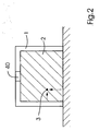
- Fig. 2 shows a way to hedge the dangerous area in the boom 1.
- the possibility shown in Fig. 2 for securing one side of the sheet delivery 1 can of course be applied to all four sides of the sheet delivery 1 and also in the sheet feeder 11 or other openings of the printing machine 10.
- Der Sheet delivery 1 has, according to FIG. 2, at least one opening 2, through which the operating personnel can engage in the dangerous area inside the jib 1. With correspondingly large printing presses 10, there is even the possibility that the operating personnel can enter the dangerous area with the whole body, in this case there is an acute danger to life. For this reason, the access opening 2 is monitored by a sensor 40 to detect the intrusion of objects or persons into the boom 1.
- a sensor 40 to detect the intrusion of objects or persons into the boom 1.
- the sensor 40 is designed as a kind of radar, which not only detects the penetration into the dangerous area, but also the exact location 3 of the penetration into the dangerous area. So the place 3 in Fig. 2 z. B. the penetration of an arm of a person who wants to engage in the interior of the boom 1. If there are no elements of the jib 1 that directly endanger the operating personnel at the location of the intervention 3, the printing press 10 does not necessarily have to be switched off. However, if the procedure is performed at a different location, eg. B. in the upper region of the opening 2, in which there is a risk that the intervening person could bring their fingers and their arm in the range of dangerous gripper chains 15, the machine 10 is stopped immediately. In addition, the operating state of the machine 10 is taken into account.
- a penetration 3 in the vicinity of the gripper chains 15 is only a danger, if they also move. If no bow 17 are promoted, the gripper chains 15 are stationary and a penetration 3 in the vicinity of the gripper chains 15 does not lead to a dangerous situation for operating personnel penetrating there, which is why a machine stop is not required in this case.
- a 3-D camera can be installed, which monitors the cross section 2 and the interior of the hazardous area. In addition to the shape and thus the identification of an intruding object 8, 13, this camera can also determine the penetration depth of the object 8, 13. Thus, movement changes of the object 8, 13 can be detected in the dangerous area. As soon as the object 8, 13 moves in the direction of the source of danger, such as the gripper chains 15, a shutdown of the printing machine 10 occurs in the event of an acute risk of injury.
- a light barrier 41 is used as the sensor 40, which likewise, like the sensor 40, is in communication with the machine control 5 of the printing machine 10 via communication connections 6.
- the light barrier 41 covers with its light beams the entire opening 2 of the feeder 1, so that the operator can not penetrate past the light rays in the interior of the boom.
- the opening 2 represents the security area 44, which is monitored for intrusion of objects 8, 13.
- the light beams of the light barrier 41 are generated by arranged on one side of the light barrier light diodes 42 to be detected on the opposite side by photodiodes 43. As soon as an object or a person wants to penetrate into the dangerous area, one or more light beams are interrupted so that no light falls on the corresponding photodiode 43.
Landscapes
- Engineering & Computer Science (AREA)
- General Engineering & Computer Science (AREA)
- Mechanical Engineering (AREA)
- Inking, Control Or Cleaning Of Printing Machines (AREA)
- Accessory Devices And Overall Control Thereof (AREA)
- Financial Or Insurance-Related Operations Such As Payment And Settlement (AREA)
- Saccharide Compounds (AREA)
- Medicines Containing Material From Animals Or Micro-Organisms (AREA)
- Pharmaceuticals Containing Other Organic And Inorganic Compounds (AREA)
Abstract
Description
Die vorliegende Erfindung betrifft ein Verfahren und eine Vorrichtung zur Absicherung gefährlicher Bereiche bei Maschinen, wobei ein solcher gefährlicher Bereich mit wenigstens einem Sensor überwacht wird, welcher zur Identifikation von in den gefährlichen Bereich eindringenden Objekten geeignet ist und mit einer Maschinensteuerung in Verbindung steht.The present invention relates to a method and a device for safeguarding hazardous areas in machines, wherein such a dangerous area is monitored by at least one sensor which is suitable for the identification of objects penetrating into the dangerous area and is in communication with a machine control.
Es sind Verfahren und Schutzvorrichtungen bekannt, mit welchen Maschinen abgesichert werden können, wobei zwischen erlaubtem und unerlaubtem Eindringen von bestimmten Objekten unterschieden werden kann. Eine derartige Vorrichtung ist aus der
Eine solche Art der Absicherung ist jedoch bei gefährlichen Bereichen bei Druckmaschinen nicht zweckmäßig, da hier im Bereich des Auslegers und des Anlegers einer Bogendruckmaschine unter bestimmten Bedingungen Eingriffe in die gefährlichen Bereiche durch das Bedienpersonals während des Betriebs erforderlich sind. Ein solches Eindringen wird jedoch durch die Lösung nach dem Stand der Technik nicht erlaubt.However, such a type of protection is not useful in hazardous areas in printing machines, since in the area of the boom and the investor of a sheetfed press under certain conditions intervention in the hazardous areas by the operating personnel during operation are required. However, such penetration is not allowed by the prior art solution.
Aus der Offenlegungsschrift
Die Offenlegungsschrift
Es ist Aufgabe der Erfindung, ein verbessertes Verfahren und eine verbesserte Vorrichtung zum Absichern gefährlicher Bereiche bei Maschinen zu schaffen, welche mit erhöhter Zuverlässigkeit zwischen erlaubtem und unerlaubtem Eindringen in den Gefahrenbereich zu unterscheiden in der Lage sind und auch das Eindringen von eigentlich unerlaubten Objekten in den gefährlichen Bereich unter bestimmten Umständen erlauben.It is the object of the invention to provide an improved method and an improved device for securing hazardous areas in machines, which with increased reliability between allowed and to allow unauthorized intrusion into the hazardous area and also allow the intrusion of actually illicit objects into the hazardous area under certain circumstances.
Erfindungsgemäß wird die Aufgabe durch Patentanspruch 1 und Patentanspruch 11 gelöst. Weitere vorteilhafte Ausgestaltungen der Erfindung sind den Unteransprüchen und den Zeichnungen zu entnehmen.According to the invention the object is achieved by
Zur Absicherung gefährlicher Bereiche bei Maschinen werden diese mit einem Sensor überwacht, welcher in der Lage ist, in den gefährlichen Bereich eindringende Objekte zu identifizieren. Damit ist es grundsätzlich möglich, zwischen Objekten zu unterscheiden, welche in den gefährlichen Bereich eindringen dürfen und verbotenen Objekten. Die erlaubten und verbotenen Objekte werden dazu in zwei Klassen eingeteilt, so dass jedes identifizierte Objekt entweder in die erlaubte oder die verbotene Klasse fällt. Solange ein erlaubtes Objekt in den gefährlichen Bereich eindringt, wie wenn z. B. ein neuer Bogenstapel in den Anleger eingebracht wird, läuft die Maschine ganz normal weiter. Dringt ein unerlaubtes Objekt in den gefährlichen Bereich ein, so würde nach dem Stand der Technik die Maschine sofort abgeschaltet. Gemäß der vorliegenden Erfindung wird nun jedoch noch der Betriebszustand der Maschine entsprechend berücksichtigt, so dass die Maschine nur dann tatsächlich abgeschaltet wird, wenn aufgrund des aktuellen Betriebszustands im gefährlichen Bereich der Maschine auch ein akute Gefahr des Bedienpersonal vorliegt. Sind z. B. bewegliche Teile im gefährlichen Bereich, welche eine Quetschgefahr für das Bedienpersonal darstellen, aufgrund des aktuellen Betriebszustands ohnehin stillgesetzt, so muss die Maschine selbst nicht stillgesetzt werden. Die Schutzvorrichtung berücksichtigt also immer das akute Verletzungspotential für das Bedienpersonal und nimmt die Maschine nur dann außer Betrieb, wenn das Verletzungspotential im Gefahrenbereich auch tatsächlich gegeben ist. Dies erhöht die Verfügbarkeit der Maschine.To protect hazardous areas of machinery, they are monitored by a sensor capable of identifying objects entering the hazardous area. This makes it fundamentally possible to distinguish between objects that are allowed to enter the dangerous area and prohibited objects. The allowed and forbidden objects are divided into two classes, so that each identified object falls into either the permitted or forbidden class. As long as a permitted object penetrates into the dangerous area, as if z. B. is introduced into the feeder, the machine continues to run normally. If an unauthorized object penetrates into the dangerous area, according to the prior art, the machine would be switched off immediately. According to the present invention, however, the operating state of the machine is now taken into account accordingly, so that the machine is actually only switched off when due to the current operating state in the dangerous area of the machine there is also an acute danger of the operating personnel. Are z. B. moving parts in the hazardous area, which constitute a risk of crushing for the operator, due to the current operating condition anyway stopped, the machine itself does not have to be shut down. The protective device thus always takes into account the acute injury potential for the operating personnel and only takes the machine out of operation if the potential for injury in the danger zone is actually given. This increases the availability of the machine.
In einer ersten Ausgestaltung der Erfindung ist vorgesehen, dass der Sensor dazu geeignet ist, zwischen menschlichen Körperteilen und Gegenständen zu unterscheiden. Mit dieser Ausgestaltung der Erfindung ist sichergestellt, dass bei akuter Gefährdung im gefährlichen Bereich beim Eindringen von menschlichen Körperteilen die Maschine sofort in einen sicheren Zustand überführt wird, während das Einbringen von Gegenständen wie z. B. beim Stapelwechsel im Anleger oder Ausleger einer Druckmaschine keinen Maschinenstopp auslöst.In a first embodiment of the invention it is provided that the sensor is adapted to distinguish between human body parts and objects. With this Embodiment of the invention ensures that when acute danger in the dangerous area when penetrating human body parts, the machine is immediately transferred to a safe state, while the introduction of items such. B. when changing the stack in the feeder or boom of a printing press no machine stop triggers.
Vorteilhafter Weise erfolgt mittels des Sensors eine dreidimensionale Abtastung des in den gefährlichen Bereich eindringenden Objekts. Ein solcher Sensor stellt eine 3-D-Kamera dar, welche es erlaubt, das eindringende Objekt aufgrund seiner äußeren Formgestaltung eindeutig zu identifizieren. Mittels einer solchen 3-D-Kamera ist weiterhin möglich, das eindringende Objekt auch in seiner Eindringtiefe zu erfassen so dass die Maschine erst dann abgestellt wird, wenn das Objekt soweit in den gefährlichen Bereich eingedrungen ist, dass unmittelbar Gefahr bevorsteht. Zudem können auf diese Art und Weise in Abhängigkeit des jeweiligen Betriebszustands der Maschine und den daraus resultierenden unterschiedlichen Gefährdungspotentialen unterschiedliche Eindringtiefen für unterschiedliche Objekte gestattet werden. Zu den zwei Klassen von erlaubten und unerlaubten Objekten können in diesem Fall weitere Klassen hinzukommen, in welchen die erlaubten und unerlaubten Objekte noch in Bezug auf ihre Eindringtiefe in Abhängigkeit des jeweiligen Maschinenzustands eingeteilt werden. So kann z. B. im Anlegerbereich, bei einer Stapeltragplatte mit dem Reststapel, die sich im oberen Bereich befindet, der untere Bereich solange für das Bedienpersonal zum Betreten frei gegeben werden, bis sich die Stapeltragplatte wieder nach unten bewegt. Wird die Bewegung der Stapeltragplatte nach unten eingeleitet, befindet sich die Maschine wieder in einem anderen Betriebszustand, welche eine sofortige Abschaltung der Maschine bewirkt, falls sich noch Bedienpersonal unterhalb der Stapeltragplatte des Anlegerstapels befinden sollte.Advantageously, by means of the sensor, a three-dimensional scanning of the penetrating into the dangerous area object. Such a sensor represents a 3-D camera, which allows to identify the penetrating object clearly due to its external shape design. By means of such a 3-D camera is also possible to detect the penetrating object in its depth of penetration so that the machine is not turned off until the object has penetrated so far in the dangerous area that imminent danger is imminent. In addition, different penetration depths for different objects can be allowed in this manner depending on the respective operating state of the machine and the resulting different potential hazards. For the two classes of permitted and unauthorized objects, additional classes can be added in this case, in which the permitted and unauthorized objects are still classified with respect to their penetration depth depending on the respective machine state. So z. As in the investor area, in a pile support plate with the remainder of the stack, which is located in the upper region, the lower area as long as the operator to enter are released until the stack support plate moves down again. If the movement of the pile support plate is initiated downward, the machine is again in a different operating state, which causes an immediate shutdown of the machine, should still be operating personnel below the stack support plate of the feeder pile.
In einer vereinfachten Ausführungsform der Erfindung ist als Sensor eine Lichtschranke oder ein Lichtvorhang installiert. Unter einem Lichtvorhang sind dabei mehrere in einer Ebene angeordnete Lichtschranken zu verstehen. Auch mit diesen Lichtschranken ist es möglich, zumindest grobe Einteilungen zwischen erlaubten und unerlaubten Objekten vorzunehmen. Beim Einsatz der Lichtschranken ist selbstverständlich darauf zu achten, dass sich Gegenstände und menschliche Körperteile immer einwandfrei auseinander halten lassen, so dass die menschlichen Körperteile immer den unerlaubten Objekten zugeordnet werden.In a simplified embodiment of the invention, a light barrier or a light curtain is installed as a sensor. A light curtain is to be understood as meaning a plurality of light barriers arranged in a plane. Even with these light barriers, it is possible to make at least rough divisions between allowed and unauthorized objects. When using the photoelectric sensors, of course, care must be taken that objects and human body parts can always be kept perfectly separate, so that the human body parts are always assigned to unauthorized objects.
In einer vorteilhaften Ausgestaltung der Erfindung ist vorgesehen, dass die Maschinensteuerung auf gefährliche Teile der Maschine im gefährlichen Bereich einwirkt. In diesem Fall muss nicht die gesamte Maschine stillgesetzt werden, wenn ein unerlaubtes Objekt in den Gefahrenbereich eingedrungen ist, sondern es werden nur die Verletzungsgefahr verursachenden gefährlichen Teile der Maschine entweder stillgesetzt oder in einen sicheren Zustand gebracht, so dass das unerlaubte Objekt mit den gefährlichen Teilen nicht mehr in Berührung kommen kann und so vor Verletzungen geschützt ist.In an advantageous embodiment of the invention, it is provided that the machine control acts on dangerous parts of the machine in the dangerous area. In this case, the entire machine does not have to be shut down when an unauthorized object has penetrated into the danger area, but only the dangerous parts of the machine causing the risk of injury are either shut down or brought to a safe state, so that the unauthorized object with the dangerous parts can no longer come into contact and so is protected from injury.
Des Weiteren kann vorgesehen sein, dass die Sicherung des gefährlichen Bereichs durch Einwirken der Maschinensteuerung in Abhängigkeit der mittels des Sensors festgestellten Eindringbewegung des identifizierten Objekts erfolgt. Mittels des Sensors ist es möglich, die Bewegung des in den gefährlichen Bereich eindringenden Objekts zu erfassen. Bewegt sich das Objekt auf die gefährlichen Teile der Maschine zu, so muss die Maschine abgeschaltet bzw. in einen sicheren Zustand versetzt werden. Sollte sich jedoch die Bewegungsrichtung des Objekts vor dem Auftreten einer akuten Verletzungsgefahr ändern, so dass die Bewegung von den gefährlichen Teilen der Maschine wegführt, so muss die Maschine nicht abgeschaltet werden und kann stattdessen weiterlaufen.Furthermore, it can be provided that the securing of the dangerous area is effected by the action of the machine control as a function of the penetration movement of the identified object determined by means of the sensor. By means of the sensor it is possible to detect the movement of the object penetrating into the dangerous area. If the object moves towards the dangerous parts of the machine, the machine must be switched off or put into a safe state. If, however, the direction of movement of the object changes prior to the occurrence of an acute risk of injury, so that the movement leads away from the dangerous parts of the machine, the machine need not be switched off and can continue running instead.
Neben der Bewegungsrichtung kann auch die Eindringgeschwindigkeit des identifizierten Objekts berücksichtigt werden. Wenn das Objekt mit einer hohen Geschwindigkeit in den gefährlichen Bereich eindringt, müssen die gefährlichen Teile der Maschine oder die gesamte Maschine entsprechend schneller abgeschaltet werden, als wenn sich das Objekt mit einer langsamen Geschwindigkeit nähert. Dies kommt daher, dass selbst bei einer sofortigen Abschaltung der Maschine und einer etwaigen durchgeführten Bremsung der beweglichen gefährlichen Teile eine gewisse Nachlauf- bzw. Bremszeit und auch Reaktionszeit aufgrund der Trägheit von rotierenden Massen oder bewegten Massen in der Maschine berücksichtigt werden muss.In addition to the direction of movement, the penetration rate of the identified object can also be taken into account. If the object enters the dangerous area at a high speed, the dangerous parts of the machine or the entire machine must be switched off faster accordingly than when the object is approaching at a slow speed. This is because even with an immediate shutdown of the machine and any carried out braking the movable dangerous parts a certain caster or braking time and also Response time due to the inertia of rotating masses or moving masses in the machine must be considered.
Weiterhin kann vorgesehen sein, dass die Sicherung des gefährlichen Bereichs durch Einwirkung der Maschinensteuerung in Abhängigkeit der mittels des Sensors erkannten Form des identifizierten Objekts erfolgt. Anhand der Form des identifizierten Objekts kann z. B. zwischen Gegenständen und menschlichen Gliedmaßen unterschieden werden. Außerdem können auch Gegenstände in unterschiedliche Klassen eingeteilt werden, so dass z. B. dass Einbringen eines Stapels in den Anleger einer Bogendruckmaschine erlaubt wird, das versehentliche Einbringen von Werkzeug durch das Bedienpersonal aber auch erkannt wird und zum Maschinenstillstand führt. In diesem Fall wird das Bedienpersonal nicht nur vor Gefahren geschützt, welche beim Auftreffen von Werkzeug auf bewegliche Teile der Maschine z. B. durch ein Herausschleudern des Werkzeugs auftreten können, sondern zugleich wird auch die Mechanik der Maschine geschützt, welche sich sonst durch das Einbringen von Werkzeug verklemmen könnte. In diesem Fall dient die Schutzvorrichtung also nicht nur dem Schutz des Bedienpersonals sondern auch dem Schutz der Maschine.Furthermore, it can be provided that the securing of the dangerous area is effected by the action of the machine control as a function of the shape of the identified object detected by the sensor. Based on the shape of the identified object z. B. between objects and human limbs are distinguished. In addition, objects can be divided into different classes, so that z. B. that insertion of a stack in the feeder of a sheet-fed press is allowed, the accidental introduction of tools by the operator but also recognized and leads to machine downtime. In this case, the operating personnel is not only protected from hazards that occur when hitting tool on moving parts of the machine z. B. by throwing out of the tool can occur, but at the same time also the mechanics of the machine is protected, which could otherwise jam by the introduction of tools. In this case, the protective device is thus not only the protection of the operating personnel but also the protection of the machine.
Die vorliegende Erfindung wird nun anhand mehrerer Figuren näher beschrieben und erläutert. Es zeigen:
- Fig. 1: eine Bogenrotationsdruckmaschine mit einem Anleger und einem Ausleger,
- Fig. 2: einen überwachten gefährlichen Bereich am Ausleger und
- Fig. 3: den Einsatz einer Lichtschranke zur Überwachung des gefährlichen Bereichs am Ausleger einer Druckmaschine.
- 1: a sheet-fed rotary printing machine with a feeder and a boom,
- Fig. 2: a monitored hazardous area on the boom and
- Fig. 3: the use of a light barrier to monitor the hazardous area on the boom of a printing press.
Fig. 1 zeigt eine Druckmaschine 10, welche aus einem Bogenanleger 11 zwei Druckwerken 12 und einem Bogenausleger 1 besteht. Im Bogenanleger 11 werden von einem Anlegerstapel 14 Bogen 17 mittels eines Saugkopfs 18 entnommen und vereinzelt und dann über einen Saugbändertisch 19 den Druckwerken 12 zugeführt. Durch die Druckwerke 12 werden die Bogen 17 mittels Transportzylindern 16 transportiert und im bedruckten Zustand an den Ausleger 1 übergeben. Der Transport im Ausleger 1 vom letzten Druckwerk 12 bis zum Auslegerstapel 13 wird dabei von Greiferketten 15 übernommen, welche den Bogen 17 an wenigstens einer Seite ergreifen und auf dem Auslegerstapel 13 ablegen. Die Druckmaschine 10 wird im Betrieb durch die elektronische Maschinensteuerung 5 gesteuert, welche die Eingaben des Bedienpersonals umsetzt.Fig. 1 shows a
Sowohl der Bogenanleger 11 als auch der Bogenausleger 1 stellen eine erhebliche Gefahrenquelle dar, da aufgrund der sich bewegenden Bauteile eine erhebliche Verletzungsgefahr für das Bedienpersonal besteht. Auf der anderen Seite können die gefährlichen Bereiche im Inneren des Bogenanlegers 11 und des Bogenauslegers 1 auch nicht einfach durch mechanische Schutzvorrichtung gegen Eingriffe völlig gesperrt werden, da gewisse Eingriffe zum Betrieb der Druckmaschine 10 erforderlich sind. So muss im Bogenanleger 11 nach dem Aufbrauchen des Anlegerstapels 14 die leere Palette entnommen werden und ein neuer Anlegerstapel 14 eingebracht werden. Um den Betrieb der Druckmaschine 10 nicht zu unterbrechen, kann der Wechsel des Anlegerstapels 14 bei laufendem Betrieb vorgenommen werden. Ähnliches gilt für den Ausleger 1, an dem der Auslegerstapel 13 mit den bedruckten Bogen in bestimmten zeitlichen Abständen entnommen werden muss, um Platz für neue ankommende bedruckte Bogen 17 zu schaffen. Außerdem muss dem Bedienpersonal die Möglichkeit geboten werden, in bestimmten zeitlichen Abständen Kontrollen des Druckbilds auf den Bogen 17 im Auslegerstapel 13 vorzunehmen. Zu diesem Zweck werden vom Bedienpersonal meist einzelne Bogen 17 aus dem Auslegerstapel 13 entnommen und auf einem Prüfpult begutachtet. Es muss also während des Betriebs der Druckmaschine 10 möglich sein, zumindest in bestimmte Bereiche des Anlegers 11 und des Auslegers 1 eingreifen zu können. Aus Sicherheitsgründen müssen jedoch die gefährlichen Bereiche im Anleger 11 und im Ausleger 1 entsprechend abgesichert werden.Both the
Fig. 2 zeigt eine Möglichkeit, den gefährlichen Bereich im Ausleger 1 abzusichern. Die in Fig. 2 gezeigte Möglichkeit zur Absicherung einer Seite des Bogenauslegers 1 kann selbstverständlich auf allen vier Seiten des Bogenauslegers 1 angewandt werden und ebenso im Bogenanleger 11 oder an anderen Öffnungen der Druckmaschine 10. Der Bogenausleger 1 weist gemäß Fig. 2 wenigstens eine Öffnung 2 auf, durch welche das Bedienpersonal in den gefährlichen Bereich im Inneren des Auslegers 1 eingreifen kann. Bei entsprechend großen Druckmaschinen 10 besteht sogar die Möglichkeit, dass das Bedienpersonal den gefährlichen Bereich mit dem ganzen Körper betreten kann, hier besteht dann akute Lebensgefahr. Aus diesem Grund wird die Zutrittsöffnung 2 mittels eines Sensors 40 überwacht, um das Eindringen von Gegenständen oder Personen in den Ausleger 1 zu detektieren. In Fig. 2 ist der Sensor 40 als eine Art Radar ausgeführt, welches nicht nur das Eindringen in den gefährlichen Bereich feststellt, sondern auch den genauen Ort 3 des Eindringens in den gefährlichen Bereich. So gibt der Ort 3 in Fig. 2 z. B. den Eindringort eines Arms einer Person an, welche in das Innere des Auslegers 1 eingreifen möchte. Befinden sich an dem Ort des Eingriffs 3 keine unmittelbar das Bedienpersonal gefährdenden Elemente des Auslegers 1, so muss die Druckmaschine 10 nicht notwendigerweise abgeschaltet werden. Erfolgt der Eingriff jedoch an einem anderen Ort, z. B. im oberen Bereich der Öffnung 2, in dem die Gefahr besteht, dass die eingreifende Person ihre Finger und ihren Arm in den Bereich der gefährlichen Greiferketten 15 bringen könnte, so wird die Maschine 10 sofort stillgesetzt. Zusätzlich wird noch der Betriebszustand der Maschine 10 mit berücksichtigt. So stellt ein Eindringort 3 in der Nähe der Greiferketten 15 nur dann eine Gefahr dar, wenn sich diese auch bewegen. Wenn keine Bogen 17 gefördert werden, stehen die Greiferketten 15 still und ein Eindringort 3 in der Nähe der Greiferketten 15 führt nicht zu einer gefährlichen Situation für dort eindringendes Bedienpersonal, weshalb ein Maschinenstopp in diesem Fall nicht erforderlich ist.Fig. 2 shows a way to hedge the dangerous area in the
In einer alternativen Ausgestaltung kann auch vorgesehen sein, dass nur die Greiferketten am Ausleger 15 abgeschaltet werden, wenn diese über einen separaten Antrieb verfügen. Wenn die Maschinensteuerung 5 in Abhängigkeit des durch den Sensor 40 ermittelten Eindringorts 3 keine unmittelbare Gefahr für das Bedienpersonal erkennen kann, so kann trotzdem ein akustischer oder optischer Alarm ausgegeben werden, um das Bedienpersonal auf das Eindringen in den gefährlichen Bereich hinzuweisen.In an alternative embodiment, it can also be provided that only the gripper chains on the
An Stelle des Sensors 40 kann auch eine 3-D-Kamera installiert sein, welche den Querschnitt 2 und den Innenraum des gefährlichen Bereichs überwacht. Diese Kamera kann neben der Form und damit der Identifikation eines eindringenden Objekts 8, 13 auch die Eindringtiefe des Objekts 8, 13 ermitteln. Somit können auch Bewegungsänderungen des Objekts 8, 13 im gefährlichen Bereich erkannt werden. Sobald sich das Objekt 8, 13 in Richtung auf die Gefahrenquelle wie die Greiferketten 15 zu bewegt, erfolgt bei akuter Verletzungsgefahr eine Abschaltung der Druckmaschine 10.In place of the
In einer Ausführungsform gemäß Fig. 3 wird als Sensor 40 eine Lichtschranke 41 eingesetzt, welche ebenfalls wie der Sensor 40 über Kommunikationsverbindungen 6 mit der Maschinensteuerung 5 der Druckmaschine 10 in Verbindung steht. Die Lichtschranke 41 bedeckt mit ihren Lichtstrahlen die gesamte Öffnung 2 des Anlegers 1, so dass das Bedienpersonal nicht an den Lichtstrahlen vorbei in das Innere des Auslegers eindringen kann. Damit stellt die Öffnung 2 den Sicherheitsbereich 44 dar, welcher auf ein Eindringen von Objekten 8, 13 überwacht wird. Die Lichtstrahlen der Lichtschranke 41 werden dabei von auf der einen Seite der Lichtschranke angeordneten Lichtdioden 42 erzeugt, um auf der gegenüberliegenden Seite durch Fotodioden 43 erfasst zu werden. Sobald ein Gegenstand oder eine Person in den gefährlichen Bereich eindringen möchte, werden ein oder mehrere Lichtstrahlen unterbrochen, so dass auf die entsprechende Fotodiode 43 kein Licht mehr fällt. Auf diese Art und Weise ist es möglich, festzustellen, welcher der Lichtstrahlen tatsächlich unterbrochen wurde. Das Eindringen einer Hand 8 des Bedienpersonals unterbricht dabei weniger Lichtstrahlen als das Eindringen oder Entfernen des gesamten Auslegerstapels 13. Dringt das Bedienpersonal mit seiner Hand 8 durch die Öffnung 2 im Ausleger 1, so wird wenigstens einer der Lichtstrahlen der Lichtschranke 41 unterbrochen. Die Position dieses Lichtstrahls wird an die Maschinensteuerung 5 übertragen, welche dann in Abhängigkeit der festgestellten Position des Lichtstrahls entsprechende Maßnahmen ergreift. Stellt das Durchdringen dieses Lichtstrahls keine potentielle Verletzungsgefahr dar, so stellt die Maschinensteuerung 5 die Druckmaschine 10 bzw. den Ausleger 1 nicht ab und kann stattdessen ein akustisches oder optisches Warnsignal ausgeben. Wird durch die Hand 8 des Bedieners jedoch ein Lichtstrahl unterbrochen, hinter dem eine unmittelbare Verletzungsgefahr droht, so gibt die Maschinensteuerung 5 ein entsprechendes Kommando an den Antrieb der Druckmaschine 10, welcher daraufhin sofort stillgesetzt wird. Die Lichtschranke 41 mit einzeln auswertbaren Lichtstrahlen ermöglicht es so, den Sicherheitsbereich 44 der Öffnung 2 ortsabhängig auszuwerten. Dabei wird je nach Maschinenzustand unterschieden ob ein Verdecken eines Lichtstrahls durch ein eindringendes Objekt zu einer Gefahrensituation führt oder nicht. Bewegen sich z.B. die Greiferketten 15 im Ausleger 1 nicht, so führt ein Unterbrechen der Lichtstrahlen im oberen Bereich des Auslegers 1 nicht zum Maschinenstillstand. Droht jedoch eine Gefahr durch den Auslegerstapel 13, weil dieser sich ebenfalls im oberen Bereich befindet, so führt eine Unterbrechung desselben Lichtstrahls zum Maschinenstopp. Die Berücksichtigung des Betriebszustands der Maschine erlaubt eine bessere Verfügbarkeit der Maschine, da nur noch dann abgeschaltet werden muss, wenn dies unbedingt notwendig ist.In an embodiment according to FIG. 3, a
- 11
- Auslegerboom
- 22
- Öffnung im AuslegerOpening in the boom
- 33
- Ortskoordinaten des EintrittsLocation coordinates of entry
- 55
- Maschinensteuerungmachine control
- 66
- Kommunikationsverbindungcommunication link
- 88th
- Handhand
- 1010
- Druckmaschinepress
- 1111
- Anleger der DruckmaschineFeeder of the printing press
- 1212
- Druckwerkprinting unit
- 1313
- Auslegerstapeldelivery pile
- 1414
- Anlegerstapelfeeder pile
- 1515
- Greiferketten im AuslegerGripper chains in the boom
- 1616
- Transportzylindertransport cylinder
- 1717
- Bogenbow
- 1818
- Saugkopfsuction head
- 1919
- Saugbändertischfeed table
- 4040
- Sensorsensor
- 4141
- Lichtschrankephotocell
- 4242
- Leuchtdiodeled
- 4343
- Fotodiodephotodiode
- 4444
- Sicherheitsbereichsecurity area
Claims (8)
- Method of safeguarding hazardous areas in machines (1, 10, 11), such a hazardous area being monitored by at least one sensor (40, 41) suitable for identifying objects (8, 13) that penetrate into the hazardous area and provided with a connection (6) to a machine control system (5), and, upon penetration of an object (8, 13) into the hazardous area, this object (8, 13) being identified by means of the sensor (40, 41), and a state of the hazardous area in the machine (1, 10, 11) being influenced by means of the machine control system (5) as a function of the identification and of the respective operating condition of the machine (1, 10, 11),
characterized in
that the sensor (40, 41) carries out a three-dimensional scanning of the object (8, 13) that penetrates into the hazardous area. - Method according to Claim 1,
characterized in
that the sensor (40) is a 3-D camera. - Method according to any one of the preceding claims,
characterized in
that the machine control system (5) acts on hazardous parts (15) of the machine (1, 10, 11) in the hazardous area. - Method according to Claim 3,
characterized in
that the machine control system (5) brings hazardous parts (15) of the machine (1, 10, 11) in the hazardous area into a safe state. - Method according to any one of the preceding claims,
characterized in
that the safeguarding of the hazardous area is carried out by an action of the machine control system (5) as a function of the penetrating movement of the identified object (8, 13) as detected by the sensor (40, 41). - Method according to Claim 5,
characterized in
that the acting on the hazardous area by means of the machine control system (5) is carried out as a function of the detected penetration speed of the identified object (8, 13). - Method according to any one of claims 1 to 5,
characterized in
that the safeguarding of the hazardous area by means of an action of the machine control system (5) is carried out as a function of the shape of the identified object (8, 13) as detected by the sensor (40, 41). - Printing press (10) wherein a hazardous area (1, 11) of the printing press is monitored by at least one sensor (40, 41) provided for identifying objects (8, 13) that penetrate into the hazardous area and connected to a machine control system (5) of the printing press (10) and wherein, upon penetration of the object (8, 13) into the hazardous area, the object (8, 13) is identified by the sensor (40, 41) and the machine control system (5) of the printing press (10) acts on the state of the hazardous area of the printing press (1, 10, 11) as a function of the identification and the respective operating condition,
characterized in
that the sensor (40, 41) is provided for the three-dimensional scanning of the object (8, 13) penetrating into the hazardous area.
Applications Claiming Priority (1)
| Application Number | Priority Date | Filing Date | Title |
|---|---|---|---|
| DE102004055229A DE102004055229A1 (en) | 2004-11-17 | 2004-11-17 | Dangerous zone e.g. sheet feeder, securing method for printing machine, involves affecting object based on operating condition of machine and identification of object in zone by sensor that differentiates human body part and article |
Publications (2)
| Publication Number | Publication Date |
|---|---|
| EP1662349A1 EP1662349A1 (en) | 2006-05-31 |
| EP1662349B1 true EP1662349B1 (en) | 2008-01-09 |
Family
ID=35457871
Family Applications (1)
| Application Number | Title | Priority Date | Filing Date |
|---|---|---|---|
| EP05109430A Revoked EP1662349B1 (en) | 2004-11-17 | 2005-10-11 | Safeguarding of machines dependent on the status of the machines |
Country Status (6)
| Country | Link |
|---|---|
| US (1) | US20060114323A1 (en) |
| EP (1) | EP1662349B1 (en) |
| JP (1) | JP2006142822A (en) |
| CN (1) | CN100543356C (en) |
| AT (1) | ATE383601T1 (en) |
| DE (2) | DE102004055229A1 (en) |
Families Citing this family (19)
| Publication number | Priority date | Publication date | Assignee | Title |
|---|---|---|---|---|
| JP2007223171A (en) * | 2006-02-23 | 2007-09-06 | Mitsubishi Heavy Ind Ltd | Printing machine and delivery equipment of printing machine |
| JP2008105303A (en) * | 2006-10-26 | 2008-05-08 | Komori Corp | Rotor protecting apparatus |
| DE102007013299A1 (en) * | 2007-03-06 | 2008-09-11 | Cedes Ag | Sensor device and system with a conveyor and a sensor device |
| JP5116148B2 (en) * | 2007-11-30 | 2013-01-09 | パナソニック デバイスSunx株式会社 | Multi-optical axis photoelectric switch, controller and printing system |
| DE102008041850B4 (en) * | 2008-09-05 | 2012-03-22 | Koenig & Bauer Aktiengesellschaft | Printing unit of a printing press with at least two relatively mutually positionally adjustable frame parts |
| DE102008042813A1 (en) * | 2008-10-14 | 2010-04-22 | Koenig & Bauer Aktiengesellschaft | Dangerous area protection for the area of automatic roll loading on a roll changer |
| JP5468810B2 (en) * | 2009-04-23 | 2014-04-09 | 株式会社小森コーポレーション | Sheet loader |
| EP2437593B1 (en) * | 2009-06-05 | 2017-03-01 | DeLaval Holding AB | Safety system |
| DE102009031226B4 (en) * | 2009-07-01 | 2016-06-30 | Sick Ag | Safety Light Curtain |
| EP2363768B1 (en) | 2010-01-27 | 2012-10-10 | Umberto Calliari | Safety brake device for moving machine elements |
| JP6509567B2 (en) * | 2015-01-16 | 2019-05-08 | 株式会社日商グラビア | Calibrator with multiple plate cylinders |
| US10834065B1 (en) | 2015-03-31 | 2020-11-10 | F5 Networks, Inc. | Methods for SSL protected NTLM re-authentication and devices thereof |
| CN107209498B (en) * | 2015-04-24 | 2021-07-13 | 惠普发展公司有限责任合伙企业 | Method of generating a three-dimensional object model for an additive manufacturing process |
| US10404698B1 (en) | 2016-01-15 | 2019-09-03 | F5 Networks, Inc. | Methods for adaptive organization of web application access points in webtops and devices thereof |
| MX2018014125A (en) * | 2016-05-18 | 2019-04-29 | Bobst Grenchen Ag | Control system for a functional section of a paper processing device. |
| DE102017119275B4 (en) * | 2017-08-23 | 2019-07-25 | Sick Ag | light curtain |
| DE102017218917A1 (en) * | 2017-10-24 | 2019-04-25 | Robert Bosch Gmbh | Monitoring device, industrial plant, monitoring method and computer program |
| KR20240074933A (en) * | 2022-11-14 | 2024-05-29 | (주)아이티공간 | Device safety accident prevention system using virtual fence and skeleton image |
| KR20240070752A (en) * | 2022-11-14 | 2024-05-22 | (주)아이티공간 | Device safety accident prevention system using virtual fence and skeleton image |
Family Cites Families (19)
| Publication number | Priority date | Publication date | Assignee | Title |
|---|---|---|---|---|
| DE4016169A1 (en) * | 1990-05-19 | 1991-11-21 | Darko Dipl Ing Drazic | Contactless safety and control arrangement for dangerous machinery - includes reader of code cards carried by operators for identification by processor in command of relays |
| JPH09174820A (en) * | 1995-12-28 | 1997-07-08 | Mitsubishi Heavy Ind Ltd | Automatic plate replacing safety device for printer |
| US6297844B1 (en) * | 1999-11-24 | 2001-10-02 | Cognex Corporation | Video safety curtain |
| DE19962497A1 (en) * | 1999-12-23 | 2001-07-05 | Pilz Gmbh & Co | Circuit arrangement for safely switching off a system, in particular a machine system |
| DE10000287B4 (en) * | 2000-01-07 | 2004-02-12 | Leuze Lumiflex Gmbh + Co. Kg | Device and method for monitoring a detection area on a work equipment |
| DE10002085A1 (en) * | 2000-01-19 | 2001-08-02 | Fraunhofer Ges Forschung | Object monitoring method involves recognizing and summarizing picture elements having same characteristics, deriving classification features from object areas, and performing further processing |
| DE10120773A1 (en) * | 2000-04-26 | 2001-10-31 | Visolux Zweigniederlassung Der | Image processing arrangement for preventing accidents has image processing device with mutually independent image signal processing channels connected to external process switches |
| US6829371B1 (en) * | 2000-04-29 | 2004-12-07 | Cognex Corporation | Auto-setup of a video safety curtain system |
| JP2002036510A (en) * | 2000-05-16 | 2002-02-05 | Komori Corp | Safety device for rotary press |
| DE60102177T2 (en) * | 2000-05-16 | 2005-01-13 | Komori Corporation | Safety device for a web-fed rotary press |
| DE10026305A1 (en) * | 2000-05-26 | 2001-11-29 | Sick Ag | Opto-electronic device for monitoring protection region, has image determination unit which picks-up planar or spatial image of monitoring regions that lay near and outside the protection region |
| PL367674A1 (en) * | 2001-06-22 | 2005-03-07 | Pfizer Products Inc. | Pharmaceutical compositions of adsorbates of amorphous drug |
| DE10152543A1 (en) * | 2001-10-24 | 2003-05-08 | Sick Ag | Method and device for controlling a safety-relevant function of a machine |
| JP4481549B2 (en) * | 2002-03-04 | 2010-06-16 | 株式会社キーエンス | Multi-optical axis photoelectric safety device |
| DE10216122A1 (en) * | 2002-04-12 | 2003-10-30 | Sick Ag | object detection |
| DE10221578A1 (en) * | 2002-05-08 | 2003-11-27 | Siemens Ag | Dangerous area surveillance sensor has 3D-CMOS sensor with pulsed laser light source |
| DE10251584B4 (en) * | 2002-11-06 | 2004-11-04 | Leuze Lumiflex Gmbh + Co. Kg | Method and device for monitoring a detection area |
| US6856862B1 (en) * | 2003-03-18 | 2005-02-15 | Xilinx, Inc. | Light curtain safety system for semiconductor device handler |
| JP4374609B2 (en) * | 2004-02-20 | 2009-12-02 | オムロン株式会社 | People counting device |
-
2004
- 2004-11-17 DE DE102004055229A patent/DE102004055229A1/en not_active Ceased
-
2005
- 2005-10-11 AT AT05109430T patent/ATE383601T1/en not_active IP Right Cessation
- 2005-10-11 EP EP05109430A patent/EP1662349B1/en not_active Revoked
- 2005-10-11 DE DE502005002482T patent/DE502005002482D1/en active Active
- 2005-11-14 JP JP2005328610A patent/JP2006142822A/en active Pending
- 2005-11-17 US US11/281,350 patent/US20060114323A1/en not_active Abandoned
- 2005-11-17 CN CNB2005101250804A patent/CN100543356C/en not_active Expired - Fee Related
Also Published As
| Publication number | Publication date |
|---|---|
| US20060114323A1 (en) | 2006-06-01 |
| CN1776282A (en) | 2006-05-24 |
| DE102004055229A1 (en) | 2006-05-18 |
| ATE383601T1 (en) | 2008-01-15 |
| CN100543356C (en) | 2009-09-23 |
| EP1662349A1 (en) | 2006-05-31 |
| JP2006142822A (en) | 2006-06-08 |
| DE502005002482D1 (en) | 2008-02-21 |
Similar Documents
| Publication | Publication Date | Title |
|---|---|---|
| EP1662349B1 (en) | Safeguarding of machines dependent on the status of the machines | |
| EP1306603B2 (en) | Process and device for controlling a safety-relevant function of a machine | |
| EP1367314B1 (en) | Device for monitoring the operating range of working means | |
| DE102005050824A1 (en) | Dangerous area protecting method for use in sheet rotation printing machine, involves monitoring dangerous area by sensor, detecting position of object penetrating cross section and activating machine based on detected position | |
| EP1353196B1 (en) | Object detection and light curtain | |
| DE10251584B4 (en) | Method and device for monitoring a detection area | |
| DE102006052017B4 (en) | processing machine | |
| EP3425256B1 (en) | Access protection system | |
| EP2017524B1 (en) | Light grid | |
| EP2306063B1 (en) | Security sensor | |
| EP2660012A2 (en) | Monitoring device for monitoring positions of a robot and manufacturing plant with a monitoring device | |
| DE10143505A1 (en) | Security method and optoelectronic sensor | |
| DE102019116806B4 (en) | Device and method for monitoring a hazardous area | |
| EP3696461A2 (en) | Safety device for a machine and operation method | |
| DE202017103399U1 (en) | Access protection system | |
| DE102008033195B4 (en) | Machining center with a workpiece transport device and a workpiece supply station with opto-electronic protective device | |
| AT500402B1 (en) | SAFETY DEVICE IN AN ARC TOOL | |
| DE102006019595B3 (en) | Safety device for making dangerous areas safe on a reel- changer has tread matting in a dangerous area for a swiveling range of a reel-arm on a reel-changer | |
| DE10310236B3 (en) | Safety device for printing machine sheet delivery station has input device allowing access to sheet stack by operator by temporary de-activation of coupling between safety device and sheet conveyor drive | |
| EP3767152B1 (en) | Securing device for a machine and method for operating a securing device | |
| EP3217063A1 (en) | Safety device for a palletizer and system with a palletiser and a safety device and method | |
| DE102006002356A1 (en) | Method for protection of hazardous areas especially of sheet-fed printing presses entails sensing of loads conveyed to and from press and producing control signals which are evaluated according to predetermined criteria | |
| DE102017119275B4 (en) | light curtain | |
| DE102016117018A1 (en) | Safety device for a palletizer and system with a palletizer and a safety device, and method | |
| DE102016122650B4 (en) | robot security system |
Legal Events
| Date | Code | Title | Description |
|---|---|---|---|
| PUAI | Public reference made under article 153(3) epc to a published international application that has entered the european phase |
Free format text: ORIGINAL CODE: 0009012 |
|
| AK | Designated contracting states |
Kind code of ref document: A1 Designated state(s): AT BE BG CH CY CZ DE DK EE ES FI FR GB GR HU IE IS IT LI LT LU LV MC NL PL PT RO SE SI SK TR |
|
| AX | Request for extension of the european patent |
Extension state: AL BA HR MK YU |
|
| 17P | Request for examination filed |
Effective date: 20061130 |
|
| 17Q | First examination report despatched |
Effective date: 20070103 |
|
| AKX | Designation fees paid |
Designated state(s): AT BE BG CH CY CZ DE DK EE ES FI FR GB GR HU IE IS IT LI LT LU LV MC NL PL PT RO SE SI SK TR |
|
| GRAP | Despatch of communication of intention to grant a patent |
Free format text: ORIGINAL CODE: EPIDOSNIGR1 |
|
| GRAS | Grant fee paid |
Free format text: ORIGINAL CODE: EPIDOSNIGR3 |
|
| GRAA | (expected) grant |
Free format text: ORIGINAL CODE: 0009210 |
|
| AK | Designated contracting states |
Kind code of ref document: B1 Designated state(s): AT BE BG CH CY CZ DE DK EE ES FI FR GB GR HU IE IS IT LI LT LU LV MC NL PL PT RO SE SI SK TR |
|
| REG | Reference to a national code |
Ref country code: GB Ref legal event code: FG4D Free format text: NOT ENGLISH |
|
| REG | Reference to a national code |
Ref country code: CH Ref legal event code: EP |
|
| REG | Reference to a national code |
Ref country code: IE Ref legal event code: FG4D Free format text: LANGUAGE OF EP DOCUMENT: GERMAN |
|
| GBT | Gb: translation of ep patent filed (gb section 77(6)(a)/1977) |
Effective date: 20080130 |
|
| REF | Corresponds to: |
Ref document number: 502005002482 Country of ref document: DE Date of ref document: 20080221 Kind code of ref document: P |
|
| PG25 | Lapsed in a contracting state [announced via postgrant information from national office to epo] |
Ref country code: SI Free format text: LAPSE BECAUSE OF FAILURE TO SUBMIT A TRANSLATION OF THE DESCRIPTION OR TO PAY THE FEE WITHIN THE PRESCRIBED TIME-LIMIT Effective date: 20080109 Ref country code: NL Free format text: LAPSE BECAUSE OF FAILURE TO SUBMIT A TRANSLATION OF THE DESCRIPTION OR TO PAY THE FEE WITHIN THE PRESCRIBED TIME-LIMIT Effective date: 20080109 |
|
| NLV1 | Nl: lapsed or annulled due to failure to fulfill the requirements of art. 29p and 29m of the patents act | ||
| PG25 | Lapsed in a contracting state [announced via postgrant information from national office to epo] |
Ref country code: LT Free format text: LAPSE BECAUSE OF FAILURE TO SUBMIT A TRANSLATION OF THE DESCRIPTION OR TO PAY THE FEE WITHIN THE PRESCRIBED TIME-LIMIT Effective date: 20080109 Ref country code: ES Free format text: LAPSE BECAUSE OF FAILURE TO SUBMIT A TRANSLATION OF THE DESCRIPTION OR TO PAY THE FEE WITHIN THE PRESCRIBED TIME-LIMIT Effective date: 20080420 Ref country code: FI Free format text: LAPSE BECAUSE OF FAILURE TO SUBMIT A TRANSLATION OF THE DESCRIPTION OR TO PAY THE FEE WITHIN THE PRESCRIBED TIME-LIMIT Effective date: 20080109 Ref country code: IS Free format text: LAPSE BECAUSE OF FAILURE TO SUBMIT A TRANSLATION OF THE DESCRIPTION OR TO PAY THE FEE WITHIN THE PRESCRIBED TIME-LIMIT Effective date: 20080509 |
|
| ET | Fr: translation filed | ||
| PG25 | Lapsed in a contracting state [announced via postgrant information from national office to epo] |
Ref country code: BG Free format text: LAPSE BECAUSE OF FAILURE TO SUBMIT A TRANSLATION OF THE DESCRIPTION OR TO PAY THE FEE WITHIN THE PRESCRIBED TIME-LIMIT Effective date: 20080409 |
|
| PG25 | Lapsed in a contracting state [announced via postgrant information from national office to epo] |
Ref country code: PL Free format text: LAPSE BECAUSE OF FAILURE TO SUBMIT A TRANSLATION OF THE DESCRIPTION OR TO PAY THE FEE WITHIN THE PRESCRIBED TIME-LIMIT Effective date: 20080109 Ref country code: PT Free format text: LAPSE BECAUSE OF FAILURE TO SUBMIT A TRANSLATION OF THE DESCRIPTION OR TO PAY THE FEE WITHIN THE PRESCRIBED TIME-LIMIT Effective date: 20080609 Ref country code: LV Free format text: LAPSE BECAUSE OF FAILURE TO SUBMIT A TRANSLATION OF THE DESCRIPTION OR TO PAY THE FEE WITHIN THE PRESCRIBED TIME-LIMIT Effective date: 20080109 |
|
| REG | Reference to a national code |
Ref country code: IE Ref legal event code: FD4D |
|
| PLBI | Opposition filed |
Free format text: ORIGINAL CODE: 0009260 |
|
| PG25 | Lapsed in a contracting state [announced via postgrant information from national office to epo] |
Ref country code: DK Free format text: LAPSE BECAUSE OF FAILURE TO SUBMIT A TRANSLATION OF THE DESCRIPTION OR TO PAY THE FEE WITHIN THE PRESCRIBED TIME-LIMIT Effective date: 20080109 Ref country code: SK Free format text: LAPSE BECAUSE OF FAILURE TO SUBMIT A TRANSLATION OF THE DESCRIPTION OR TO PAY THE FEE WITHIN THE PRESCRIBED TIME-LIMIT Effective date: 20080109 Ref country code: CZ Free format text: LAPSE BECAUSE OF FAILURE TO SUBMIT A TRANSLATION OF THE DESCRIPTION OR TO PAY THE FEE WITHIN THE PRESCRIBED TIME-LIMIT Effective date: 20080109 Ref country code: IE Free format text: LAPSE BECAUSE OF FAILURE TO SUBMIT A TRANSLATION OF THE DESCRIPTION OR TO PAY THE FEE WITHIN THE PRESCRIBED TIME-LIMIT Effective date: 20080109 Ref country code: SE Free format text: LAPSE BECAUSE OF FAILURE TO SUBMIT A TRANSLATION OF THE DESCRIPTION OR TO PAY THE FEE WITHIN THE PRESCRIBED TIME-LIMIT Effective date: 20080409 |
|
| PLAX | Notice of opposition and request to file observation + time limit sent |
Free format text: ORIGINAL CODE: EPIDOSNOBS2 |
|
| 26 | Opposition filed |
Opponent name: MANROLAND AG Effective date: 20081001 |
|
| PG25 | Lapsed in a contracting state [announced via postgrant information from national office to epo] |
Ref country code: RO Free format text: LAPSE BECAUSE OF FAILURE TO SUBMIT A TRANSLATION OF THE DESCRIPTION OR TO PAY THE FEE WITHIN THE PRESCRIBED TIME-LIMIT Effective date: 20080109 |
|
| PLBB | Reply of patent proprietor to notice(s) of opposition received |
Free format text: ORIGINAL CODE: EPIDOSNOBS3 |
|
| BERE | Be: lapsed |
Owner name: HEIDELBERGER DRUCKMASCHINEN A.G. Effective date: 20081031 |
|
| PG25 | Lapsed in a contracting state [announced via postgrant information from national office to epo] |
Ref country code: EE Free format text: LAPSE BECAUSE OF FAILURE TO SUBMIT A TRANSLATION OF THE DESCRIPTION OR TO PAY THE FEE WITHIN THE PRESCRIBED TIME-LIMIT Effective date: 20080109 |
|
| PG25 | Lapsed in a contracting state [announced via postgrant information from national office to epo] |
Ref country code: MC Free format text: LAPSE BECAUSE OF NON-PAYMENT OF DUE FEES Effective date: 20081031 |
|
| PG25 | Lapsed in a contracting state [announced via postgrant information from national office to epo] |
Ref country code: CY Free format text: LAPSE BECAUSE OF FAILURE TO SUBMIT A TRANSLATION OF THE DESCRIPTION OR TO PAY THE FEE WITHIN THE PRESCRIBED TIME-LIMIT Effective date: 20080109 |
|
| PG25 | Lapsed in a contracting state [announced via postgrant information from national office to epo] |
Ref country code: IT Free format text: LAPSE BECAUSE OF FAILURE TO SUBMIT A TRANSLATION OF THE DESCRIPTION OR TO PAY THE FEE WITHIN THE PRESCRIBED TIME-LIMIT Effective date: 20080109 |
|
| PG25 | Lapsed in a contracting state [announced via postgrant information from national office to epo] |
Ref country code: BE Free format text: LAPSE BECAUSE OF NON-PAYMENT OF DUE FEES Effective date: 20081031 |
|
| PG25 | Lapsed in a contracting state [announced via postgrant information from national office to epo] |
Ref country code: AT Free format text: LAPSE BECAUSE OF NON-PAYMENT OF DUE FEES Effective date: 20081011 |
|
| REG | Reference to a national code |
Ref country code: CH Ref legal event code: PL |
|
| PG25 | Lapsed in a contracting state [announced via postgrant information from national office to epo] |
Ref country code: LU Free format text: LAPSE BECAUSE OF NON-PAYMENT OF DUE FEES Effective date: 20081011 Ref country code: HU Free format text: LAPSE BECAUSE OF FAILURE TO SUBMIT A TRANSLATION OF THE DESCRIPTION OR TO PAY THE FEE WITHIN THE PRESCRIBED TIME-LIMIT Effective date: 20080710 |
|
| PG25 | Lapsed in a contracting state [announced via postgrant information from national office to epo] |
Ref country code: TR Free format text: LAPSE BECAUSE OF FAILURE TO SUBMIT A TRANSLATION OF THE DESCRIPTION OR TO PAY THE FEE WITHIN THE PRESCRIBED TIME-LIMIT Effective date: 20080109 |
|
| PG25 | Lapsed in a contracting state [announced via postgrant information from national office to epo] |
Ref country code: GR Free format text: LAPSE BECAUSE OF FAILURE TO SUBMIT A TRANSLATION OF THE DESCRIPTION OR TO PAY THE FEE WITHIN THE PRESCRIBED TIME-LIMIT Effective date: 20080410 Ref country code: CH Free format text: LAPSE BECAUSE OF NON-PAYMENT OF DUE FEES Effective date: 20091031 Ref country code: LI Free format text: LAPSE BECAUSE OF NON-PAYMENT OF DUE FEES Effective date: 20091031 |
|
| RDAF | Communication despatched that patent is revoked |
Free format text: ORIGINAL CODE: EPIDOSNREV1 |
|
| APBM | Appeal reference recorded |
Free format text: ORIGINAL CODE: EPIDOSNREFNO |
|
| APBP | Date of receipt of notice of appeal recorded |
Free format text: ORIGINAL CODE: EPIDOSNNOA2O |
|
| APAH | Appeal reference modified |
Free format text: ORIGINAL CODE: EPIDOSCREFNO |
|
| PLAB | Opposition data, opponent's data or that of the opponent's representative modified |
Free format text: ORIGINAL CODE: 0009299OPPO |
|
| R26 | Opposition filed (corrected) |
Opponent name: MANROLAND AG Effective date: 20081001 |
|
| APBQ | Date of receipt of statement of grounds of appeal recorded |
Free format text: ORIGINAL CODE: EPIDOSNNOA3O |
|
| APAR | Information on invitation to file observation in appeal modified |
Free format text: ORIGINAL CODE: EPIDOSCOBA2O |
|
| APBY | Invitation to file observations in appeal sent |
Free format text: ORIGINAL CODE: EPIDOSNOBA2O |
|
| APCA | Receipt of observations in appeal recorded |
Free format text: ORIGINAL CODE: EPIDOSNOBA4O |
|
| PGFP | Annual fee paid to national office [announced via postgrant information from national office to epo] |
Ref country code: GB Payment date: 20141022 Year of fee payment: 10 |
|
| REG | Reference to a national code |
Ref country code: FR Ref legal event code: PLFP Year of fee payment: 11 |
|
| PGFP | Annual fee paid to national office [announced via postgrant information from national office to epo] |
Ref country code: DE Payment date: 20151031 Year of fee payment: 11 |
|
| PGFP | Annual fee paid to national office [announced via postgrant information from national office to epo] |
Ref country code: FR Payment date: 20151022 Year of fee payment: 11 |
|
| GBPC | Gb: european patent ceased through non-payment of renewal fee |
Effective date: 20151011 |
|
| PG25 | Lapsed in a contracting state [announced via postgrant information from national office to epo] |
Ref country code: GB Free format text: LAPSE BECAUSE OF NON-PAYMENT OF DUE FEES Effective date: 20151011 |
|
| REG | Reference to a national code |
Ref country code: DE Ref legal event code: R103 Ref document number: 502005002482 Country of ref document: DE Ref country code: DE Ref legal event code: R064 Ref document number: 502005002482 Country of ref document: DE |
|
| APBU | Appeal procedure closed |
Free format text: ORIGINAL CODE: EPIDOSNNOA9O |
|
| PLAB | Opposition data, opponent's data or that of the opponent's representative modified |
Free format text: ORIGINAL CODE: 0009299OPPO |
|
| APAT | Information on receipt of observation in appeal modified |
Free format text: ORIGINAL CODE: EPIDOSCOBA4O |
|
| RDAE | Information deleted related to despatch of communication that patent is revoked |
Free format text: ORIGINAL CODE: EPIDOSDREV1 |
|
| RDAF | Communication despatched that patent is revoked |
Free format text: ORIGINAL CODE: EPIDOSNREV1 |
|
| RDAG | Patent revoked |
Free format text: ORIGINAL CODE: 0009271 |
|
| STAA | Information on the status of an ep patent application or granted ep patent |
Free format text: STATUS: PATENT REVOKED |
|
| R26 | Opposition filed (corrected) |
Opponent name: SCHNEIDER, WERNER Effective date: 20081001 |
|
| 27W | Patent revoked |
Effective date: 20160914 |
|
| REG | Reference to a national code |
Ref country code: AT Ref legal event code: MA03 Ref document number: 383601 Country of ref document: AT Kind code of ref document: T Effective date: 20160914 |