EP1894865A1 - Conveyeur pour produits pulvérulents - Google Patents
Conveyeur pour produits pulvérulents Download PDFInfo
- Publication number
- EP1894865A1 EP1894865A1 EP06018220A EP06018220A EP1894865A1 EP 1894865 A1 EP1894865 A1 EP 1894865A1 EP 06018220 A EP06018220 A EP 06018220A EP 06018220 A EP06018220 A EP 06018220A EP 1894865 A1 EP1894865 A1 EP 1894865A1
- Authority
- EP
- European Patent Office
- Prior art keywords
- conveying
- gas
- pipe
- removal
- bulk material
- Prior art date
- Legal status (The legal status is an assumption and is not a legal conclusion. Google has not performed a legal analysis and makes no representation as to the accuracy of the status listed.)
- Withdrawn
Links
Images

Classifications
-
- B—PERFORMING OPERATIONS; TRANSPORTING
- B65—CONVEYING; PACKING; STORING; HANDLING THIN OR FILAMENTARY MATERIAL
- B65G—TRANSPORT OR STORAGE DEVICES, e.g. CONVEYORS FOR LOADING OR TIPPING, SHOP CONVEYOR SYSTEMS OR PNEUMATIC TUBE CONVEYORS
- B65G53/00—Conveying materials in bulk through troughs, pipes or tubes by floating the materials or by flow of gas, liquid or foam
- B65G53/04—Conveying materials in bulk pneumatically through pipes or tubes; Air slides
- B65G53/16—Gas pressure systems operating with fluidisation of the materials
- B65G53/18—Gas pressure systems operating with fluidisation of the materials through a porous wall
- B65G53/20—Gas pressure systems operating with fluidisation of the materials through a porous wall of an air slide, e.g. a trough
-
- B—PERFORMING OPERATIONS; TRANSPORTING
- B65—CONVEYING; PACKING; STORING; HANDLING THIN OR FILAMENTARY MATERIAL
- B65G—TRANSPORT OR STORAGE DEVICES, e.g. CONVEYORS FOR LOADING OR TIPPING, SHOP CONVEYOR SYSTEMS OR PNEUMATIC TUBE CONVEYORS
- B65G53/00—Conveying materials in bulk through troughs, pipes or tubes by floating the materials or by flow of gas, liquid or foam
- B65G53/04—Conveying materials in bulk pneumatically through pipes or tubes; Air slides
- B65G53/28—Systems utilising a combination of gas pressure and suction
Definitions
- the invention relates to a device for the pneumatic conveying of bulk material with a conveying tube, which determines a conveying path for the bulk material, a conveying gas source, which is connected to the conveying tube and is designed for supplying conveying gas in the direction of the conveying path, and at least one removal point, via the Gas is discharged from the delivery pipe.
- Conveying devices with closed conveying lines for transporting bulk material, in particular powdered material have long been known.
- a delivery gas supply device is provided.
- feed gas is fed via a source at one end of the delivery line, which flows in the conveying direction through the delivery line and thereby entrains the bulk material to be conveyed.
- To improve the transport behavior of the bulk material is still often provided to fluidize the bulk material.
- either isolated or continuous fluidizing along the delivery line are arranged. Through them fluidizing gas is supplied to the bulk material in to make a liquid-like state and thus easier to transport.
- the gas volume increases along the conveyor line, at least by expansion of the gas and possibly additionally by further supply of carrier gas and / or fluidizing gas along the conveyor line.
- a device for conveying powdery material in which at one end of the conveying line a supply device for delivery gas is provided. Further, a plurality of fluidizing means is disposed along the conveying pipe at the bottom, through which fluidizing gas is introduced into the conveying pipe.
- the cross section of the delivery line is essentially constant.
- a suction device for the delivery gas is provided at the top thereof. It serves to generate a stronger air flow at the beginning of the delivery line, so that a higher air flow is available precisely at this critical point due to the task of the bulk material.
- An increase in the diameter along the delivery line is not provided, the increasing gas volume due to the supply of fluidizing gas thus worsens the transport properties. There is a risk that the advantageous effect of the fluidization and thus the favorable promotion is lost by the delivery gas.
- the invention is based on the last-mentioned prior art based on the object to provide a conveyor device of the type mentioned, which improves the performance and yet manages without a costly cross-sectional enlargement along the conveyor line.
- a conveying tube which determines a conveying path for the bulk material
- a conveying gas source which is connected to the conveying pipe and is designed for supplying conveying gas in the direction of the conveying path, and at least a sampling point arranged along the conveying pipe, via which gas is discharged from the conveying pipe, provided that a plurality of sampling points are arranged spaced from one another along the conveying path on the conveying pipe, and the sampling points are adjustable in quantity.
- the invention is based on the idea of removing excess gas, in particular conveying gas and / or fluidizing gas, from the delivery pipe.
- the volume of the gas is reduced, so that an increase in the cross section of the Subsidy line can be dispensed with.
- the inevitable due to the pressure drop along the feed line expansion of the gas is so far mitigated by the invention that such a cross-sectional widening is no longer necessary.
- critical values for maintaining flow promotion are avoided.
- the conveyance of the bulk material remains calm and stable. Thanks to the removal of gas according to the invention behaves despite the closed conveyor tube, the conveyor device according to the invention in terms of stability of the promotion similar advantageous as a flow channel. The energy required to operate the conveyor energy requirement is reduced.
- the promotion of the bulk material is also wear-resistant thanks to the design according to the invention. In addition, the undesirable grain abrasion or the grain destruction in the bulk material is reduced.
- the conveying tube may have a round or angled or even a deviating arbitrarily shaped cross-section.
- the conveyor tube can be laid arbitrarily, in particular it can be horizontal, upwardly inclined or inclined downwards.
- a conveying gas source is understood to be a device by means of which gas is introduced into the conveying line for applying propulsive force to the bulk material to be conveyed, flowing along the conveying path.
- the delivery gas source may be an active element, such as a blower or a compressor.
- the conveying gas source is a passive element, such as a supply flap in the case of a promotion by means of a suction flow.
- the removal point is arranged in the upper region of the cross section of the conveying tube, preferably in the upper third. With this arrangement it is achieved that as little as possible material of the bulk material is picked up during removal. Depending on the conveying speed or the degree of fluidization achieved, the proportion of the bulk material decreases towards the top.
- the removal points are preferably arranged at a distance of at least fifty times, advantageously between 75 times and 150 times the width of the conveying tube. It has been shown that with an arrangement in such great distances still a sufficiently large discharge of delivery gas can be achieved.
- the removal point has a separator for conveying gas and bulk material.
- the separator may be designed as a perforated plate.
- the separating device is made of a fabric material. This provides a finer gradation and thus separation.
- the disadvantage is the reduced wear resistance.
- it can also be provided to install the two separating devices in combination. In this way, it is possible to combine the wear resistance of the perforated plate with the good release properties of the fabric material.
- the removal point has a backwashing device. It is achieved with the backwashing device that bulk material adhering to the removal point or its separating device can be removed. The risk of clogging the sampling point is counteracted.
- a flow control device which is connected to the sampling points and is adapted to regulate the amount of withdrawn at the individual sampling points gas stream. This can be a targeted removal in certain places.
- the control can be carried out with advantage depending on the conveying speed in the delivery line.
- fluidization sites are arranged, at which fluidizing gas is supplied via a Fluidmaschinesgasan gleich.
- the bulk material is kept in a liquefied state. The energy required for transport is thereby reduced.
- a transverse feed line is expediently provided, which connects a removal point with the delivery gas connection to a fluidization point located further along the delivery path.
- the extracted gas can be supplied to another use, namely as a fluidizing gas.
- the gas consumption for the fluidization of the bulk material is thereby reduced. This results in a more favorable procedure.
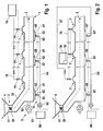
- a pneumatic conveying device In the embodiment of FIG. 1, a pneumatic conveying device is shown. It consists of an elongated conveying tube 1, which defines a conveying path 2. At the beginning of the conveyor pipe 1, a feed point 3 for the bulk material 4 to be transported is arranged. It comprises a funnel-shaped container 31, at the lower tip end of which a feed line 32 leads obliquely down to the beginning of the conveyor tube 1. By means of this bulk material feeding device 3, the bulk material 4 to be transported is introduced via a pressure lock 30 into the conveying tube 3 of the conveying device.
- a feed device 5 is arranged for conveying gas. It comprises a fan 51, which sucks gas in a manner not shown, and blows it over a short supply line 52 at the beginning of the conveying tube 1. Appropriately, the blowing takes place in parallel and possibly coaxial with the conveying path. 2
- the delivery pipe 1 which is shown only in sections, further comprises a fluidization device 6. It comprises a plurality of fluidizing segments 60 arranged along the conveying path 2 at the bottom of the conveying tube 1.
- the segments have a cavity 61, which is connected to the interior of the conveying tube 1 via a gas-permeable membrane. Fluidizing gas is supplied via a port 62 into the cavity 61.
- the connection 62 comprises a flow regulating valve 63.
- a fluidizing gas blower 65 which supplies the fluidizing gas to the connections 62 via a distributor line 64, is provided for supplying the fluidizing gas.
- a control device 66 cooperating with the flow control valves 63 is provided.
- a plurality of removal points 7 are arranged distributed over the length of the conveying pipe 1 according to the invention. In the illustrated embodiment, they have a distance from one another, which corresponds approximately to one hundred times the pipe diameter of the conveyor tube 1.
- the removal point 7 essentially comprises a trough-like trough 70 which is connected to the interior of the delivery tube 1 via a gas-permeable separating element 71.
- the separating element 71 may be designed in one or more layers. In the illustrated embodiment, it comprises a fabric 72 for separating the gas to be removed from the bulk material 4, which is to remain within the conveying tube 1. To support the fabric 72 and for better protection against mechanical wear, a perforated plate 73 is additionally provided for reinforcement.
- the fabric 72 and the perforated plate 73 are sized to span the entire width of the trough 70 and are gas-tight by clamping between a flange 75 of the trough and the outside of the conveyor tube 1 by means of a suitable screw connection (not shown). It is understood that the conveyor pipe 1 optionally has a correspondingly prepared recording for better conditioning and sealing of the trough 70.
- the ceiling of the trough 70 is connected to a discharge line 76. It comprises a control valve 77, which leads to a collecting line 78.
- a control device 79 which acts on the control valves 77 of the individual sampling points 7. This makes it possible to centrally control the amount of gas to be taken for the individual sampling points 7.
- a decentralized adjustment to the individual control valves 77 is provided alternatively or optionally also in addition.
- an optional flushing device 8 is provided at the removal points 7. It comprises a supply line 80 for purge gas with a first shut-off valve 81 and a second shut-off valve 74 in the line 76.
- the supply line 80 opens at the supply line 76 between the second shut-off valve 74 and the removal point 7.
- the first shut-off valve 81 is closed and the second shut-off valve 74 is opened.
- the corresponding flushing device 8 is actuated by the first shut-off valve 81 is opened and the second shut-off valve 74 is closed.
- Purging gas then flows through the conduit 80, the first shut-off valve 81 and the conduit 76 into the withdrawal point 7, whereby the tissue 72 is cleaned of impurities. This prevents a creeping blockage or blockage of the tissue 72 and thus the removal point 7 in the context of normal operation.
- the rinsing device 8 is expediently controlled by a rinsing control device (not shown).
- the second embodiment shown in FIG. 2 is identical in its basic features to the first embodiment shown in FIG. Matching components carry the same reference numbers. An explanation of their structure and operation is therefore omitted.
- the main difference between the two embodiments is that some of the extraction points (symbolized by the leftmost in FIG. 2) are not connected to the manifold 78, but via a cross feed line 67 to the supply port 62 downstream in the direction of the conveying path 2 located fluidization segment (here symbolized by the fluidization segment 60 ') is connected.
- This construction uses the gas taken off at the removal point 7 'to supply it via the cross-feed line 67 to the fluidization point 60' as fluidizing gas.
- the fluidization segment 60 ' is selected such that the pressure of the fluidizing gas required there for fluidization is at most as high as the pressure of the gas withdrawn at the removal point 7'.
- the supply of separate Fluidisiergas to the Fluidmaschinessegment 60 ' is dispensable. It therefore does not need to be extra provided by the fluidizing fan 65.
- the operating cost of the conveyor is reduced thereby.
- the remaining removal points 7 are obtained as in the first embodiment shown in FIG. 1 and connected to the common manifold 78.
- the same applies to other fluidizing segments 60 which, as explained above in connection with FIG. 1, are connected to the fluidizing gas line 64.
- the transverse feed line does not change the fact that the removal points 7, 7 'from the control device 79 are driven.
- this has an additional module 79 ', which controls the amount of gas taken off at the removal point 7' and its feed into the transverse feed line 67 for supplying the fluidizing segment 60 '.
- the fluidizing gas supplyable variable ports 62 are connected to the fluidizing control device 66.
- the additional control module 79 ' may be further configured to synchronize with the fluidization control module 66.
- a (not shown) signal line can be provided. This can ensure that so much gas is always withdrawn at the removal point 7 'that at least the quantity required to operate the fluidization segment 60' is provided at the supply connection 62 '.
Priority Applications (7)
| Application Number | Priority Date | Filing Date | Title |
|---|---|---|---|
| EP06018220A EP1894865A1 (fr) | 2006-08-31 | 2006-08-31 | Conveyeur pour produits pulvérulents |
| PCT/EP2007/007638 WO2008025568A1 (fr) | 2006-08-31 | 2007-08-31 | Dispositif de transport de matière pulvérulente |
| EP07802055.9A EP2061712B2 (fr) | 2006-08-31 | 2007-08-31 | Dispositif de transport de matière pulvérulente |
| US12/439,461 US20090269149A1 (en) | 2006-08-31 | 2007-08-31 | Conveyor device for powder materials |
| DE502007002369T DE502007002369D1 (de) | 2006-08-31 | 2007-08-31 | Fördervorrichtung für pulverförmiges gut |
| CN2007800320050A CN101511712B (zh) | 2006-08-31 | 2007-08-31 | 用于粉状物料的输送装置 |
| EA200900207A EA014359B1 (ru) | 2006-08-31 | 2007-08-31 | Устройство для транспортировки порошковых материалов |
Applications Claiming Priority (1)
| Application Number | Priority Date | Filing Date | Title |
|---|---|---|---|
| EP06018220A EP1894865A1 (fr) | 2006-08-31 | 2006-08-31 | Conveyeur pour produits pulvérulents |
Publications (1)
| Publication Number | Publication Date |
|---|---|
| EP1894865A1 true EP1894865A1 (fr) | 2008-03-05 |
Family
ID=37547768
Family Applications (2)
| Application Number | Title | Priority Date | Filing Date |
|---|---|---|---|
| EP06018220A Withdrawn EP1894865A1 (fr) | 2006-08-31 | 2006-08-31 | Conveyeur pour produits pulvérulents |
| EP07802055.9A Not-in-force EP2061712B2 (fr) | 2006-08-31 | 2007-08-31 | Dispositif de transport de matière pulvérulente |
Family Applications After (1)
| Application Number | Title | Priority Date | Filing Date |
|---|---|---|---|
| EP07802055.9A Not-in-force EP2061712B2 (fr) | 2006-08-31 | 2007-08-31 | Dispositif de transport de matière pulvérulente |
Country Status (6)
| Country | Link |
|---|---|
| US (1) | US20090269149A1 (fr) |
| EP (2) | EP1894865A1 (fr) |
| CN (1) | CN101511712B (fr) |
| DE (1) | DE502007002369D1 (fr) |
| EA (1) | EA014359B1 (fr) |
| WO (1) | WO2008025568A1 (fr) |
Cited By (1)
| Publication number | Priority date | Publication date | Assignee | Title |
|---|---|---|---|---|
| CN113184541A (zh) * | 2021-05-19 | 2021-07-30 | 芜湖市金贸环保材料科技有限公司 | 一种方便清洗的粉末涂料气力输送装置 |
Families Citing this family (14)
| Publication number | Priority date | Publication date | Assignee | Title |
|---|---|---|---|---|
| RU2476364C1 (ru) * | 2011-08-10 | 2013-02-27 | Федеральное государственное бюджетное образовательное учреждение высшего профессионального образования "Санкт-Петербургский государственный горный университет" | Нагнетательная пневмотранспортная установка |
| CN104487075A (zh) | 2012-02-29 | 2015-04-01 | 普马特里克斯公司 | 可吸入干粉剂 |
| JP5868839B2 (ja) * | 2012-12-27 | 2016-02-24 | 三菱重工業株式会社 | チャー払出管 |
| EP3129153B1 (fr) | 2014-04-07 | 2018-06-06 | Nordson Corporation | Centrale de distribution pour un system de poudre en phase dense |
| CN104003199A (zh) * | 2014-06-05 | 2014-08-27 | 上海天一高德机电实业有限公司 | 阀门式多级物料分配装置 |
| JP6109796B2 (ja) * | 2014-09-16 | 2017-04-05 | 三菱日立パワーシステムズ株式会社 | 粉体搬送装置及びチャー回収装置 |
| CN107224869A (zh) * | 2017-06-28 | 2017-10-03 | 中冶华天工程技术有限公司 | 一种多点受料均匀布料装置 |
| US10968054B2 (en) * | 2017-08-31 | 2021-04-06 | Kimberly-Clark Worldwide, Inc. | Air assisted particulate delivery system |
| WO2019157258A1 (fr) * | 2018-02-08 | 2019-08-15 | Invista North America S.A R.L. | Transbordement de solides |
| JP6885373B2 (ja) * | 2018-06-14 | 2021-06-16 | 井関農機株式会社 | 精米設備 |
| TWI675154B (zh) * | 2018-09-03 | 2019-10-21 | 江德明 | 壓差傳輸設備 |
| WO2020201015A1 (fr) * | 2019-04-04 | 2020-10-08 | Reel Alesa Ag | Dispositif d'alimentation à flux de précision |
| CN110745556A (zh) * | 2019-11-22 | 2020-02-04 | 中国矿业大学 | 一种气动输送混凝土砂浆的振动防堵装置及方法 |
| CN113120621A (zh) * | 2021-04-19 | 2021-07-16 | 沙洲职业工学院 | 一种建筑粉料防堵气力输送装置 |
Citations (4)
| Publication number | Priority date | Publication date | Assignee | Title |
|---|---|---|---|---|
| DE1150320B (de) * | 1957-09-11 | 1963-06-12 | Peters Ag Claudius | Pneumatische Foerderrinne fuer staubfoermige und feinkoernige Gueter |
| US3871711A (en) * | 1972-10-25 | 1975-03-18 | Otto Rusterholz | Method and apparatus for pneumatically conveying discrete amounts of particulate material |
| US6382881B1 (en) * | 1998-05-11 | 2002-05-07 | Aluminium Pechiney | Process for conveyance of powder materials in a hyperdense bed and potential fluidization device for embodiment of this process |
| US20020187012A1 (en) * | 2001-06-06 | 2002-12-12 | Herbert Grasshoff | Method and apparatus for the pneumatic conveying of fine bulk material |
Family Cites Families (11)
| Publication number | Priority date | Publication date | Assignee | Title |
|---|---|---|---|---|
| GB840984A (en) † | 1956-06-25 | 1960-07-13 | Frantisek Tikal | A method of transport of bulk material through a pipe line |
| HU188497B (en) † | 1983-10-06 | 1986-04-28 | Eroemue Es Halazattervezoe Vallalat,Hu | Duct for blower-type delivering materials of dust respectively granular structure |
| DE3714923A1 (de) * | 1987-05-05 | 1988-12-01 | Waeschle Maschf Gmbh | Vorrichtung zum pneumatischen foerdern von schuettgut |
| US4900200A (en) * | 1988-06-22 | 1990-02-13 | Matsui Manufacturing Co., Ltd. | Method for transporting powdered or granular materials by pneumatic force with a transport pipe of smaller diameter relative to particale size |
| US5252007A (en) † | 1992-05-04 | 1993-10-12 | University Of Pittsburgh Of The Commonwealth System Of Higher Education | Apparatus for facilitating solids transport in a pneumatic conveying line and associated method |
| DE4328626A1 (de) * | 1993-08-27 | 1995-03-02 | Motan Verfahrenstechnik | Verfahren zum Betrieb einer Förderleitung mit Dichtstromförderung und Vorrichtung zur Ausübung des Verfahrens |
| US5584612A (en) * | 1994-11-02 | 1996-12-17 | Nol-Tec Systems, Inc. | Apparatus and process for pneumatically conveying material and for controlling the feed of supplemental gas |
| DE10039564B4 (de) * | 2000-08-12 | 2009-11-05 | Mann + Hummel Protec Gmbh | Vorrichtung zum Fördern von Schüttgut |
| EP1295822A1 (fr) * | 2001-09-21 | 2003-03-26 | BMH Claudius Peters GmbH | Procédé et dispositif de transport pneumatique |
| DE10238946A1 (de) * | 2002-08-24 | 2004-03-04 | Mann + Hummel Protec Gmbh | Fördervorrichtung für schüttfähiges Gut |
| DE102004026119A1 (de) * | 2004-05-15 | 2005-12-08 | Lanxess Deutschland Gmbh | Verfahren zur pneumatischen Förderung von Glasfasern |
-
2006
- 2006-08-31 EP EP06018220A patent/EP1894865A1/fr not_active Withdrawn
-
2007
- 2007-08-31 DE DE502007002369T patent/DE502007002369D1/de active Active
- 2007-08-31 EP EP07802055.9A patent/EP2061712B2/fr not_active Not-in-force
- 2007-08-31 CN CN2007800320050A patent/CN101511712B/zh not_active Expired - Fee Related
- 2007-08-31 EA EA200900207A patent/EA014359B1/ru not_active IP Right Cessation
- 2007-08-31 US US12/439,461 patent/US20090269149A1/en not_active Abandoned
- 2007-08-31 WO PCT/EP2007/007638 patent/WO2008025568A1/fr active Application Filing
Patent Citations (4)
| Publication number | Priority date | Publication date | Assignee | Title |
|---|---|---|---|---|
| DE1150320B (de) * | 1957-09-11 | 1963-06-12 | Peters Ag Claudius | Pneumatische Foerderrinne fuer staubfoermige und feinkoernige Gueter |
| US3871711A (en) * | 1972-10-25 | 1975-03-18 | Otto Rusterholz | Method and apparatus for pneumatically conveying discrete amounts of particulate material |
| US6382881B1 (en) * | 1998-05-11 | 2002-05-07 | Aluminium Pechiney | Process for conveyance of powder materials in a hyperdense bed and potential fluidization device for embodiment of this process |
| US20020187012A1 (en) * | 2001-06-06 | 2002-12-12 | Herbert Grasshoff | Method and apparatus for the pneumatic conveying of fine bulk material |
Cited By (1)
| Publication number | Priority date | Publication date | Assignee | Title |
|---|---|---|---|---|
| CN113184541A (zh) * | 2021-05-19 | 2021-07-30 | 芜湖市金贸环保材料科技有限公司 | 一种方便清洗的粉末涂料气力输送装置 |
Also Published As
| Publication number | Publication date |
|---|---|
| EP2061712A1 (fr) | 2009-05-27 |
| EA200900207A1 (ru) | 2009-06-30 |
| EP2061712B1 (fr) | 2009-12-16 |
| EA014359B1 (ru) | 2010-10-29 |
| CN101511712A (zh) | 2009-08-19 |
| US20090269149A1 (en) | 2009-10-29 |
| CN101511712B (zh) | 2012-11-28 |
| WO2008025568A1 (fr) | 2008-03-06 |
| DE502007002369D1 (de) | 2010-01-28 |
| EP2061712B2 (fr) | 2014-01-01 |
Similar Documents
| Publication | Publication Date | Title |
|---|---|---|
| EP2061712B2 (fr) | Dispositif de transport de matière pulvérulente | |
| AT516916B1 (de) | Dosieranlage für eine Sandungsanlage eines Schienenfahrzeugs | |
| WO2003026991A1 (fr) | Dispositif et procede de transport pneumatique | |
| DE1949173B2 (de) | Verfahren und vorrichtung zur foerderung kohaesiven teilchenmaterials | |
| DE1556561B2 (de) | Pneumatische druckfoerdereinrichtung | |
| EP1730059B1 (fr) | Dispositif et procede pour le transport pneumatique de matieres en vrac finement divisees | |
| EP3768563B1 (fr) | Dispositif d'épandage de granulés | |
| DE2628811A1 (de) | Pneumatische foerderanlage fuer pulverfoermige und koernige gueter | |
| WO1982000132A1 (fr) | Procede et dispositif pour transporter pneumatiquement une matiere | |
| EP3415017B1 (fr) | Dispositif et procédé de collecte et d'évacuation des particules libres apparaissant lors de l'acheminement d'articles en forme de tige de l'industrie de traitement du tabac | |
| EP1637824B1 (fr) | Refroidisseur de matériau granulaire | |
| EP0164436B1 (fr) | Installation de transport dosé de matières pulvérulentes | |
| EP3108732B1 (fr) | Dispositif pour transporter granulaire sur une surface agricole avec pression de refoulement réduite | |
| EP3400371B1 (fr) | Tunnelier et système d'évacuation par voie hydraulique de déblais de forage et système pour établir une pression stable d'un liquide de forage dans la zone d'une roue de coupe dudit tunnelier | |
| AT506149B1 (de) | Fördervorrichtung für kleinteile | |
| EP2977340A1 (fr) | Station d'alimentation | |
| DE102010023322B4 (de) | Vorrichtung zum Vereinzeln von Teilen | |
| DE2363505A1 (de) | Aufgabevorrichtung einer druckluftfoerderanlage fuer schuettgut | |
| EP3691950B1 (fr) | Dispositif d'écoulement et procédé de commande et/ou de réglage d'une contrepression dans un dispositif pneumatique de transport de sable pour un véhicule ferroviaire et dispositif de transport de sable doté d'un dispositif d'écoulement | |
| EP3181497B1 (fr) | Unite de deviation pour transporteur pneumatique | |
| DE10349871B4 (de) | Verfahren und Einrichtung zur Versorgung von mehreren pneumatischen Förder-Anlagen mit Fördergas unter Druck | |
| EP3366450A1 (fr) | Fabrication additive avec transport pneumatique de produit en vrac en utilisant surpression | |
| EP1429982B1 (fr) | Dispositif de transport pneumatique | |
| DE102004055799B3 (de) | Verfahren zur Herstellung von Minen | |
| EP1279631B1 (fr) | Distribution de boues sur un matériau composite en movement |
Legal Events
| Date | Code | Title | Description |
|---|---|---|---|
| PUAI | Public reference made under article 153(3) epc to a published international application that has entered the european phase |
Free format text: ORIGINAL CODE: 0009012 |
|
| GRAP | Despatch of communication of intention to grant a patent |
Free format text: ORIGINAL CODE: EPIDOSNIGR1 |
|
| 17P | Request for examination filed |
Effective date: 20070808 |
|
| AK | Designated contracting states |
Kind code of ref document: A1 Designated state(s): AT BE BG CH CY CZ DE DK EE ES FI FR GB GR HU IE IS IT LI LT LU LV MC NL PL PT RO SE SI SK TR |
|
| AX | Request for extension of the european patent |
Extension state: AL BA HR MK YU |
|
| STAA | Information on the status of an ep patent application or granted ep patent |
Free format text: STATUS: THE APPLICATION HAS BEEN WITHDRAWN |
|
| 18W | Application withdrawn |
Effective date: 20080717 |