EP1894806A1 - Lokomotive mit Druckluftbeschaffungsanlage - Google Patents
Lokomotive mit Druckluftbeschaffungsanlage Download PDFInfo
- Publication number
- EP1894806A1 EP1894806A1 EP06018372A EP06018372A EP1894806A1 EP 1894806 A1 EP1894806 A1 EP 1894806A1 EP 06018372 A EP06018372 A EP 06018372A EP 06018372 A EP06018372 A EP 06018372A EP 1894806 A1 EP1894806 A1 EP 1894806A1
- Authority
- EP
- European Patent Office
- Prior art keywords
- compressed air
- locomotive
- air
- compressor
- underfloor
- Prior art date
- Legal status (The legal status is an assumption and is not a legal conclusion. Google has not performed a legal analysis and makes no representation as to the accuracy of the status listed.)
- Withdrawn
Links
- 230000003137 locomotive effect Effects 0.000 title claims abstract description 48
- 238000007605 air drying Methods 0.000 claims abstract description 17
- 238000001035 drying Methods 0.000 claims abstract description 3
- 238000009434 installation Methods 0.000 claims 1
- 241000196324 Embryophyta Species 0.000 description 6
- 239000002828 fuel tank Substances 0.000 description 5
- 238000001816 cooling Methods 0.000 description 4
- XLYOFNOQVPJJNP-UHFFFAOYSA-N water Substances O XLYOFNOQVPJJNP-UHFFFAOYSA-N 0.000 description 4
- 239000003795 chemical substances by application Substances 0.000 description 3
- 230000000712 assembly Effects 0.000 description 2
- 238000000429 assembly Methods 0.000 description 2
- 239000000314 lubricant Substances 0.000 description 2
- 239000002184 metal Substances 0.000 description 2
- 244000035744 Hura crepitans Species 0.000 description 1
- 230000003750 conditioning effect Effects 0.000 description 1
- 238000010276 construction Methods 0.000 description 1
- 239000007788 liquid Substances 0.000 description 1
- 238000005461 lubrication Methods 0.000 description 1
- 238000004519 manufacturing process Methods 0.000 description 1
- 239000004576 sand Substances 0.000 description 1
Images

Classifications
-
- B—PERFORMING OPERATIONS; TRANSPORTING
- B61—RAILWAYS
- B61C—LOCOMOTIVES; MOTOR RAILCARS
- B61C17/00—Arrangement or disposition of parts; Details or accessories not otherwise provided for; Use of control gear and control systems
Definitions
- the invention relates to a locomotive with a compressed air procurement system, which feeds in particular a compressed air-operated brake system, wherein the compressed air procurement system has a compressor for generating the compressed air and an air drying system for drying the compressed air.
- a locomotive is also understood to mean a power car for a rail vehicle train.
- "locomotive" in the context of the present application is limited to a traction unit or a power car for heavy rail vehicles and trains, especially on long-distance and regional trains, and therefore excludes light rail vehicles such as trams and subways of local transport.
- the requirements for such light rail vehicles are different from the requirements of locomotives and lead to other arrangements of the power units and auxiliary operations to which the compressed air procurement system belongs.
- a feature of a locomotive is a machine room in which the one or more drive units and auxiliary operations are arranged.
- the interior of the locomotive is required for technical facilities, there is no space for passengers or cargo available.
- the locomotive Under a locomotive is therefore understood in particular such a rail traction vehicle, the locomotive can be coupled to wagons and / or other locomotives.
- compressed air is used to power various systems, particularly the brake system of the entire locomotive-powered train.
- the compressed air procurement system is therefore usually (directly or eg indirectly via a compressed air tank) connected via controls to the main air line of the brake system and other systems, such.
- B. to the sand spreader, the wheel flange lubrication system, the air horns or Stromab chorushub issued by the sand spreader, the wheel flange lubrication system, the air horns or Stromab chorushub.
- the compressed air procurement system was locomotives in the engine room arranged because underfloor too little space is available and the engine room offers space.
- the invention is based on the finding that even with larger dimensions of the individual components (in particular compressor and air drying system) of the compressed air procurement system, as they occur in light rail vehicles, an arrangement of the compressed air procurement plant underfloor is possible.
- the dimensions of the individual components are larger in locomotives, since a higher air flow rate must be achieved, for example, in the order of 2,500 liters (uncompressed air) per minute.
- a condensate separator eg type KAB 23-25 of Knorr-Bremse AG, Moosacher Str 80, D-80809 Kunststoff, Germany
- Air drying plant eg, type LTZ015.2-H Knorr-Bremse AG
- the condensate is connected via a screw compact (ie to a common structural unit) connected to the air dryer.
- the condensate has the task to separate the pure liquid water content of the compressed and cooled air and to bring out of the compressed air system, while the (in Flow direction) downstream air drying plant serves to extract the compressed water and remove the gaseous water.
- the compressor, the air drying system and optionally arranged separately from the air dryer condensate or integrated into the air dryer condensate are pre-assembled as a structural unit, so that the preassembled unit can be demounted in a mounting step underfloor.
- the components of this unit are mechanically held together by a common support frame.
- the support frame is preferably attached to a side member (optionally or additionally to a cross member) of the locomotive box.
- the side member defines the bottom of the locomotive. Therefore, the arrangement is underfloor.
- the invention is further based on the finding that an arrangement of the compressed air procurement plant underfloor even has advantages over an arrangement in the engine room: If the arrangement succeeds underground, line lengths of the compressed air line can be shortened. This is especially true when (as in a preferred embodiment of the invention), the main air tank of the brake system are arranged at least partially underfloor. In addition, space can be saved within the engine room. This makes it possible to build the locomotive shorter. In addition, the final assembly of the compressed air procurement system is facilitated because it can be mounted from the outside and therefore the place provided for the assembly is more easily accessible.
- Another advantage relates to a feature of another preferred embodiment of the invention, namely the use of a lubricant-free (ie the movement of the moving parts is not lubricated with lubricant) compressor (in particular oil-free compressor, type W270-T Knorr-Bremse AG).
- a lubricant-free compressor in particular oil-free compressor, type W270-T Knorr-Bremse AG.
- the condensate which consists essentially of water
- the condensate can be drained directly from the condensate and / or the air dryer without any drain line.
- Yet another advantage of the arrangement underfloor is that the compressor can be cooled during the journey of the locomotive due to the cooling by wind better and / or with less effort than in the engine room.
- This is an additional advantage over light rail transport, as higher speeds are achieved in heavy rail traffic, resulting in the required braking power (the brake system is indeed fed by compressed air, therefore, this also means additional requirements for compressed air procurement) on the one hand but also the cooling performance On the other hand, the wind increases.
- the cooling load in the engine room is lower because the compressor is outside the engine room.
- the engine room cooling can therefore be designed for lower power.
- a soundproofing device is arranged transversely to the direction of travel of the locomotive on the outside of the compressor, in particular a soundproofing apron.
- a soundproofing apron has, in particular, a metal sheet whose surface normal is aligned with the compressor. The sheet may be angled at one or more edges or have an angled extending extension, so that a concave, the compressor at a distance on one side surrounding soundproofing shield is formed.
- a sound-insulating mat is arranged on the sound-absorbing apron (eg on the inside, i.e. on the side of the compressor), in particular glued to the sheet metal.
- the compressed air procurement system regardless of whether the locomotive is a diesel-electric driven (DE) or a purely electrically driven (E) locomotive, executed in the same way and arranged at the same place below ground.
- the structural unit described above can be pre-assembled and optionally arranged on a DE locomotive or an electric locomotive.
- a fuel tank is arranged at the same place in the underfloor area of the locomotive in the case of a DE locomotive and arranged in the case of an electric locomotive, a transformer for electrical connection to an electrical power grid , Underfloor remains in each case at the same place before a free space and / or behind the fuel tank or transformer in which the compressed air procurement plant is arranged.
- underfloor space is thus always available (in the longitudinal direction, that is to say in the direction of travel) in front of and behind the fuel tank or transformer.
- Each of these spaces are associated with fastening means on the supporting structure of the locomotive box, so that in each of the two spaces two different facilities can be arranged underfloor and fixed to the supporting structure.
- the compressed air procurement system (as a device) is arranged in one of the two free spaces and next to it (as a second device) in the same free space a compressed air tank is arranged, which is fed from the compressed air procurement system.
- Underground in this specification is understood to mean that the respective components are located below a floor of the locomotive and, in particular, are accessible from underneath the locomotive, but covers and other components may make access difficult.
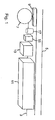
- Fig. 1 shows schematically a part of the underfloor area of a locomotive.
- the view shows individual assemblies and components of the locomotive, which are arranged below ground, from diagonally below.
- the illustration is not to scale, and other components (eg, compressed air piping) and parts (eg, the support frame of the compressed air supply system) are omitted for the sake of clarity.
- a longitudinal member 5 can be seen at the top of the picture.
- a wheel 7 and a part of the bogie 9 are shown.
- the lower edge of another longitudinal member 3 is seen.
- the side members 3, 5 delimit the underfloor area of the locomotive in which there is space for the arrangement of parts, components and assemblies, e.g. may be attached to the underbody, to one or both of the longitudinal members 3, 5 or to other fastening means in the underfloor area.
- the two side members may also be arranged closer to each other, so that laterally (transversely to the direction of travel) objects may also be arranged below the longitudinal members.
- a fuel tank 11 of a diesel-electric locomotive can be seen.
- a transformer may be arranged when the locomotive is a purely electrically powered locomotive.
- the fuel tank 11 and the bogie 9 There is space between the fuel tank 11 and the bogie 9 for the arrangement of the compressed air procurement system, where other facilities and objects can be arranged there, for example, a sandbox, a battery box or a compressed air tank.
- the compressed air tank which is designated there by the reference numeral 19.
- the compressed air supply system consists of the functional components compressor 13, air drying unit 15 and separate condensate separator 17.
- “Functional” refers to the generation and conditioning of compressed air.
- other components of the compressed air procurement system are present, namely in particular pipes and connections for the air flow and the support frame, which carries the functional components and the load-bearing Construction of the locomotive is attached. These non-functional components components are not shown in FIG. 1 for reasons of clarity.
- FIG. 2 shows a part of the line connections, namely a line connection between the compressor 13 and the separate condensate separator 17 and a line connection between the separate condensate separator 17 and the air drying system 15.
- a soundproofing skirt 21 can be seen, which can be attached to the longitudinal member 5 and extending from the longitudinal beam 5 down (out of the image plane). At its lower end, the soundproofing apron 21 may be angled and extend in the direction of the opposite longitudinal member 3. The bend is not apparent from Fig. 2.
- the line emerging from the air drying plant 15 is divided into two branches at a T-piece and leads firstly to the adjacent compressed air tank 19 (eg 400 l main air tank of the brake system) and leads to the other (As indicated by an arrow) through a bottom plate up into the arranged in the engine room of the locomotive compressed air frame (to operate other facilities of the compressed air and brake system).
- the adjacent compressed air tank 19 eg 400 l main air tank of the brake system
Landscapes
- Engineering & Computer Science (AREA)
- Automation & Control Theory (AREA)
- Transportation (AREA)
- Mechanical Engineering (AREA)
- Valves And Accessory Devices For Braking Systems (AREA)
Abstract
Die Erfindung betrifft eine Lokomotive mit einem Maschinenraum und mit einer Druckluftbeschaffungsanlage, die zumindest an eine Hauptluftleitung einer druckluftbetriebenen Bremsanlage angeschlossen ist, wobei die Druckluftbeschaffungsanlage einen Kompressor (13) zur Erzeugung der Druckluft und eine Lufttrocknungsanlage (15) zur Trocknung der Druckluft aufweist. Der Kompressor (13) und die Lufttrocknungsanlage (15) sind unterflur angeordnet.
Description
- Die Erfindung betrifft eine Lokomotive mit einer Druckluftbeschaffungsanlage, die insbesondere eine druckluftbetriebene Bremsanlage speist, wobei die Druckluftbeschaffungsanlage einen Kompressor zur Erzeugung der Druckluft und eine Lufttrocknungsanlage zur Trocknung der Druckluft aufweist.
- Unter einer Lokomotive wird auch ein Triebkopf für einen Schienenfahrzeug-Zugverband verstanden. "Lokomotive" im Sinne der hier vorliegenden Anmeldung ist jedoch auf ein Triebfahrzeug oder einen Triebkopf für schwere Schienenfahrzeuge und Zugverbände beschränkt, insbesondere auf Fern- und Regionalzüge, und schließt daher leichte Schienenfahrzeuge wie Straßenbahnen und Untergrundbahnen des Nahverkehrs aus. Die Anforderungen an solche leichten Schienenfahrzeuge sind von den Anforderungen an Lokomotiven verschieden und führen zu anderen Anordnungen der Antriebsaggregate und Hilfsbetriebe, zu denen die Druckluftbeschaffungsanlage gehört.
- Ein Merkmal einer Lokomotive ist ein Maschinenraum, in dem das oder die Antriebsaggregate und Hilfsbetriebe angeordnet sind. Da somit der Innenraum der Lokomotive für technische Einrichtungen benötigt wird, steht kein Platz für Fahrgäste oder Transportgut zur Verfügung. Unter einer Lokomotive wird daher insbesondere ein derartiges Schienen-Triebfahrzeug verstanden, wobei die Lokomotive an Waggons und/oder andere Lokomotiven angekoppelt werden kann.
- In Lokomotiven wird Druckluft zur Versorgung verschiedener Systeme verwendet, insbesondere für das Bremssystem des gesamten von der Lokomotive angetriebenen Zugverbandes. Die Druckluftbeschaffungsanlage ist daher in der Regel (direkt oder z. B. indirekt über einen Druckluftbehälter) über Steuerelemente an die Hauptluftleitung der Bremsanlage sowie an weitere Systeme angeschlossen, z. B. an die Sandstreuanlage, die Spurkranzschmieranlage, die Drucklufthörner oder die Stromabnehmerhubeinrichtung.
- Es ist eine Aufgabe der vorliegenden Erfindung, eine Lokomotive mit einer Druckluftbeschaffungsanlage anzugeben, wobei der zur Verfügung stehende Bauraum möglichst gut genutzt werden soll.
- Es wird vorgeschlagen, den Kompressor und die Lufttrocknungsanlage unterflur anzuordnen. Vorzugsweise sind weitere Komponenten der Druckluftbeschaffungsanlage (z. B. ein separater Kondensatabscheider), auf die noch näher eingegangen wird, ebenfalls unterflur angeordnet.
- Während bei leichten Schienenfahrzeugen eine Anordnung von Komponenten der Druckluftbeschaffungsanlage unterflur teilweise sogar zwingend ist (z. B. bei Niederflurfahrzeugen), wurde die Druckluftbeschaffungsanlage bei Lokomotiven im Maschinenraum angeordnet, da unterflur zu wenig Bauraum zur Verfügung steht und der Maschinenraum Platz bietet.
- Der Erfindung liegt jedoch die Erkenntnis zugrunde, dass auch bei größeren Abmessungen der einzelnen Komponenten (insbesondere Kompressor und Lufttrocknungsanlage) der Druckluftbeschaffungsanlage, als sie bei leichten Schienenfahrzeugen vorkommen, eine Anordnung der Druckluftbeschaffungsanlage unterflur möglich ist. Die Abmessungen der einzelnen Komponenten sind bei Lokomotiven größer, da eine höhere Luft-Förderleistung erreicht werden muss, die beispielsweise in der Größenordnung von 2.500 Liter (unkomprimierte Luft) pro Minute liegt.
- Bei der bevorzugten Ausführungsform der Erfindung wird ein Kondensatabscheider (z. B. Typ KAB 23-25 der Knorr-Bremse AG, Moosacher Str. 80, D-80809 München, Deutschland) als separates Bauteil in geringem Abstand (und in Luftströmungsrichtung) vor der Lufttrocknungsanlage (z. B. Typ LTZ015.2-H der Knorr-Bremse AG) vorgesehen. Insbesondere ist der Kondensatabscheider über eine Verschraubung kompakt (d.h. zu einer gemeinsamen bautechnischen Einheit) mit der Lufttrocknungsanlage verbunden. Der Kondensatabscheider hat dabei die Aufgabe, den rein flüssigen Wasseranteil der komprimierten und abgekühlten Luft zu separieren und aus dem Druckluftsystem zu bringen, während die (in Strömungsrichtung) nachgeschaltete Lufttrocknungsanlage dazu dient, der Druckluft den gasförmigen Wasseranteil zu entziehen und auszuscheiden.
- Vorzugsweise werden der Kompressor, die Lufttrocknungsanlage und der optional separat von der Lufttrocknungsanlage angeordnete Kondensatabscheider oder in die Lufttrocknungsanlage integrierte Kondensatabscheider als bautechnische Einheit vormontiert, sodass die vormontierte Einheit in einem Montageschritt unterflur endmontiert werden kann. Insbesondere werden die Komponenten dieser Einheit über einen gemeinsamen Tragrahmen mechanisch zusammengehalten. Der Tragrahmen wird vorzugsweise an einem Längsträger (optional oder zusätzlich an einem Querträger) des Lokomotivenkastens befestigt. Der Längsträger definiert dabei den Boden der Lokomotive. Daher ist die Anordnung unterflur.
- Der Erfindung liegt ferner die Erkenntnis zugrunde, dass eine Anordnung der Druckluftbeschaffungsanlage unterflur sogar Vorteile gegenüber einer Anordnung im Maschinenraum hat: Wenn die Anordnung unterflur gelingt, können Leitungslängen der Druckluftleitung verkürzt werden. Dies gilt insbesondere dann, wenn (wie bei einer bevorzugten Ausgestaltung der Erfindung) die Hauptluftbehälter der Bremsanlage zumindest teilweise unterflur angeordnet sind. Außerdem kann Bauraum innerhalb des Maschinenraums gespart werden. Dies ermöglicht es, die Lokomotive kürzer zu bauen. Außerdem ist die Endmontage der Druckluftbeschaffungsanlage erleichtert, da sie von außen montiert werden kann und der für die Montage vorgesehene Ort daher leichter zugänglich ist.
- Ein weiterer Vorteil betrifft ein Merkmal einer weiteren bevorzugten Ausführungsform der Erfindung, nämlich die Verwendung eines schmiermittelfreien (d. h. die Bewegung der beweglichen Teile wird nicht mit Schmiermittel geschmiert) Kompressors (insbesondere ölfreien Kompressors, Typ W270-T der Knorr-Bremse AG). In diesem Fall kann das bei der Lufttrocknung erzeugte Kondensat (das im Wesentlichen aus Wasser besteht) ohne Schädigung der Umwelt ins Gleisbett abgelassen werden, da es keine Schmiermittel enthält. Eine Anordnung unterflur führt zu kürzeren Leitungswegen für die Ableitung des Kondensats. Insbesondere kann das Kondensat auch ohne jegliche Ablassleitung unmittelbar aus dem Kondensatabscheider und/oder der Lufttrocknungsanlage abgelassen werden.
- Noch ein weiterer Vorteil der Anordnung unterflur besteht darin, dass der Kompressor während der Fahrt der Lokomotive aufgrund der Kühlung durch Fahrtwind besser und/oder mit geringerem Aufwand gekühlt werden kann als im Maschinenraum. Dies ist gegenüber dem leichten Schienenverkehr ein zusätzlicher Vorteil, da bei dem schweren Schienenverkehr höhere Geschwindigkeiten erreicht werden, wodurch sich die benötigte Bremsleistung (die Bremsanlage wird ja durch Druckluft gespeist, daher bedeutet dies auch zusätzliche Anforderungen an die Druckluftbeschaffung) einerseits aber auch die Kühlleistung durch Fahrtwind andererseits erhöht.
- Auch ist die Kühlungslast im Maschinenraum niedriger, da sich der Kompressor außerhalb des Maschinenraums befindet. Die Maschinenraumkühlung kann daher für geringere Leistungen ausgelegt werden.
- Gemäß einer bevorzugten Ausführungsform der Erfindung ist quer zur Fahrtrichtung der Lokomotive außenseitig des Kompressors eine Schallschutzvorrichtung angeordnet, insbesondere eine Schallschutzschürze. Eine solche Schürze weist insbesondere ein Blech auf, dessen Oberflächennormale auf den Kompressor ausgerichtet ist. Das Blech kann an einem oder mehreren Rändern abgewinkelt sein oder einen abgewinkelt verlaufenden Fortsatz aufweisen, so dass eine konkave, den Kompressor in Abstand einseitig umgebende Schallschutz-Abschirmung gebildet ist. Vorzugsweise ist an der Schallschutzschürze (z. B. auf der Innenseite, d.h. auf der Seite des Kompressors) eine Schall-Dämmmatte angeordnet, insbesondere auf das Blech aufgeklebt.
- Vorzugsweise ist die Druckluftbeschaffungsanlage unabhängig davon, ob es sich bei der Lokomotive um eine dieselelektrisch angetriebene (DE-) oder um eine rein elektrisch angetriebene (E-) Lokomotive handelt, in derselben Weise ausgeführt und an der derselben Stelle unterflur angeordnet. Insbesondere kann die oben beschriebene bautechnische Einheit vormontiert werden und wahlweise an einer DE-Lokomotive oder einer E-Lokomotive angeordnet werden.
- Bei einem konkreten Konzept zur Serienfertigung von DE-Lokomotiven und E-Lokomotiven ist an derselben Stelle im Unterflur-Bereich der Lokomotive im Fall einer DE-Lokomotive ein Kraftstofftank angeordnet und im Fall einer E-Lokomotive ein Transformator zum elektrischen Anschluss an ein elektrisches Energieversorgungsnetz angeordnet. Dabei verbleibt unterflur jeweils an derselben Stelle ein Freiraum vor und/oder hinter dem Kraftstofftank bzw. Transformator, in dem die Druckluftbeschaffungsanlage angeordnet wird.
- Bei einer besonders bevorzugten Ausführungsform ist unterflur somit jeweils ein Freiraum (in Längsrichtung, d. h. in Fahrtrichtung) vor und hinter dem Kraftstofftank bzw. Transformator vorhanden. Jedem dieser Freiräume sind Befestigungsmittel an der tragenden Konstruktion des Lokomotivenkastens zugeordnet, sodass in jedem der beiden Freiräume zwei verschiedene Einrichtungen unterflur angeordnet und an der tragenden Konstruktion befestigt werden können. Bei der im Folgenden beschriebenen konkreten Ausführungsform ist in einem der beiden Freiräume die Druckluftbeschaffungsanlage (als eine Einrichtung) angeordnet und ist daneben (als zweite Einrichtung) in demselben Freiraum ein Druckluftbehälter angeordnet, der aus der Druckluftbeschaffungsanlage gespeist wird.
- Ein Ausführungsbeispiel der Erfindung wird nun unter Bezugnahme auf die beigefügte Zeichnung beschrieben. Die einzelnen Figuren der. Zeichnung zeigen:
- Fig. 1
- schematisch eine dreidimensionale Ansicht auf einen Unterflur-Bereich einer Lokomotive,
- Fig. 2
- eine schematische Ansicht von unten auf die in Fig. 1 dargestellte Anordnung.
- Unter "unterflur" wird in dieser Beschreibung verstanden, dass die jeweiligen Bauteile unterhalb eines Bodens der Lokomotive angeordnet sind und insbesondere von unterhalb der Lokomotive zugänglich sind, wobei jedoch Abdeckungen und andere Bauteile den Zugang erschweren können.
- Fig. 1 zeigt schematisch einen Teil des Unterflurbereichs einer Lokomotive. Die Ansicht zeigt einzelne Baugruppen und Komponenten der Lokomotive, die unterflur angeordnet sind, von schräg unten. Die Darstellung ist nicht maßstabsgerecht zu verstehen, und es sind weitere Komponenten (z. B. die Druckluftverrohrung) und Teile (z. B. der Tragrahmen der Druckluftbeschaffungsanlage) aus Gründen der Übersichtlichkeit weggelassen.
- Im Vordergrund, oben im Bild, ist ein Längsträger 5 erkennbar. Links im Bild sind ein Rad 7 und ein Teil des Drehgestells 9 dargestellt. Im Hintergrund sieht man die Unterkante eines weiteren Längsträgers 3. Betrachtet quer zur Fahrtrichtung begrenzen die Längsträger 3, 5 den Unterflurbereich der Lokomotive, in dem Raum für die Anordnung von Teilen, Komponenten und Baugruppen ist, die z.B. am Unterboden, an einem oder beiden der Längsträger 3, 5 oder an weiteren Befestigungsmitteln im Unterflurbereich befestigt sein können. In anderer Ausgestaltung können die beiden Längsträger jedoch auch näher beieinander angeordnet sein, sodass auch seitlich (quer zur Fahrtrichtung) über die Längsträger hinaus Gegenstände unterflur angeordnet sein können.
- Rechts in der Fig. 1 ist ein Kraftstofftank 11 einer dieselelektrisch angetriebenen Lokomotive erkennbar. Alternativ kann an dieser Stelle ein Transformator angeordnet sein, wenn es sich bei der Lokomotive um eine rein elektrisch angetriebene Lokomotive handelt. Zwischen dem Kraftstofftank 11 und dem Drehgestell 9 befindet sich Platz für die Anordnung der Druckluftbeschaffungsanlage, wobei dort auch andere Einrichtungen und Gegenstände angeordnet sein können, beispielsweise ein Sandkasten, ein Batteriekasten oder ein Druckluftbehälter. In der Darstellung von Fig. 2 erkennt man auch den Druckluftbehälter, der dort mit dem Bezugszeichen 19 bezeichnet ist.
- Die Druckluftbeschaffungsanlage besteht aus den funktionalen Komponenten Kompressor 13, Lufttrocknungsanlage 15 und separater Kondensatabscheider 17. "Funktional" bezieht sich auf die Erzeugung und Konditionierung der Druckluft. Darüber hinaus sind noch weitere Komponenten der Druckluftbeschaffungsanlage vorhanden, nämlich insbesondere Rohre und Anschlüsse für den Luftstrom sowie der Tragrahmen, der die funktionalen Komponenten trägt und an der tragenden Konstruktion der Lokomotive befestigt ist. Diese nicht funktionalen Komponenten Komponenten sind aus Gründen der Übersichtlichkeit in Fig. 1 nicht dargestellt. In Fig. 2 ist ein Teil der Leitungsverbindungen dargestellt, nämlich eine Leitungsverbindung zwischen dem Kompressor 13 und dem separaten Kondensatabscheider 17 und eine Leitungsverbindung zwischen dem separaten Kondensatabscheider 17 und der Lufttrocknungsanlage 15.
- Im oberen Teil der Fig. 2 ist außerdem eine Schallschutzschürze 21 erkennbar, die an dem Längsträger 5 befestigt sein kann und sich von dem Längsträger 5 nach unten (aus der Bildebene heraus) erstreckt. An ihrem unteren Ende kann die Schallschutzschürze 21 abgewinkelt sein und sich in Richtung des gegenüberliegenden Längsträgers 3 erstrecken. Die Abwinklung ist aus Fig. 2 nicht erkennbar.
- Die von der Lufttrocknungsanlage 15 ausgehende Leitung wird in dem konkreten Ausführungsbeispiel von Fig. 2 an einem T-Stück in zwei Zweige aufgeteilt und führt zum einen in den benachbarten Druckluftbehälter 19 (z. B. 400 1-Hauptluftbehälter der Bremsanlage) und führt zum anderen (wie durch einen Pfeil angedeutet) durch ein Bodenblech nach oben in das im Maschinenraum der Lokomotive angeordnete Druckluftgerüst (zum Betrieb weiterer Einrichtungen der Druckluft- und Bremsanlage).
Claims (5)
- Lokomotive mit einem Maschinenraum und mit einer Druckluftbeschaffungsanlage, die zumindest an eine Hauptluftleitung einer druckluftbetriebenen Bremsanlage angeschlossen ist, wobei die Druckluftbeschaffungsanlage einen Kompressor (13) zur Erzeugung der Druckluft und eine Lufttrocknungsanlage (15) zur Trocknung der Druckluft aufweist,
dadurch gekennzeichnet, dass
der Kompressor (13) und die "Lufttrocknungsanlage (15) unterflur angeordnet sind. - Lokomotive nach dem vorhergehenden Anspruch, wobei ein Kondensatabscheider (17) vorgesehen ist, der ein von der Lufttrocknungsanlage (15) separates Bauteil ist.
- Lokomotive nach einem der vorhergehenden Ansprüche, wobei der Kompressor (13) ein schmiermittelfreier Kompressor ist.
- Lokomotive nach einem der vorhergehenden Ansprüche, wobei der Kompressor (13), die Lufttrocknungsanlage (15) und ein optional separat von der Lufttrocknungsanlage (15) angeordneter Kondensatabscheider (17) oder ein in die Lufttrocknungsanlage integrierter Kondensatabscheider eine bautechnische Einheit bilden, die vor dem Einbau unterflur vormontiert wurde.
- Lokomotive nach einem der vorhergehenden Ansprüche, wobei quer zur Fahrtrichtung der Lokomotive außenseitig des Kompressors (13) eine Schallschutzvorrichtung (21) angeordnet ist.
Priority Applications (2)
| Application Number | Priority Date | Filing Date | Title |
|---|---|---|---|
| EP06018372A EP1894806A1 (de) | 2006-09-01 | 2006-09-01 | Lokomotive mit Druckluftbeschaffungsanlage |
| DE200620020397 DE202006020397U1 (de) | 2006-09-01 | 2006-09-01 | Lokomotive mit Druckluftbeschaffungsanlage |
Applications Claiming Priority (1)
| Application Number | Priority Date | Filing Date | Title |
|---|---|---|---|
| EP06018372A EP1894806A1 (de) | 2006-09-01 | 2006-09-01 | Lokomotive mit Druckluftbeschaffungsanlage |
Publications (1)
| Publication Number | Publication Date |
|---|---|
| EP1894806A1 true EP1894806A1 (de) | 2008-03-05 |
Family
ID=37718870
Family Applications (1)
| Application Number | Title | Priority Date | Filing Date |
|---|---|---|---|
| EP06018372A Withdrawn EP1894806A1 (de) | 2006-09-01 | 2006-09-01 | Lokomotive mit Druckluftbeschaffungsanlage |
Country Status (1)
| Country | Link |
|---|---|
| EP (1) | EP1894806A1 (de) |
Cited By (1)
| Publication number | Priority date | Publication date | Assignee | Title |
|---|---|---|---|---|
| CN115817543A (zh) * | 2022-11-28 | 2023-03-21 | 中车大连机车车辆有限公司 | 一种智能化城轨列车轮缘润滑系统控制方法及车辆 |
Citations (3)
| Publication number | Priority date | Publication date | Assignee | Title |
|---|---|---|---|---|
| US1787617A (en) * | 1929-05-27 | 1931-01-06 | Cincinnati Car Corp | Gasoline locomotive |
| DE2406271A1 (de) * | 1974-02-09 | 1975-08-21 | Uerdingen Ag Waggonfabrik | Vorrichtung zur anbringung von aggregaten, insbesondere von antriebs- und hilfsaggregaten, im untergestell von schienenfahrzeugen |
| FR2334525A1 (fr) * | 1975-12-12 | 1977-07-08 | Alsthom Cgee | Dispositif de refroidissement de semi-conducteurs appliques au materiel ferroviaire |
-
2006
- 2006-09-01 EP EP06018372A patent/EP1894806A1/de not_active Withdrawn
Patent Citations (3)
| Publication number | Priority date | Publication date | Assignee | Title |
|---|---|---|---|---|
| US1787617A (en) * | 1929-05-27 | 1931-01-06 | Cincinnati Car Corp | Gasoline locomotive |
| DE2406271A1 (de) * | 1974-02-09 | 1975-08-21 | Uerdingen Ag Waggonfabrik | Vorrichtung zur anbringung von aggregaten, insbesondere von antriebs- und hilfsaggregaten, im untergestell von schienenfahrzeugen |
| FR2334525A1 (fr) * | 1975-12-12 | 1977-07-08 | Alsthom Cgee | Dispositif de refroidissement de semi-conducteurs appliques au materiel ferroviaire |
Cited By (1)
| Publication number | Priority date | Publication date | Assignee | Title |
|---|---|---|---|---|
| CN115817543A (zh) * | 2022-11-28 | 2023-03-21 | 中车大连机车车辆有限公司 | 一种智能化城轨列车轮缘润滑系统控制方法及车辆 |
Similar Documents
| Publication | Publication Date | Title |
|---|---|---|
| EP1926648B1 (de) | Herstellung einer lokomotive | |
| EP2681094A1 (de) | Schienenfahrzeug mit aufnahmeraum unterhalb des bodens | |
| EP2236379B1 (de) | Mehrgliedriges Schienenfahrzeug | |
| EP0625456A1 (de) | Vorrichtung zum Belüften mindestens eines Fahrmotors und/oder einer Kühleinrichtung eines Schienentriebfahrzeuges und Schienentriebfahrzeug mit einer derartigen Vorrichtung | |
| DE202013012397U1 (de) | Vorrichtung zur Verzweigung von mehrgleisigen Bahnen | |
| WO2005032900A1 (de) | Vollautomatisches verkehrssystem | |
| EP3821094B1 (de) | Bahnhof, insbesondere tunnelbahnhof und verwendung einer filtereinheit in einem bahnhof | |
| DE202006020397U1 (de) | Lokomotive mit Druckluftbeschaffungsanlage | |
| EP0456000B1 (de) | Verkehrssystem für den städtischen Verkehr mit Zugseil und Schienensystem | |
| DE202014104247U1 (de) | Vorrichtung zur Energiegewinnung bei der Durchfahrt von Kraftfahrzeugen | |
| DE4419851A1 (de) | Schienengebundenes Transportsystem | |
| DE29922808U1 (de) | Sicherheitsvorrichtung für Schienenfahrzeuge | |
| EP2218623B1 (de) | Lokomotive mit zwei übereinander angeordneten Antriebseinheiten | |
| DE4012704A1 (de) | Mehrteiliges strassenfahrzeug, insbesondere fuer den personennahverkehr | |
| EP0536433A1 (de) | Mehrteiliges Strassenfahrzeug, insbesondere für den Personennahverkehr | |
| DE102016205215A1 (de) | Eisenbahn-Triebfahrzeug mit Dachübergangselement | |
| DE202019004346U1 (de) | Niederflurgelenkbeiwagen dessen Fahrzeugteile aus bereits genutzten Fahrzeugen (Niederflurgelenktriebwagen NGT6 DD und/oder NGT8 DD) neu zusammengestellt werden | |
| DE20002814U1 (de) | Doppelstöckiges Schienenfahrzeug | |
| DE102019203962A1 (de) | Schienenfahrzeug zur Personenbeförderung mit Wagenübergangsmodulen | |
| DE19547153C1 (de) | Verfahren und Schienenfahrzeug zum Rangieren in Rangierbahnhöfen mit Ablaufanlagen | |
| DE102014207489A1 (de) | Schienengebundenes Transportsystem | |
| DE19742279A1 (de) | Schienenfahrzeug | |
| EP1449736A1 (de) | Niedrig-Lokomotive | |
| CH709099B1 (de) | Wagenkasten, Zugkomposition mit Wagenkasten und Verfahren zur Herstellung eines Wagenkastens. | |
| DE102022108000A1 (de) | Einschienenfahrzeugsystem |
Legal Events
| Date | Code | Title | Description |
|---|---|---|---|
| PUAI | Public reference made under article 153(3) epc to a published international application that has entered the european phase |
Free format text: ORIGINAL CODE: 0009012 |
|
| AK | Designated contracting states |
Kind code of ref document: A1 Designated state(s): AT BE BG CH CY CZ DE DK EE ES FI FR GB GR HU IE IS IT LI LT LU LV MC NL PL PT RO SE SI SK TR |
|
| AX | Request for extension of the european patent |
Extension state: AL BA HR MK YU |
|
| AKX | Designation fees paid | ||
| STAA | Information on the status of an ep patent application or granted ep patent |
Free format text: STATUS: THE APPLICATION IS DEEMED TO BE WITHDRAWN |
|
| 18D | Application deemed to be withdrawn |
Effective date: 20080906 |
|
| REG | Reference to a national code |
Ref country code: DE Ref legal event code: 8566 |