EP1892479A2 - Appareil de cuisson - Google Patents
Appareil de cuisson Download PDFInfo
- Publication number
- EP1892479A2 EP1892479A2 EP07016370A EP07016370A EP1892479A2 EP 1892479 A2 EP1892479 A2 EP 1892479A2 EP 07016370 A EP07016370 A EP 07016370A EP 07016370 A EP07016370 A EP 07016370A EP 1892479 A2 EP1892479 A2 EP 1892479A2
- Authority
- EP
- European Patent Office
- Prior art keywords
- cooking appliance
- air
- ventilation
- appliance device
- cooking
- Prior art date
- Legal status (The legal status is an assumption and is not a legal conclusion. Google has not performed a legal analysis and makes no representation as to the accuracy of the status listed.)
- Withdrawn
Links
Images
Classifications
-
- F—MECHANICAL ENGINEERING; LIGHTING; HEATING; WEAPONS; BLASTING
- F24—HEATING; RANGES; VENTILATING
- F24C—DOMESTIC STOVES OR RANGES ; DETAILS OF DOMESTIC STOVES OR RANGES, OF GENERAL APPLICATION
- F24C15/00—Details
- F24C15/20—Removing cooking fumes
- F24C15/2007—Removing cooking fumes from oven cavities
Definitions
- the invention is based on a cooking device device according to the preamble of claim 1.
- a Garellavorraum comprising a ventilation unit for ventilation and / or ventilation of a cooking chamber.
- the ventilation unit has for this purpose at least one ventilation duct.
- the ventilation unit sucks air directly from a switch room, wherein the switch room is located above the ventilation duct.
- the object of the invention is in particular to provide a generic Garellavorraum with improved properties in terms of a structurally simple air intake.
- the object is achieved by the features of claim 1, while advantageous embodiments and modifications of the invention can be taken from the dependent claims.
- the invention relates to a Garellavorraum with a ventilation unit, which is provided for ventilation and / or ventilation of a cooking chamber and having at least one ventilation duct.
- the cooking device device has an intake opening which is provided for a suction of air from a region below the ventilation duct, whereby a simple air intake within the cooking appliance device can be realized.
- the ventilation duct of the cooking appliance device is preferably arranged above a baking oven muffle, so that air can be sucked in through the oven muffle already through the intake of air below the ventilation duct and thus less condensation can form within the ventilation unit, by the already preheated air for Removal of steam-containing air from the oven can be used.
- components of the ventilation unit can be advantageously protected against corrosion and thus increases their life and / or a failure of the components can be advantageously avoided.
- a "ventilation duct” should be understood to mean, in particular, a duct which, in contrast to a suction a targeted flow control function in a targeted direction.
- the term “below the ventilation duct” is intended to mean a region of the cooking appliance device which is arranged spatially below the ventilation duct, in particular in an operating position provided for operation of the cooking appliance device.
- a “cooking space” is to be understood as meaning a space which is bounded by a wall, for example the wall of a baking oven muffle, and in which, in particular, food and / or foodstuffs are heated for preparation, for example in a microwave, in an oven, etc ,
- the cooking appliance device has a switch room, which is arranged above the ventilation duct, whereby the switch room is shielded at least from a direct air intake by means of the ventilation unit, so that in this case components, in particular electrical and / or electronic components of the switch room, advantageously protected can be.
- a “switch room” should be understood in particular to mean a region of the cooking device device in which electrical and in particular electronic components are arranged, which are required for operation of the cooking appliance device. This is to be understood by "above the ventilation duct” an area of the cooking appliance device which is arranged spatially above the ventilation duct, in particular in an operating position provided for operation of the cooking appliance apparatus.
- the switch compartment is at least substantially closed relative to a region of the air intake, whereby an air exchange between the switch compartment and the region of the air intake can at least be reduced.
- an air exchange between the switch compartment and the region of the air intake can at least be reduced.
- the cooking device device has a closed cover, by means of which the switch room is separated from the ventilation duct, whereby a simple and cost-effective sealing of the switch room reaches from the ventilation duct can be.
- a simple and cost-effective sealing of the switch room reaches from the ventilation duct can be.
- steam-containing air from the cooking chamber passes through the ventilation channel in the switch room, so that a vapor condensation of electrical components within the switch room and a concomitant failure of the electrical components can be at least reduced.
- a "closed cover” is to be understood as meaning a cover which is closed, in particular with regard to an air exchange between at least two areas, such as a switch room and a ventilation duct.
- the cooking device device has a fan motor, which is arranged within the switch room, whereby a complex assembly of the fan motor can be avoided within the ventilation duct and thus additional installation costs and assembly costs can be saved, such as a laying of a electrical connection for the fan motor inside the ventilation duct.
- additional installation costs and assembly costs can be saved, such as a laying of a electrical connection for the fan motor inside the ventilation duct.
- the fan motor is arranged on the closed cover of the ventilation duct, whereby a particularly short drive path to a fan wheel driven by the fan motor can be achieved and a short drive shaft connected thereto can be used to drive the fan wheel.
- the cooking appliance device has an intermediate bottom, by means of which the ventilation duct is limited downwards, whereby a structurally simple separation of the ventilation duct from the area for the suction of air can be advantageously achieved.
- the intake of air can be limited to a region of the intake through the intermediate bottom, and thus an advantageous air flow in the ventilation duct can be achieved.
- “downwards” is to be understood as meaning a region of the cooking appliance device which is arranged at least partially below the ventilation channel in an operating position intended for operation of the cooking appliance device in the vertical direction.
- the intermediate bottom has a suction nozzle for the intake of air, whereby a suction speed of air can be advantageously increased and thus an undesirable dust deposition on components which are arranged below the suction opening, can be avoided.
- the suction nozzle may form a separate component or be particularly advantageously formed integrally with the intermediate bottom, as impressed, for example, in the intermediate floor, so that in this way further components, space, installation costs and costs can be saved.
- the suction nozzle comprises a protective means, whereby an advantageous protection of the fan can be achieved.
- the protective means is preferably designed as a grid, so that in an operation of the fan or the cooking appliance device, a maximum air flow through the nozzle can be ensured. Other components, space, installation costs and costs can be saved if the protective means is formed integrally with the nozzle.
- the intermediate bottom to a vent opening which is provided for escape of a vapor-containing air from the cooking chamber, which structurally simple, a steam-containing air of the cooking chamber can be sucked.
- the exhaust opening is disposed within the ventilation duct, so that a flow of air generated by the fan can transport the steam-containing air of the cooking chamber with to the outside.
- the hot steam-containing air of the cooking chamber by convection in the ventilation duct and be transported along the ventilation duct to the outside, which can be dispensed with an additional and expensive Lmonternachlauf, especially if the cooking appliance at least one Has deduction deflection, which is intended to divert the steam-containing air from the cooking chamber in the direction of an output flow.
- the ventilation duct extends horizontally outward below a switch room, whereby a simple escape of a steam-containing air can be achieved.
- the ventilation duct opens on a front side of the cooking appliance device, so that an undesirable formation of condensation water, such as on a rear side of the cooking appliance device, can be avoided.
- a Garellavorraum is proposed with a baking oven muffle, wherein the suction opening is provided for a suction of air from an adjacent to the baking oven muffle area.
- an air flow can advantageously be achieved at least partially around the baking oven muffle, which at least reduces and / or avoids the deposition of dust on further components arranged around the oven muffle, in particular on an oven lighting.
- the suction of air leaks of the baking oven muffle, such as by an oven light, radiator flanges, etc. on the baking oven muffle, sucked, and thus formation of condensate and / or deposition of fat vapor within a cooking appliance and / or an adjacent built-in furniture at least reduced and / or avoided.
- an advantageous heated by the baking oven muffle air can be sucked.
- a "baking oven muffle" is to be understood in particular as meaning a cooking chamber delimiting a unit with or without an insulating layer.
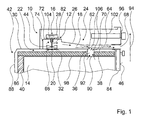
- FIG. 1 shows a section through a cooking appliance 42 with a cooking appliance device 10 according to the invention, which comprises a ventilation unit 12, and a baking oven muffle 40 with a cooking chamber 14.
- the ventilation unit 12 has a fan 16, which includes a fan 44 and a fan motor 28, and a ventilation duct 18 and is provided for ventilation and / or ventilation of the cooking chamber 14 of the cooking appliance 42.
- the cooking device device 10 has a switch room 24 with a switch unit 102, which is arranged in a normal operating position of the cooking device 10 or the cooking appliance 42 substantially above the ventilation channel 18.
- the ventilation duct 18 of the ventilation unit 12 is arranged between the oven muffle 40 of the cooking appliance 42 with an overlying area 22 for air intake and the switch room 24. Together with the switch room 24, the ventilation duct 18 is separated from the region 22 of an air intake and the oven muffle 40 by an intermediate bottom 30 in a normal operating position of the cooking appliance device 10 or the cooking appliance 42.
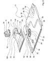
- the intermediate bottom 30 is integrally formed by a sheet metal part and thereby arranged perpendicular to a front side 46 of the cooking appliance 42.
- the intermediate bottom 30 forms a surface with two mutually parallel offset planes 48, 50 ( Figures 2 and 3).
- the plane 48 of the intermediate bottom 30, which is assigned to a region 52 of the ventilation duct 18, is offset parallel to the plane 50 of the intermediate bottom 30, which is assigned to a region 54 of the switch compartment 24, in a direction perpendicular to a main extension surface 56 of the intermediate bottom 30.
- the plane 48 in the region 52 of the ventilation duct 18 in a normal operating position of the cooking appliance 42 is arranged at a smaller distance from the baking oven muffle than the level 50 in the region 54 of the switch room 24.
- the intermediate bottom 30 forms a substantially closed cover of the switch compartment 24 in the region 54 of the region 22 of the air intake below the false bottom 30 in the direction of the oven muffle 40.
- the switch room 24 is arranged separately from the region 22 of the air intake, so that components of the switch room 24th , in particular the switch unit 102, are protected from a flow of air generated by the air intake and undesirable in the switch room 24.
- fastening elements 60 are formed perpendicular to the main extension surface 56 of the intermediate bottom 30 and are provided for fastening the intermediate bottom 30 to a wall of the cooking appliance 42, not shown in greater detail.
- the intermediate bottom 30 has an intake opening 20, which is provided for a suction of air from the region 22 below the ventilation channel 18 (FIGS. 1 and 2).
- the suction port 20 is circular in shape and disposed within a suction nozzle 32.
- the suction nozzle 32 is formed integrally with the intermediate bottom 30, is embossed in the intermediate bottom 30 and extends - starting from the plane 48 - against a flow direction during operation of the cooking device 10 in the direction of the oven muffle 40, so that the suction port 20 closer to the oven muffle 40 is arranged as the level 48 of the intermediate bottom 30.
- the suction port 20 and the suction nozzle 32 comprises an integrally formed on the intermediate bottom 30 protection means 34 which is formed like a lattice.
- the intermediate bottom 30 comprises a discharge opening 36, which is provided for a suction or a withdrawal of hot, steam-containing air from the cooking chamber 14 ( Figures 1 and 2).
- the outlet opening 36 is arranged within the ventilation channel 18 at a distance from the suction opening 20 along a main extension direction 38 of the ventilation channel 18 in the direction 64 of an outlet flow or in the direction of an outlet opening 68 (FIGS. 1 and 3).
- the discharge opening 36 is obliquely embossed to the main extension surface 56 in the intermediate bottom 30, so that two Abzugsumsch 62, 70 arise. ( Figure 2).
- the deduction deflecting means 62, 70 each have a deduction slope 106 which, with the main extension surface 56 of the intermediate bottom 30, encloses an acute angle facing the withdrawal opening 36.
- the Abzugsumsch 62, 70 are arranged in the main extension direction 38 on opposite sides of the exhaust opening 36, wherein the first Abzugsumlenkstoff 62 extends in the direction of the outlet opening 68 into the ventilation channel 18 and the second Abzugsumlenkstoff 70 in a direction of the fan 44 in the Area 22 extends below the intermediate bottom 30.
- the steam-containing air escaping from the cooking chamber 14 is deflected by means of the draw-deflection means 62, 70 in a direction 64 of an outlet flow within the ventilation channel 18 or in the direction of the outlet opening 68.
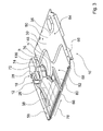
- the switch room 24 and the ventilation channel 18 are separated from one another by a closed cover 26 (FIG. 1), wherein the switch room 24 is substantially above in a normal operating position of the cooking appliance 42, at an area 22 for air intake remote from the outside of the ventilation duct 18 is arranged.
- the switch room 24 is separated with respect to an air exchange with the ventilation channel 18 and penetration of steam-containing air from the cooking chamber 14 via the ventilation channel 18 in the switch room 24 is avoided, so that components of the switch room 24 are protected from moisture from the cooking chamber 14.
- the closed cover 26 is formed in a region of the fan 16 is substantially circular and has a perpendicular to a substantially circular cover 72 aligned edge 74 ( Figures 1 to 3).
- the border 74 adjoins a side of the substantially circular cover 72 facing the intermediate bottom 30.
- a height h of the border 74 is adapted to the fan 44 of the ventilation unit 12, which is located below the substantially circular cover 72 and thus within the ventilation duct 12.
- the ventilation duct 18 extends in the manner of a fan-like manner toward the substantially circular cover 72 in the direction of the outlet opening 68.
- a height h 'of a border 76 of the fan-like ventilation duct 18 decreases, starting from the border 74, in the direction 64 of the outlet flow (FIGS. 1 to 3).
- the ventilation channel 18 has the main extension direction 38 along the direction 64 of the output flow.
- the closed cover 26 In the assembled state, the closed cover 26 together with the intermediate bottom 30 forms the outlet opening 68 which is located on the front side 46 of the cooking appliance 42 (FIG. 1).
- the ventilation duct 18 runs horizontally outward, so that the outlet opening 68 is arranged in the vertical direction 94 between a baking oven door 84 of the cooking appliance 42 and a control panel 96 of the cooking appliance 42 (FIG. 1).
- the closed cover 26 comprises a perpendicular to a main extension direction 78 of the outlet opening 68 and parallel to the main extension surface 56 of the intermediate floor 30 extending mounting rail 80, which is provided for attachment of the closed cover 26 to the intermediate bottom 30.
- the closed cover 26 has an additional fastening edge 100 for attachment to the intermediate bottom 30, which is arranged on a side of the borders 74, 76 facing the intermediate bottom 30 and rests on the intermediate bottom 30 in the mounted state of the cooking appliance device 10.
- the fan motor 28 of the ventilation unit 12 is located within the switch room 24 directly on the substantially circular cover 72 of the ventilation duct 18.
- the fan motor 28 is provided to drive the fan wheel 44 of the ventilation unit 12.
- the fan 44 is disposed between the suction nozzle 32 and the suction port 20 and the substantially circular cover 72 of the closed cover 26 within the ventilation channel 18.
- the fan motor 28 is connected to the fan wheel 44 via a drive shaft 82 (FIG. 1), by means of which a torque of the fan motor 28 is transmitted to the fan wheel 44 during operation of the cooking device device 10.
- the closed cover 26 has a recess 104, through which the drive shaft 82 engages sealed from the switch room 24 in the ventilation channel 18.
- the area 22 for the air intake of the ventilation unit 12 (FIG. 1) is located on a side of the intermediate bottom 30 facing away from the ventilation channel 18 or below the suction opening 20, the area 22 for the air intake of the ventilation unit 12 (FIG. 1) is located.
- the area 22 for the air intake is limited to a region between the oven muffle 40 and a box-like shell 88, which is arranged at a distance from the oven muffle 40 or to an insulating layer 86 of the oven muffle 40.
- the box-like shell 88 is partially disposed around the baking oven muffle 40, wherein a ventilation channel 18 facing side of the box-like shell 88 is formed by the intermediate bottom 30.
- an air flowing between the oven muffle 40 and the shell 88 is preheated during operation of the cooking appliance apparatus 10 or the cooking appliance 42, before it is subsequently sucked by the fan 16 through the suction opening 20 of the suction nozzle 32 along a suction direction 66.
- an opening 90 which is connected via a cylindrical connecting tube 92 with the vent opening 36.
- the steam-containing air which passes through the opening 90 via the connecting tube 92 into the ventilation channel 18 is transported by the air flow in the ventilation channel 18 in the direction 64 of the output flow to the outside. Even when switching off or failure of the fan 16 of the cooking appliance 10, a transport of steam-containing air from the cooking chamber 14 in the direction 64 of the output flow or in the direction of the outlet opening 68 in the ventilation channel 18 is further ensured. In this case, a convection generated by rising the warm and steam-containing air from the cooking chamber 14 is achieved in the ventilation duct 18.
- the steam-containing air is already directed in the direction 64 of the output flow, so that the steam-containing air within the ventilation duct 18 in the direction of the outlet opening 68 and finally passes through the outlet opening 68 to the outside.
Landscapes
- Engineering & Computer Science (AREA)
- Chemical & Material Sciences (AREA)
- Combustion & Propulsion (AREA)
- Mechanical Engineering (AREA)
- General Engineering & Computer Science (AREA)
- Electric Ovens (AREA)
Applications Claiming Priority (1)
| Application Number | Priority Date | Filing Date | Title |
|---|---|---|---|
| DE102006039130A DE102006039130A1 (de) | 2006-08-21 | 2006-08-21 | Gargerätevorrichtung |
Publications (2)
| Publication Number | Publication Date |
|---|---|
| EP1892479A2 true EP1892479A2 (fr) | 2008-02-27 |
| EP1892479A3 EP1892479A3 (fr) | 2017-11-01 |
Family
ID=38824976
Family Applications (1)
| Application Number | Title | Priority Date | Filing Date |
|---|---|---|---|
| EP07016370.4A Withdrawn EP1892479A3 (fr) | 2006-08-21 | 2007-08-21 | Appareil de cuisson |
Country Status (2)
| Country | Link |
|---|---|
| EP (1) | EP1892479A3 (fr) |
| DE (1) | DE102006039130A1 (fr) |
Cited By (1)
| Publication number | Priority date | Publication date | Assignee | Title |
|---|---|---|---|---|
| EP2677241A1 (fr) * | 2012-06-19 | 2013-12-25 | Samsung Electronics Co., Ltd | Appareil de cuisson |
Family Cites Families (8)
| Publication number | Priority date | Publication date | Assignee | Title |
|---|---|---|---|---|
| US3032028A (en) * | 1959-11-25 | 1962-05-01 | Gen Motors Corp | Domestic oven ventilation system |
| FR2080184A5 (fr) * | 1970-02-26 | 1971-11-12 | Scholtes Ets Eugen | |
| US3911893A (en) * | 1974-06-24 | 1975-10-14 | White Westinghouse Corp | Ventilating system for self-cleaning wall oven |
| DE4211755A1 (de) * | 1992-04-08 | 1993-10-14 | Licentia Gmbh | Back- und Bratofen mit einer Kühlabluft- und Wrasenabzugseinrichtung |
| DE19738601C1 (de) * | 1997-09-04 | 1999-03-18 | Aeg Hausgeraete Gmbh | Verfahren zum Kühlen der Außenumgebung einer Ofenmuffel |
| ES2184362T3 (es) * | 1998-03-09 | 2003-04-01 | Bsh Bosch Siemens Hausgeraete | Aparato de coccion con un conducto de ventilacion. |
| DE19920345C1 (de) * | 1999-05-04 | 2000-12-21 | Aeg Hausgeraete Gmbh | Garofen mit Wrasenabführung und Frischluftbeimischung |
| DE102005003975A1 (de) * | 2005-01-28 | 2006-08-03 | Electrolux Home Products Corp. N.V. | Gargerät |
-
2006
- 2006-08-21 DE DE102006039130A patent/DE102006039130A1/de not_active Withdrawn
-
2007
- 2007-08-21 EP EP07016370.4A patent/EP1892479A3/fr not_active Withdrawn
Cited By (1)
| Publication number | Priority date | Publication date | Assignee | Title |
|---|---|---|---|---|
| EP2677241A1 (fr) * | 2012-06-19 | 2013-12-25 | Samsung Electronics Co., Ltd | Appareil de cuisson |
Also Published As
| Publication number | Publication date |
|---|---|
| DE102006039130A1 (de) | 2008-02-28 |
| EP1892479A3 (fr) | 2017-11-01 |
Similar Documents
| Publication | Publication Date | Title |
|---|---|---|
| EP3338028B1 (fr) | Appareil combiné avec plaque de cuisson et dispositif d'evacuation des fumées | |
| DE3741721C2 (fr) | ||
| EP3338031B1 (fr) | Appareil combiné avec plaque de cuisson et dispositif d'evacuation des fumées | |
| DE69605796T2 (de) | Abzugssystem für küchen | |
| DE202013005303U1 (de) | Kochfeld | |
| DE102018130828A1 (de) | Dunstabzug | |
| DE3236924C2 (fr) | ||
| DE2705395A1 (de) | Lueftungseinrichtung fuer kochgeraete, insbesondere fuer herde | |
| DE69713561T2 (de) | Küchenventilator | |
| WO2018036799A1 (fr) | Dispositif d'aspiration de vapeurs et appareil combiné | |
| EP2137463A2 (fr) | Hotte aspirante | |
| EP3710755B1 (fr) | Dispositif d'aspiration de fumées pour une plaque de cuisson et meuble de cuisine avec dispositif d'aspiration de fumées | |
| EP2147571B1 (fr) | Dispositif de protection d'une unité de cuisson | |
| DE102017216456A1 (de) | Lüftungsvorrichtung für Kochfeld und Kochfeld mit Lüftungsvorrichtung | |
| EP2444737A1 (fr) | Dispositif de soufflage de vapeurs à partir d'un appareil de cuisson ainsi qu'appareil de cuisson doté d'un tel dispositif | |
| EP0942235B2 (fr) | Feu de boulanger avec boîte d'aspiration | |
| EP1892479A2 (fr) | Appareil de cuisson | |
| EP0633433B1 (fr) | Fourneau de cuisine encastrable | |
| DE19817197C2 (de) | Anordnung mit Backofen und Kochfeld | |
| EP1041346B1 (fr) | Four de cuisson avec un conduit d'air de refroidissement et d'évacuation de fumées | |
| EP2119971A2 (fr) | Hotte aspirante et filtre pour hotte aspirante | |
| DE102022129567A1 (de) | Kochfeldabzug und Verfahren zum Betreiben eines Kochfeldabzugs | |
| DE102019220266A1 (de) | Lüftereinrichtung zum Fördern von Luft | |
| EP2463587A2 (fr) | Appareil de cuisson | |
| DE102008011935A1 (de) | Heißluft- oder Umluftofen |
Legal Events
| Date | Code | Title | Description |
|---|---|---|---|
| PUAI | Public reference made under article 153(3) epc to a published international application that has entered the european phase |
Free format text: ORIGINAL CODE: 0009012 |
|
| AK | Designated contracting states |
Kind code of ref document: A2 Designated state(s): AT BE BG CH CY CZ DE DK EE ES FI FR GB GR HU IE IS IT LI LT LU LV MC MT NL PL PT RO SE SI SK TR |
|
| AX | Request for extension of the european patent |
Extension state: AL BA HR MK YU |
|
| RAP1 | Party data changed (applicant data changed or rights of an application transferred) |
Owner name: BSH HAUSGERAETE GMBH |
|
| PUAL | Search report despatched |
Free format text: ORIGINAL CODE: 0009013 |
|
| AK | Designated contracting states |
Kind code of ref document: A3 Designated state(s): AT BE BG CH CY CZ DE DK EE ES FI FR GB GR HU IE IS IT LI LT LU LV MC MT NL PL PT RO SE SI SK TR |
|
| AX | Request for extension of the european patent |
Extension state: AL BA HR MK RS |
|
| RIC1 | Information provided on ipc code assigned before grant |
Ipc: F24C 15/20 20060101AFI20170928BHEP |
|
| STAA | Information on the status of an ep patent application or granted ep patent |
Free format text: STATUS: THE APPLICATION IS DEEMED TO BE WITHDRAWN |
|
| AKY | No designation fees paid | ||
| AXX | Extension fees paid |
Extension state: HR Extension state: MK Extension state: AL Extension state: BA Extension state: RS |
|
| REG | Reference to a national code |
Ref country code: DE Ref legal event code: R108 |
|
| 18D | Application deemed to be withdrawn |
Effective date: 20180301 |