EP1889559B1 - Drinking vessel - Google Patents
Drinking vessel Download PDFInfo
- Publication number
- EP1889559B1 EP1889559B1 EP06717226A EP06717226A EP1889559B1 EP 1889559 B1 EP1889559 B1 EP 1889559B1 EP 06717226 A EP06717226 A EP 06717226A EP 06717226 A EP06717226 A EP 06717226A EP 1889559 B1 EP1889559 B1 EP 1889559B1
- Authority
- EP
- European Patent Office
- Prior art keywords
- mug
- storage chamber
- gutter
- beverage
- main
- Prior art date
- Legal status (The legal status is an assumption and is not a legal conclusion. Google has not performed a legal analysis and makes no representation as to the accuracy of the status listed.)
- Not-in-force
Links
Images


Classifications
-
- A—HUMAN NECESSITIES
- A47—FURNITURE; DOMESTIC ARTICLES OR APPLIANCES; COFFEE MILLS; SPICE MILLS; SUCTION CLEANERS IN GENERAL
- A47G—HOUSEHOLD OR TABLE EQUIPMENT
- A47G19/00—Table service
- A47G19/12—Vessels or pots for table use
- A47G19/14—Coffee or tea pots
- A47G19/145—Drip catchers for coffee or tea pots
-
- A—HUMAN NECESSITIES
- A47—FURNITURE; DOMESTIC ARTICLES OR APPLIANCES; COFFEE MILLS; SPICE MILLS; SUCTION CLEANERS IN GENERAL
- A47G—HOUSEHOLD OR TABLE EQUIPMENT
- A47G19/00—Table service
- A47G19/22—Drinking vessels or saucers used for table service
Definitions
- the instant invention relates to pottery and can be used in public catering, and more specifically in transport catering.
- Cups and mugs provided in the prior art consist of the walls hermetically aligned with the bottom and a handle on the outer surface of the walls (promotion leaflet of bouillon cubes Maggi Hot Cup 2004).
- the shortcoming of the existing prior art is that when handled without caution they stain table or surrounding objects.
- the beverage is poured or stirred with the spoon, when sugar is added or the mug is shaken, the beverage spills out, flows down the outer walls and stains the surrounding objects.
- saucers collecting liquid In order to prevent staining, cups are used together with saucers collecting liquid. However, when the cup is lifted from the saucer, a small amount of beverage remains on the bottom of the cup. This beverage can make a drop and stain the surrounding objects, e.g. clothes.
- Prior art includes a cup with attachment for catching the drip ( US 3,279,638 ).
- This attachment is made in such a way that beverage overflowing the rim is directed into it and stays there no matter how the cup is tilted.
- the shortcoming of the given construction is that this attachment has a very complex form making after-use washing impossible (it is very difficult to wash the attachment with the water and clean the residue, while after washing it is impossible to pour out a large amount of liquid that stays in the attachment with drink residue).
- Another imperfection of this solution is bigger size and weight of the beverage cup, which negatively affects ease of use and esthetics of the cup.
- Another prior art is a drip catch mug with a catch moat and storage chamber ( US 5,975,333 ).
- spillage gets into the furrow with one upper and one lower point and inclinations between them.
- the lower point is connected with the storage chamber owning to which the drip caught by the catch moat are diverted to this storage chamber.
- the storage chamber is triangular shaped making the liquid stay inside is when the vessel is tipped over.
- One of the shortcomings of the this mug is a small tilt angle of the catch moat not providing for safe direction of liquid to the storage chamber when the position of the mug is not vertical.
- the speed of liquid flow down the catch moat is low, which increases the probability of the splashing and staining the surrounding objects when the mug is tilted in the process of drinking.
- the size of the storage chamber is too small, and only a small amount of liquid can be collected (low capacity).
- Storage chamber is attached to the rear of the mug, therefore if the added container is made larger, the mug will increase in size horizontally, occupy more place on the table, and acquire the unusual ellipsoid shape. Washing the storage chamber is rather difficult and is only possible when the drainer is open. Drain and special cap require additional manipulations, which is uncomfortable and unpractical. In the process of exploitation, the cap can depressurize, while its loss will make further use of the mug impossible. Shape and lateral location of the storage chamber complicate manufacturing process, because principally new techniques and equipment are needed. Additional elements (hermetic cap) increase the cost of the product.
- US 608 649 describes a mug with a chamber beneath the bottom with one or more openings and a circumferential groove inclined toward said openings.
- the groove is formed on the lower outer part of the mug on the level of the bottom of the main bowl of the mug.
- this invention is embodied in the form of a mug as defined in claim 1.
- This gutter with two upper and two lower points, has bigger tilt angles providing for higher speed of the liquid flow to the storage chamber. Owning to this, the spillage does not stay in the catch flow and cannot splash on the surrounding objects when the mug is tilted in the process of drinking. Higher speed of the liquid flow enables for decreasing depth and width of the gutter.
- Location of the storage chamber under the main bowl provides for improved compactness of the beverage mug - one body consisting of two chambers, preservation of the usual look and esthetics of the mug, variation of the size of the storage chamber without changing the mug's horizontal dimensions (body diameter).
- the body of the mug can be cylindrical (solid of revolution) enabling manufacturing with moulds and standard equipment. Availability of two opposite holes eases washing of the added container with the water.
- the beverage mug with a handle is supplemented by the drip catch storage 4 chamber located below the main 1 bowl and made like double bottom.
- the bottom of the main bowl can be both flat and spherical ( Fig.3 ). Spherical bottom enables for increasing the diameter of the holes and placing them higher without increasing the area of the storage chamber, thus without decreasing the volume of the main bowl.
- the storage 4 chamber has either one or two diametrically opposed holes 3 ( Fig.1, Fig.2 ).
- hole (holes) can be supplemented by metal or polymeric nets.
- a hole are substituted by the cluster (clusters) of holes ( Fig. 15 ) consisting of minimum two-six smaller holes.
- a handle is located above one of the holes.
- a handle can be located either above the hole or on the diametrically opposed side.
- the lower part of the handle 5 attached to the beverage mug wall can be located both above ( Fig.1 ) or below ( Fig.3 ) the hole of the storage chamber.
- the embodiment in which the lower handle base is located below the hole permits to increase the size of the handle, which would be feasible, for instance, in beer mugs.
- Walls of the beverage mug are equipped with a gutter 2 ( Fig.1, Fig.2 ) for capturing and diverting the spillage to the hole (holes) 3.
- the gutter 2 has at least one upper point situated on the main wall of the mug above the bottom of the main bowl 1 and has at least one lower point situated below the bottom of the main bowl 1 and above the bottom of the storage chamber 4 and connected to at least one hole 3 in the additional wall of the storage chamber 4.
- the gutter has one lower point connected with the hole, and one upper point.
- the gutter has two lower points connected to the holes, and two upper points.
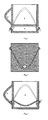
- a gutter 2 with two upper and two lower points can be designed like a closed (beginning and end connected) double wave (sinusoid), this embodiment being the optimal, because it enables maximally efficient capturing of the drip.
- Upper points of the gutter can be located at different levels for realization of the designer's idea ( Fig.17 ).
- the gutter can be zigzag-shaped with pointed ends (upper and/or lower points) ( Fig.13 ), while the holes of the storage chamber can be triangular, rhomboid, square, rectangular ( Fig.13-14 ) in shape.
- holes can be round, oval, or semicircular ( Fig.12 , 16-17 ) in shape. Holes (hole) of the storage chamber (in the rear wall) can be made at the right angle ( Fig.1 ) or with a tilt ( Fig.3 ).
- the shape of the gutter can vary: it can be straight, wavy, arch bent to different sides, upwards or downwards ( Fig.13 , 15-17 ).
- the gutter can be spiral ( Fig.12 ). There can be a separate gutter for each hole, spiral or of other shape allowing for liquid flow. Such gutter s can intersect crossways or run parallel.
- the gutter can be made of separate elements, like cascading steps, tilted and allowing for gradual flow of the liquid to the hole (holes), like the tiled roof ( Fig.14 ).
- the gutter 2 can consist of two parts ( Fig.7, 8 ) and have its ends connected to the hole with a bowl 3 ( Fig.7-9 ).
- hole can be formed by the bowl itself 3 ( Fig.8, 9 ).
- Profile of the gutter can be vary, i.g. flat with a sharp petal-shaped edge ( Fig. 12-17 ), or thick and with rounded edge ( Fig.20 ).
- the gutter with a rounded profile is better protected from chipping and usage-related damages.
- the gutter can also be formed by the difference in diameters/sizes of the upper (above the gutter) and lower (below the gutter) parts of the beverage mug ( Fig.18-19 ).
- the gutter can be deepened into the wall, fully or partially ( Fig.21 ).
- the walls of the beverage mug can be vertical or tilted, which provides for increase or decrease of the size of the main opening in relation to the bottom (narrowing or widening of the beverage mug upwards), they can also be straight or freely bent, for example, narrow (beverage mug with a waist) or widen (barrel-shaped) in the middle part of the beverage mug ( Fig.22 ).
- the walls narrowing the size of the main opening in relation to the bottom (narrow upwards) are the most effective in terms of drip collection.
- the body of the beverage mug can be circular, square, rectangular, rhomboid, oval, triangular, polygonal (five, six, or more angles), or of other shape ( Fig.23 ). It can be rectangular, while upper and lower points of the gutter, holes of the storage chamber coincide with angles of the main bowl.
- Beverage mug can be comprised of three elements: 1 - body including the walls, furrow and bottom of the main container; 2 - handle; 3 - bottom of the additional space (added container). Then the elements are brought together/fixed. Manufacturing of the body with the walls, furrow, and bottom of the main container together with a handle is also possible.
- Fig.24 presents the matrix (parts of the matrix are connected along the gutter line), and longitudinal section of the body of the beverage mug made by single-object casting.
- Inner and outer walls of the beverage mug are divided.
- the main bowl is formed by the inner bottom together with the inner walls becoming, along the upper rim of the beverage mug, the outer lateral walls with the gutter, handle, and outer bottom.
- the storage chamber is formed by the slot between the inner and outer bottom, inner and outer rear walls.
- the distance between inner and outer rear walls can disappear in the process of casting due to increased thickness of the material and fusion of the inner and outer rear walls, which provides for higher durability of the beverage mug. It is possible to cast the beverage mug in a different way, so that the handle makes a separate element that is later attached/fixed.
- Ceramic beverage mug it is possible to make ceramic beverage mug by making the body without gutters made or cast separately and then attached to the walls.
- Form of the inner and outer walls can vary ( Fig.25 ): i.g. form of the inner walls - round, outer walls - square, triangular, polygonal; form of the inner walls - oval, outer walls - rectangular, triangular, rhomboid, polygonal.
- the walls can fuse by forming fixity lines.
- Attachment 4 can be removable ( Fig. 8, 9 ) and attached to the body 1, i.g. threadedly, or with a help of magnet, suction cup, slots forming the lock when rotated (with "open” - “locked” positions) etc.
- the gutters are distanced from each other, and this is through this slot that the liquid flows to the bowl. Airtightness at the junction point can be ensured by a liner made of rubber or other elastic material.
- Attachment can be a separate element attached to the body by using the adhesive material, e.g. glue ensuring safe and airtight junction. Besides, the attachment can be attached to the main bowl in the process of manufacturing, which does not allow for its removal ( Fig. 10-11 ).
- Storage container might require special exchangeable plates 4 ( Fig.26 ) absorbing liquids like pampers, or hygienic tampons or pads. Plates can be filled with chemical substance turning liquid into get. Plates are to be changed periodically.
- the beverage mug with the additional space requiring plates can have more holes 3 ( Fig.26 ) i.g. 3-8 and more located around (along the perimeter) the beverage mug. Each hole can be connected with a gutter 2 ( Fig.26 ) collecting liquid it its sector only. Gutters can be formed by the spaces between the corners of the polygonal beverage mug. Fig. 26 presents the gutter formed by a gradual change of the profile.
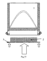
- the storage chamber without the bottom ( Fig.27 ).
- the plate absorbing the liquid 2 does have a bottom 3 hermetically attached to the body 1 of the beverage mug, i.g. adhesive tape ( Fig.27 ).
- adhesive tape Fig.27
- the beverage mug with a removable attachment 4 can be made of ceramics (majolica, faience, porcelain), glass, crystal, plastic, polymeric or composite materials, metal alloys, stainless steel, bronze, silver, and gold. Combination of the materials is also possible, i.g. main bowl made of glass or ceramic, attachment - metal or plastic.
- the liquid overflowing the rim of the main bowl 1 begins to flow down the rear falls to the gutter 2 directing it, through the holes 3, to the storage 4 chamber. Since in the process of drinking tilt axis of the beverage mug (if held in the usual way by the handle) is parallel to the axis of the holes, the liquid stays in the storage 4 chamber (not flowing out no matter how the beverage mug is tilted).
- the embodiment with two holes is the most efficient, because higher slope makes liquid flow faster. Besides, it is easier to wash the chamber with two holes.
Landscapes
- Table Devices Or Equipment (AREA)
- Details Of Rigid Or Semi-Rigid Containers (AREA)
- Devices For Dispensing Beverages (AREA)
Priority Applications (1)
| Application Number | Priority Date | Filing Date | Title |
|---|---|---|---|
| PL06717226T PL1889559T3 (pl) | 2005-06-03 | 2006-03-06 | Kubek do napojów |
Applications Claiming Priority (2)
| Application Number | Priority Date | Filing Date | Title |
|---|---|---|---|
| UAU200505282U UA13489U (en) | 2005-06-03 | 2005-06-03 | Dish for drinking |
| PCT/UA2006/000010 WO2006096146A1 (fr) | 2005-03-10 | 2006-03-06 | Recipient pour boire |
Publications (3)
| Publication Number | Publication Date |
|---|---|
| EP1889559A1 EP1889559A1 (en) | 2008-02-20 |
| EP1889559A4 EP1889559A4 (en) | 2009-05-27 |
| EP1889559B1 true EP1889559B1 (en) | 2012-11-28 |
Family
ID=37456991
Family Applications (1)
| Application Number | Title | Priority Date | Filing Date |
|---|---|---|---|
| EP06717226A Not-in-force EP1889559B1 (en) | 2005-06-03 | 2006-03-06 | Drinking vessel |
Country Status (9)
| Country | Link |
|---|---|
| US (1) | US20080073354A1 (ru) |
| EP (1) | EP1889559B1 (ru) |
| CN (1) | CN100574678C (ru) |
| BR (1) | BRPI0613209A2 (ru) |
| EA (1) | EA012349B1 (ru) |
| HK (1) | HK1121655A1 (ru) |
| PL (1) | PL1889559T3 (ru) |
| UA (1) | UA13489U (ru) |
| WO (1) | WO2006096146A1 (ru) |
Families Citing this family (5)
| Publication number | Priority date | Publication date | Assignee | Title |
|---|---|---|---|---|
| CN103654159A (zh) * | 2013-11-30 | 2014-03-26 | 无锡大阿福信息科技有限公司 | 一种防漏水杯 |
| US20160106267A1 (en) * | 2014-10-15 | 2016-04-21 | Luis Javier Cisneros | Safety pocket for commercial kitchen utensils and methods of using the same |
| CN104367104A (zh) * | 2014-11-28 | 2015-02-25 | 韦棋 | 一种防止杯壁流水的杯子 |
| CN104545274A (zh) * | 2014-12-31 | 2015-04-29 | 庄景阳 | 一种带有回流孔的咖啡杯 |
| CN204654471U (zh) * | 2014-12-31 | 2015-09-23 | 庄景阳 | 一种带有回流孔的咖啡杯 |
Family Cites Families (17)
| Publication number | Priority date | Publication date | Assignee | Title |
|---|---|---|---|---|
| US166350A (en) * | 1875-08-03 | Improvement in cups for effervescing drinks | ||
| US608649A (en) * | 1898-08-09 | Tumbler | ||
| US1120428A (en) * | 1914-01-31 | 1914-12-08 | Leo J White | Drinking-cup and the like. |
| CH182932A (de) * | 1935-07-17 | 1936-03-15 | Spuehler Ernst | Kochtopf. |
| GB528111A (en) * | 1938-08-06 | 1940-10-23 | Bergedorfer Eisenwerk Ag | Improvements in milk heaters |
| US2921706A (en) * | 1958-02-05 | 1960-01-19 | Johnson Elvin | Protecting jacket for liquid containers |
| US3279638A (en) | 1965-04-12 | 1966-10-18 | James F Merry | Drip proof container |
| US3428214A (en) * | 1967-09-27 | 1969-02-18 | Vernon C De Leon | Spill-proof drinking cup |
| US3680330A (en) * | 1971-04-27 | 1972-08-01 | Joseph Francis Canosa | Cooling vessel for beverages |
| US4040535A (en) * | 1975-09-22 | 1977-08-09 | Helen I. Shephard | Condensation proof drinking glass assembly |
| US4733790A (en) * | 1981-07-14 | 1988-03-29 | Stein Donald P | Combination drip pan and container lid |
| SU1409216A1 (ru) * | 1985-12-19 | 1988-07-15 | В.Ю.Руденко | Поильник |
| JPH02104309A (ja) * | 1988-10-14 | 1990-04-17 | Koji Tonomura | 水滴落下防止コップ及びその製造方法 |
| CN2326111Y (zh) * | 1998-01-22 | 1999-06-30 | 陈成泽 | 防呛喝水杯 |
| US5975333A (en) | 1998-03-10 | 1999-11-02 | Lee; Thomas | Drip catch beverage mug |
| FR2810525B1 (fr) * | 2000-06-26 | 2002-09-13 | Seb Sa | Verseuse comportant un bec verseur anti-gouttes |
| US7530468B1 (en) * | 2005-08-23 | 2009-05-12 | Garvey Patrick J | Drinking apparatus |
-
2005
- 2005-06-03 UA UAU200505282U patent/UA13489U/uk unknown
-
2006
- 2006-03-06 CN CN200680019675A patent/CN100574678C/zh not_active Expired - Fee Related
- 2006-03-06 EA EA200702679A patent/EA012349B1/ru not_active IP Right Cessation
- 2006-03-06 WO PCT/UA2006/000010 patent/WO2006096146A1/ru active Application Filing
- 2006-03-06 PL PL06717226T patent/PL1889559T3/pl unknown
- 2006-03-06 BR BRPI0613209-0A patent/BRPI0613209A2/pt not_active IP Right Cessation
- 2006-03-06 EP EP06717226A patent/EP1889559B1/en not_active Not-in-force
-
2007
- 2007-12-03 US US11/949,335 patent/US20080073354A1/en not_active Abandoned
-
2008
- 2008-11-27 HK HK08112955.0A patent/HK1121655A1/xx not_active IP Right Cessation
Also Published As
| Publication number | Publication date |
|---|---|
| EP1889559A4 (en) | 2009-05-27 |
| WO2006096146A1 (fr) | 2006-09-14 |
| EP1889559A1 (en) | 2008-02-20 |
| CN100574678C (zh) | 2009-12-30 |
| HK1121655A1 (en) | 2009-04-30 |
| WO2006096146A8 (fr) | 2008-01-03 |
| WO2006096146B1 (fr) | 2007-03-15 |
| CN101188961A (zh) | 2008-05-28 |
| UA13489U (en) | 2006-04-17 |
| BRPI0613209A2 (pt) | 2010-12-28 |
| EA200702679A1 (ru) | 2008-04-28 |
| EA012349B1 (ru) | 2009-10-30 |
| PL1889559T3 (pl) | 2013-05-31 |
| US20080073354A1 (en) | 2008-03-27 |
Similar Documents
| Publication | Publication Date | Title |
|---|---|---|
| EP1889559B1 (en) | Drinking vessel | |
| FI122800B (fi) | Teekuppi | |
| US7530468B1 (en) | Drinking apparatus | |
| US20210106162A1 (en) | Pour over type systems and methods for separating an extract from a suspension | |
| CN102961005A (zh) | 中式汤匙 | |
| US7472647B2 (en) | Egg separators | |
| KR101559660B1 (ko) | 기름 및 건데기 분리용 다용도 국자 | |
| CN203524521U (zh) | 一种集碱式净水开水容器 | |
| JP2016016036A (ja) | 匙およびお玉 | |
| JP7350032B2 (ja) | 茶こし付き飲用ボトル | |
| JPH0111110Y2 (ru) | ||
| US20190099031A1 (en) | Drinking vessel with a spillage receptacle | |
| CN210810341U (zh) | 一种分享饮料杯 | |
| CN218889574U (zh) | 一种滤油勺 | |
| JP6898005B2 (ja) | コップ | |
| CN102133022A (zh) | 茶壶形去油去渣汤勺 | |
| CN201353302Y (zh) | 防溢中药煲锅 | |
| JP3055830U (ja) | 水切り容器 | |
| TWM637161U (zh) | 具導水功能的冰鏟 | |
| CN115769971A (zh) | 一种浮力茶漏及茶壶 | |
| KR200316961Y1 (ko) | 오뚜기형 국자 | |
| CN202477209U (zh) | 防溢茶杯 | |
| PL2931S2 (pl) | Zestaw naczyn stolowych szklanych | |
| UA79980C2 (en) | Cup with collector of flowing liquid | |
| JP2006075206A (ja) | しずく受け付きカップ |
Legal Events
| Date | Code | Title | Description |
|---|---|---|---|
| PUAI | Public reference made under article 153(3) epc to a published international application that has entered the european phase |
Free format text: ORIGINAL CODE: 0009012 |
|
| 17P | Request for examination filed |
Effective date: 20071221 |
|
| AK | Designated contracting states |
Kind code of ref document: A1 Designated state(s): AT BE BG CH CY CZ DE DK EE ES FI FR GB GR HU IE IS IT LI LT LU LV MC NL PL PT RO SE SI SK TR |
|
| DAX | Request for extension of the european patent (deleted) | ||
| A4 | Supplementary search report drawn up and despatched |
Effective date: 20090423 |
|
| 17Q | First examination report despatched |
Effective date: 20090807 |
|
| GRAP | Despatch of communication of intention to grant a patent |
Free format text: ORIGINAL CODE: EPIDOSNIGR1 |
|
| GRAS | Grant fee paid |
Free format text: ORIGINAL CODE: EPIDOSNIGR3 |
|
| GRAA | (expected) grant |
Free format text: ORIGINAL CODE: 0009210 |
|
| AK | Designated contracting states |
Kind code of ref document: B1 Designated state(s): AT BE BG CH CY CZ DE DK EE ES FI FR GB GR HU IE IS IT LI LT LU LV MC NL PL PT RO SE SI SK TR |
|
| REG | Reference to a national code |
Ref country code: GB Ref legal event code: FG4D |
|
| REG | Reference to a national code |
Ref country code: CH Ref legal event code: EP |
|
| REG | Reference to a national code |
Ref country code: AT Ref legal event code: REF Ref document number: 585705 Country of ref document: AT Kind code of ref document: T Effective date: 20121215 |
|
| REG | Reference to a national code |
Ref country code: IE Ref legal event code: FG4D |
|
| REG | Reference to a national code |
Ref country code: DE Ref legal event code: R096 Ref document number: 602006033322 Country of ref document: DE Effective date: 20130117 |
|
| REG | Reference to a national code |
Ref country code: AT Ref legal event code: MK05 Ref document number: 585705 Country of ref document: AT Kind code of ref document: T Effective date: 20121128 |
|
| REG | Reference to a national code |
Ref country code: NL Ref legal event code: VDEP Effective date: 20121128 |
|
| REG | Reference to a national code |
Ref country code: LT Ref legal event code: MG4D |
|
| PG25 | Lapsed in a contracting state [announced via postgrant information from national office to epo] |
Ref country code: FI Free format text: LAPSE BECAUSE OF FAILURE TO SUBMIT A TRANSLATION OF THE DESCRIPTION OR TO PAY THE FEE WITHIN THE PRESCRIBED TIME-LIMIT Effective date: 20121128 Ref country code: SE Free format text: LAPSE BECAUSE OF FAILURE TO SUBMIT A TRANSLATION OF THE DESCRIPTION OR TO PAY THE FEE WITHIN THE PRESCRIBED TIME-LIMIT Effective date: 20121128 Ref country code: LT Free format text: LAPSE BECAUSE OF FAILURE TO SUBMIT A TRANSLATION OF THE DESCRIPTION OR TO PAY THE FEE WITHIN THE PRESCRIBED TIME-LIMIT Effective date: 20121128 Ref country code: ES Free format text: LAPSE BECAUSE OF FAILURE TO SUBMIT A TRANSLATION OF THE DESCRIPTION OR TO PAY THE FEE WITHIN THE PRESCRIBED TIME-LIMIT Effective date: 20130311 |
|
| PG25 | Lapsed in a contracting state [announced via postgrant information from national office to epo] |
Ref country code: PT Free format text: LAPSE BECAUSE OF FAILURE TO SUBMIT A TRANSLATION OF THE DESCRIPTION OR TO PAY THE FEE WITHIN THE PRESCRIBED TIME-LIMIT Effective date: 20130328 Ref country code: SI Free format text: LAPSE BECAUSE OF FAILURE TO SUBMIT A TRANSLATION OF THE DESCRIPTION OR TO PAY THE FEE WITHIN THE PRESCRIBED TIME-LIMIT Effective date: 20121128 Ref country code: LV Free format text: LAPSE BECAUSE OF FAILURE TO SUBMIT A TRANSLATION OF THE DESCRIPTION OR TO PAY THE FEE WITHIN THE PRESCRIBED TIME-LIMIT Effective date: 20121128 Ref country code: GR Free format text: LAPSE BECAUSE OF FAILURE TO SUBMIT A TRANSLATION OF THE DESCRIPTION OR TO PAY THE FEE WITHIN THE PRESCRIBED TIME-LIMIT Effective date: 20130301 Ref country code: BE Free format text: LAPSE BECAUSE OF FAILURE TO SUBMIT A TRANSLATION OF THE DESCRIPTION OR TO PAY THE FEE WITHIN THE PRESCRIBED TIME-LIMIT Effective date: 20121128 |
|
| REG | Reference to a national code |
Ref country code: PL Ref legal event code: T3 |
|
| PG25 | Lapsed in a contracting state [announced via postgrant information from national office to epo] |
Ref country code: AT Free format text: LAPSE BECAUSE OF FAILURE TO SUBMIT A TRANSLATION OF THE DESCRIPTION OR TO PAY THE FEE WITHIN THE PRESCRIBED TIME-LIMIT Effective date: 20121128 |
|
| PG25 | Lapsed in a contracting state [announced via postgrant information from national office to epo] |
Ref country code: CY Free format text: LAPSE BECAUSE OF FAILURE TO SUBMIT A TRANSLATION OF THE DESCRIPTION OR TO PAY THE FEE WITHIN THE PRESCRIBED TIME-LIMIT Effective date: 20121128 Ref country code: EE Free format text: LAPSE BECAUSE OF FAILURE TO SUBMIT A TRANSLATION OF THE DESCRIPTION OR TO PAY THE FEE WITHIN THE PRESCRIBED TIME-LIMIT Effective date: 20121128 Ref country code: SK Free format text: LAPSE BECAUSE OF FAILURE TO SUBMIT A TRANSLATION OF THE DESCRIPTION OR TO PAY THE FEE WITHIN THE PRESCRIBED TIME-LIMIT Effective date: 20121128 Ref country code: BG Free format text: LAPSE BECAUSE OF FAILURE TO SUBMIT A TRANSLATION OF THE DESCRIPTION OR TO PAY THE FEE WITHIN THE PRESCRIBED TIME-LIMIT Effective date: 20130228 Ref country code: CZ Free format text: LAPSE BECAUSE OF FAILURE TO SUBMIT A TRANSLATION OF THE DESCRIPTION OR TO PAY THE FEE WITHIN THE PRESCRIBED TIME-LIMIT Effective date: 20121128 Ref country code: DK Free format text: LAPSE BECAUSE OF FAILURE TO SUBMIT A TRANSLATION OF THE DESCRIPTION OR TO PAY THE FEE WITHIN THE PRESCRIBED TIME-LIMIT Effective date: 20121128 |
|
| PG25 | Lapsed in a contracting state [announced via postgrant information from national office to epo] |
Ref country code: RO Free format text: LAPSE BECAUSE OF FAILURE TO SUBMIT A TRANSLATION OF THE DESCRIPTION OR TO PAY THE FEE WITHIN THE PRESCRIBED TIME-LIMIT Effective date: 20121128 Ref country code: NL Free format text: LAPSE BECAUSE OF FAILURE TO SUBMIT A TRANSLATION OF THE DESCRIPTION OR TO PAY THE FEE WITHIN THE PRESCRIBED TIME-LIMIT Effective date: 20121128 |
|
| PLBE | No opposition filed within time limit |
Free format text: ORIGINAL CODE: 0009261 |
|
| STAA | Information on the status of an ep patent application or granted ep patent |
Free format text: STATUS: NO OPPOSITION FILED WITHIN TIME LIMIT |
|
| PG25 | Lapsed in a contracting state [announced via postgrant information from national office to epo] |
Ref country code: MC Free format text: LAPSE BECAUSE OF NON-PAYMENT OF DUE FEES Effective date: 20130331 |
|
| REG | Reference to a national code |
Ref country code: CH Ref legal event code: PL |
|
| 26N | No opposition filed |
Effective date: 20130829 |
|
| REG | Reference to a national code |
Ref country code: DE Ref legal event code: R097 Ref document number: 602006033322 Country of ref document: DE Effective date: 20130829 |
|
| REG | Reference to a national code |
Ref country code: IE Ref legal event code: MM4A |
|
| PG25 | Lapsed in a contracting state [announced via postgrant information from national office to epo] |
Ref country code: CH Free format text: LAPSE BECAUSE OF NON-PAYMENT OF DUE FEES Effective date: 20130331 Ref country code: LI Free format text: LAPSE BECAUSE OF NON-PAYMENT OF DUE FEES Effective date: 20130331 Ref country code: IE Free format text: LAPSE BECAUSE OF NON-PAYMENT OF DUE FEES Effective date: 20130306 |
|
| PGFP | Annual fee paid to national office [announced via postgrant information from national office to epo] |
Ref country code: DE Payment date: 20140326 Year of fee payment: 9 |
|
| PGFP | Annual fee paid to national office [announced via postgrant information from national office to epo] |
Ref country code: IT Payment date: 20140326 Year of fee payment: 9 Ref country code: TR Payment date: 20140224 Year of fee payment: 9 Ref country code: PL Payment date: 20140213 Year of fee payment: 9 |
|
| PGFP | Annual fee paid to national office [announced via postgrant information from national office to epo] |
Ref country code: GB Payment date: 20140327 Year of fee payment: 9 |
|
| PGFP | Annual fee paid to national office [announced via postgrant information from national office to epo] |
Ref country code: FR Payment date: 20140326 Year of fee payment: 9 |
|
| PG25 | Lapsed in a contracting state [announced via postgrant information from national office to epo] |
Ref country code: LU Free format text: LAPSE BECAUSE OF NON-PAYMENT OF DUE FEES Effective date: 20130306 Ref country code: HU Free format text: LAPSE BECAUSE OF FAILURE TO SUBMIT A TRANSLATION OF THE DESCRIPTION OR TO PAY THE FEE WITHIN THE PRESCRIBED TIME-LIMIT; INVALID AB INITIO Effective date: 20060306 |
|
| REG | Reference to a national code |
Ref country code: DE Ref legal event code: R119 Ref document number: 602006033322 Country of ref document: DE |
|
| GBPC | Gb: european patent ceased through non-payment of renewal fee |
Effective date: 20150306 |
|
| PG25 | Lapsed in a contracting state [announced via postgrant information from national office to epo] |
Ref country code: IT Free format text: LAPSE BECAUSE OF NON-PAYMENT OF DUE FEES Effective date: 20150306 |
|
| REG | Reference to a national code |
Ref country code: FR Ref legal event code: ST Effective date: 20151130 |
|
| PG25 | Lapsed in a contracting state [announced via postgrant information from national office to epo] |
Ref country code: GB Free format text: LAPSE BECAUSE OF NON-PAYMENT OF DUE FEES Effective date: 20150306 Ref country code: DE Free format text: LAPSE BECAUSE OF NON-PAYMENT OF DUE FEES Effective date: 20151001 |
|
| PG25 | Lapsed in a contracting state [announced via postgrant information from national office to epo] |
Ref country code: FR Free format text: LAPSE BECAUSE OF NON-PAYMENT OF DUE FEES Effective date: 20150331 |
|
| PG25 | Lapsed in a contracting state [announced via postgrant information from national office to epo] |
Ref country code: PL Free format text: LAPSE BECAUSE OF NON-PAYMENT OF DUE FEES Effective date: 20150306 |
|
| PG25 | Lapsed in a contracting state [announced via postgrant information from national office to epo] |
Ref country code: IS Free format text: LAPSE BECAUSE OF FAILURE TO SUBMIT A TRANSLATION OF THE DESCRIPTION OR TO PAY THE FEE WITHIN THE PRESCRIBED TIME-LIMIT Effective date: 20121128 |
|
| PG25 | Lapsed in a contracting state [announced via postgrant information from national office to epo] |
Ref country code: TR Free format text: LAPSE BECAUSE OF NON-PAYMENT OF DUE FEES Effective date: 20150306 |