EP1889014B1 - Oval-zahnradzähler - Google Patents
Oval-zahnradzähler Download PDFInfo
- Publication number
- EP1889014B1 EP1889014B1 EP05755574.0A EP05755574A EP1889014B1 EP 1889014 B1 EP1889014 B1 EP 1889014B1 EP 05755574 A EP05755574 A EP 05755574A EP 1889014 B1 EP1889014 B1 EP 1889014B1
- Authority
- EP
- European Patent Office
- Prior art keywords
- oval gear
- trigger wheel
- sensor means
- gmr
- sensor
- Prior art date
- Legal status (The legal status is an assumption and is not a legal conclusion. Google has not performed a legal analysis and makes no representation as to the accuracy of the status listed.)
- Active
Links
- 230000005291 magnetic effect Effects 0.000 claims description 48
- 239000012530 fluid Substances 0.000 claims description 24
- 238000011156 evaluation Methods 0.000 claims description 15
- 238000005259 measurement Methods 0.000 claims description 12
- 239000007788 liquid Substances 0.000 description 9
- 238000010276 construction Methods 0.000 description 5
- 239000000126 substance Substances 0.000 description 4
- 230000008901 benefit Effects 0.000 description 3
- 238000004140 cleaning Methods 0.000 description 3
- 230000000249 desinfective effect Effects 0.000 description 3
- 238000001514 detection method Methods 0.000 description 3
- 230000006870 function Effects 0.000 description 3
- 239000000463 material Substances 0.000 description 3
- 238000009738 saturating Methods 0.000 description 3
- 238000005406 washing Methods 0.000 description 3
- 230000008859 change Effects 0.000 description 2
- 230000008878 coupling Effects 0.000 description 2
- 238000010168 coupling process Methods 0.000 description 2
- 238000005859 coupling reaction Methods 0.000 description 2
- 238000006073 displacement reaction Methods 0.000 description 2
- 230000000694 effects Effects 0.000 description 2
- 230000001939 inductive effect Effects 0.000 description 2
- 239000012263 liquid product Substances 0.000 description 2
- 238000012544 monitoring process Methods 0.000 description 2
- 230000003287 optical effect Effects 0.000 description 2
- 229920003023 plastic Polymers 0.000 description 2
- 239000004033 plastic Substances 0.000 description 2
- 238000011160 research Methods 0.000 description 2
- 230000003321 amplification Effects 0.000 description 1
- 238000006243 chemical reaction Methods 0.000 description 1
- 238000012937 correction Methods 0.000 description 1
- 230000000593 degrading effect Effects 0.000 description 1
- 230000001419 dependent effect Effects 0.000 description 1
- 238000011161 development Methods 0.000 description 1
- 238000010586 diagram Methods 0.000 description 1
- 238000005516 engineering process Methods 0.000 description 1
- 230000005294 ferromagnetic effect Effects 0.000 description 1
- 239000003302 ferromagnetic material Substances 0.000 description 1
- 239000007789 gas Substances 0.000 description 1
- 230000001771 impaired effect Effects 0.000 description 1
- 238000011065 in-situ storage Methods 0.000 description 1
- 230000002401 inhibitory effect Effects 0.000 description 1
- 238000004519 manufacturing process Methods 0.000 description 1
- 230000007246 mechanism Effects 0.000 description 1
- 238000000034 method Methods 0.000 description 1
- 238000003199 nucleic acid amplification method Methods 0.000 description 1
- 230000010355 oscillation Effects 0.000 description 1
- 238000012545 processing Methods 0.000 description 1
- 238000005086 pumping Methods 0.000 description 1
- 238000005096 rolling process Methods 0.000 description 1
- 230000001960 triggered effect Effects 0.000 description 1
Images

Classifications
-
- G—PHYSICS
- G01—MEASURING; TESTING
- G01F—MEASURING VOLUME, VOLUME FLOW, MASS FLOW OR LIQUID LEVEL; METERING BY VOLUME
- G01F15/00—Details of, or accessories for, apparatus of groups G01F1/00 - G01F13/00 insofar as such details or appliances are not adapted to particular types of such apparatus
- G01F15/06—Indicating or recording devices
- G01F15/065—Indicating or recording devices with transmission devices, e.g. mechanical
- G01F15/066—Indicating or recording devices with transmission devices, e.g. mechanical involving magnetic transmission devices
-
- G—PHYSICS
- G01—MEASURING; TESTING
- G01F—MEASURING VOLUME, VOLUME FLOW, MASS FLOW OR LIQUID LEVEL; METERING BY VOLUME
- G01F3/00—Measuring the volume flow of fluids or fluent solid material wherein the fluid passes through the meter in successive and more or less isolated quantities, the meter being driven by the flow
- G01F3/02—Measuring the volume flow of fluids or fluent solid material wherein the fluid passes through the meter in successive and more or less isolated quantities, the meter being driven by the flow with measuring chambers which expand or contract during measurement
- G01F3/04—Measuring the volume flow of fluids or fluent solid material wherein the fluid passes through the meter in successive and more or less isolated quantities, the meter being driven by the flow with measuring chambers which expand or contract during measurement having rigid movable walls
- G01F3/06—Measuring the volume flow of fluids or fluent solid material wherein the fluid passes through the meter in successive and more or less isolated quantities, the meter being driven by the flow with measuring chambers which expand or contract during measurement having rigid movable walls comprising members rotating in a fluid-tight or substantially fluid-tight manner in a housing
- G01F3/10—Geared or lobed impeller meters
Definitions
- the present invention relates to an oval gear meter for volume flow measurement..
- fluid is used herein to identify any continuous substance that is tending to flow or conform to the outline of its container. So the term fluid encompasses liquids and gases.
- a particularly interesting application of the present invention is for liquids, in particular liquid products and chemicals used in cleaning, washing, disinfecting, rinsing or the like.
- the volume flow of a fluid can be measured by a positive displacement flow meter.
- a very common, precise positive displacement flow meter is an oval gear meter ( US 5,992,230 A ).
- An oval gear meter comprises a housing that forms an oval gear chamber with a fluid inlet and a fluid outlet.
- a pair of oval gear wheels is positioned in the chamber so that each can rotate about its specific rotational axis in a way that the two oval gear wheels provide an involute toothing.
- a traditional oval gear meter provides a pair of toothed oval gear wheels that are positioned relative to one another in the oval gear chamber such that the gear teeth disposed on their surfaces mesh together at the point of atriculation and remain as such during an entire rotation cycle.
- none of the fluid being metered actually passes directly between the oval gear wheels themselves.
- the intermeshing wheels in combination with the inherent viscosity of the fluid being metered is intended to prevent the flow of fluid between the two articulating wheel surfaces.
- the metered fluid is swept out in the precisely measured pockets created by the oval shape of the oval gear wheel and the inner chamber wall as the oval gear wheels rotate about their respective rotational axes.
- the above explained traditional construction is widely used.
- the prior art provides a modified construction of an oval gear meter with a pair of non-intermeshing, spaced apart, smooth surface oval gear wheels within the oval gear chamber. Those two oval gear wheels within the oval gear chamber are gear wheels within the oval gear chamber are interconnected by a pair of intermeshing timing gears that are disposed outside of the oval gear chamber.
- oval gear meter is preferably used with a liquid as working fluid, and more particularly with a liquid of higher relative viscosity.
- the oval gear wheels are spaced apart as well as from the inner walls of the oval gear chamber such that the liquid itself forms a liquid seal at all gaps and thus the working fluid is prevented from flowing through those gaps.
- This type of oval gear meter with an involute toothing provided without intermeshing contact between the oval gear wheels is said to reduce wear and tear of the metering system.
- the two oval gear wheels should move on rolling contact with practically no sliding friction therebetween.
- manufacturing tolerance and temperature influence prevents this ideal situation and demands either a true intermeshing pair of oval gear wheels or acceptance of minimal gaps between the oval gear wheels that are sealed by the working fluid, in particular the working liquid itself.
- the volume flow through an oval gear meter is measured indirectly by measuring the rotational speed of the oval gear wheels.
- a contactless magneto-reactive sensor means with one or two hall sensors is used. This sensor means is positioned outside the oval gear chamber either in a separate compartment of the housing or in a separate housing attached to the oval gear meter housing.
- the housing walls must be from a material like plastics that is not inhibiting the measurement by the magneto-reactive sensor means.
- the sensor means is assigned to at least one of the two oval gear wheels.
- This specific wheel is provided with normally two permanent magnets positioned separate from each other at a distance along the longitudinal axis of this oval gear wheel which thus is the trigger wheel.
- the two permanent magnets are parallel poled so that each one forms its own magnetic field.
- One complete rotation of the magnetic star gear will thus result in twelve detections/impulses by the sensor/counter.
- the non-uniform spacing of the magnetic radials accommodates the relatively non-uniform rotation rate of the shaft, i.e. the trigger wheel, i.e. the coupled oval gear wheel. This leads to a more uniformly spaced series of detection events.
- a simple calibration performed by an external logic controller or evaluation electronics, perhaps by a programmable logic control, can map each detection event as recorded by the sensor/counter to a known quantity or volume of fluid, and present this information in a digital format as output for further processing by associated equipment.
- the resolution of the magneto-reactive sensor means or inductive proximity sensor means for a sealed oval gear chamber where no magnetic star type gear can be used, is too low for a true real-time control or for measurement of low flow rates. As the precision of fluid pumps increases in particular for low flow rates, measuring the volume flow should follow this development.
- Optical encoders are insufficient in particular for the preferred field of application in cleaning, washing, disinfecting or the like, because of problematic ambient conditions, chemical attack, pressure conditions etc.
- JP-A-62-269014 relates to detecting rotational information of a flowmeter as specific analogue signal proportional to the number of rotations.
- the present invention meets above mentioned object with an oval gear meter for volume flow measurement with the features of claim 1
- the trigger wheel is provided with a magnetic system that generates a generally homogeneous magnetic field along one axis of symmetry of the trigger wheel, preferably the major axis of the trigger wheel.
- the magnetic field of the permanent magnet is oriented perpendicular to the middle plane of trigger wheel.
- the orientation of the magnetic field according to the invention is more or less parallel to the middle plane of the trigger wheel.
- This generally homogenous magnetic field is therefore generally symmetrical relative to the rotational axis of the trigger wheel. This generally homogeneous magnetic field is thus rotating in substantially the same way as the trigger wheel does.
- the continuously rotating magnetic field is monitored by a specific magneto-reactive sensor means. There is no counting done but a true monitoring of this rotation.
- a GMR-spin valve sensor means contains two magnetic layer.
- a pinned or fixed direction layer is combined with a free or movable direction layer.
- the movable layer aligns with the field lines of the applied magnetic field. The angle between the fixed direction layer and the movable direction layer determines the electrical resistance of this sensor element.
- Positioning of the GMR-spin valve sensor means relative to the permanent magnet of the trigger wheel is important. It should be positioned generally concentrically relative to the rotational axis of the trigger wheel which is considered to be the rotational axis of the generally homogeneous magnetic field generated by the permanent magnet. "Generally concentrically” here is not meant in a strict geometrical sense but means an orientation of the sensor means that leads to the correct analog monitoring of the rotating magnetic field mentioned above.
- the advantage of a GMR-spin valve sensor means versus a HALL-sensor means lies in the fact that it provides a sine output signal following the rotation of the homogeneous magnetic field provided by the permanent magnet means of the trigger wheel.
- a single GMR-sensor element is generally sufficient to monitor the rotation of the trigger wheel.
- precision of the measurement as well as variety of output signals increases with a more sophisticated GMR-sensor means.
- the GMR-sensor means is designed as a GMR-spin valve bridge sensor with two or, preferably, four GMR-spin valve sensor elements at 90° positions in two half-bridges.
- Such a GMR spin valve bridge sensor is available e.g. from NVE corporation with identification No. NVE AAV 001-11 and AAV 002-11.
- a GMR-spin valve bridge sensor provides four GMR resistors, rotated at 90° intervals in one package.
- the output of those four offset resistors can be configured to represent the sine function and the cosine function of the magnetic field that is applied to the complete sensor.
- Each sensor element contains two magnetic layers. A pinned, fixed direction layer and a free, movable direction layer.
- the generally homogeneous magnetic field of the trigger wheel must be strong enough to be a saturating magnetic field for the sensor elements. In the example mentioned here this is 2387 to 15915 A/m [30 to 200 Oersted].
- the evaluation electronics for this prior art general sensor system for shaft encoders uses the advantages of two half-bridges for cosine- and sine-functions (see above mentioned prior art document). This working principle of the evaluation electronics may be applied for the present GMR-spin valve sensor means as well.
- Fig. 1 shows the general principle of an oval gear meter for volume flow measurement.
- Fig. 1 shows a housing 1 with an oval gear chamber 2.
- the housing 1 should be of a material that will not inhibit measurement of magnetic fields generated within the housing 1.
- the housing 1 should be from a sufficiently rigid plastics material.
- the housing 1 comprises a fluid inlet 3 to the oval gear chamber 2 and a fluid outlet 4 from the oval gear chamber 2.
- Two oval gear wheels 5, 6 are positioned in the oval gear chamber 2 and are forming an involute toothing with each other. So this type of volume flow meter is very precise from a mechanical point of view.
- the pair of oval gear wheels 5, 6 in the chamber 2 may form an intermeshing involute toothing or may be provided with smooth surfaces and thus form a non-intermeshing involute toothing where the fluid that is being metered forms seals between the rotating surfaces of the oval gear wheels 5, 6 as well as between the oval gear wheels 5, 6 and the wall of the oval gear chamber 2.
- oval gear wheels 5, 6 together form a non-intermeshing involute toothing
- a pair of generally oval intermeshing timing gears positioned outside of the oval gear chamber 2 but coupled to the oval gears wheels 5, 6 within the chamber 2.
- the present invention is intended to be used with all kinds of fluids, but preferably with liquids and preferably in the field of liquid products and chemicals used for cleaning, washing, disinfecting, rinsing or the like.
- Measurement of the volume flow is provided by measurement of the rotation of the oval gear wheels 5, 6.
- this system comprises a contactless magneto-reactive sensor means 7 ( Fig. 2 ) positioned outside of the chamber 2.
- the chamber 2 may be sealed (apart from the fluid inlet 3 and fluid outlet 4).
- an evaluation electronics 8 for evaluating the signals of the sensor means 7 is provided, too.
- one of the oval gear wheels 6, 7, namely the oval gear wheel 6, is provided with at least one permanent magnet 9 and thus forms a trigger wheel.
- an external timing gear may be provided with this permanent magnet and then is the trigger wheel.
- the sensor means 7 is positioned in an appropriate position relative to the trigger wheel 6 so that the sensor means 7 is adapted to measure the rotation of the oval gear wheels 5, 6 by measuring the rotation of the trigger wheel 6.
- the magneto-reactive sensor means 7 is provided with mostly two HALL-sensor elements that are counting the revolutions of the trigger wheel 6.
- the trigger wheel 6 there is equipped with two small, cylindrical permanent magnets 9 positioned at a distance along the major axis of the trigger wheel 6.
- the permanent magnets 9 are poled in parallel as explained in the introductory part of the description.
- Fig. 1 shows that the sensor means 7 indicated in dashed lines there is offset relative to the axis 6' of the trigger wheel 6, because the passing of the permanent magnet 9 past the HALL-sensor is relevant. In this system a counting of the impulses generated by the passing permanent magnets 9 takes place.
- the GMR sensor means 7 is positioned in a nearly full overlap with the trigger wheel 6, because the rotating generally homogeneous magnetic field shall be continuously monitored in its angular position by the GMR sensor (see Fig. 2 ).
- the permanent magnet 9 generates a generally homogeneous magnetic field along the major axis of the trigger wheel 6.
- the magnetic field is generally symmetrical relative to the rotational axis 6' of the trigger wheel 6.
- the resolution or evaluation may be somewhat impaired.
- the magnetic field extends along any axis that intersects with the rotational axis 6' of the trigger wheel 6. It is important that the magnetic field rotates about the rotational axis 6' of the trigger wheel 6 more or less in the same way as the trigger wheel 6 itself does.
- the strength of the magnetic field should be close to the saturating level of the sensor means 7 to eliminate errors by fluctuations of the magnetic field. In the embodiment explained above it would be between 2387 to 15915 A/m [30 and 200 Oersted].
- the generally homogeneous magnetic field which is generally symmetrical relative to the rotational axis 6' of the trigger wheel 6 and is extending along an axis of the trigger wheel 6 (parallel to the plane defined by the trigger wheel 6 itself) may be generated by a radial permanent magnet.
- a radial oriented permanent magnet is not only expensive but needs a large recess in the trigger wheel 6.
- the present embodiment uses the traditional two separate, preferably cylindrical permanent magnets 9 that are positioned at a distance along an axis of the trigger wheel 6. Those are oppositely poled to generate the intended homogeneous magnetic field along this axis.
- the two permanent magnets 9 are positioned with their N-S-axis generally orthogonal to the plane of the trigger wheel 6.
- the distance of the permanent magnets 9 depends on the strength of the magnetic field that is needed for reliable operation of the GMR-sensor means 7. Further, the distance of the GMR-sensor means 7 from the plane defined by the trigger wheel 6 is additionally an important factor for the layout of this oval gear meter.
- the length of the trigger wheel 6 along the major axis is about 17 mm, 22 mm or 35 mm, the size of each permanent magnet 9 (diameter) is about 4 mm, and the distance of the two permanent magnets 9 is about 9 mm, 12 mm or 18 mm.
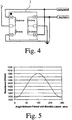
- the GMR-sensor means 7 comprises not only a single GMR-spin valve element but a full GMR-spin valve bridge sensor with four GMR resistors in one package, each resistor positioned at a 90° angle relative to the neighboring resistors ( Fig. 4 ).
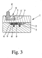
- Fig. 3 shows a vertical section through a preferred embodiment of the invention.
- the chip 7' of the GMR-sensor means 7 carrying the complete GMR-spin valve bridge sensor with four GMR-spin valve sensor elements (claim 6) is positioned exactly above the rotational axis 6' of the trigger wheel 6.
- the complete sensor means 7 with its evaluation electronics 8 and an interface 8' is positioned within a corresponding chamber 1' of the upper part of the housing 1.
- Fig. 5 shows the graph of the device resistance vs. the angle between the pinned layer and the movable layer in a GMR-sensor element.
- the intended signal amplitude of the sine-signal and the cosine-signal is achieved by an appropriately modified amplification.
- an automatic control as in the prior art of iC-Haus would be useful for the present purpose, as well.
- the sine and cosine signals may be digitized in a table so that they are used in a table look up procedure. Thus for each digital value of those two signals a single angle position of the trigger wheel 6 is assigned. The direction of rotation can be obtained from a comparison of two immediately following angle values. The specific problem of 360° / 0° has to be considered appropriately.
- the size of the oval gears wheels 5, 6 and the oval gear chamber 2 defines a particular volume for each revolution of the oval gear wheels 5, 6. According to this specific volume each angle value or step will be representing a specific volume. This is the calibration of the oval gear meter.
- a specific impulse sequence is representative for a specific volume flow.
- the output signal of the evaluation electronics 8 may be ml / imp.
- the evaluation electronics together 8 with the inventive GMR spin valve sensor means 7 allows for correction of negative impulses. This is necessary to eliminate pulses resulting from oscillations in the conduit system. In this regard the direction of the rotation must be measured and considered by the evaluation electronics 8.
- the system is particularly advantageous if combined with a corresponding fluid (in particular: liquid) pump.
- the pump may communicate with the evaluation electronics e.g. through a bus-system.
- the oval gear meter identifies itself at the beginning with an identification code containing all necessary data for identification of this specific oval gear meter as well as all calibration data.
- the central control unit or the control unit of the pump means receives from the oval gear meter or its evaluation electronics the maximum number of impulses per revolution. Impulses generated in the correct direction of flow are counted and impulses in the opposite direction are discounted.
- the angular positions for the relative sine and cosine outputs are stored in the memory means and can be electronically looked up in this table.
- the software must allow calibration of the oval gear meter in situ as well as manual input of a specific volume. All this can be programmed by the operator without restrictions. It is normally a programmable logic control that enables all this for normal applications.
- the pumping systems used will mostly employ electrically driven pump means with a sophisticated control interface.
- the present invention relies on a GMR spin valve sensor means for the oval gear meter.
- the GMR sensor means has proven to be manufactured reliably and economically, and to yield uniform measurement outputs over the complete lifetime in a stable, neither corroding nor degrading manner.
Claims (4)
- Ovalradzähler zur Volumenstrommessung, aufweisend:ein Gehäuse (1) mit einer Ovalrad-Kammer (2) mit einem Fluideinlass (3) und einem Fluidauslass (4),ein Paar Ovalräder (5, 6), die in der Kammer (2) positioniert sind und zusammen eine ineinandergreifende Evolventenverzahnung bilden,ein berührungsfreies Sensormittel (7) mit magnetoresistiven Sensorelementen, wobei die Sensormittel (7) außerhalb der Kammer (2) positioniert ist, undeine Auswertelektronik (8) zum Auswerten der Signale des berührungsfreien Sensormittels (7),wobei wenigstens eines der Ovalräder (5, 6) mit wenigstens einem Dauermagneten (9) versehen ist, um ein Triggerrad (6) auszubilden, und der Dauermagnet (9) ein grundsätzlich homogenes Magnetfeld entlang einer Symmetrieachse des Triggerrads (6) erzeugt, wobei das Magnetfeld grundsätzlich symmetrisch relativ zu der Rotationsachse (6') des Triggerrads (6) ist, undwobei das Sensormittel (7) grundsätzlich konzentrisch relativ zu der Rotationsachse (6') des Impulsgeberrads (6) in einer angemessenen Position relativ zu dem Triggerrad (6) positioniert ist, sodass das Sensormittel (7) dazu ausgebildet ist, die Rotation der Ovalräder (5, 6) durch Messen der Rotation des Triggerrads (6) zu messen,wobei das Sensormittel (7) ein GMR-Spin-Ventil-Brückensensor mit vier GMR-Spin-Ventil-Sensorelementen an 90°-Positionen in zwei Halbbrücken ist,wobei die zwei Halbbrücken dazu ausgebildet sind, eine Sinus-Ausgabe und eine Kosinus-Ausgabe an die Auswertelektronik bereitzustellen, unddie Auswertelektronik (8) ein Speichermittel umfasst, um eine Tabelle zu speichern, die jeden spezifischen Wert der Ausgabe-Sinus- und -Kosinussignale einer bestimmten Winkelposition des Triggerrads (6) zuweist.
- Ovalradzähler nach Anspruch 1, dadurch gekennzeichnet, dass das Triggerrad (6) mit einem einzelnen radialen Dauermagneten versehen ist, dessen mittlere Ebene parallel zu der Ebene des Triggerrads (6) ausgerichtet ist.
- Ovalradzähler nach Anspruch 1, dadurch gekennzeichnet, dass das Triggerrad (6) mit zwei separaten, entgegengesetzt gepolten, vorzugsweise zylindrischen Dauermagneten (9) versehen ist, die in einem Abstand entlang einer Achse, vorzugsweise der Hauptachse des Impulsgeberrads (6), positioniert sind.
- Ovalradzähler nach Anspruch 3, dadurch gekennzeichnet, dass die Länge des Triggerrads (6) entlang der Hauptachse etwa 17 mm, 22 mm oder 35 mm ist, die Größe jedes Dauermagneten (9) etwa 4 mm ist und der Abstand der zwei Dauermagneten (9) etwa 9 mm, 12 mm oder 18 mm ist.
Applications Claiming Priority (1)
| Application Number | Priority Date | Filing Date | Title |
|---|---|---|---|
| PCT/EP2005/006153 WO2006131134A1 (en) | 2005-06-08 | 2005-06-08 | Oval gear meter |
Publications (2)
| Publication Number | Publication Date |
|---|---|
| EP1889014A1 EP1889014A1 (de) | 2008-02-20 |
| EP1889014B1 true EP1889014B1 (de) | 2019-04-03 |
Family
ID=35677353
Family Applications (1)
| Application Number | Title | Priority Date | Filing Date |
|---|---|---|---|
| EP05755574.0A Active EP1889014B1 (de) | 2005-06-08 | 2005-06-08 | Oval-zahnradzähler |
Country Status (4)
| Country | Link |
|---|---|
| US (1) | US7523660B2 (de) |
| EP (1) | EP1889014B1 (de) |
| ES (1) | ES2726748T3 (de) |
| WO (1) | WO2006131134A1 (de) |
Families Citing this family (33)
| Publication number | Priority date | Publication date | Assignee | Title |
|---|---|---|---|---|
| FI119298B (fi) * | 2006-05-12 | 2008-09-30 | Osakeyhtioe Skf Aktiebolag | Soikiohammasratasmittari |
| US8312785B2 (en) * | 2008-06-20 | 2012-11-20 | Graco Minnesota Inc. | Involute gear teeth for fluid metering device |
| US8069719B2 (en) | 2009-02-11 | 2011-12-06 | Ecolab Usa Inc. | Gear flow meter with optical sensor |
| US20110031272A1 (en) * | 2009-08-05 | 2011-02-10 | Knight, Llc | Chemical dispensing systems and positive displacement flow meters therefor |
| KR100959629B1 (ko) * | 2009-08-11 | 2010-05-27 | 주식회사 디에이치플로우 | 넓은 감지 범위를 갖는 유량 적산계 |
| AU2010206097B2 (en) * | 2009-08-13 | 2013-02-14 | Trimec Industries Pty Ltd | Improved positive displacement flowmeter |
| JP4599454B1 (ja) * | 2009-09-07 | 2010-12-15 | 株式会社オーバル | 容積式気液二相流量計及び多相流量計測システム |
| AT508805B1 (de) * | 2009-10-09 | 2011-06-15 | Kral Ag | Durchflussmesseinrichtung |
| WO2011059477A2 (en) | 2009-10-30 | 2011-05-19 | Gea Farm Technologies, Inc. | Methods and apparatus for mixing dairy animal treatment chemicals |
| CN101975599B (zh) * | 2010-05-24 | 2012-05-02 | 上海神舟汽车节能环保有限公司 | 一种四磁钢椭圆齿轮流量计 |
| ES2676721T3 (es) | 2010-07-30 | 2018-07-24 | Ecolab Usa Inc. | Método y sistema para calibrar un sistema de distribución de líquido |
| US9618376B2 (en) | 2010-07-30 | 2017-04-11 | Ecolab Usa Inc. | Apparatus, method and system for calibrating a liquid dispensing system |
| US8166828B2 (en) | 2010-08-06 | 2012-05-01 | Ecolab USA, Inc. | Fluid flow meter |
| US20120047988A1 (en) * | 2010-08-25 | 2012-03-01 | Ecolab Usa Inc | Method, apparatus and system for accurately measuring and calibrating liquid components dispensed from a dispenser |
| ES2715206T3 (es) * | 2010-11-19 | 2019-06-03 | Vse Volumentechnik Gmbh | Procedimiento de evaluación de medidas de volumen y dispositivo de medida correspondiente |
| US8757009B2 (en) | 2010-12-08 | 2014-06-24 | Danaher Uk Industries Limited | Fuel dispenser flow meter sensor fraud prevention |
| DE102011011871A1 (de) * | 2011-01-06 | 2012-07-12 | Walter Mehnert | Verfahren und Vorrichtung zur Bestimmung der in einem Verbrauchs-Zeitintervall durch einen Durchflussmengenmesser strömenden Masse eines Fluids |
| EP2668473A1 (de) | 2011-01-24 | 2013-12-04 | M.T.R. Wireless Communications Ltd. | Durchflussmesservorrichtung |
| US8757010B2 (en) | 2011-04-20 | 2014-06-24 | Gilbarco Inc. | Fuel dispenser flow meter fraud detection and prevention |
| US8943901B2 (en) | 2013-03-15 | 2015-02-03 | Ecolab Usa Inc. | Fluid flow meter |
| AU2014232989A1 (en) | 2013-03-15 | 2015-11-05 | Gilbarco Inc. | Fuel dispenser flow meter fraud detection and prevention |
| US20160238419A1 (en) | 2013-09-30 | 2016-08-18 | Lincoln Industrial Corporation | Flow measuring device for lubrication systems |
| US9441998B2 (en) * | 2014-07-21 | 2016-09-13 | Ecolab Usa Inc. | Oval gear meter |
| US9835482B2 (en) | 2015-03-04 | 2017-12-05 | Ecolab Usa Inc. | Gear flow meter with out of product sensor |
| US10466152B2 (en) | 2015-10-07 | 2019-11-05 | Logilube, LLC | Fluid monitoring and management devices, fluid monitoring and management systems, and fluid monitoring and management methods |
| EP3371555A4 (de) * | 2015-10-20 | 2019-10-09 | LogiLube, LLC | Vorrichtungen, systeme und verfahren zur flüssigkeitsdurchflussüberwachung und -verwaltung |
| US10329942B2 (en) * | 2017-01-16 | 2019-06-25 | Natural Gas Solutions North America, Llc | Apparatus using magnets for harvesting energy on a metrology device |
| CN107219425B (zh) * | 2017-06-14 | 2019-05-17 | 中北大学 | 一种基于巨磁电阻磁敏感的金属密闭体内测试仪触发装置 |
| US10260923B2 (en) | 2017-07-25 | 2019-04-16 | Ecolab Usa Inc. | Fluid flow meter with normalized output |
| US10935407B2 (en) * | 2017-07-25 | 2021-03-02 | Ecolab Usa Inc. | Fluid flow meter with viscosity correction |
| US10126152B1 (en) * | 2017-07-25 | 2018-11-13 | Ecolab Usa Inc. | Fluid flow meter with linearization |
| IT201800007022A1 (it) * | 2018-07-09 | 2020-01-09 | Misuratore volumetrico di portata. | |
| CN109520581A (zh) * | 2019-01-02 | 2019-03-26 | 安徽天维仪表有限公司 | 一种无机械传动系统的微型椭圆齿轮流量计及加工方法 |
Citations (3)
| Publication number | Priority date | Publication date | Assignee | Title |
|---|---|---|---|---|
| US5992230A (en) * | 1997-11-15 | 1999-11-30 | Hoffer Flow Controls, Inc. | Dual rotor flow meter |
| US20040027732A1 (en) * | 2002-08-08 | 2004-02-12 | Brian Kelly | GMR spin valve sensor with ion implanted areas |
| US20060103381A1 (en) * | 2002-07-26 | 2006-05-18 | Peter Schmollngruber | Gmr sensor element and its use |
Family Cites Families (13)
| Publication number | Priority date | Publication date | Assignee | Title |
|---|---|---|---|---|
| US4224015A (en) * | 1977-01-19 | 1980-09-23 | Oval Engineering Co., Ltd. | Positive displacement flow meter with helical-toothed rotors |
| DE3321952C2 (de) * | 1983-06-18 | 1985-08-22 | Bopp & Reuther Gmbh, 6800 Mannheim | Elektromagnetischer Impulsaufnehmer für Durchflußmesser |
| JPH0641862B2 (ja) * | 1986-05-16 | 1994-06-01 | 株式会社オーバル | 流量発信器 |
| JPH0641863B2 (ja) * | 1986-10-09 | 1994-06-01 | 株式会社オーバル | 流量発信器 |
| DE4119236A1 (de) * | 1991-06-07 | 1992-12-10 | Geraetewerk Babelsberg Gmbh | Ovalrad-mengenmesser fuer kleine nennweiten |
| NL1004751C2 (nl) * | 1996-12-12 | 1998-06-15 | Instromet Bv | Meetinrichting voorzien van draaizuigers. |
| AU2001236910A1 (en) * | 2000-02-24 | 2001-09-03 | Data Industrial Corporation | Bi-directional flow sensor with integral direction indication |
| WO2002033364A1 (en) * | 2000-10-16 | 2002-04-25 | Isa - Instrumentação E Sistemas De Automação, Lda | Gauge comprising a magneto-resistive sensor, for liquid level remote measuring system on reservoirs |
| US6644947B2 (en) * | 2002-03-14 | 2003-11-11 | Tuthill Corporation | Wave tooth gears using identical non-circular conjugating pitch curves |
| FR2842913B1 (fr) * | 2002-07-23 | 2004-11-19 | Schlumberger Services Petrol | Dispositif compact de mesure de vitesse et de sens de rotation d'un objet |
| DE10318938B4 (de) | 2003-04-26 | 2007-10-11 | Gok Regler- Und Armaturengesellschaft Mbh & Co.Kg | Vorrichtung zur Messung des Füllstands einer in einem Behälter aufgenommenen Flüssigkeit |
| JP4259937B2 (ja) * | 2003-06-30 | 2009-04-30 | アルプス電気株式会社 | 角度検出センサ |
| DE102004027386A1 (de) * | 2004-06-04 | 2006-01-05 | Vse Volumentechnik Gmbh | Durchflussmengenfühler |
-
2005
- 2005-06-08 WO PCT/EP2005/006153 patent/WO2006131134A1/en active Application Filing
- 2005-06-08 ES ES05755574T patent/ES2726748T3/es active Active
- 2005-06-08 US US11/916,785 patent/US7523660B2/en active Active
- 2005-06-08 EP EP05755574.0A patent/EP1889014B1/de active Active
Patent Citations (3)
| Publication number | Priority date | Publication date | Assignee | Title |
|---|---|---|---|---|
| US5992230A (en) * | 1997-11-15 | 1999-11-30 | Hoffer Flow Controls, Inc. | Dual rotor flow meter |
| US20060103381A1 (en) * | 2002-07-26 | 2006-05-18 | Peter Schmollngruber | Gmr sensor element and its use |
| US20040027732A1 (en) * | 2002-08-08 | 2004-02-12 | Brian Kelly | GMR spin valve sensor with ion implanted areas |
Also Published As
| Publication number | Publication date |
|---|---|
| EP1889014A1 (de) | 2008-02-20 |
| US7523660B2 (en) | 2009-04-28 |
| WO2006131134A1 (en) | 2006-12-14 |
| US20080202255A1 (en) | 2008-08-28 |
| ES2726748T3 (es) | 2019-10-09 |
Similar Documents
| Publication | Publication Date | Title |
|---|---|---|
| EP1889014B1 (de) | Oval-zahnradzähler | |
| US6812694B2 (en) | Magnetic sensor adjusting method, magnetic sensor adjusting device and magnetic sensor | |
| CN101490513B (zh) | 椭圆形齿轮计 | |
| CN102007328B (zh) | 具有磁式角度传感器的阀致动器和包括该传感器的系统 | |
| US20100199758A1 (en) | Flow meter | |
| AU1962800A (en) | Device and method for detecting the relative position of a rotatable body | |
| CN1957236B (zh) | 流量检测器 | |
| US7650800B2 (en) | Flow sensor and method for measuring the volume and/or flow speed of a medium | |
| JPH08189839A (ja) | 位置検出装置及び位置検出方法 | |
| CN103282750A (zh) | 体积测量分析方法和体积测量装置 | |
| DK1994375T3 (en) | The volume measuring device with sensor | |
| JP2018530759A (ja) | ダイヤフラム変位流量計 | |
| JPH03257329A (ja) | 流量計 | |
| EP3783319B1 (de) | Durchflussmesser | |
| KR101582529B1 (ko) | 카운터 타입의 앱솔루트 엔코더 | |
| AT519061B1 (de) | Volumenzähler | |
| JPH06160149A (ja) | 容積流量計 | |
| KR100959629B1 (ko) | 넓은 감지 범위를 갖는 유량 적산계 | |
| JP4245414B2 (ja) | 回転検出器、容積式流量計、及び回転検出方法 | |
| AU2007251522B2 (en) | Oval gear meter | |
| EP1540282A2 (de) | Linearpositionsmessung mit zwei zahnradsensoren | |
| US7652471B2 (en) | Magnetic tagging of magnetoresistive sensors | |
| JPH04127521U (ja) | 容積式流量計 | |
| JP2008164295A (ja) | 流量計測装置 | |
| JPH0347440B2 (de) |
Legal Events
| Date | Code | Title | Description |
|---|---|---|---|
| PUAI | Public reference made under article 153(3) epc to a published international application that has entered the european phase |
Free format text: ORIGINAL CODE: 0009012 |
|
| 17P | Request for examination filed |
Effective date: 20071207 |
|
| AK | Designated contracting states |
Kind code of ref document: A1 Designated state(s): AT BE BG CH CY CZ DE DK EE ES FI FR GB GR HU IE IS IT LI LT LU MC NL PL PT RO SE SI SK TR |
|
| DAX | Request for extension of the european patent (deleted) | ||
| 17Q | First examination report despatched |
Effective date: 20111004 |
|
| APBK | Appeal reference recorded |
Free format text: ORIGINAL CODE: EPIDOSNREFNE |
|
| APBN | Date of receipt of notice of appeal recorded |
Free format text: ORIGINAL CODE: EPIDOSNNOA2E |
|
| APBR | Date of receipt of statement of grounds of appeal recorded |
Free format text: ORIGINAL CODE: EPIDOSNNOA3E |
|
| APAF | Appeal reference modified |
Free format text: ORIGINAL CODE: EPIDOSCREFNE |
|
| APBT | Appeal procedure closed |
Free format text: ORIGINAL CODE: EPIDOSNNOA9E |
|
| GRAP | Despatch of communication of intention to grant a patent |
Free format text: ORIGINAL CODE: EPIDOSNIGR1 |
|
| STAA | Information on the status of an ep patent application or granted ep patent |
Free format text: STATUS: GRANT OF PATENT IS INTENDED |
|
| INTG | Intention to grant announced |
Effective date: 20181018 |
|
| GRAS | Grant fee paid |
Free format text: ORIGINAL CODE: EPIDOSNIGR3 |
|
| GRAA | (expected) grant |
Free format text: ORIGINAL CODE: 0009210 |
|
| STAA | Information on the status of an ep patent application or granted ep patent |
Free format text: STATUS: THE PATENT HAS BEEN GRANTED |
|
| AK | Designated contracting states |
Kind code of ref document: B1 Designated state(s): AT BE BG CH CY CZ DE DK EE ES FI FR GB GR HU IE IS IT LI LT LU MC NL PL PT RO SE SI SK TR |
|
| REG | Reference to a national code |
Ref country code: GB Ref legal event code: FG4D |
|
| REG | Reference to a national code |
Ref country code: CH Ref legal event code: EP Ref country code: AT Ref legal event code: REF Ref document number: 1116306 Country of ref document: AT Kind code of ref document: T Effective date: 20190415 |
|
| REG | Reference to a national code |
Ref country code: DE Ref legal event code: R096 Ref document number: 602005055598 Country of ref document: DE |
|
| REG | Reference to a national code |
Ref country code: IE Ref legal event code: FG4D |
|
| REG | Reference to a national code |
Ref country code: NL Ref legal event code: MP Effective date: 20190403 |
|
| REG | Reference to a national code |
Ref country code: LT Ref legal event code: MG4D |
|
| REG | Reference to a national code |
Ref country code: AT Ref legal event code: MK05 Ref document number: 1116306 Country of ref document: AT Kind code of ref document: T Effective date: 20190403 |
|
| PG25 | Lapsed in a contracting state [announced via postgrant information from national office to epo] |
Ref country code: NL Free format text: LAPSE BECAUSE OF FAILURE TO SUBMIT A TRANSLATION OF THE DESCRIPTION OR TO PAY THE FEE WITHIN THE PRESCRIBED TIME-LIMIT Effective date: 20190403 |
|
| REG | Reference to a national code |
Ref country code: ES Ref legal event code: FG2A Ref document number: 2726748 Country of ref document: ES Kind code of ref document: T3 Effective date: 20191009 |
|
| PG25 | Lapsed in a contracting state [announced via postgrant information from national office to epo] |
Ref country code: PT Free format text: LAPSE BECAUSE OF FAILURE TO SUBMIT A TRANSLATION OF THE DESCRIPTION OR TO PAY THE FEE WITHIN THE PRESCRIBED TIME-LIMIT Effective date: 20190803 Ref country code: SE Free format text: LAPSE BECAUSE OF FAILURE TO SUBMIT A TRANSLATION OF THE DESCRIPTION OR TO PAY THE FEE WITHIN THE PRESCRIBED TIME-LIMIT Effective date: 20190403 Ref country code: CZ Free format text: LAPSE BECAUSE OF FAILURE TO SUBMIT A TRANSLATION OF THE DESCRIPTION OR TO PAY THE FEE WITHIN THE PRESCRIBED TIME-LIMIT Effective date: 20190403 Ref country code: LT Free format text: LAPSE BECAUSE OF FAILURE TO SUBMIT A TRANSLATION OF THE DESCRIPTION OR TO PAY THE FEE WITHIN THE PRESCRIBED TIME-LIMIT Effective date: 20190403 Ref country code: FI Free format text: LAPSE BECAUSE OF FAILURE TO SUBMIT A TRANSLATION OF THE DESCRIPTION OR TO PAY THE FEE WITHIN THE PRESCRIBED TIME-LIMIT Effective date: 20190403 |
|
| PG25 | Lapsed in a contracting state [announced via postgrant information from national office to epo] |
Ref country code: PL Free format text: LAPSE BECAUSE OF FAILURE TO SUBMIT A TRANSLATION OF THE DESCRIPTION OR TO PAY THE FEE WITHIN THE PRESCRIBED TIME-LIMIT Effective date: 20190403 Ref country code: GR Free format text: LAPSE BECAUSE OF FAILURE TO SUBMIT A TRANSLATION OF THE DESCRIPTION OR TO PAY THE FEE WITHIN THE PRESCRIBED TIME-LIMIT Effective date: 20190704 Ref country code: BG Free format text: LAPSE BECAUSE OF FAILURE TO SUBMIT A TRANSLATION OF THE DESCRIPTION OR TO PAY THE FEE WITHIN THE PRESCRIBED TIME-LIMIT Effective date: 20190703 |
|
| PG25 | Lapsed in a contracting state [announced via postgrant information from national office to epo] |
Ref country code: IS Free format text: LAPSE BECAUSE OF FAILURE TO SUBMIT A TRANSLATION OF THE DESCRIPTION OR TO PAY THE FEE WITHIN THE PRESCRIBED TIME-LIMIT Effective date: 20190803 Ref country code: AT Free format text: LAPSE BECAUSE OF FAILURE TO SUBMIT A TRANSLATION OF THE DESCRIPTION OR TO PAY THE FEE WITHIN THE PRESCRIBED TIME-LIMIT Effective date: 20190403 |
|
| REG | Reference to a national code |
Ref country code: DE Ref legal event code: R097 Ref document number: 602005055598 Country of ref document: DE |
|
| PG25 | Lapsed in a contracting state [announced via postgrant information from national office to epo] |
Ref country code: MC Free format text: LAPSE BECAUSE OF FAILURE TO SUBMIT A TRANSLATION OF THE DESCRIPTION OR TO PAY THE FEE WITHIN THE PRESCRIBED TIME-LIMIT Effective date: 20190403 Ref country code: DK Free format text: LAPSE BECAUSE OF FAILURE TO SUBMIT A TRANSLATION OF THE DESCRIPTION OR TO PAY THE FEE WITHIN THE PRESCRIBED TIME-LIMIT Effective date: 20190403 Ref country code: SK Free format text: LAPSE BECAUSE OF FAILURE TO SUBMIT A TRANSLATION OF THE DESCRIPTION OR TO PAY THE FEE WITHIN THE PRESCRIBED TIME-LIMIT Effective date: 20190403 Ref country code: RO Free format text: LAPSE BECAUSE OF FAILURE TO SUBMIT A TRANSLATION OF THE DESCRIPTION OR TO PAY THE FEE WITHIN THE PRESCRIBED TIME-LIMIT Effective date: 20190403 Ref country code: EE Free format text: LAPSE BECAUSE OF FAILURE TO SUBMIT A TRANSLATION OF THE DESCRIPTION OR TO PAY THE FEE WITHIN THE PRESCRIBED TIME-LIMIT Effective date: 20190403 |
|
| REG | Reference to a national code |
Ref country code: CH Ref legal event code: PL |
|
| PLBE | No opposition filed within time limit |
Free format text: ORIGINAL CODE: 0009261 |
|
| STAA | Information on the status of an ep patent application or granted ep patent |
Free format text: STATUS: NO OPPOSITION FILED WITHIN TIME LIMIT |
|
| 26N | No opposition filed |
Effective date: 20200106 |
|
| REG | Reference to a national code |
Ref country code: BE Ref legal event code: MM Effective date: 20190630 |
|
| PG25 | Lapsed in a contracting state [announced via postgrant information from national office to epo] |
Ref country code: TR Free format text: LAPSE BECAUSE OF FAILURE TO SUBMIT A TRANSLATION OF THE DESCRIPTION OR TO PAY THE FEE WITHIN THE PRESCRIBED TIME-LIMIT Effective date: 20190403 |
|
| PG25 | Lapsed in a contracting state [announced via postgrant information from national office to epo] |
Ref country code: IE Free format text: LAPSE BECAUSE OF NON-PAYMENT OF DUE FEES Effective date: 20190608 |
|
| PG25 | Lapsed in a contracting state [announced via postgrant information from national office to epo] |
Ref country code: LI Free format text: LAPSE BECAUSE OF NON-PAYMENT OF DUE FEES Effective date: 20190630 Ref country code: LU Free format text: LAPSE BECAUSE OF NON-PAYMENT OF DUE FEES Effective date: 20190608 Ref country code: BE Free format text: LAPSE BECAUSE OF NON-PAYMENT OF DUE FEES Effective date: 20190630 Ref country code: CH Free format text: LAPSE BECAUSE OF NON-PAYMENT OF DUE FEES Effective date: 20190630 Ref country code: SI Free format text: LAPSE BECAUSE OF FAILURE TO SUBMIT A TRANSLATION OF THE DESCRIPTION OR TO PAY THE FEE WITHIN THE PRESCRIBED TIME-LIMIT Effective date: 20190403 |
|
| PG25 | Lapsed in a contracting state [announced via postgrant information from national office to epo] |
Ref country code: CY Free format text: LAPSE BECAUSE OF FAILURE TO SUBMIT A TRANSLATION OF THE DESCRIPTION OR TO PAY THE FEE WITHIN THE PRESCRIBED TIME-LIMIT Effective date: 20190403 |
|
| PG25 | Lapsed in a contracting state [announced via postgrant information from national office to epo] |
Ref country code: HU Free format text: LAPSE BECAUSE OF FAILURE TO SUBMIT A TRANSLATION OF THE DESCRIPTION OR TO PAY THE FEE WITHIN THE PRESCRIBED TIME-LIMIT; INVALID AB INITIO Effective date: 20050608 |
|
| REG | Reference to a national code |
Ref country code: FR Ref legal event code: PLFP Year of fee payment: 19 |
|
| PGFP | Annual fee paid to national office [announced via postgrant information from national office to epo] |
Ref country code: IT Payment date: 20230510 Year of fee payment: 19 Ref country code: FR Payment date: 20230411 Year of fee payment: 19 Ref country code: DE Payment date: 20230412 Year of fee payment: 19 |
|
| PGFP | Annual fee paid to national office [announced via postgrant information from national office to epo] |
Ref country code: GB Payment date: 20230420 Year of fee payment: 19 Ref country code: ES Payment date: 20230707 Year of fee payment: 19 |