EP1887834A2 - Sonde de température - Google Patents
Sonde de température Download PDFInfo
- Publication number
- EP1887834A2 EP1887834A2 EP07021471A EP07021471A EP1887834A2 EP 1887834 A2 EP1887834 A2 EP 1887834A2 EP 07021471 A EP07021471 A EP 07021471A EP 07021471 A EP07021471 A EP 07021471A EP 1887834 A2 EP1887834 A2 EP 1887834A2
- Authority
- EP
- European Patent Office
- Prior art keywords
- tube
- sensor
- temperature sensor
- rod
- cap
- Prior art date
- Legal status (The legal status is an assumption and is not a legal conclusion. Google has not performed a legal analysis and makes no representation as to the accuracy of the status listed.)
- Granted
Links
- 239000002184 metal Substances 0.000 claims description 15
- 239000000523 sample Substances 0.000 claims description 13
- 239000000956 alloy Substances 0.000 claims description 8
- 229910045601 alloy Inorganic materials 0.000 claims description 8
- 239000000919 ceramic Substances 0.000 claims description 4
- VYPSYNLAJGMNEJ-UHFFFAOYSA-N Silicium dioxide Chemical compound O=[Si]=O VYPSYNLAJGMNEJ-UHFFFAOYSA-N 0.000 claims description 3
- 238000009413 insulation Methods 0.000 abstract description 8
- 238000010438 heat treatment Methods 0.000 description 10
- 238000003466 welding Methods 0.000 description 8
- 238000005452 bending Methods 0.000 description 2
- 238000013461 design Methods 0.000 description 2
- 238000011161 development Methods 0.000 description 2
- 238000006073 displacement reaction Methods 0.000 description 2
- 239000002245 particle Substances 0.000 description 2
- 101100298225 Caenorhabditis elegans pot-2 gene Proteins 0.000 description 1
- 238000013459 approach Methods 0.000 description 1
- 238000009529 body temperature measurement Methods 0.000 description 1
- 238000004891 communication Methods 0.000 description 1
- 238000010276 construction Methods 0.000 description 1
- 238000010411 cooking Methods 0.000 description 1
- 230000000994 depressogenic effect Effects 0.000 description 1
- 239000000428 dust Substances 0.000 description 1
- 230000000694 effects Effects 0.000 description 1
- 239000002241 glass-ceramic Substances 0.000 description 1
- 238000004519 manufacturing process Methods 0.000 description 1
- 239000000463 material Substances 0.000 description 1
- 238000000034 method Methods 0.000 description 1
- 230000005855 radiation Effects 0.000 description 1
Images


Classifications
-
- G—PHYSICS
- G01—MEASURING; TESTING
- G01K—MEASURING TEMPERATURE; MEASURING QUANTITY OF HEAT; THERMALLY-SENSITIVE ELEMENTS NOT OTHERWISE PROVIDED FOR
- G01K5/00—Measuring temperature based on the expansion or contraction of a material
- G01K5/48—Measuring temperature based on the expansion or contraction of a material the material being a solid
- G01K5/50—Measuring temperature based on the expansion or contraction of a material the material being a solid arranged for free expansion or contraction
- G01K5/52—Measuring temperature based on the expansion or contraction of a material the material being a solid arranged for free expansion or contraction with electrical conversion means for final indication
-
- G—PHYSICS
- G01—MEASURING; TESTING
- G01K—MEASURING TEMPERATURE; MEASURING QUANTITY OF HEAT; THERMALLY-SENSITIVE ELEMENTS NOT OTHERWISE PROVIDED FOR
- G01K5/00—Measuring temperature based on the expansion or contraction of a material
- G01K5/48—Measuring temperature based on the expansion or contraction of a material the material being a solid
- G01K5/50—Measuring temperature based on the expansion or contraction of a material the material being a solid arranged for free expansion or contraction
-
- H—ELECTRICITY
- H01—ELECTRIC ELEMENTS
- H01H—ELECTRIC SWITCHES; RELAYS; SELECTORS; EMERGENCY PROTECTIVE DEVICES
- H01H37/00—Thermally-actuated switches
- H01H37/02—Details
- H01H37/32—Thermally-sensitive members
- H01H37/36—Thermally-sensitive members actuated due to expansion or contraction of a fluid with or without vaporisation
- H01H37/38—Thermally-sensitive members actuated due to expansion or contraction of a fluid with or without vaporisation with bellows
-
- H—ELECTRICITY
- H01—ELECTRIC ELEMENTS
- H01H—ELECTRIC SWITCHES; RELAYS; SELECTORS; EMERGENCY PROTECTIVE DEVICES
- H01H37/00—Thermally-actuated switches
- H01H37/02—Details
- H01H37/32—Thermally-sensitive members
- H01H37/46—Thermally-sensitive members actuated due to expansion or contraction of a solid
- H01H37/48—Thermally-sensitive members actuated due to expansion or contraction of a solid with extensible rigid rods or tubes
-
- H—ELECTRICITY
- H05—ELECTRIC TECHNIQUES NOT OTHERWISE PROVIDED FOR
- H05B—ELECTRIC HEATING; ELECTRIC LIGHT SOURCES NOT OTHERWISE PROVIDED FOR; CIRCUIT ARRANGEMENTS FOR ELECTRIC LIGHT SOURCES, IN GENERAL
- H05B1/00—Details of electric heating devices
- H05B1/02—Automatic switching arrangements specially adapted to apparatus ; Control of heating devices
- H05B1/0202—Switches
- H05B1/0216—Switches actuated by the expansion of a solid element, e.g. wire or rod
-
- H—ELECTRICITY
- H05—ELECTRIC TECHNIQUES NOT OTHERWISE PROVIDED FOR
- H05B—ELECTRIC HEATING; ELECTRIC LIGHT SOURCES NOT OTHERWISE PROVIDED FOR; CIRCUIT ARRANGEMENTS FOR ELECTRIC LIGHT SOURCES, IN GENERAL
- H05B3/00—Ohmic-resistance heating
- H05B3/68—Heating arrangements specially adapted for cooking plates or analogous hot-plates
- H05B3/74—Non-metallic plates, e.g. vitroceramic, ceramic or glassceramic hobs, also including power or control circuits
- H05B3/746—Protection, e.g. overheat cutoff, hot plate indicator
-
- G—PHYSICS
- G01—MEASURING; TESTING
- G01K—MEASURING TEMPERATURE; MEASURING QUANTITY OF HEAT; THERMALLY-SENSITIVE ELEMENTS NOT OTHERWISE PROVIDED FOR
- G01K2207/00—Application of thermometers in household appliances
- G01K2207/02—Application of thermometers in household appliances for measuring food temperature
- G01K2207/06—Application of thermometers in household appliances for measuring food temperature for preparation purposes
Definitions
- the invention relates to a temperature sensor with a sensor tube and a sensor rod arranged therein, wherein the sensor tube and the sensor rod have different thermal expansion coefficients, and wherein the one end of the sensor rod at one end in the region of the free end of the sensor tube supported and the other end of the sensor rod as an actuator a switching contact unit is formed.
- Temperature sensors which cause the actuation of a switching contact due to the different thermal expansion coefficients of their components, have proven themselves many times in practice because of their robustness. Since these are produced in very high numbers, a reliable and cost-effective design is sought. In particular, the smallest possible size and the lowest possible material consumption in the generation of temperature sensors should be achieved, but at the same time a secure operation of a switching contact system should be ensured.
- the available for the contact actuation active length which is affected by the length expansion when the temperature sensor is heated, should therefore be as high as possible compared to the total length of the temperature sensor.
- the object of the invention is therefore to provide a temperature sensor of the type mentioned, in which the largest possible active length of the temperature sensor is achieved.
- the end of the sensor tube is formed by a free end of the sensor tube final tube cap, which is permanently connected to the sensor tube, and that one end of the sensor rod is supported on the inside of the sensor tube facing inside of the tube cap ,
- the tube cap closes off the sensor tube at its extreme end and extends this to the extent of the projecting part of the tube cap, so that at least the entire tube length acts as an active length. If the tube cap has a coefficient of thermal expansion similar to that of the sensor tube, it increases the active length of the tube. Finally, results from the pipe cap a reliable conclusion of the sensor tube, so that it is completely sealed to the outside, causing the effect external influences on the expansion behavior of the temperature sensor according to the invention can be reliably prevented.
- a permanent and at the same time sufficiently strong connection between the pipe cap and the sensor tube can be achieved according to a development of the invention characterized in that the tube cap welded to the sensor tube, in particular laser-welded.
- the pipe cap may be formed by a pipe section and the inner diameter of the pipe section to be larger than the outer diameter of the sensor tube.
- the tube cap can have any shape per se, as long as it ensures that the sensor rod extending in the sensor tube is securely supported relative to the end portion of the sensor tube. A Robrkappe in the form of a piece of pipe is on the one hand easy to prepare and on the other hand can be easily adapted to the sensor tube.
- Another variant of the invention may consist in that the tube cap is formed by a tube piece inserted into the free end of the probe tube, wherein the free end of the probe tube has an end region with an inner diameter which is larger than the inner diameter of the probe tube, so that the inner diameter of the diameter enlarged end portion is greater than the outer diameter of the pipe section.
- the tube cap can be inserted into the sensor tube and fixed there. Although the tube piece thus inserted partially extends into the probe tube, the active length of the probe tube is not reduced, since the probe rod is supported on the end face of the tube piece protruding from the probe tube.
- the pipe section can be completed on one side by a plane extending substantially normal to the tube axis, flat end surface. On the inside of this end face, the end of the sensor rod is supported.
- the invention may be provided in a further embodiment, that the end surface of the pipe section has a central, inwardly directed curvature, in particular in the form of a spherical cap, on which the sensor rod is supported.
- this curvature reduces changes in the support length, which affect the switching behavior of the temperature sensor.
- the sensor tube is made of a high temperature resistant metal, preferably made of a CrNi alloy.
- the sensor rod is formed from a ceramic or quartz glass.
- the tube cap results in an extension of the sensor tube beyond its end, which results in an increase in the active length of the sensor tube.
- the Rohrkappc is formed of a high temperature resistant metal, preferably of a CrNi alloy.
- a temperature sensor with a sensor tube and a sensor rod arranged therein, wherein the sensor tube and the sensor rod have different coefficients of thermal expansion, wherein the one end of the sensor rod in the region of the free end of the sensor tube supported and the other end of the sensor rod as an actuator one of an insulating body at least partially surrounded switching contact unit is formed, and wherein the sensor tube is guided with the sensor rod disposed therein through an opening of the insulating body, at which opening a support tab is provided, either directly with the sensor tube supported on the opening or with a through hole used tube seat is connected to which pipe seat the sensor tube is supported.
- the object is therefore to provide a temperature sensor of this type mentioned, in which the insulating body with the switching contact unit in the region of the opening for the sensor tube dustproof is closed to the outside.
- Another object is to provide a temperature sensor that allows a quick, durable and backlash-free fixing of the sensor tube or the sensor tube pipe seat and a cost-effective design of the components used.
- the support tab can be connected to the sensor tube or with the pipe seat for the sensor tube that dust particles can not penetrate from the outside into the interior of the insulating body.
- the welding operation makes it possible to carry out the parts to be joined cost-effectively and to carry out the connection quickly, which is robust and results in a positionally secure arrangement of the parts to be joined.
- the sensor tube may be formed of a metal, in particular of a high temperature resistant metal, preferably of a CrNi alloy.
- the support tab can also be provided for the determination of the temperature sensor to a dedicated device.
- a further development of the temperature sensor with the sensor tube can therefore be that the support tab - in a conventional manner - has at least one bore for mounting the temperature sensor to a radiator.
- a further variant may be that the tubular seat is tubular, whose outer diameter is smaller than the diameter of the insulating body aperture and whose inner diameter is greater than the diameter of the sensor tube, and that at one end of the pipe seat, a pipe flange is formed.
- the tubular pipe seat with flange allows a snug fit of the sensor tube and the provision of a stable support of the sensor tube relative to the insulating body.
- a sufficiently stable and durable welding can be achieved in that the support tab has an opening through which the sensor tube is passed, and that are arranged around the aperture in the region of the abutting surface with the pipe seat weld point elevations.
- An inexpensive and easy to manufacture form of support represents a variant of the temperature sensor with the sensor tube, in which the sensor tube is supported via a flange-shaped approach to the insulation body opening or the pipe seat.
- a stable fit of the sensor tube can be achieved in a further embodiment of the temperature sensor with the sensor tube characterized in that the sensor tube in the region of the insulation body opening has a larger diameter than in its protruding from the insulating body area. The thus expanded end of the sensor tube increases the bending moment required for a bending.
- FIG. 1 and 2 show a radiant heater 1 with a heating plate 5 made of metal, glass ceramic od. Like., Which is heated by a meandering in the bottom region of the radiant heater 1 extending heating coil 3, which is embedded in an embedding 4.
- the investment 4 is in turn surrounded by a pot 2, which closes the radiant heater 1 downwards.
- the top of the heating plate 5 forms e.g. a cooking surface 6, od on the pots, pans or the like. Can be heated.
- a temperature sensor 7 is arranged, which is in communication with a switching head 18, wherein the temperature sensor 7 is passed through lateral holes of the radiant heater 1.
- the temperature sensor 7 is thus exposed to the temperature in the radiation space between the heating coil 3 and the heating plate 5 and thus can detect them, so that the temperature of the heating plate 5 by means of the temperature sensor 7 and thus controlled switching head 18 can be controlled.
- the scope of the invention it is not limited to this specific application.
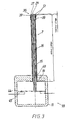
- FIG. 3 shows the internal structure and operation of the temperature sensor 7 shows that includes a sensor tube 15 and a sensor rod 16 disposed therein, wherein the sensor tube 15 and the sensor rod 16 different thermal expansion coefficients exhibit.
- a heating of the temperature sensor 7 therefore has a different longitudinal extent of the sensor tube 15 and the sensor rod 16 result.
- the end of the sensor rod 16 shifts in an upward direction and on during a heating process taking place in the region of the temperature sensor in the switching contact unit 44, 45 shown in FIG the contact piece 45 depressed contact spring 44 opens the closed switch contact.
- the sensor tube 15 is formed from a metal, in particular from a high-temperature-resistant metal, preferably from a CrNi alloy, the sensor rod 16 from a ceramic or quartz glass.
- the sensor tube 15 is provided at the switch contact end with a flange 19, with which it is supported against an insulating body 11 which surrounds the switch contact unit 44, 45. In this case, the sensor tube 15 is passed through an opening 49 of the insulating body 11.
- the end piece 38 of the sensor tube 15 is formed by a free end of the sensor tube 15 final tube cap 39 which is permanently connected to the sensor tube 15, wherein the one end of the sensor rod 16 on the inside of the sensor tube 15 facing inside the tube cap 39 is supported.
- the tube cap 39 is welded to the sensor tube 15, in particular laser-welded.
- the tube cap 39 is placed on the free end of the sensor tube 15 and then welded by means of laser application. The weld must withstand the pressure of the sensor rod 16 acting against the inside of the tube cap 39.
- the cross section of the sensor tube 15 is circular, but this can - in the context of the invention - as well as the cross section of the sensor rod 16 - be executed in any form
- the tube cap 39 in FIG. 3 is formed by a tube piece 28 whose inside diameter is larger than the outside diameter of the probe tube 15 and which is closed on one side by a flat end face 27 extending substantially normal to the tube axis.
- the tube piece 28 thus provided with the end face 27 may e.g. be formed from a deep-drawn sheet metal part.
- the end surface 27 of the pipe section 28 has a central, inwardly directed curvature, in particular in the form of a spherical cap 29, on which the sensor rod 16 is supported.
- the tube cap 39 is formed of the same metal as the sensor tube 15, in particular of a high temperature resistant metal, preferably of a CrNi alloy.
- the achievable due to an increase in temperature relative displacement between the sensor tube 15 and the sensor rod 16 depends on the different thermal expansion coefficients, from the temperature difference but also from the active for the expansion movement length of the combination sensor tube probe rod.
- the advantage of the tube cap 39 is the high active length of the temperature sensor 7 according to the invention, which is available for the temperature expansion, as shown in FIG. 3 can be seen. Since the tube cap 39 itself is subject to thermal expansion, its expansion adds to the thermal expansion of the sensor tube 15 and thus increases the difference in length compared to the thermal expansion of the sensor rod 16, which has a lower coefficient of thermal expansion.
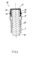
- FIG. 6 shows an embodiment of the temperature sensor 7 according to the invention, in which the tube cap 39 is formed by a tube piece 28 inserted into the free end of the probe tube 15 with a flat end surface 27.
- the free end of the probe tube 15 has an end region 37 a relative to the inner diameter of the sensor tube 15 "enlarged inner diameter, so that the inner diameter of the diameter-enlarged end portion 37 is greater than the outer diameter of the pipe section 28.
- Die Pipe cap 39 is inserted into the diameter-enlarged end portion 37 and welded or riveted at joints 40.
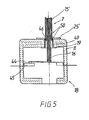
- the e.g. 3 insulation body 11 is preferably formed of a temperature-resistant ceramic, which must be immovably fixed to the radiator or other device so that a reproducible temperature measurement can be made possible.
- a support tab 25 is provided which has holes 47 for fixing the temperature sensor 7 on the radiator 1, which is effected by means of screws 30 which are driven through the holes 47 into the investment 4.
- the support bracket 25 is connected to a pipe seat 54 inserted into the opening 49, on which the sensor tube 15 is supported via a flange-shaped projection 19.
- the sensor tube 15 can run with great play or low backlash in the pipe seat 54 or be pressed into this or welded to it.
- the support tab 25 is welded to the pipe seat 54, so that the insulating body opening 49 surrounding wall portion of the insulating body 11 between the support bracket 25 and the pipe seat 54 is held.
- the pipe seat 54 is connected to the support bracket so that the pipe seat 54 against the insulating body 11 can neither slip nor tilt.
- the tubular seat 54 is tubular, whose outer diameter is smaller than the diameter of the insulating body opening 49 and whose inner diameter is larger than the diameter of the sensor tube 15 is formed.
- a pipe flange 55 is formed, which rests against the wall of the insulating body 11.
- the support tab 25 has an opening 46, wherein arranged in the area of the abutting surface with the pipe seat 54 weld point elevations 52, for example, are embossed, which simplify the welding of the pipe seat 54 with the support bracket 25.
- FIG 5 an embodiment of the invention is shown, in which the support tab 25 is welded directly to the supported on the opening 49 sensor tube 15, so that the Isolationskötper opening 49 surrounding wall portion of the insulating body 11 between the support bracket 25 and the sensor tube 15 is held is.
- the sensor tube 15 in the region of the insulating body opening 49 has a larger diameter than in its projecting area.
- the sensor tube 15 is again preferably made of a metal, in particular of a high-temperature resistant metal, preferably formed from a CrNi alloy and welded to weld point elevations 50 with the support bracket 25.
Landscapes
- Physics & Mathematics (AREA)
- Thermal Sciences (AREA)
- General Physics & Mathematics (AREA)
- Chemical & Material Sciences (AREA)
- Engineering & Computer Science (AREA)
- Ceramic Engineering (AREA)
- Measuring Temperature Or Quantity Of Heat (AREA)
- Thermally Actuated Switches (AREA)
- Investigating Or Analyzing Materials Using Thermal Means (AREA)
Applications Claiming Priority (2)
| Application Number | Priority Date | Filing Date | Title |
|---|---|---|---|
| AT0027902A AT411554B (de) | 2002-02-25 | 2002-02-25 | Temperaturfühler |
| EP03450018A EP1339260B1 (fr) | 2002-02-25 | 2003-01-17 | Capteur de température |
Related Parent Applications (2)
| Application Number | Title | Priority Date | Filing Date |
|---|---|---|---|
| EP03450018A Division EP1339260B1 (fr) | 2002-02-25 | 2003-01-17 | Capteur de température |
| EP03450018.1 Division | 2003-01-17 |
Publications (3)
| Publication Number | Publication Date |
|---|---|
| EP1887834A2 true EP1887834A2 (fr) | 2008-02-13 |
| EP1887834A3 EP1887834A3 (fr) | 2010-09-22 |
| EP1887834B1 EP1887834B1 (fr) | 2012-11-28 |
Family
ID=3670699
Family Applications (2)
| Application Number | Title | Priority Date | Filing Date |
|---|---|---|---|
| EP07021471A Expired - Lifetime EP1887834B1 (fr) | 2002-02-25 | 2003-01-17 | Sonde de température |
| EP03450018A Expired - Lifetime EP1339260B1 (fr) | 2002-02-25 | 2003-01-17 | Capteur de température |
Family Applications After (1)
| Application Number | Title | Priority Date | Filing Date |
|---|---|---|---|
| EP03450018A Expired - Lifetime EP1339260B1 (fr) | 2002-02-25 | 2003-01-17 | Capteur de température |
Country Status (5)
| Country | Link |
|---|---|
| US (1) | US6781505B2 (fr) |
| EP (2) | EP1887834B1 (fr) |
| AT (2) | AT411554B (fr) |
| DE (1) | DE50310686D1 (fr) |
| ES (1) | ES2404055T3 (fr) |
Families Citing this family (8)
| Publication number | Priority date | Publication date | Assignee | Title |
|---|---|---|---|---|
| EP1303169A1 (fr) * | 2001-10-15 | 2003-04-16 | Heraeus Sensor-Nite GmbH | Capteur de température utilisant un élément sensible ainsi que son utilisation |
| US20060037394A1 (en) * | 2004-08-20 | 2006-02-23 | Honeywell International, Inc. | High temperature sensor sleeve |
| IT1393070B1 (it) * | 2008-10-24 | 2012-04-11 | Worgas Bruciatori Srl | Termocoppia speciale per bruciatori |
| CN104111125B (zh) * | 2014-08-05 | 2017-04-12 | 苏州路之遥科技股份有限公司 | 一种温度传感器及温度调节器 |
| DE102014118206A1 (de) * | 2014-12-09 | 2016-06-09 | Endress + Hauser Wetzer Gmbh + Co. Kg | Temperaturfühler |
| DE102015002273A1 (de) | 2015-02-20 | 2016-08-25 | Siegfried Ulrich | Solartemperaturfühler für Regeleinheit zur Heizenergieeinsparung |
| US20170287664A1 (en) * | 2016-04-01 | 2017-10-05 | Intel Corporation | Thermally activated switch |
| US20220206516A1 (en) * | 2020-12-28 | 2022-06-30 | L'Air Liquide, Société Anonyme pour l'Etude et l'Exploitation des Procédés Georges Claude | Mechanical cryogenic temperature sensor and actuator |
Family Cites Families (27)
| Publication number | Priority date | Publication date | Assignee | Title |
|---|---|---|---|---|
| US1489116A (en) * | 1921-08-16 | 1924-04-01 | Commentry Fourchambault & Deca | Alloy for standards employed in expansion measurements and the applications thereof to measuring instruments |
| GB268645A (en) * | 1926-09-13 | 1927-04-07 | Robert Maclaren | Improvements in and connected with electrical control apparatus |
| US2185623A (en) * | 1937-10-08 | 1940-01-02 | Bryant Heater Co | Immersion type thermostat |
| US2548050A (en) * | 1949-09-28 | 1951-04-10 | Control Products Inc | Thermal switch |
| US2809523A (en) * | 1953-01-19 | 1957-10-15 | Herbert S Burling | Humidity or temperature differential measuring apparatus |
| US2705746A (en) * | 1953-10-30 | 1955-04-05 | Elsa L Strange | Apparatus for the improvements in thermostats or heat controls |
| US2777919A (en) * | 1954-01-11 | 1957-01-15 | Kidde & Co Walter | Thermostatic switch |
| US2705747A (en) * | 1954-01-28 | 1955-04-05 | Elsa L Strange | Temperature control instruments |
| DE1117332B (de) | 1958-03-20 | 1961-11-16 | Pruefgeraete Werk Medingen Veb | Temperaturregler mit Hilfsenergie |
| US2990716A (en) * | 1958-11-04 | 1961-07-04 | Texas Instruments Inc | Thermally responsive actuator |
| US3130354A (en) * | 1959-02-20 | 1964-04-21 | Herbert S Burling | Temperature control |
| US3004123A (en) * | 1960-04-28 | 1961-10-10 | Kenneth B Cannon | Thermally responsive actuator |
| US3158718A (en) * | 1961-06-05 | 1964-11-24 | Texas Instruments Inc | Motion amplication switch means |
| US3282108A (en) * | 1963-09-24 | 1966-11-01 | Robertshaw Controls Co | Temperature sensor |
| US3310647A (en) * | 1965-03-22 | 1967-03-21 | Therm O Disc Inc | Temperature sensing probe with means for maintaining the tubular element in engagement with a ceramic rod member |
| US3498133A (en) | 1966-09-30 | 1970-03-03 | Nippon Carbon Co Ltd | Apparatus for measuring high temperatures |
| US3594675A (en) * | 1969-05-28 | 1971-07-20 | Robertshaw Controls Co | Temperature-sensing probe |
| US3842675A (en) * | 1972-12-26 | 1974-10-22 | Ohio Thermometer Co | Thermometer |
| SE419806B (sv) * | 1973-08-30 | 1981-08-24 | Ego Elektro Blanc & Fischer | Elektrisk stromstellare |
| AT386714B (de) * | 1983-07-07 | 1988-10-10 | Electrovac | Vorrichtung zur heissanzeige und zur regelung bzw. begrenzung der temperatur von strahlungsbzw. kontaktheizkoerpern von elektrischen kochgeraeten |
| AT382708B (de) | 1983-07-07 | 1987-04-10 | Electrovac | Vorrichtung zur regelung bzw. begrenzung wenigstens eines temperaturwertes bzw. eines temperaturbereiches von strahlungs- bzw. kontaktheizkoerpern |
| DE3540414A1 (de) * | 1985-11-14 | 1987-05-21 | Ego Elektro Blanc & Fischer | Temperaturbegrenzer |
| DE3705260A1 (de) * | 1987-02-19 | 1988-09-01 | Ego Elektro Blanc & Fischer | Temperaturbegrenzer |
| DE4029351A1 (de) * | 1990-09-15 | 1992-03-19 | Ego Elektro Blanc & Fischer | Temperaturfuehler |
| GB2278237B (en) * | 1993-05-21 | 1996-09-04 | Ceramaspeed Ltd | Thermal cut-out device |
| US5294907A (en) * | 1993-06-22 | 1994-03-15 | Robertshaw Controls Company | Control device, parts therefor and methods of making the same |
| DE19724820A1 (de) * | 1997-06-12 | 1998-12-17 | Ego Elektro Geraetebau Gmbh | Schaltglied für Elektrogeräte, wie Elektrowärmegeräte |
-
2002
- 2002-02-25 AT AT0027902A patent/AT411554B/de not_active IP Right Cessation
-
2003
- 2003-01-17 EP EP07021471A patent/EP1887834B1/fr not_active Expired - Lifetime
- 2003-01-17 AT AT03450018T patent/ATE413084T1/de not_active IP Right Cessation
- 2003-01-17 ES ES07021471T patent/ES2404055T3/es not_active Expired - Lifetime
- 2003-01-17 EP EP03450018A patent/EP1339260B1/fr not_active Expired - Lifetime
- 2003-01-17 DE DE50310686T patent/DE50310686D1/de not_active Expired - Lifetime
- 2003-02-21 US US10/371,605 patent/US6781505B2/en not_active Expired - Lifetime
Also Published As
| Publication number | Publication date |
|---|---|
| EP1887834B1 (fr) | 2012-11-28 |
| EP1339260B1 (fr) | 2008-10-29 |
| ATA2792002A (de) | 2003-07-15 |
| ES2404055T3 (es) | 2013-05-23 |
| US20030161381A1 (en) | 2003-08-28 |
| EP1887834A3 (fr) | 2010-09-22 |
| DE50310686D1 (de) | 2008-12-11 |
| AT411554B (de) | 2004-02-25 |
| EP1339260A1 (fr) | 2003-08-27 |
| US6781505B2 (en) | 2004-08-24 |
| ATE413084T1 (de) | 2008-11-15 |
Similar Documents
| Publication | Publication Date | Title |
|---|---|---|
| EP0141923B1 (fr) | Limiteur de température pour plaques de cuisson en vitro-céramique | |
| EP0279368B1 (fr) | Limiteur de température | |
| DE102005060217B4 (de) | Ventil | |
| EP1887834B1 (fr) | Sonde de température | |
| EP1569257B1 (fr) | Capteur de température | |
| DE19909106C2 (de) | Temperaturkompensierte piezoelektrische Aktoreinheit | |
| EP1223597B1 (fr) | Limiteur de température | |
| AT409680B (de) | Temperaturbegrenzer | |
| EP0394693A2 (fr) | Appareil de commutation de température | |
| DE3628174C2 (fr) | ||
| DE3333645A1 (de) | Temperaturbegrenzer fuer eine glaskeramikkocheinheit | |
| EP0377169B1 (fr) | Appareil interrupteur | |
| DE2117323C3 (de) | Temperaturschalter | |
| EP0523645B1 (fr) | Interrupteur électrique | |
| DE19925367A1 (de) | Temperatursensor | |
| DE3219517C2 (de) | Temperaturreglerschalter | |
| AT500445B1 (de) | Temperaturfühler | |
| DE3508585A1 (de) | Doppeltemperaturthermostat | |
| DE2422624A1 (de) | Temperaturbegrenzer | |
| EP0285086A2 (fr) | Appareil de commande de puissance | |
| DE2414812B2 (de) | Ausdehnungsdose | |
| DE3604021A1 (de) | Thermostat | |
| EP0481355B1 (fr) | Appareil interrupteur comprenant un dispositif pour commander une influence charactéristiq ambiante | |
| DE2219451B2 (de) | Raumtemperaturregler | |
| DE19808405A1 (de) | Strahlrohranordnung |
Legal Events
| Date | Code | Title | Description |
|---|---|---|---|
| PUAI | Public reference made under article 153(3) epc to a published international application that has entered the european phase |
Free format text: ORIGINAL CODE: 0009012 |
|
| AC | Divisional application: reference to earlier application |
Ref document number: 1339260 Country of ref document: EP Kind code of ref document: P |
|
| AK | Designated contracting states |
Kind code of ref document: A2 Designated state(s): AT BE BG CH CY CZ DE DK EE ES FI FR GB GR HU IE IT LI LU MC NL PT SE SI SK TR |
|
| AX | Request for extension of the european patent |
Extension state: AL LT LV MK RO |
|
| RIC1 | Information provided on ipc code assigned before grant |
Ipc: G01K 1/16 20060101ALI20090303BHEP Ipc: G01K 1/12 20060101AFI20090303BHEP |
|
| PUAL | Search report despatched |
Free format text: ORIGINAL CODE: 0009013 |
|
| AK | Designated contracting states |
Kind code of ref document: A3 Designated state(s): AT BE BG CH CY CZ DE DK EE ES FI FR GB GR HU IE IT LI LU MC NL PT SE SI SK TR |
|
| AX | Request for extension of the european patent |
Extension state: AL LT LV MK RO |
|
| RIC1 | Information provided on ipc code assigned before grant |
Ipc: G01K 5/50 20060101ALI20100819BHEP Ipc: G01K 3/00 20060101ALI20100819BHEP Ipc: G01K 1/16 20060101ALI20100819BHEP Ipc: G01K 1/12 20060101AFI20090303BHEP |
|
| 17P | Request for examination filed |
Effective date: 20110318 |
|
| AKX | Designation fees paid |
Designated state(s): AT BE BG CH CY CZ DE DK EE ES FI FR GB GR HU IE IT LI LU MC NL PT SE SI SK TR |
|
| AXX | Extension fees paid |
Extension state: RO Payment date: 20110318 Extension state: MK Payment date: 20110318 Extension state: LV Payment date: 20110318 Extension state: LT Payment date: 20110318 Extension state: AL Payment date: 20110318 |
|
| RAP1 | Party data changed (applicant data changed or rights of an application transferred) |
Owner name: CERAMASPEED INC. |
|
| DAX | Request for extension of the european patent (deleted) | ||
| GRAP | Despatch of communication of intention to grant a patent |
Free format text: ORIGINAL CODE: EPIDOSNIGR1 |
|
| GRAS | Grant fee paid |
Free format text: ORIGINAL CODE: EPIDOSNIGR3 |
|
| GRAA | (expected) grant |
Free format text: ORIGINAL CODE: 0009210 |
|
| AC | Divisional application: reference to earlier application |
Ref document number: 1339260 Country of ref document: EP Kind code of ref document: P |
|
| AK | Designated contracting states |
Kind code of ref document: B1 Designated state(s): AT BE BG CH CY CZ DE DK EE ES FI FR GB GR HU IE IT LI LU MC NL PT SE SI SK TR |
|
| REG | Reference to a national code |
Ref country code: GB Ref legal event code: FG4D Free format text: NOT ENGLISH |
|
| REG | Reference to a national code |
Ref country code: CH Ref legal event code: EP |
|
| REG | Reference to a national code |
Ref country code: AT Ref legal event code: REF Ref document number: 586419 Country of ref document: AT Kind code of ref document: T Effective date: 20121215 |
|
| REG | Reference to a national code |
Ref country code: IE Ref legal event code: FG4D Free format text: LANGUAGE OF EP DOCUMENT: GERMAN |
|
| REG | Reference to a national code |
Ref country code: DE Ref legal event code: R096 Ref document number: 50314599 Country of ref document: DE Effective date: 20130124 |
|
| REG | Reference to a national code |
Ref country code: NL Ref legal event code: VDEP Effective date: 20121128 |
|
| PG25 | Lapsed in a contracting state [announced via postgrant information from national office to epo] |
Ref country code: SE Free format text: LAPSE BECAUSE OF FAILURE TO SUBMIT A TRANSLATION OF THE DESCRIPTION OR TO PAY THE FEE WITHIN THE PRESCRIBED TIME-LIMIT Effective date: 20121128 Ref country code: FI Free format text: LAPSE BECAUSE OF FAILURE TO SUBMIT A TRANSLATION OF THE DESCRIPTION OR TO PAY THE FEE WITHIN THE PRESCRIBED TIME-LIMIT Effective date: 20121128 |
|
| REG | Reference to a national code |
Ref country code: ES Ref legal event code: FG2A Ref document number: 2404055 Country of ref document: ES Kind code of ref document: T3 Effective date: 20130523 |
|
| PG25 | Lapsed in a contracting state [announced via postgrant information from national office to epo] |
Ref country code: PT Free format text: LAPSE BECAUSE OF FAILURE TO SUBMIT A TRANSLATION OF THE DESCRIPTION OR TO PAY THE FEE WITHIN THE PRESCRIBED TIME-LIMIT Effective date: 20130328 Ref country code: SI Free format text: LAPSE BECAUSE OF FAILURE TO SUBMIT A TRANSLATION OF THE DESCRIPTION OR TO PAY THE FEE WITHIN THE PRESCRIBED TIME-LIMIT Effective date: 20121128 Ref country code: GR Free format text: LAPSE BECAUSE OF FAILURE TO SUBMIT A TRANSLATION OF THE DESCRIPTION OR TO PAY THE FEE WITHIN THE PRESCRIBED TIME-LIMIT Effective date: 20130301 |
|
| BERE | Be: lapsed |
Owner name: CERAMASPEED INC. Effective date: 20130131 |
|
| PG25 | Lapsed in a contracting state [announced via postgrant information from national office to epo] |
Ref country code: BG Free format text: LAPSE BECAUSE OF FAILURE TO SUBMIT A TRANSLATION OF THE DESCRIPTION OR TO PAY THE FEE WITHIN THE PRESCRIBED TIME-LIMIT Effective date: 20130228 Ref country code: DK Free format text: LAPSE BECAUSE OF FAILURE TO SUBMIT A TRANSLATION OF THE DESCRIPTION OR TO PAY THE FEE WITHIN THE PRESCRIBED TIME-LIMIT Effective date: 20121128 Ref country code: SK Free format text: LAPSE BECAUSE OF FAILURE TO SUBMIT A TRANSLATION OF THE DESCRIPTION OR TO PAY THE FEE WITHIN THE PRESCRIBED TIME-LIMIT Effective date: 20121128 Ref country code: EE Free format text: LAPSE BECAUSE OF FAILURE TO SUBMIT A TRANSLATION OF THE DESCRIPTION OR TO PAY THE FEE WITHIN THE PRESCRIBED TIME-LIMIT Effective date: 20121128 Ref country code: CY Free format text: LAPSE BECAUSE OF FAILURE TO SUBMIT A TRANSLATION OF THE DESCRIPTION OR TO PAY THE FEE WITHIN THE PRESCRIBED TIME-LIMIT Effective date: 20121128 Ref country code: CZ Free format text: LAPSE BECAUSE OF FAILURE TO SUBMIT A TRANSLATION OF THE DESCRIPTION OR TO PAY THE FEE WITHIN THE PRESCRIBED TIME-LIMIT Effective date: 20121128 |
|
| PG25 | Lapsed in a contracting state [announced via postgrant information from national office to epo] |
Ref country code: MC Free format text: LAPSE BECAUSE OF NON-PAYMENT OF DUE FEES Effective date: 20130131 Ref country code: IT Free format text: LAPSE BECAUSE OF FAILURE TO SUBMIT A TRANSLATION OF THE DESCRIPTION OR TO PAY THE FEE WITHIN THE PRESCRIBED TIME-LIMIT Effective date: 20121128 Ref country code: NL Free format text: LAPSE BECAUSE OF FAILURE TO SUBMIT A TRANSLATION OF THE DESCRIPTION OR TO PAY THE FEE WITHIN THE PRESCRIBED TIME-LIMIT Effective date: 20121128 |
|
| REG | Reference to a national code |
Ref country code: CH Ref legal event code: PL |
|
| PLBE | No opposition filed within time limit |
Free format text: ORIGINAL CODE: 0009261 |
|
| STAA | Information on the status of an ep patent application or granted ep patent |
Free format text: STATUS: NO OPPOSITION FILED WITHIN TIME LIMIT |
|
| REG | Reference to a national code |
Ref country code: IE Ref legal event code: MM4A |
|
| PG25 | Lapsed in a contracting state [announced via postgrant information from national office to epo] |
Ref country code: LI Free format text: LAPSE BECAUSE OF NON-PAYMENT OF DUE FEES Effective date: 20130131 Ref country code: BE Free format text: LAPSE BECAUSE OF NON-PAYMENT OF DUE FEES Effective date: 20130131 Ref country code: CH Free format text: LAPSE BECAUSE OF NON-PAYMENT OF DUE FEES Effective date: 20130131 |
|
| 26N | No opposition filed |
Effective date: 20130829 |
|
| REG | Reference to a national code |
Ref country code: DE Ref legal event code: R097 Ref document number: 50314599 Country of ref document: DE Effective date: 20130829 |
|
| PG25 | Lapsed in a contracting state [announced via postgrant information from national office to epo] |
Ref country code: IE Free format text: LAPSE BECAUSE OF NON-PAYMENT OF DUE FEES Effective date: 20130117 |
|
| PG25 | Lapsed in a contracting state [announced via postgrant information from national office to epo] |
Ref country code: TR Free format text: LAPSE BECAUSE OF FAILURE TO SUBMIT A TRANSLATION OF THE DESCRIPTION OR TO PAY THE FEE WITHIN THE PRESCRIBED TIME-LIMIT Effective date: 20121128 |
|
| PG25 | Lapsed in a contracting state [announced via postgrant information from national office to epo] |
Ref country code: HU Free format text: LAPSE BECAUSE OF FAILURE TO SUBMIT A TRANSLATION OF THE DESCRIPTION OR TO PAY THE FEE WITHIN THE PRESCRIBED TIME-LIMIT; INVALID AB INITIO Effective date: 20030117 Ref country code: LU Free format text: LAPSE BECAUSE OF NON-PAYMENT OF DUE FEES Effective date: 20130117 |
|
| REG | Reference to a national code |
Ref country code: FR Ref legal event code: PLFP Year of fee payment: 14 |
|
| REG | Reference to a national code |
Ref country code: FR Ref legal event code: PLFP Year of fee payment: 15 |
|
| REG | Reference to a national code |
Ref country code: FR Ref legal event code: PLFP Year of fee payment: 16 |
|
| REG | Reference to a national code |
Ref country code: DE Ref legal event code: R082 Ref document number: 50314599 Country of ref document: DE Representative=s name: DREISS PATENTANWAELTE PARTG MBB, DE Ref country code: DE Ref legal event code: R081 Ref document number: 50314599 Country of ref document: DE Owner name: EIKA, S.COOP, ETXEBARRIA, ES Free format text: FORMER OWNER: CERAMASPEED INC., MARYVILLE, TENN., US |
|
| REG | Reference to a national code |
Ref country code: ES Ref legal event code: PC2A Owner name: EIKA, S.COOP. Effective date: 20200323 |
|
| PGFP | Annual fee paid to national office [announced via postgrant information from national office to epo] |
Ref country code: DE Payment date: 20200129 Year of fee payment: 18 Ref country code: AT Payment date: 20200121 Year of fee payment: 18 Ref country code: GB Payment date: 20200127 Year of fee payment: 18 |
|
| PGFP | Annual fee paid to national office [announced via postgrant information from national office to epo] |
Ref country code: FR Payment date: 20200127 Year of fee payment: 18 |
|
| REG | Reference to a national code |
Ref country code: AT Ref legal event code: PC Ref document number: 586419 Country of ref document: AT Kind code of ref document: T Owner name: EIKA, S.COOP, ES Effective date: 20200629 |
|
| PGFP | Annual fee paid to national office [announced via postgrant information from national office to epo] |
Ref country code: ES Payment date: 20210204 Year of fee payment: 19 |
|
| REG | Reference to a national code |
Ref country code: DE Ref legal event code: R119 Ref document number: 50314599 Country of ref document: DE |
|
| REG | Reference to a national code |
Ref country code: AT Ref legal event code: MM01 Ref document number: 586419 Country of ref document: AT Kind code of ref document: T Effective date: 20210117 |
|
| GBPC | Gb: european patent ceased through non-payment of renewal fee |
Effective date: 20210117 |
|
| PG25 | Lapsed in a contracting state [announced via postgrant information from national office to epo] |
Ref country code: AT Free format text: LAPSE BECAUSE OF NON-PAYMENT OF DUE FEES Effective date: 20210117 Ref country code: FR Free format text: LAPSE BECAUSE OF NON-PAYMENT OF DUE FEES Effective date: 20210131 |
|
| PG25 | Lapsed in a contracting state [announced via postgrant information from national office to epo] |
Ref country code: GB Free format text: LAPSE BECAUSE OF NON-PAYMENT OF DUE FEES Effective date: 20210117 Ref country code: DE Free format text: LAPSE BECAUSE OF NON-PAYMENT OF DUE FEES Effective date: 20210803 |
|
| REG | Reference to a national code |
Ref country code: ES Ref legal event code: FD2A Effective date: 20230227 |
|
| PG25 | Lapsed in a contracting state [announced via postgrant information from national office to epo] |
Ref country code: ES Free format text: LAPSE BECAUSE OF NON-PAYMENT OF DUE FEES Effective date: 20220118 |