EP1887318A2 - Bildprozessor und Bildverarbeitungsverfahren zur Objekterkennung und zur Detektion einer Entfernung zu diesem Objekt - Google Patents
Bildprozessor und Bildverarbeitungsverfahren zur Objekterkennung und zur Detektion einer Entfernung zu diesem Objekt Download PDFInfo
- Publication number
- EP1887318A2 EP1887318A2 EP07015732A EP07015732A EP1887318A2 EP 1887318 A2 EP1887318 A2 EP 1887318A2 EP 07015732 A EP07015732 A EP 07015732A EP 07015732 A EP07015732 A EP 07015732A EP 1887318 A2 EP1887318 A2 EP 1887318A2
- Authority
- EP
- European Patent Office
- Prior art keywords
- image
- irradiation
- pickup
- processor
- picked
- Prior art date
- Legal status (The legal status is an assumption and is not a legal conclusion. Google has not performed a legal analysis and makes no representation as to the accuracy of the status listed.)
- Ceased
Links
- 238000003672 processing method Methods 0.000 title claims description 6
- 230000001678 irradiating effect Effects 0.000 claims description 14
- 230000001360 synchronised effect Effects 0.000 claims description 6
- 238000004364 calculation method Methods 0.000 claims description 2
- 238000010586 diagram Methods 0.000 description 8
- 230000002093 peripheral effect Effects 0.000 description 8
- 238000005516 engineering process Methods 0.000 description 5
- 238000000034 method Methods 0.000 description 4
- 239000000284 extract Substances 0.000 description 3
- 230000003247 decreasing effect Effects 0.000 description 2
- 238000001228 spectrum Methods 0.000 description 2
- 238000004458 analytical method Methods 0.000 description 1
- QSHDDOUJBYECFT-UHFFFAOYSA-N mercury Chemical compound [Hg] QSHDDOUJBYECFT-UHFFFAOYSA-N 0.000 description 1
- 229910052753 mercury Inorganic materials 0.000 description 1
- 238000012986 modification Methods 0.000 description 1
- 230000004048 modification Effects 0.000 description 1
Images





Classifications
-
- G—PHYSICS
- G01—MEASURING; TESTING
- G01C—MEASURING DISTANCES, LEVELS OR BEARINGS; SURVEYING; NAVIGATION; GYROSCOPIC INSTRUMENTS; PHOTOGRAMMETRY OR VIDEOGRAMMETRY
- G01C3/00—Measuring distances in line of sight; Optical rangefinders
- G01C3/02—Details
- G01C3/06—Use of electric means to obtain final indication
- G01C3/08—Use of electric radiation detectors
-
- G—PHYSICS
- G01—MEASURING; TESTING
- G01B—MEASURING LENGTH, THICKNESS OR SIMILAR LINEAR DIMENSIONS; MEASURING ANGLES; MEASURING AREAS; MEASURING IRREGULARITIES OF SURFACES OR CONTOURS
- G01B11/00—Measuring arrangements characterised by the use of optical techniques
- G01B11/24—Measuring arrangements characterised by the use of optical techniques for measuring contours or curvatures
- G01B11/25—Measuring arrangements characterised by the use of optical techniques for measuring contours or curvatures by projecting a pattern, e.g. one or more lines, moiré fringes on the object
- G01B11/2513—Measuring arrangements characterised by the use of optical techniques for measuring contours or curvatures by projecting a pattern, e.g. one or more lines, moiré fringes on the object with several lines being projected in more than one direction, e.g. grids, patterns
-
- G—PHYSICS
- G01—MEASURING; TESTING
- G01C—MEASURING DISTANCES, LEVELS OR BEARINGS; SURVEYING; NAVIGATION; GYROSCOPIC INSTRUMENTS; PHOTOGRAMMETRY OR VIDEOGRAMMETRY
- G01C11/00—Photogrammetry or videogrammetry, e.g. stereogrammetry; Photographic surveying
-
- G—PHYSICS
- G01—MEASURING; TESTING
- G01C—MEASURING DISTANCES, LEVELS OR BEARINGS; SURVEYING; NAVIGATION; GYROSCOPIC INSTRUMENTS; PHOTOGRAMMETRY OR VIDEOGRAMMETRY
- G01C11/00—Photogrammetry or videogrammetry, e.g. stereogrammetry; Photographic surveying
- G01C11/04—Interpretation of pictures
- G01C11/06—Interpretation of pictures by comparison of two or more pictures of the same area
- G01C11/12—Interpretation of pictures by comparison of two or more pictures of the same area the pictures being supported in the same relative position as when they were taken
- G01C11/14—Interpretation of pictures by comparison of two or more pictures of the same area the pictures being supported in the same relative position as when they were taken with optical projection
-
- G—PHYSICS
- G01—MEASURING; TESTING
- G01S—RADIO DIRECTION-FINDING; RADIO NAVIGATION; DETERMINING DISTANCE OR VELOCITY BY USE OF RADIO WAVES; LOCATING OR PRESENCE-DETECTING BY USE OF THE REFLECTION OR RERADIATION OF RADIO WAVES; ANALOGOUS ARRANGEMENTS USING OTHER WAVES
- G01S17/00—Systems using the reflection or reradiation of electromagnetic waves other than radio waves, e.g. lidar systems
- G01S17/88—Lidar systems specially adapted for specific applications
- G01S17/89—Lidar systems specially adapted for specific applications for mapping or imaging
-
- G—PHYSICS
- G01—MEASURING; TESTING
- G01S—RADIO DIRECTION-FINDING; RADIO NAVIGATION; DETERMINING DISTANCE OR VELOCITY BY USE OF RADIO WAVES; LOCATING OR PRESENCE-DETECTING BY USE OF THE REFLECTION OR RERADIATION OF RADIO WAVES; ANALOGOUS ARRANGEMENTS USING OTHER WAVES
- G01S17/00—Systems using the reflection or reradiation of electromagnetic waves other than radio waves, e.g. lidar systems
- G01S17/88—Lidar systems specially adapted for specific applications
- G01S17/93—Lidar systems specially adapted for specific applications for anti-collision purposes
- G01S17/931—Lidar systems specially adapted for specific applications for anti-collision purposes of land vehicles
Definitions
- the present invention relates to an image processor and an image processing method. Based on an image picked up by an image pickup part, the image processor and the image processing method can recognize a peripheral object and sense a distance to the peripheral object.
- Conventionally known technology includes a camera which is set in a vehicle.
- the camera picks up a peripheral image of the vehicle. Based on the thus picked up image, the conventional technology senses a peripheral object and a distance to the peripheral object.
- 2003-169251 JP2003169251 ⁇ having family including US6858827 (B2 ) and US2003052252 (A ) ⁇ discloses a technology which alternately repeats i) irradiating an image pickup area of the camera and ii) non-irradiating the same, thus 1) sensing a peripheral object based on an image (object sensing image) obtained during the non-irradiating and 2) calculating a distance to the peripheral object based on an image (distance sensing image) obtained during the irradiating.
- the conventional technology in JP2003169251 for alternately obtaining the object sensing image and the distance sensing image fails to serially sense the peripheral object. Therefore, the conventional technology, as the case may be, erroneously senses (recognizes) an object as a different object even when the thus sensed (recognized) object is the same object.
- an image processor comprising: an image pickup part configured to pick up a pickup image of a certain area; an irradiator configured to irradiate at least a part of the certain area for the pickup image picked up by the image pickup part; an extractor configured to extract, as an irradiation image, a light irradiated from the irradiator, the irradiation image being extracted from the pickup image picked up by the image pickup part; an image generating part configured to generate an irradiation removed image which is obtained by removing the irradiation image from the pickup image; an object recognizer configured to recognize an object in the certain area, based on the irradiation removed image generated by the image generating part; and a distance sensor configured to sense a distance to the object recognized by the object recognizer.
- an image processing method comprising: picking up a pickup image of a certain area; irradiating at least a part of the certain area for the pickup image picked up by the picking up operation; extracting, as an irradiation image, a light irradiated from the irradiating operation, the irradiation image being extracted from the pickup image picked up by the picking up operation; generating an irradiation removed image which is obtained by removing the irradiation image from the pickup image; recognizing an object in the certain area, based on the irradiation removed image generated by the generating operation; and sensing a distance to the object recognized by the recognizing operation.
- an image processor comprising: means for picking up a pickup image of a certain area; means for irradiating at least a part of the certain area for the pickup image picked up by the picking up means; means for extracting, as an irradiation image, a light irradiated from the irradiating means, the irradiation image being extracted from the pickup image picked up by the picking up means; means for generating an irradiation removed image which is obtained by removing the irradiation image from the pickup image; means for recognizing an object in the certain area, based on the irradiation removed image generated by the generating means; and means for sensing a distance to the object recognized by the recognizing means.
- the present invention eliminates the need for alternately obtaining an object sensing image and a distance sensing image, allowing a serial sensing (recognizing) of the object.
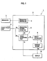
- FIG. 1 A block diagram of the image processor is to be explained referring to Fig. 1, according to a first embodiment of the present invention.
- an image processor 1 mainly includes an irradiator 3, an irradiation controller 4, an image pickup part 5, an irradiation pattern extractor 6, an image generating part 7, an object recognizer 8, a distance sensor 9, a display 10, and an administrative processor 2.
- the administrative processor 2 administratively controls each of the above elements of the image processor 1.
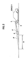
- the irradiator 3 sends an irradiation pattern P necessary for sensing a distance D between an object 15 and a vehicle V, as shown in Fig. 2.
- wavelength of an irradiated light is not especially limited, therefore a visible light or an infrared light can be used according to situations.
- the image pickup area H is defined by two image pickup patterns P', P'.
- the irradiation controller 4 controls period of the irradiation pattern P.
- the above certain time interval of the on-off control is, for example, 33 msec (shortest) when an image pickup element for an ordinary video camera is used as the image pickup part 5.
- the certain time interval of the on-off control is, however, to be determined based on i) travel speed of the object 15 to be calculated or ii) frequency spectrum of external light.
- the image pickup part 5 picks up an image of the image pickup area H including the irradiation pattern P sent from the irradiator 3.
- the thus picked up image serves as a distance sensing image 5A (otherwise referred to as "pick up image” or "original image”).
- the image pickup part 5 outputs the distance sensing image 5A to the irradiation pattern extractor 6 and the image generating part 7 so that the distance sensing image 5A is outputted to the distance sensor 9.
- the irradiation pattern extractor 6 extracts an image (hereinafter, referred to as "irradiation image 6A") corresponding to the irradiation pattern P. Then, the irradiation pattern extractor 6 inputs the thus extracted irradiation image 6A to the image generating part 7.
- the distance sensing image 5A picked up by the image pickup part 5 has various space frequencies, as shown in Fig. 3A.
- the irradiation controller 4 makes the on-off control of the irradiator 3 at the certain time interval ⁇ for example, 33 msec (shortest) as set forth above ⁇ , the irradiation pattern P is caused to have a certain time interval (hereinafter, referred to as "irradiation period").
- the irradiation period is, for example, 33 msec (shortest) when an image pickup element for an ordinary video camera is used as the image pickup part 5.
- the irradiation period is, however, to be determined based on i) travel speed of the object 15 to be calculated or ii) frequency spectrum of external light. Then, an image signal having a period substantially equal to the irradiation period is extracted using a band pass filter, thereby extracting the irradiation image 6A only, as shown in Fig. 3B.
- the object recognizer 8 recognizes (senses) the object 15 in the object sensing image 7A inputted from the image generating part 7.
- the object sensing image 7A and the distance sensing image 5A are drawn by a luminance which is obtained based on a luminance distribution or a temperature distribution ahead of the vehicle V.
- the object 15 ahead of the vehicle V is drawn with a color or hue according to the luminance or temperature of the object 15.
- the object recognizer 8 recognizes the object 15.
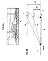
- the distance sensor 9 measures the distance D (from the vehicle V [original point 0] to the object 15) recognized by the object recognizer 8. As shown in Fig. 5A, the distance D from an original point 0 to a point P1 where the irradiation pattern P is irradiated in the distance sensing image 5A is to be calculated.
- Fig. 5B shows the following parameters:
- the distance D from the original point 0 to the point P1 can be calculated based on the above known parameters.
- the distance sensor 9 outputs distance sensing data 9A to the display 10, so as to display the distance D on the object sensing image 7A to be displayed on the display 10.
- the display 10 is a typical motor for displaying the object sensing image 7A inputted from the image generating part 7 and the distance sensing data 9A inputted from the distance sensor 9.
- the administrative processor 2 makes the following operations:
- FIG. 6 a block diagram of the image processor 1 is to be explained referring to Fig. 6, according to a second embodiment of the present invention.
- explanations about structural elements like those of the image processor 1 according to the first embodiment are to be omitted, therefore different structural elements only are to be explained.
- the image processor 1 mainly includes the irradiator 3, the irradiation controller 4, the image pickup part 5, the irradiation pattern extractor 6, the image generating part 7, the object recognizer 8, the distance sensor 9, the display 10, a frequency analyzer 11, and the administrative processor 2.
- the administrative processor 2 administratively controls each of the above elements of the image processor 1.
- the irradiation pattern extractor 6 according to the first embodiment of the present invention uses the band pass filter that is fixed. Meanwhile, the irradiation pattern extractor 6 according to the second embodiment of the present invention uses a variable band pass filter capable of varying extracted frequency bands.
- the frequency analyzer 11 analyzes frequency in the distance sensing image 5A inputted to the image pickup part 5, and then inputs an analysis result 11A to the irradiation controller 4 and the irradiation pattern extractor 6.
- the distance sensing image 5A (or "original image"), as the case may be, includes the external light which is caused by i) a light from a commercial alternating current power source of 50 Hz or 60 Hz, ii) a mercury lamp lit by high frequency control, and the like.
- the band pass filter of the irradiation pattern extractor 6 cannot distinguish the irradiation pattern P (irradiation image 6A) from the external light. From the distance sensing image 5A, the irradiation pattern extractor 6 removes both the irradiation pattern P (irradiation image 6A) and the external light, thus making it difficult to obtain the object sensing image 7A.
- the frequency analyzer 11 allows the irradiation controller 4 to control such that the irradiation pattern P of the irradiator 3 is set to have the irradiation period different from a period of a frequency component (i.e., lightening period) of the external light. Moreover, the frequency analyzer 11 sets the variable band pass filter of the irradiation pattern extractor 6 in conformity with the irradiation period of the irradiation pattern P. The above operations of the frequency analyzer 11 allow the irradiation pattern extractor 6 to extract the irradiation pattern P (irradiation image 6A), even when the external light having the lightening period coinciding with the irradiation period is included in the distance sensing image 5A.
- a synchronous detector 6X for the irradiation pattern extractor 6 such that a signal synchronous with the irradiation period is inputted from the irradiation controller 4 to the synchronous detector 6X can likewise extract the irradiation pattern P (irradiation image 6A).
- FIG. 7 a block diagram of the image processor 1 is to be explained referring to Fig. 7, according to a third embodiment of the present invention.
- explanations about structural elements like those of the image processor 1 according to the first and second embodiments are to be omitted, therefore different structural elements only are to be explained.
- the image processor 1 mainly includes the irradiator 3, the irradiation controller 4, the image pickup part 5, the irradiation pattern extractor 6, the image generating part 7, the object recognizer 8, the distance sensor 9, the display 10, a luminance determiner 12, and the administrative processor 2.
- the administrative processor 2 administratively controls each of the above elements of the image processor 1.
- the luminance determiner 12 determines whether a per-pixel luminance of the distance sensing image 5A inputted from the image pickup part 5 is larger or smaller than a certain luminance, then inputs a per-pixel luminance determination result 12A to the image generating part 7.
- the above certain luminance is, for example, about 30 (threshold) at 8 bit (gradation) when an image having SN ratio (signal-noise ratio) of about 20 dB at 8 bit (gradation) is picked up.
- the image generating part 7 forbids the difference operation of a part of an image signal which part causes a per-pixel difference result of less than or equal to a noise level.
- the luminance determiner 12 and image generating part 7 are to be set forth.
- the distance sensing image 5A obtained by the image pickup part 5 is dark. Removing the irradiation image 6A from the distance sensing image 5A by the difference operation without a specific countermeasure may cause to the image signal a part less than or equal to the noise level.
- the object sensing image 7A on the display 10 has a black collapse.
- the image generating part 7 is configured to make the following operations:
- step S1 the distance sensing image 5A picked up by the image pickup part 5 is outputted to each of the irradiation pattern extractor 6 and the luminance determiner 12.
- the irradiation pattern extractor 6 extracts the irradiation image 6A of the irradiation pattern P.
- the luminance determiner 12 determines whether the per-pixel luminance of the distance sensing image 5A is larger or smaller than the certain luminance.
- the image generating part 7 implements the difference operation on the per-pixel luminance larger than the certain luminance.
- the image generating part 7 generates the object sensing image 7A from the pixels subjected to the difference operation and from the pixels not subjected to the difference operation.
- the image generating part 7 is configured to make the following operations:
- FIG. 9 a block diagram of the image processor 1 is to be explained referring to Fig. 9, according to a fourth embodiment of the present invention.
- explanations about structural elements like those of the image processor 1 according to the first to third embodiments are to be omitted, therefore different structural elements only are to be explained.
- the image processor 1 mainly includes the irradiator 3, the irradiation controller 4, the image pickup part 5, the irradiation pattern extractor 6, the image generating part 7, the object recognizer 8, the distance sensor 9, the display 10, a moving amount corrector 13, and the administrative processor 2.
- the administrative processor 2 administratively controls each of the above elements of the image processor 1.
- the moving amount corrector 13 is configured to have the following functions:
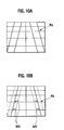
- irradiating a road R0 with a grid-shaped irradiation pattern when the vehicle V is making a stop and the road R0 has a small amount of relief forms a grid-shaped irradiation image on the road R0.
- Picking up the image of the grid-shaped irradiation pattern with the image pickup part 5 obtains the irradiation pattern Pa shown in Fig. 10A.
- the irradiator 3 and the image pickup part 5 each change in position relative to the road R0, as shown in Fig. 11. This brings about the irradiation image Pb shown in Fig.
- MV and WV each denote moving amount (deviation) of a per-pixel irradiation image.
- an operation speed of the image generating part 7 fails to catch up with an image pickup speed. Therefore, this removes an area where the irradiation pattern P of the current distance sensing image 5A is not irradiated, resulting in decreased image quality.
- the moving amount corrector 13 is configured to implement the following operations:
Landscapes
- Engineering & Computer Science (AREA)
- Physics & Mathematics (AREA)
- General Physics & Mathematics (AREA)
- Remote Sensing (AREA)
- Radar, Positioning & Navigation (AREA)
- Electromagnetism (AREA)
- Computer Networks & Wireless Communication (AREA)
- Multimedia (AREA)
- Computer Vision & Pattern Recognition (AREA)
- Measurement Of Optical Distance (AREA)
- Image Processing (AREA)
- Image Analysis (AREA)
- Closed-Circuit Television Systems (AREA)
- Studio Devices (AREA)
- Optical Radar Systems And Details Thereof (AREA)
Applications Claiming Priority (2)
| Application Number | Priority Date | Filing Date | Title |
|---|---|---|---|
| JP2006218572 | 2006-08-10 | ||
| JP2007189316A JP5061767B2 (ja) | 2006-08-10 | 2007-07-20 | 画像処理装置および画像処理方法 |
Publications (2)
| Publication Number | Publication Date |
|---|---|
| EP1887318A2 true EP1887318A2 (de) | 2008-02-13 |
| EP1887318A3 EP1887318A3 (de) | 2012-11-07 |
Family
ID=38671885
Family Applications (1)
| Application Number | Title | Priority Date | Filing Date |
|---|---|---|---|
| EP07015732A Ceased EP1887318A3 (de) | 2006-08-10 | 2007-08-09 | Bildprozessor und Bildverarbeitungsverfahren zur Objekterkennung und zur Detektion einer Entfernung zu diesem Objekt |
Country Status (3)
| Country | Link |
|---|---|
| US (1) | US8094888B2 (de) |
| EP (1) | EP1887318A3 (de) |
| JP (1) | JP5061767B2 (de) |
Cited By (5)
| Publication number | Priority date | Publication date | Assignee | Title |
|---|---|---|---|---|
| EP2557435A1 (de) * | 2011-08-09 | 2013-02-13 | Samsung Electro-Mechanics Co., Ltd | Bildverarbeitungsvorrichtung und -verfahren |
| CN103185567A (zh) * | 2011-12-27 | 2013-07-03 | 联想(北京)有限公司 | 一种电子设备及测量距离的方法 |
| CN103292779A (zh) * | 2012-02-28 | 2013-09-11 | 联想(北京)有限公司 | 一种测量距离的方法及图像获取设备 |
| CN104662472A (zh) * | 2012-09-25 | 2015-05-27 | 日产自动车株式会社 | 拍摄装置以及拍摄方法 |
| CN105814887A (zh) * | 2014-01-08 | 2016-07-27 | 三菱电机株式会社 | 图像生成装置 |
Families Citing this family (16)
| Publication number | Priority date | Publication date | Assignee | Title |
|---|---|---|---|---|
| JP5266709B2 (ja) * | 2007-10-19 | 2013-08-21 | 日産自動車株式会社 | 距離計測装置、距離計測方法および車両 |
| JP5167755B2 (ja) * | 2007-10-19 | 2013-03-21 | 日産自動車株式会社 | 光検出装置、光検出方法および車両 |
| US7920247B2 (en) * | 2007-11-30 | 2011-04-05 | Nissan Motor Co., Ltd. | Distance measurement system and distance measurement method |
| JP5266866B2 (ja) * | 2008-05-14 | 2013-08-21 | 日産自動車株式会社 | 障害物検出装置 |
| JPWO2010021090A1 (ja) * | 2008-08-20 | 2012-01-26 | パナソニック株式会社 | 距離推定装置、距離推定方法、プログラム、集積回路およびカメラ |
| JP5211938B2 (ja) * | 2008-08-28 | 2013-06-12 | 日産自動車株式会社 | 照射光抽出装置及び方法 |
| JP5251419B2 (ja) * | 2008-10-22 | 2013-07-31 | 日産自動車株式会社 | 距離計測装置および距離計測方法 |
| JP5939422B2 (ja) * | 2012-02-24 | 2016-06-22 | 日産自動車株式会社 | 距離計測装置 |
| US8768007B2 (en) | 2012-03-26 | 2014-07-01 | Tk Holdings Inc. | Method of filtering an image |
| US8824733B2 (en) | 2012-03-26 | 2014-09-02 | Tk Holdings Inc. | Range-cued object segmentation system and method |
| EP2728306A1 (de) * | 2012-11-05 | 2014-05-07 | Hexagon Technology Center GmbH | Verfahren und Vorrichtung zur Bestimmung dreidimensionaler Koordinaten eines Objekts |
| WO2014080937A1 (ja) * | 2012-11-21 | 2014-05-30 | 三菱電機株式会社 | 画像生成装置 |
| JP6127958B2 (ja) * | 2013-12-19 | 2017-05-17 | ソニー株式会社 | 情報処理装置、情報処理方法、並びにプログラム |
| TWI570674B (zh) * | 2015-12-17 | 2017-02-11 | 合盈光電科技股份有限公司 | 交通運輸工具之影像偵測系統 |
| WO2021166742A1 (ja) * | 2020-02-19 | 2021-08-26 | 日本電気株式会社 | 物体測距装置、方法、及びコンピュータ可読媒体 |
| DE102022203952A1 (de) | 2022-04-25 | 2023-10-26 | Psa Automobiles Sa | Verfahren und Vorrichtung zum Erfassen einer Umgebung eines Fahrzeugs |
Family Cites Families (10)
| Publication number | Priority date | Publication date | Assignee | Title |
|---|---|---|---|---|
| JPH02300608A (ja) * | 1989-05-16 | 1990-12-12 | O G Joho Syst Kk | 3次元形状計測装置 |
| JP3240835B2 (ja) * | 1994-06-09 | 2001-12-25 | 株式会社日立製作所 | 車両用距離計測装置 |
| JP2001174692A (ja) * | 1999-12-17 | 2001-06-29 | Olympus Optical Co Ltd | 測距装置 |
| US6810135B1 (en) * | 2000-06-29 | 2004-10-26 | Trw Inc. | Optimized human presence detection through elimination of background interference |
| JP2002036987A (ja) * | 2000-07-27 | 2002-02-06 | Nissan Motor Co Ltd | 車両周囲監視装置 |
| JP3846572B2 (ja) | 2001-09-20 | 2006-11-15 | ソニー株式会社 | 固体撮像装置 |
| GB2395261A (en) * | 2002-11-11 | 2004-05-19 | Qinetiq Ltd | Ranging apparatus |
| JP3922245B2 (ja) * | 2003-11-20 | 2007-05-30 | 日産自動車株式会社 | 車両周辺監視装置および方法 |
| US7164118B2 (en) * | 2004-10-29 | 2007-01-16 | Deere & Company | Method and system for obstacle detection |
| JP4561499B2 (ja) * | 2005-06-29 | 2010-10-13 | トヨタ自動車株式会社 | 車両用運転支援装置 |
-
2007
- 2007-07-20 JP JP2007189316A patent/JP5061767B2/ja active Active
- 2007-08-08 US US11/889,059 patent/US8094888B2/en active Active
- 2007-08-09 EP EP07015732A patent/EP1887318A3/de not_active Ceased
Non-Patent Citations (1)
| Title |
|---|
| None * |
Cited By (12)
| Publication number | Priority date | Publication date | Assignee | Title |
|---|---|---|---|---|
| EP2557435A1 (de) * | 2011-08-09 | 2013-02-13 | Samsung Electro-Mechanics Co., Ltd | Bildverarbeitungsvorrichtung und -verfahren |
| CN103185567A (zh) * | 2011-12-27 | 2013-07-03 | 联想(北京)有限公司 | 一种电子设备及测量距离的方法 |
| CN103185567B (zh) * | 2011-12-27 | 2015-04-29 | 联想(北京)有限公司 | 一种电子设备及测量距离的方法 |
| CN103292779A (zh) * | 2012-02-28 | 2013-09-11 | 联想(北京)有限公司 | 一种测量距离的方法及图像获取设备 |
| CN103292779B (zh) * | 2012-02-28 | 2015-06-24 | 联想(北京)有限公司 | 一种测量距离的方法及图像获取设备 |
| CN104662472A (zh) * | 2012-09-25 | 2015-05-27 | 日产自动车株式会社 | 拍摄装置以及拍摄方法 |
| EP2902841A4 (de) * | 2012-09-25 | 2015-08-05 | Nissan Motor | Bildaufnahmevorrichtung und bildaufnahmeverfahren |
| US9294686B2 (en) | 2012-09-25 | 2016-03-22 | Nissan Motor Co., Ltd. | Image capture apparatus and image capture method |
| CN104662472B (zh) * | 2012-09-25 | 2017-03-01 | 日产自动车株式会社 | 拍摄装置以及拍摄方法 |
| CN105814887A (zh) * | 2014-01-08 | 2016-07-27 | 三菱电机株式会社 | 图像生成装置 |
| CN105814887B (zh) * | 2014-01-08 | 2017-10-27 | 三菱电机株式会社 | 图像生成装置 |
| US9900485B2 (en) | 2014-01-08 | 2018-02-20 | Mitsubishi Electric Corporation | Image generation device |
Also Published As
| Publication number | Publication date |
|---|---|
| JP2008067362A (ja) | 2008-03-21 |
| JP5061767B2 (ja) | 2012-10-31 |
| US8094888B2 (en) | 2012-01-10 |
| EP1887318A3 (de) | 2012-11-07 |
| US20080044060A1 (en) | 2008-02-21 |
Similar Documents
| Publication | Publication Date | Title |
|---|---|---|
| EP1887318A2 (de) | Bildprozessor und Bildverarbeitungsverfahren zur Objekterkennung und zur Detektion einer Entfernung zu diesem Objekt | |
| EP1970839B1 (de) | Vorrichtung, Verfahren und Programm für die Gesichtsmerkmalerkennung | |
| EP3506169B1 (de) | Fahrerassistenzsystem und verfahren zur objekterkennung und -benachrichtigung | |
| KR102227843B1 (ko) | 차선 이탈 경보 시스템의 동작방법 | |
| US8199228B2 (en) | Method of and apparatus for correcting contour of grayscale image | |
| EP1887521A1 (de) | Fahrzeug- und strassenschilderkennungseinrichtung | |
| EP2477139A2 (de) | Spurwechsel-Warnsystem und -verfahren | |
| US8855417B2 (en) | Method and device for shape extraction, and size measuring device and distance measuring device | |
| US20160209927A1 (en) | Gesture manipulation device and method, program, and recording medium | |
| EP2723060A1 (de) | Fahrzeugmontierte kameravorrichtung | |
| EP3115930A1 (de) | Fehlfunktionsdiagnosevorrichtung | |
| JP2011165050A (ja) | 白線認識装置 | |
| CN112036210A (zh) | 一种检测障碍物的方法、装置、存储介质和移动机器人 | |
| EP2068569A1 (de) | Verfahren und Vorrichtung zum Erkennen und Anpassen von Farbwerten der Hautfarbenpixel | |
| US8055016B2 (en) | Apparatus and method for normalizing face image used for detecting drowsy driving | |
| EP1909230A1 (de) | Fahrzeug- und spurmarkierungserkennungsvorrichtung | |
| US20150169969A1 (en) | Object detection device for area around vehicle | |
| JP2014049918A (ja) | 車載撮像装置 | |
| JP2009294854A (ja) | 画像識別装置 | |
| US8050456B2 (en) | Vehicle and road sign recognition device | |
| JP4364275B2 (ja) | 画像処理方法、画像処理装置及びコンピュータプログラム | |
| JP2010211283A (ja) | 車線認識装置及び方法 | |
| EP3117758B1 (de) | Bildverarbeitungsvorrichtung und betriebsverfahren für bildverarbeitungsvorrichtung | |
| JP2007186916A (ja) | ウインドウ画像領域検出装置及びパワーウインドウ装置 | |
| JP4310317B2 (ja) | 可視成分割合算出方法、およびそれを用いた光学機器 |
Legal Events
| Date | Code | Title | Description |
|---|---|---|---|
| PUAI | Public reference made under article 153(3) epc to a published international application that has entered the european phase |
Free format text: ORIGINAL CODE: 0009012 |
|
| 17P | Request for examination filed |
Effective date: 20070809 |
|
| AK | Designated contracting states |
Kind code of ref document: A2 Designated state(s): AT BE BG CH CY CZ DE DK EE ES FI FR GB GR HU IE IS IT LI LT LU LV MC MT NL PL PT RO SE SI SK TR |
|
| AX | Request for extension of the european patent |
Extension state: AL BA HR MK YU |
|
| PUAL | Search report despatched |
Free format text: ORIGINAL CODE: 0009013 |
|
| AK | Designated contracting states |
Kind code of ref document: A3 Designated state(s): AT BE BG CH CY CZ DE DK EE ES FI FR GB GR HU IE IS IT LI LT LU LV MC MT NL PL PT RO SE SI SK TR |
|
| AX | Request for extension of the european patent |
Extension state: AL BA HR MK RS |
|
| RIC1 | Information provided on ipc code assigned before grant |
Ipc: G01B 11/25 20060101ALI20121002BHEP Ipc: G01C 3/08 20060101AFI20121002BHEP Ipc: G01C 11/14 20060101ALI20121002BHEP Ipc: G01C 11/00 20060101ALI20121002BHEP Ipc: G01S 17/08 20060101ALI20121002BHEP Ipc: G01S 17/02 20060101ALI20121002BHEP |
|
| 17Q | First examination report despatched |
Effective date: 20130410 |
|
| AKX | Designation fees paid |
Designated state(s): DE FR GB |
|
| STAA | Information on the status of an ep patent application or granted ep patent |
Free format text: STATUS: THE APPLICATION HAS BEEN REFUSED |
|
| 18R | Application refused |
Effective date: 20170623 |