EP1887242B1 - Einrichtung zur pneumatischen Betätigung einer Fahrzeugkupplung - Google Patents
Einrichtung zur pneumatischen Betätigung einer Fahrzeugkupplung Download PDFInfo
- Publication number
- EP1887242B1 EP1887242B1 EP20070013661 EP07013661A EP1887242B1 EP 1887242 B1 EP1887242 B1 EP 1887242B1 EP 20070013661 EP20070013661 EP 20070013661 EP 07013661 A EP07013661 A EP 07013661A EP 1887242 B1 EP1887242 B1 EP 1887242B1
- Authority
- EP
- European Patent Office
- Prior art keywords
- piston
- guide tube
- cylinder
- ring
- clutch
- Prior art date
- Legal status (The legal status is an assumption and is not a legal conclusion. Google has not performed a legal analysis and makes no representation as to the accuracy of the status listed.)
- Not-in-force
Links
Images


Classifications
-
- F—MECHANICAL ENGINEERING; LIGHTING; HEATING; WEAPONS; BLASTING
- F16—ENGINEERING ELEMENTS AND UNITS; GENERAL MEASURES FOR PRODUCING AND MAINTAINING EFFECTIVE FUNCTIONING OF MACHINES OR INSTALLATIONS; THERMAL INSULATION IN GENERAL
- F16D—COUPLINGS FOR TRANSMITTING ROTATION; CLUTCHES; BRAKES
- F16D25/00—Fluid-actuated clutches
- F16D25/08—Fluid-actuated clutches with fluid-actuated member not rotating with a clutching member
- F16D25/082—Fluid-actuated clutches with fluid-actuated member not rotating with a clutching member the line of action of the fluid-actuated members co-inciding with the axis of rotation
- F16D25/083—Actuators therefor
Definitions
- the present invention relates to a device for the pneumatic actuation of a vehicle clutch, with a cylinder and a cylinder displaceable relative to the cylinder axially guided on a guide tube, a clutch bearing for actuating the clutch acts and in the piston between the cylinder and a piston in the direction of the clutch actuation biasing spring device is arranged.
- Such a pneumatically actuated device may, for example, be a central release device for opening a clutch of a vehicle which is normally closed in the type which is thus pressed in the non-actuated position, for example by means of a disc spring.
- a pneumatically actuated Gottitzer can for example be found on a vehicle with a compressed air system use, so for example a truck.
- the FR 2 786 836 A1 shows a slave cylinder for the hydraulic actuation of a clutch with a cylinder and a cylinder displaceable relative to the piston, which acts on a Kupplungslagr for actuating the clutch and is disposed between the piston and cylinder a biasing spring means, wherein the cylinder housing and integral with a guide tube made of plastic is trained.
- the US Pat. No. 6,415,900 B1 is generally concerned with slave cylinders for clutch release systems and explicitly shows hydraulic slave cylinder with a piston and a cylinder housing, which are arranged on a metallic guide tube, wherein the cylinder housing is made of plastic and between the cylinder housing and the piston, a biasing spring is arranged.
- the cylinder of this known actuator is a sheet metal housing, which forms a piston raceway on its inside, wherein the piston is an annular piston and is axially guided with its inner diameter on the guide tube.
- the guide tube is inserted into an elongated nozzle of the sheet metal housing and fixed there by means of a welded joint.
- the guide tube is a drawn precision steel tube, which is connected by means of said weld with the sheet metal housing. Due to the strong heating during welding there is a risk of thermal distortion of the guide tube and moreover, the weld leads to corrosion problems on the guide tube. Also, the guide tube, since it is used for centering in the neck of the sheet-metal housing, have a longitudinal extension, which is significantly greater than the length required for the formation of the piston travel longitudinal extent, so that this leads to an increased cost of materials.
- the known actuator is manufactured as part of a series production, then a welding machine is to be integrated into a production line for automatic production, which regularly leads to significant setup overhead.
- the space between the piston and the cylinder is a pressure chamber, which must be sealed by the weld as a sealing seam, so that a proof of the tightness of the weld is to lead, which is why installed in the mass production line additionally a system for X-ray inspection must become. This also increases the set-up effort and thus the cost of manufacturing the known actuator considerably.
- the present invention is an object of the invention to provide a device for the pneumatic actuation of a vehicle clutch, which is inexpensive and more economical to produce, as the known actuator and the manufacturing cost significantly reduced.
- the dry running of the piston to the piston raceway and the radially inner seal of the Druchraums between the piston and cylinder should be ensured.
- the invention now provides a device for the pneumatic actuation of a vehicle clutch, which has a cylinder and a cylinder displaceable relative to the cylinder axially guided on a guide tube, a clutch bearing for actuating the clutch acts and between the piston and cylinder biasing the piston in the direction of the clutch actuation Spring device is arranged, wherein the guide tube and the cylinder are integrally formed of a plastic material and also the piston is formed of a plastic material.
- the guide tube thereby forms a tubular piece-shaped inner wall of the cylinder provided with a tubular outer housing and the inner wall and the outer housing together form a piston raceway for the piston.
- Between the cylinder and the piston is formed for the pressurization of the piston with, for example, compressed air from the compressed air system of the vehicle fillable pressure chamber, which occupies a large space and is made without separation points and due to its design of a plastic material a significant weight savings over the known actuator has the advantage and beyond due to the omission of a welded joint between the guide tube and the outer housing can be easily mounted.
- a weight advantage of about 40 percent can be achieved.
- both piston and cylinder are made of a plastic material.
- a sliding sleeve is arranged, at least in the contact region with the guide tube from a relative to the plastic material of the Guide tube is formed non-abrasive plastic material.
- the plastic material for the cylinder or the guide tube and the piston can be sch a fiber-reinforced, especially glass fiber reinforced plastic material based on a semi-crystalline, partially aromatic polyamide, in particular PA 6T / X, the EMS-Chemie (Germany) GmbH under the Designation Grivory® HTV-5H1 is available.
- the sliding sleeve now can in her Be formed contact area with the guide tube made of a plastic material without glass fiber component to avoid an abrasive effect on the guide tube.
- the piston of the device according to the invention is actuated for example via compressed air from the compressed air system of a vehicle and has for this purpose a piston crown provided with stiffening ribs and has between piston crown and outer housing of the cylinder a groove seal and a scraper, on the one hand provide a fluid-tight sealing space and on the other hand an elimination of any adhering to the piston race dirt particles, since the device according to the invention - when used for example on a commercial vehicle - is used in a harsh environment.
- the piston is an annular piston
- the radially inner recess is penetrated, for example, by a transmission input shaft of a transmission of the vehicle.
- the radially inner piston surface runs axially guided over the sliding sleeve on the guide tube and is axially biased by a spring device in the direction of the loading of the clutch.
- a retaining ring is now provided between the piston and the spring device, which biases a cylinder sealing against the guide tube Nutdichtring against the sliding sleeve, so that the pressure chamber between the piston and cylinder is sealed radially inward lying.
- the sliding sleeve acts on a arranged with the guide tube in contact scraper against the piston, so that the axial movement of the piston on the guide tube for stripping any Dirt particles on the radially inner piston raceway leads.
- the known actuator has arranged on the coupling side of the guide tube an end stop in the form of a securing ring, which is arranged in a formed on the guide tube circumferential groove.
- the piston sliding surface of the piston must pass the groove and is subject to a risk of damage there. If the piston of the known actuator, for example, be removed from the guide tube for maintenance purposes, the retaining ring must be removed for this purpose and the movement of the piston in the direction of the end of the guide tube is opposed by a circumferential sharp edge Umlaufnut, inevitably damaging the Kolbengleit Structure of the piston leads.
- an end stop for the piston displacement forming stop ring is arranged, but not, as is the case with the known actuator, by means of an outside arranged Umlaufnut is fixed, but for example by means of a cold-forming forming process on the guide tube can, for example, has a flanged edge, which surrounds the guide tube not from the outside, but from the inside, so that the guide tube is formed smooth outside and forms no peripheral edge, the one Movement of the piston over the end of the guide tube - for example, for maintenance - opposes.
- a surface for arranging the device on a gear forming the bottom of the cylinder radially star-shaped inwardly extending stiffening ribs, for a high-strength Cylinder provide that withstands the pressurization with compressed air.
- the invention also provides a device for pneumatic actuation of a vehicle clutch, wherein the guide tube and the cylinder are integrally formed of an aluminum material and also the piston is formed of an aluminum material.
- the guide tube can form a tubular inner wall of the provided with a tubular outer housing cylinder and the inner wall and the outer housing form a piston raceway, wherein the outer housing can be made as a machined forged aluminum forgings and the piston can be machined by means of an extrusion process machined. Also with this Embodiment, therefore, guide tube and cylinder are integrally formed without subsequently available separation points, as is the case with the known actuator, which is why the processing steps for retrofitting omitted and beyond there is also the risk of leaking separation points.
- the device for pneumatic actuation of a vehicle clutch has a cylinder formed by a cross-sectionally U-shaped annular member having a central recess is, in which the guide tube is determined by means of a cold-forming forming operation.
- the guide tube is determined by means of a cold-forming forming operation.
- the guide tube forms a tubular piece-shaped inner wall of the cylinder-shaped outer housing in the shape of the cross-sectionally U-shaped ring member cylinder and the inner wall and the outer housing form a piston career
- the ring member can be machined, for example by means of an extrusion process and the piston also by means an extrusion molding process, for example, can be made of an aluminum alloy.
- the cylinder is formed by an annular bottom and a cylindrical outer ring and the guide tube.
- the outer ring on the outer circumference of the bottom and the guide tube on the inner circumference of the bottom can also be defined by means of a cold-forming forming process and the outer ring and the guide tube thereby form a piston barrel.
- the piston When formed from a metallic material, such as an aluminum material or a stainless steel guide tube and a piston also formed of a metallic material such as an aluminum material, it is provided according to a development of the invention that the piston on its guide tube facing the inner wall by means of guide belts preferably PTFE (polytetrafluoroethylene) rests against the guide tube and can be displaced relative to the guide tube, so that no abrasion effect arises between the guide tube and the piston inner race of the annular piston.
- PTFE polytetrafluoroethylene
- the annular piston can have according to a development of the invention on its piston inner wall facing the inner wall and outer wall at least one Nutdichtring and a scraper, on the one hand ensures a seal of the pressure chamber and on the other hand for eliminating any adhering to the piston race dirt particles.
- the guide tube has a shoulder, by means of which it can be brought to the ring component for conditioning.
- the guide tube can have an end stop for the piston formed by means of a cold-forming forming process.
- the device according to the invention is provided, for example, for use on a commercial vehicle with a correspondingly rough working environment.
- a dirt protection ring cup-shaped cup-shaped overlaps and the dirt protection ring between the piston and acted upon by the piston bearing ring of the clutch bearing is fixed and between a cylinder outer wall and an inner wall the dirt protection ring is arranged a dirt wiper, for example in the form of a felt ring.
- FIG. 1 The drawing shows a sectional view of a first embodiment of a clutch actuating device according to the invention, which is provided for in particular pneumatic actuation.
- the illustrated clutch actuator 1 has an integrally formed housing 2, which simultaneously forms the cylinder 3 and the guide tube 4. Within the housing 2, a pressure chamber 5 for the application of an axially guided on the guide tube 4 piston 6 is formed.
- the cylinder 3 and the guide tube 4 are made of PA 6T / 6I-GF50, a glass fiber reinforced plastic material, which is available under the name Grivory® HTV-5H1 from EMS-Chemie (Germany) AG and has a glass fiber content of 50 weight percent. It is a thermally stable in the present application range of - 40 ° C to + 120 ° C plastic, which can also be used for the production of the piston 6.
- spacer sleeves 8 are provided for receiving screws or the like, by means of which the device can be attached to a flange surface of a gear housing or the like. Also, an opening 9 for the filling of the pressure chamber 5 of the cylinder 3 is formed on the bottom 7. In the opening 9, for example by means of an ultrasonic welding process, a threaded insert for a compressed air connection can be established.
- stiffening ribs 10 On the outer circumference of the cylinder 3 spaced radially extending stiffening ribs 10 are provided. Also on the bottom 7 stiffening ribs 10 are provided, which extend in a star-shaped direction inwardly to a passage 11 which is penetrated by a transmission input shaft 12 of a transmission, not shown.
- the stiffening ribs 10 ensure that the housing 2 can withstand usual operating pressures of, for example, up to 10 bar of compressed air systems of commercial vehicles within the temperature range described above.
- the piston 6 has a piston head 13 with stiffening ribs 14 and can be acted upon by the pressure prevailing in the pressure chamber 5 in the direction of acting on a plate spring 15 shown in dashed lines a clutch, not shown.
- the upper level in the drawing plane of the Fig. 1 corresponds to the position of the piston 5 relative to the cylinder in a closed clutch, while in the drawing in Fig. 1 lower half of the drawing shows the applied position of the piston 5, in which this acts on a clutch bearing 16, the plate spring 15 to open the clutch.
- the piston 6, which is an annular piston, has on its outer circumference a scraper 17 for stripping off any dirt particles from the piston running path formed on the cylinder 3, and a groove sealing ring 18 which serves to seal the pressure chamber 5.
- the piston 6 is biased by a spring device 19 in the direction of the loading of the plate spring 15, wherein the spring device acts on a retaining ring 20 which presses a Nutdichtring 18 against a sliding sleeve 21 which is formed at least in the contact region with the guide tube 4 of a non-abrasive plastic material and ensures a sliding movement of the piston 6 on the guide tube 4.
- the piston 6 also has on its side facing the guide tube 4 inside a scraper 17 which is provided for stripping any on the guide tube 4 externally adhering dirt particles.
- the pressure chamber 5, the piston 6 and the cylinder 3 with its tubular outer housing 22 are cup-shaped overlapped by a dirt protection ring 23.
- the dirt protection ring 23 is thereby clamped with a collar 24 between the piston 6 and the coupling bearing 16 and engages over the outer housing 22nd
- a wiper in the form of, for example, a felt ring 25 is provided so that the cup-shaped dirt protection ring 23 is guided with its inner wall of the felt ring 25 along when the piston 6 from the in the upper half of the drawing of Fig. 1 shown position with minimal extension in the lower half of the drawing Fig. 1 shown position with maximum extension and while dirt particles are trapped by the felt ring 25.
- the dirt protection ring 23 has arranged on its outer housing a permanent magnet 26 which is provided for the travel measurement of the travel of the piston 6 along its travel path and that together with a fixed to the bottom 7 displacement sensor 27th
- an end stop 28 is fixed by means of a bead on the coupling-side end portion of the guide tube 4, so that no sharp edge is formed in an assembly of the piston 6 or disassembly of the Piston 6 on the guide tube 4 could damage the piston.
- the guide tube 4 also has stiffening ribs, which in Fig. 1 can be seen as a visible edge on the guide tube 4.
- Fig. 2 The drawing shows a modified non-inventive embodiment of the clutch actuator. 1
- Fig. 2 illustrated embodiment differs from the in Fig. 1 illustrated embodiment essentially in that the cylinder 3 is formed with the tubular outer housing 22 and the guide tube 4 made of an aluminum material, but in turn has a one-piece configuration and machined, for example by means of a forging process machined.
- the piston 6 is machined by means of an extrusion process and can also be made of an aluminum material.
- Piston 6 has both on its outer surface and on its inner surface in each case a scraper 17 and a groove seal 18.
- the piston 6 has on its radially inner circumferential surface guide bands 29, which are formed for example of polytetrafluoroethylene (PTFE) and prevent wear of the contact surface between the piston 6 and the guide tube 4.
- the piston 6 is biased by a spring means 19 in the direction of the plate spring 15 and the cylinder 3 can be fixed by means of a screw connection to a flange of a transmission, not shown.
- the transmission input shaft 12 passes through the clutch actuator 1 via a passage 11, in whose area a shaft seal 30 - similar to the embodiment in Fig. 1 - is provided.
- a dirt protection ring 23 engages over the piston 6 and the piston running path formed on the inner circumferential surface of the outer housing 22 in order to prevent dirt from entering.
- On the outer periphery of the tubular outer housing is - similar to the embodiment in Fig. 1 -
- a felt ring 25 is arranged, which touches the inner wall of the dirt protection ring 23 in its axial movement during the displacement of the piston 4 along.
- a permanent magnet 26 is arranged, which serves together with the displacement sensor 27, the displacement measurement of the piston 6 along its travel.
- Fig. 3 shows a modified non-inventive embodiment of the actuator 1, which differs from the in Fig. 2 illustrated embodiment essentially differs in that the cylinder 3 is formed by a cross-sectionally U-shaped ring member and the guide tube 4, so that guide tube and cylinder are not integrally formed, but the guide tube 4 fixed by means of a cold-forming forming operation on the ring member 31 becomes.
- the annular member 31 in the region of its central recess have a collar 32 which serves as a receptacle for a bead 33 of the guide tube 4.
- the guide tube 4 on the ring member 31 to form the cylinder 3 can be set so that no thermal distortion of the guide tube formed, for example, of a stainless steel in the form of a drawn precision tube 4 is formed.
- To the pressure chamber 5 To seal, has the U-shaped annular member 31 in the region of its recess 34 for receiving the guide tube 4, a circumferential annular groove in which, for example, an O-ring 35 can be used prior to assembly of the guide tube 4.
- the guide tube 4 has a shoulder 36 which comes to center the guide tube 4 on the ring member to the plant.
- the further embodiment and function of the clutch actuator 1 according to Fig. 3 corresponds to that after Fig. 2 so that to avoid repetition on the description of the Fig. 2 is referenced.
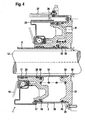
- FIG. 4 a sectional view of another modified non-inventive embodiment of the clutch actuator. 1
- Fig. 4 illustrated embodiment differs from the in Fig. 3 illustrated embodiment essentially in that the ring member 31 is omitted and replaced by an annular bottom 37, on the outer circumference by means of a cold-forming deformation in the form of a flange, an outer ring 38 is arranged.
- the guide tube 4 is according to the in Fig. 4 illustrated embodiment on the inner circumference of the bottom 37 also fixed by means of a bead 39.
- an O-ring 35 and also on the outer periphery of the bottom 37 an O-ring 40 between the outer ring 38 and the bottom 37 is fixed to the pressure chamber 5, in which the piston 6 moves to seal.
Description
- Die vorliegende Erfindung betrifft eine Einrichtung zur pneumatischen Betätigung einer Fahrzeugkupplung, mit einem Zylinder und einem relativ zum Zylinder verlagerbarem Kolben, der an einem Führungsrohr axial geführt ein Kupplungslager zur Betätigung der Kupplung beaufschlägt und bei der zwischen Kolben und Zylinder eine den Kolben in Richtung zur Kupplungsbetätigung vorspannende Federeinrichtung angeordnet ist.
- Bei einer solchen pneumatisch betätigten Einrichtung kann es sich beispielsweise um einen Zentralausrücker zum Öffnen einer Kupplung eines Fahrzeugs handeln, die vom Typ normal geschlossen ist, die also in der nicht betätigten Stellung beispielsweise mittels einer Tellerfeder zugedrückt ist. Ein solcher pneumatisch betätigter Zentralausrücker kann beispielsweise an einem Fahrzeug mit einer Druckluftanlage Einsatz finden, also beispielsweise einem Lastkraftwagen.
- Die
FR 2 786 836 A1 - Die
US 6,415,900 B1 beschäftigt sich allgemein mit Nehmerzylindern für Kupplungsausrückersysteme und zeigt explizit hydraulische Nehmerzylinder mit einem Kolben und einem Zylindergehäuse, der auf einem metallischen Führungsrohr angeordnet sind, wobei das Zylindergehäuse aus Kunststoff gefertigt ist und zwischen dem Zylindergehäuse und dem Kolben eine Vorspannfeder angeordnet ist. - Anhand der
DE 103 14 961 A1 ist eine Betätigungseinrichtung für eine Fahrzeugkupplung bekannt geworden, die einen Zylinder besitzt und einen relativ zum Zylinder verlagerbaren Kolben, der an einem Führungsrohr axial geführt ist und ein Kupplungslager zur Betätigung der Kupplung beaufschlägt. Zudem besitzt diese bekannte Betätigungseinrichtung eine Druckfeder, die den Kolben in Richtung zur Kupplungsbetätigung hin mit Vorlast beaufschlägt. - Bei dem Zylinder dieser bekannten Betätigungseinrichtung handelt es sich um ein Blechgehäuse, das an seiner Innenseite eine Kolbenlaufbahn ausbildet, wobei der Kolben ein Ringkolben ist und mit seinem Innendurchmesser an dem Führungsrohr axial geführt ist. Um nun eine Zentrierung zwischen dem Führungsrohr und dem Blechgehäuse zu erreichen, wird das Führungsrohr in einen langgestreckten Stutzen des Blechgehäuses eingesetzt und dort mittels einer Schweißverbindung festgelegt.
- Bei dem Führungsrohr handelt es sich um ein gezogenes Präzisionsstahlrohr, welches mittels der genannten Schweißverbindung mit dem Blechgehäuse verbunden wird. Durch die starke Erhitzung beim Schweißen besteht die Gefahr eines thermischen Verzugs des Führungsrohrs und darüber hinaus führt die Schweißverbindung zu Korrosionsproblemen am Führungsrohr. Auch muss das Führungsrohr, da es zur Zentrierung in den Stutzen des Blechgehäuses eingesetzt wird, eine Längserstreckung besitzen, die deutlich größer ist, als die für die Bildung der Kolbenlaufbahn erforderliche Längserstreckung, so dass dies zu einem erhöhten Materialaufwand führt.
- Wird die bekannte Betätigungseinrichtung im Rahmen einer Serienfertigung gefertigt, so ist in eine Fertigungsstraße zur automatischen Fertigung ein Schweißautomat zu integrieren, was regelmäßig zu deutlichem Rüstmehraufwand führt. Zudem handelt es sich bei dem Raum zwischen dem Kolben und dem Zylinder um einen Druckraum, der von der Schweißnaht als Dichtnaht abgedichtet werden muss, so dass ein Nachweis über die Dichtheit der Schweißnaht zu führen ist, weshalb in der Serienfertigungsanlage zusätzlich eine Anlage zur Röntgenprüfung installiert werden muss. Auch dies erhöht den Rüstaufwand und damit die Kosten der Fertigung der bekannten Betätigungseinrichtung erheblich.
- Ausgehend hiervon liegt der vorliegenden Erfindung nunmehr die Aufgabe zugrunde, eine Einrichtung zur pneumatischen Betätigung einer Fahrzeugkupplung zu schaffen, die kostengünstig und wirtschaftlicher herzustellen ist, als die bekannte Betätigungseinrichtung und den Fertigungsaufwand deutlich verringert. Dabei soll auch der Trockenlauf des Kolbens an der Kolbenlaufbahn sowie die radial innenliegende Abdichtung des Druchraums zwischen Kolben und Zylinder gewährleistet sein.
- Die Erfindung weist nunmehr zur Lösung dieser Aufgabe eine Einrichtung mit den Merkmalen des Anspruchs 1 auf. Vorteilhafte Ausgestaltungen hiervon sind in den weiteren Ansprüchen beschrieben.
- Die Erfindung schafft nunmehr eine Einrichtung zur pneumatischen Betätigung einer Fahrzeugkupplung, die einen Zylinder und einen relativ zum Zylinder verlagerbaren Kolben aufweist, der an einem Führungsrohr axial geführt ein Kupplungslager zur Betätigung der Kupplung beaufschlägt und zwischen Kolben und Zylinder eine den Kolben in Richtung zur Kupplungsbetätigung vorspannende Federeinrichtung angeordnet ist, wobei das Führungsrohr und der Zylinder einstückig aus einem Kunststoffwerkstoff ausgebildet sind und auch der Kolben aus einem Kunststoffwerkstoff ausgebildet ist.
- Das Führungsrohr bildet dabei eine rohrstückförmige Innenwand des mit einem rohrstückförmigen Außengehäuse versehenen Zylinders und die Innenwand und das Außengehäuse bilden zusammen eine Kolbenlaufbahn für den Kolben. Zwischen dem Zylinder und dem Kolben bildet sich ein für die Druckbeaufschlagung des Kolbens mit beispielsweise Druckluft aus der Druckluftanlage des Fahrzeugs befüllbarer Druckraum aus, der einen großen Bauraum einnimmt und ohne Trennstellen hergestellt ist und aufgrund seiner Ausgestaltung aus einem Kunststoffwerkstoff eine deutliche Gewichtsersparnis gegenüber der bekannten Betätigungseinrichtung zum Vorteil hat und darüber hinaus aufgrund des Wegfalls einer Schweißverbindung zwischen dem Führungsrohr und dem Außengehäuse einfach montiert werden kann. So kann mit der erfindungsgemäßen Einrichtung gegenüber der bekannten Kupplungsbetätigungseinrichtung ein Gewichtsvorteil von etwa 40 Prozent erreicht werden.
- Es ist bei dieser erfindungsgemäßen Einrichtung zur pneumatischen Betätigung der Fahrzeugkupplung vorgesehen, dass sowohl Kolben als auch Zylinder aus einem Kunststoffwerkstoff gefertigt sind. Um nun die Möglichkeit eines Trockenlaufs beziehungsweise eines Laufs des Kolbens an der Kolbenlaufbahn mittels einer Dauerschmierung zu gewähren, ist es gemäß der Erfindung vorgesehen, dass zwischen Kolben und Führungsrohr eine Gleithülse angeordnet ist, die zumindest im Kontaktbereich mit dem Führungsrohr aus einem relativ zum Kunststoffwerkstoff des Führungsrohrs nicht abrasiven Kunststoffwerkstoff ausgebildet ist.
- Bei dem Kunststoffwerkstoff für den Zylinder beziehungsweise das Führungsrohr und den Kolben kann es sch um einen faserverstärkten, insbesondere glasfaserverstärkten Kunststoffwerkstoff handeln auf der Basis eines teilkristallinen, partiell aromatischen Polyamids, insbesondere PA 6T/X, der von EMS-Chemie (Deutschland) GmbH unter der Bezeichnung Grivory® HTV-5H1 verfügbar ist. Die Gleithülse nun kann in ihrem Kontaktbereich mit dem Führungsrohr aus einem Kunststoffwerkstoff ohne Glasfaserkomponente zur Vermeidung einer abrasiven Wirkung am Führungsrohr ausgebildet sein.
- Der Kolben der erfindungsgemäßen Einrichtung wird beispielsweise über Druckluft aus der Druckluftanlage eines Fahrzeugs betätigt und weist zu diesem Zweck einen mit Versteifungsrippen versehenen Kolbenboden auf und besitzt zwischen Kolbenboden und Außengehäuse des Zylinders einen Nutdichtring und einen Abstreifer, die einerseits für einen fluiddichten Dichtraum sorgen und andererseits für eine Beseitigung von etwaigen an der Kolbenlaufbahn anhaftender Schmutzpartikel, da die erfindungsgemäße Einrichtung - wenn sie beispielsweise an einem Nutzfahrzeug verwendet wird - in einer rauen Umgebung eingesetzt wird.
- Bei dem Kolben handelt es sich um einen Ringkolben, dessen radial innen liegende Ausnehmung beispielsweise von einer Getriebeeingangswelle eines Getriebes des Fahrzeugs durchsetzt wird.
- Die radial innen liegende Kolbenfläche läuft über die Gleithülse an dem Führungsrohr axial geführt und wird von einer Federeinrichtung in Richtung der Beaufschlagung der Kupplung axial vorgespannt. Gemäß der Erfindung ist zwischen dem Kolben und der Federeinrichtung nunmehr ein Haltering vorgesehen, der einen den Zylinder gegen das Führungsrohr abdichtenden Nutdichtring gegen die Gleithülse vorspannt, so dass der Druckraum zwischen Kolben und Zylinder auch radial innen liegend abgedichtet ist.
- Zur Beseitigung etwaiger auch an der radial innen liegenden Kolbenlaufbahn anhaftender Schmutzpartikel ist es nach einer Weiterbildung der Erfindung vorgesehen, dass die Gleithülse einen mit dem Führungsrohr in Kontakt angeordneten Abstreifer gegen den Kolben beaufschlägt, so dass die Axialbewegung des Kolbens an dem Führungsrohr zu einem Abstreifen etwaiger Schmutzpartikel an der radial innen liegenden Kolbenlaufbahn führt.
- Die bekannte Betätigungseinrichtung besitzt kupplungsseitig an dem Führungsrohr einen Endanschlag in der Form eines Sicherungsrings angeordnet, der in einer an dem Führungsrohr ausgebildeten umlaufenden Nut angeordnet ist.
- Wird nun der Kolben der bekannten Betätigungseinrichtung auf das Führungsrohr aufgesetzt, so muss die Kolbengleitfläche des Kolbens die Nut passieren und unterliegt dort einer Gefahr einer Beschädigung. Muss der Kolben der bekannten Betätigungseinrichtung beispielsweise zu Wartungszwecken von dem Führungsrohr abgenommen werden, so muss zu diesem Zweck der Sicherungsring entfernt werden und der Bewegung des Kolbens in Richtung des Endes des Führungsrohrs steht eine umlaufende scharfe Kante der Umlaufnut entgegen, die unweigerlich zur Beschädigung der Kolbengleitfläche des Kolbens führt.
- Um nun diese Problematik zu beseitigen, ist es nach einer Weiterbildung der Erfindung vorgesehen, dass am kupplungsseitigen Endbereich des Führungsrohrs ein einen Endanschlag für die Kolbenverlagerung bildender Anschlagring angeordnet ist, der aber nicht, wie dies bei der bekannten Betätigungseinrichtung der Fall ist, mittels einer außen angeordneten Umlaufnut festgelegt wird, sondern beispielsweise mittels eines kalt verformenden Umformvorgangs am Führungsrohr festgelegt werden kann, beispielsweise einen Bördelrand besitzt, der das Führungsrohr nicht von außen, sondern von innen umgreift, so dass das Führungsrohr außen glatt ausgebildet ist und keine Umlaufkante bildet, die einer Bewegung des Kolbens über das Ende des Führungsrohrs - beispielsweise zu Wartungsarbeiten - entgegensteht.
- Nach einer Weiterbildung der Erfindung ist es vorgesehen, dass am Außengehäuse radial außen im Abstand zueinander angeordnete umlaufende Versteifungsrippen vorgesehen sind und an einem, eine Fläche zur Anordnung der Einrichtung an einem Getriebe bildenden Boden des Zylinders radial sternförmig nach innen verlaufende Versteifungsrippen, die für einen hochfesten Zylinder sorgen, der der Druckbeaufschlagung mit Druckluft standhält.
- Neben dieser vorstehend beschriebenen Ausführungsform schafft die Erfindung auch eine Einrichtung zur pneumatischen Betätigung einer Fahrzeugkupplung, bei der das Führungsrohr und der Zylinder einstückig aus einem Aluminiumwerkstoff ausgebildet sind und auch der Kolben aus einem Aluminiumwerkstoff ausgebildet ist.
- Das Führungsrohr kann dabei eine rohrstückförmige Innenwand des mit einem rohrstückförmigen Außengehäuse versehenen Zylinders bilden und die Innenwand und das Außengehäuse bilden eine Kolbenlaufbahn, wobei das Außengehäuse als spanend nachgearbeitetes Schmiedeteil aus Aluminium gefertigt sein kann und der Kolben mittels eines Fließpressvorgangs spanend nachbearbeitet gefertigt sein kann. Auch bei dieser Ausführungsform sind daher Führungsrohr und Zylinder einstückig ausgebildet ohne nachträglich zu verfügende Trennstellen, wie dies bei der bekannten Betätigungseinrichtung der Fall ist, weshalb die Bearbeitungsschritte zum nachträglichen Verfügen wegfallen und darüber hinaus auch nicht die Gefahr undichter Trennstellen besteht.
- Es hat sich gezeigt, dass bei der bekannten Betätigungseinrichtung bei einer mehrteiligen Ausbildung des Druckraums aus Außengehäuse und Führungsrohr die Schweißnaht zwischen dem Führungsrohr und dem Außengehäuse aus den vorstehend genannten Gründen problematisch ist.
- Um nun auch die Möglichkeit einer Bildung des Druckraums in nicht einstückiger Weise zu schaffen, ist es nach einer Weiterbildung der Erfindung vorgesehen, dass die Einrichtung zur pneumatischen Betätigung einer Fahrzeugkupplung einen Zylinder besitzt, der von einem querschnittlich U-förmigen Ringbauteil mit einer mittigen Ausnehmung gebildet ist, in der das Führungsrohr mittels eines kalt verformenden Umformvorgangs festgelegt ist. Auf diese Weise ist es beispielsweise möglich, mittels einer Umbördelung des motorseitigen Endbereichs des Führungsrohrs einen vom U-förmigen Ringbauteil und dem Führungsrohr gebildeten Aufnahmeraum für den Kolben zu schaffen.
- Das Führungsrohr bildet dabei eine rohrstückförmige Innenwand des mit einem rohrstückförmigen Außengehäuse in der Form des querschnittlich U-förmigen Ringbauteils versehenen Zylinders und die Innenwand und das Außengehäusen bilden eine Kolbenlaufbahn, wobei das Ringbauteil beispielsweise mittels eines Fließpressvorgangs spanend nachbearbeitet gefertigt sein kann und der Kolben ebenfalls mittels eines Fließpressvorgangs spanend beispielsweise aus einer Aluminiumlegierung gefertigt sein kann.
- Schließlich ist es nach einer Weiterbildung der Erfindung zur Schaffung eines aus mehreren Bestandteilen zusammengesetzten Druckraums des Zylinders vorgesehen, dass der Zylinder von einem kreisringförmigen Boden und einem zylinderförmigen Außenring sowie dem Führungsrohr gebildet ist.
- Dabei kann der Außenring am Außenumfang des Bodens und das Führungsrohr am Innenumfang des Bodens ebenfalls mittels eines kalt verformenden Umformvorgangs festgelegt sein und der Außenring sowie das Führungsrohr dabei eine Kolbenlaufbahn bilden. Hier ist es beispielsweise möglich, den Boden mittels eines Schmiedevorgangs aus einem Aluminiumwerkstoff herzustellen, an dem sowohl der Außenring als auch das Führungsrohr mittels eines Bördelvorgangs festgelegt werden können, so dass keine zu einem Temperaturverzug der Kolbenlaufbahn führenden Schweißvorgänge notwendig sind.
- Bei aus einem metallischen Werkstoff, wie beispielsweise einem Aluminiumwerkstoff oder aus einem Edelstahl gebildetem Führungsrohr und einem ebenfalls aus einem metallischen Werkstoff, wie beispielsweise einem Aluminiumwerkstoff gebildeten Kolben ist es nach einer Weiterbildung der Erfindung vorgesehen, dass der Kolben an seiner dem Führungsrohr zugewandten Innenwand mittels Führungsbändern aus vorzugsweise PTFE (Polytetrafluorethylen) am Führungsrohr anliegt und relativ zum Führungsrohr verlagert werden kann, so dass zwischen dem Führungsrohr und der Kolbeninnenlaufbahn des Ringkolbens keine Abrasionswirkung entsteht.
- Der Ringkolben kann nach einer Weiterbildung der Erfindung an seiner der Kolbenlaufbahn zugewandten Innenwand und Außenwand jeweils mindestens einen Nutdichtring sowie einen Abstreifer besitzen, der einerseits für eine Abdichtung des Druckraums sorgt und andererseits für eine Beseitigung etwaiger an der Kolbenlaufbahn anhaftender Schmutzpartikel.
- Bei der mittels eines U-förmigen Ringbauteils und dem Führungsrohr in der mittigen Ausnehmung des Ringbauteils gebildeten Konfiguration ist es nach einer Weiterbildung der Erfindung vorgesehen, dass das Führungsrohr einen Absatz aufweist, mittels dem es am Ringbauteil zur Anlage gebracht werden kann. Um nun das Problem scharfkantiger Endbereiche des Führungsrohrs zu vermeiden, kann das Führungsrohr einen mittels eines kalt verformenden Umformvorgangs gebildeten Endanschlag für den Kolben besitzen.
- Wie es vorstehend bereits erwähnt wurde, ist die erfindungsgemäße Einrichtung beispielsweise zur Verwendung an einem Nutzfahrzeug vorgesehen mit entsprechend rauer Arbeitsumgebung. Um nun diesen rauen Einsatzbedingungen widerstehen zu können, ist es nach einer Weiterbildung aller vorstehend beschriebenen Ausführungsformen vorgesehen, dass ein Schmutzschutzring die Kolbenlaufbahn topfförmig übergreift und der Schmutzschutzring zwischen Kolben und einem vom Kolben beaufschlagten Lagerring des Kupplungslagers festgelegt ist und sich zwischen einer Zylinderaußenwand und einer Innenwand des Schmutzschutzrings ein Schmutzabstreifer beispielsweise in der Form eines Filzrings angeordnet befindet.
- Erfährt nun der Kolben entlang der Kolbenlaufbahn eine Verlagerungsbewegung, so führt dies ebenfalls zu einer Verlagerungsbewegung des Schmutzschutzrings, so dass der an der Zylinderaußenwand festgelegte Filzring entlang der Innenwand des Schmutzschutzrings entlang streift und gegen den Schmutzschutzring abdichtet, so dass Schmutzpartikel am Eindringen in den Raum innerhalb des Schmutzschutzrings gehindert werden.
- Die Erfindung wird im Folgenden anhand der Zeichnung näher erläutert. Diese zeigt in:
-
Fig 1 eine Schnittdarstellung einer ersten Ausführungsform einer Einrichtung zur pneumatischen Betätigung einer Kupplung nach der vorliegenden Erfindung; -
Fig. 2 eine Schnittdarstellung einer zweiten nicht erfingungsgemäßen Ausführungsform; -
Fig. 3 eine Schnittdarstellung einer dritten nicht erfingungsgemäßen Ausführungsform; und -
Fig. 4 eine Schnittdarstellung einer vierten nicht erfingungsgemäßen Ausführungsform. -
Fig. 1 der Zeichnung zeigt eine Schnittdarstellung einer ersten Ausführungsform einer erfindungsgemäßen Kupplungsbetätigungseinrichtung, die zur insbesondere pneumatischen Betätigung vorgesehen ist. - Die dargestellte Kupplungsbetätigungseinrichtung 1 weist ein einstückig ausgebildetes Gehäuse 2 auf, das gleichzeitig den Zylinder 3 und das Führungsrohr 4 bildet. Innerhalb des Gehäuses 2 ist ein Druckraum 5 für die Beaufschlagung eines am Führungsrohr 4 axial geführten Kolbens 6 ausgebildet.
- Der Zylinder 3 und das Führungsrohr 4 sind aus PA 6T/6I-GF50 gebildet, einem glasfaserverstärktem Kunststoffwerkstoff, der unter der Bezeichnung Grivory® HTV-5H1 von der EMS-Chemie (Deutschland) AG erhältlich ist und einen Glasfaseranteil von 50 Gewichtsprozent besitzt. Es handelt sich dabei um einen im vorliegenden Anwendungsbereich von - 40° C bis + 120° C thermisch stabilen Kunststoff, der auch zur Fertigung des Kolbens 6 verwendet werden kann.
- An dem Boden 7 des Zylinders 3 sind Abstandshülsen 8 zur Aufnahme von Schrauben oder dergleichen vorgesehen, mittels der die Einrichtung an einer Flanschfläche eines Getriebegehäuses oder dergleichen befestigt werden kann. Auch ist am Boden 7 eine Öffnung 9 für die Befüllung des Druckraums 5 des Zylinders 3 ausgebildet. In der Öffnung 9 kann beispielsweise mittels eines Ultraschallschweißvorgangs ein Gewindeeinsatz für einen Druckluftanschluss festgelegt werden.
- Am Außenumfang des Zylinders 3 sind im Abstand zueinander angeordnete radial verlaufende Versteifungsrippen 10 vorgesehen. Auch am Boden 7 sind Versteifungsrippen 10 vorgesehen, die sternförmig in Richtung nach innen gerichtet zu einem Durchlass 11 verlaufen, der von einer Getriebeeingangswelle 12 eines nicht näher dargestellten Getriebes durchsetzt wird. Die Versteifungsrippen 10 sorgen dafür, dass das Gehäuse 2 innerhalb des vorstehend beschriebenen Temperaturbereichs üblichen Betriebsdrücken von beispielsweise bis zu 10 bar von Druckluftanlagen von Nutzfahrzeugen standhält.
- Der Kolben 6 weist einen Kolbenboden 13 mit Versteifungsrippen 14 auf und kann von dem im Druckraum 5 herrschenden Druck in Richtung zur Beaufschlagung einer gestrichelt dargestellten Tellerfeder 15 einer nicht dargestellten Kupplung beaufschlagt werden. Die in der Zeichnungsebene obere Darstellung der
Fig. 1 entspricht dabei der Stellung des Kolbens 5 relativ zum Zylinder bei einer geschlossenen Kupplung, während die in der Zeichnung inFig. 1 untere Zeichnungshälfte die beaufschlagte Stellung des Kolbens 5 zeigt, bei der dieser also über ein Kupplungslager 16 die Tellerfeder 15 zum Öffnen der Kupplung beaufschlagt. - Der Kolben 6, bei dem es sich um einen Ringkolben handelt, besitzt an seinem Außenumfang einen Abstreifer 17 zum Abstreifen etwaiger Schmutzpartikel von der am Zylinder 3 gebildeten Kolbenlaufbahn sowie einen Nutdichtring 18, der dem Abdichten des Druckraums 5 dient. Der Kolben 6 wird von einer Federeinrichtung 19 in Richtung der Beaufschlagung der Tellerfeder 15 vorgespannt, wobei die Federeinrichtung einen Haltering 20 beaufschlägt, der einen Nutdichtring 18 gegen eine Gleithülse 21 drückt, die zumindest im Kontaktbereich mit dem Führungsrohr 4 aus einem nicht abrasiven Kunststoffwerkstoff gebildet ist und für eine Gleitbewegung des Kolbens 6 am Führungsrohr 4 sorgt.
- Der Kolben 6 weist darüber hinaus an seiner dem Führungsrohr 4 zugewandten Innenseite einen Abstreifer 17 auf, der zum Abstreifen etwaiger am Führungsrohr 4 außen anhaftender Schmutzpartikel vorgesehen ist.
- Der Druckraum 5, der Kolben 6 und der Zylinder 3 mit seinem rohrstückförmigen Außengehäuse 22 werden von einem Schmutzschutzring 23 topfförmig übergriffen. Der Schmutzschutzring 23 befindet sich dabei mit einem Bund 24 zwischen dem Kolben 6 und dem Kupplungslager 16 eingeklemmt und übergreift das Außengehäuse 22.
- Am Außengehäuse 22 ist ein Schmutzabstreifer in der Form beispielsweise eines Filzrings 25 vorgesehen, so dass der topfförmige Schmutzschutzring 23 mit seiner Innenwand an dem Filzring 25 entlang geführt wird, wenn sich der Kolben 6 aus der in der oberen Hälfte der Zeichnung der
Fig. 1 dargestellten Stellung mit minimaler Extension in die in der unteren Zeichnungshälfte derFig. 1 dargestellten Stellung mit maximaler Extension begibt und dabei werden Schmutzpartikel vom Filzring 25 eingefangen. - Der Schmutzschutzring 23 besitzt an seinem Außengehäuse einen Permanentmagneten 26 angeordnet, der zur Wegmessung des Verfahrwegs des Kolbens 6 entlang seines Verfahrwegs vorgesehen ist und zwar zusammen mit einem am Boden 7 festgelegten Wegsensor 27.
- Um den Verfahrweg des Kolbens 6 in Richtung der Tellerfeder 15 und damit der Kupplungsseite zu begrenzen, ist am kupplungsseitigen Endbereich des Führungsrohrs 4 ein Endanschlag 28 mittels einer Umbördelung festgelegt, so dass keine scharfe Kante entsteht, die bei einer Montage des Kolbens 6 oder Demontage des Kolbens 6 am Führungsrohr 4 den Kolben beschädigen könnte. Das Führungsrohr 4 weist ebenfalls Versteifungsrippen auf, die in
Fig. 1 als Sichtkante am Führungsrohr 4 ersichtlich sind. -
Fig. 2 der Zeichnung zeigt eine modifizierte nicht erfingungsgemäßen Ausführungsform der Kupplungsbetätigungseinrichtung 1. - Die in
Fig. 2 dargestellte Ausführungsform unterscheidet sich von der inFig. 1 dargestellten Ausführungsform im Wesentlichen dadurch, dass der Zylinder 3 mit dem rohrstückförmigen Außengehäuse 22 und dem Führungsrohr 4 aus einem Aluminiumwerkstoff gebildet ist, wiederum aber eine einstückige Konfiguration besitzt und beispielsweise mittels eines Schmiedevorgangs spanend nachbearbeitet gefertigt ist. - Der Kolben 6 ist mittels eines Fließpressvorgangs spanend nachbearbeitet gefertigt und kann ebenfalls aus einem Aluminiumwerkstoff gefertigt sein. Der als Ringkolben ausgebildete
- Kolben 6 weist sowohl an seiner Außenfläche als auch an seiner Innenfläche jeweils einen Abstreifer 17 und einen Nutdichtring 18 auf.
- Zudem besitzt der Kolben 6 an seiner radial innen liegenden Umfangsfläche Führungsbänder 29, die beispielsweise aus Polytetrafluorethylen (PTFE) gebildet sind und einem Verschleiß der Kontaktfläche zwischen dem Kolben 6 und dem Führungsrohr 4 vorbeugen. Auch der Kolben 6 wird von einer Federeinrichtung 19 in Richtung der Tellerfeder 15 vorgespannt und der Zylinder 3 kann mittels einer Verschraubung an einer Flanschfläche eines nicht näher dargestellten Getriebes festgelegt werden. Die Getriebeeingangswelle 12 durchsetzt die Kupplungsbetätigungseinrichtung 1 über einen Durchlass 11, in dessen Bereich ein Wellendichtring 30 - ähnlich wie bei der Ausführungsform in
Fig. 1 - vorgesehen ist. - Ein Schmutzschutzring 23 übergreift den Kolben 6 und die an der Innenumfangsfläche des Außengehäuses 22 gebildete Kolbenlaufbahn, um Schmutzeintritt zu vermeiden. Am Außenumfang des rohrstückförmigen Außengehäuses ist - ähnlich wie bei der Ausführungsform in
Fig. 1 - ein Filzring 25 angeordnet, der an der Innenwand des Schmutzschutzrings 23 bei dessen axialer Bewegung bei der Verlagerung des Kolbens 4 entlang streift. - Ähnlich wie bei Ausführungsform in
Fig. 1 ist am Schmutzschutzring 23 ein Permanentmagnet 26 angeordnet, der zusammen mit dem Wegsensor 27 der Wegmessung des Kolbens 6 entlang seines Verfahrwegs dient. -
Fig. 3 zeigt eine modifizierte nicht erfingungsgemäßen Ausführungsform der Betätigungseinrichtung 1, die sich von der inFig. 2 dargestellten Ausführungsform im Wesentlichen dadurch unterscheidet, dass der Zylinder 3 von einem im Querschnitt U-förmigen Ringbauteil und dem Führungsrohr 4 gebildet wird, so dass also Führungsrohr und Zylinder nicht einstückig ausgebildet sind, sondern das Führungsrohr 4 mittels eines kalt verformenden Umformvorgangs am Ringbauteil 31 festgelegt wird. - Zu diesem Zweck kann das Ringbauteil 31 im Bereich seiner mittigen Ausnehmung einen Bund 32 aufweisen, der als Aufnahme für eine Umbördelung 33 des Führungsrohrs 4 dient. Damit kann das Führungsrohr 4 am Ringbauteil 31 zur Bildung des Zylinders 3 so festgelegt werden, dass kein thermischer Verzug des beispielsweise aus einem Edelstahl in der Form eines gezogenen Präzisionsrohrs gebildeten Führungsrohrs 4 entsteht. Um den Druckraum 5 abzudichten, besitzt das U-förmige Ringbauteil 31 im Bereich seiner Ausnehmung 34 zur Aufnahme des Führungsrohrs 4 eine umlaufende Ringnut, in der beispielsweise ein O-Ring 35 vor der Montage des Führungsrohrs 4 eingesetzt werden kann. Um nun eine Zentrierung des Führungsrohrs 4 am Ringbauteil 31 zu erreichen, besitzt das Führungsrohr 4 einen Absatz 36, der zur Zentrierung des Führungsrohrs 4 am Ringbauteil zur Anlage kommt. Die weitere Ausgestaltung und Funktion der Kupplungsbetätigungseinrichtung 1 nach
Fig. 3 entspricht derjenigen nachFig. 2 , so dass zur Vermeidung von Wiederholungen auf die Beschreibung derFig. 2 verwiesen wird. - Schließlich zeigt
Fig. 4 eine Schnittdarstellung einer weiteren modifizierten nicht erfingungsgemäßen Ausführungsform der Kupplungsbetätigungseinrichtung 1. - Die in
Fig. 4 dargestellte Ausführungsform unterscheidet sich dabei von der inFig. 3 dargestellten Ausführungsform im Wesentlichen dadurch, dass das Ringbauteil 31 in Wegfall geraten ist und ersetzt wird durch einen ringförmigen Boden 37, an dessen Außenumfang mittels einer kalt verformenden Umformung in der Form einer Bördelung ein Außenring 38 angeordnet ist. Das Führungsrohr 4 wird gemäß der inFig. 4 dargestellten Ausführungsform am Innenumfang des Bodens 37 ebenfalls mittels einer Umbördelung 39 festgelegt. - Zwischen dem Führungsrohr 4 und dem Boden 37 befindet sich in einer Nut des Bodens 37 ein O-Ring 35 angeordnet und auch am Außenumfang des Bodens 37 ist ein O-Ring 40 zwischen dem Außenring 38 und dem Boden 37 festgelegt, um den Druckraum 5, in dem sich der Kolben 6 bewegt, abzudichten.
- Im Übrigen besitzt die in
Fig. 4 dargestellte Ausführungsform der Kupplungsbetätigungseinrichtung 1 die gleiche Funktion wie die inFig. 2 dargestellte Ausführungsform, so dass die Erläuterungen zuFig. 2 auch fürFig. 4 gelten. - Hinsichtlich vorstehend im Einzelnen nicht näher erläuterter Merkmale der Erfindung wird im Übrigen ausdrücklich auf die Ansprüche und die Zeichnung verwiesen.
Bezugszeichenliste 1 Kupplungsbetätigungseinrichtung 2 Gehäuse 3 Zylinder 4 Führungsrohr 5 Druckraum 6 Kolben 7 Boden 8 Abstandshülse 9 Öffnung 10 Versteifungsrippe 11 Durchlass 12 Getriebeeingangswelle 13 Kolbenboden 14 Versteifungsrippe 15 Tellerfeder 16 Kupplungslager 17 Abstreifer 18 Nutdichtring 19 Federeinrichtung 20 Haltering 21 Gleithülse 22 Rohrstückförmiges Außengehäuse 23 Schmutzschutzring 24 Bund 25 Filzring 26 Permanentmagnet 27 Wegsensor 28 Endanschlag 29 Führungsbänder 30 Wellendichtring 31 U-förmiges Ringbauteil 32 Bund 33 Umbördelung 34 Ausnehmung 35 O-Ring 36 Absatz 37 Boden 38 Außenring 39 Umbördelung 40 O-Ring
Claims (10)
- Einrichtung zur pneumatischen Betätigung einer Fahrzeugkupplung, mit einem Zylinder (3) und einem relativ zum Zylinder (3) verlagerbaren Kolben (6), der an einem Führungsrohr (4) axial geführt ein Kupplungslager (16) zur Betätigung der Kupplung beaufschlägt und zwischen Kolben (6) und Zylinder (3) eine den Kolben (6) in Richtung zur Kupplungs-betätigung vorspannende Federeinrichtung (19) angeordnet ist, wobei, das Führungsrohr (4) und der Zylinder (3) einstückig aus einem Kunststoffwerkstoff ausgebildet sind und der Kolben (6) aus einem Kunststoffwerkstoff ausgebildet ist, wobei zwischen Kolben (6) und Führungsrohr (4) eine Gleithülse (21) angeordnet ist, die zumindest im Kontaktbereich mit dem Führungsrohr (4) aus einem relativ zum Kunststoffwerkstoff des Führungsrohrs (4) nicht abrasiven Kunststoffwerkstoff ausgebildet ist, und zwischen dem Kolben (6) und der Federeinrichtung (19) ein Haltering (20) angeordnet ist, der einen den Zylinder (3) gegen das Führungsrohr (4) abdichtenden Nutdichtring (18) gegen die Gleithülse (21) vorspannt.
- Einrichtung nach Anspruch 1, dadurch gekennzeichnet, dass das Führungsrohr (4) eine rohrstückförmige Innenwand des mit einem rohrstückförmigen Außengehäuse versehenen Zylinders (3) bildet und die Innenwand und das Außengehäuse eine Kolbenlaufbahn bilden.
- Einrichtung nach einem der vorstehenden Ansprüche, dadurch gekennzeichnet, dass der Kolben (6) einen mit Versteifungsrippen (10) versehenen Kolbenboden (13) besitzt und zwischen Kolbenboden (13) und Außengehäuse ein Nutdichtring (18) und ein Abstreifer (17) angeordnet sind.
- Einrichtung nach einem der vorangehenden Ansprüche, dadurch gekennzeichnet, dass die Gleithülse (21) einen mit dem Führungsrohr (4) in Kontakt angeordneten Abstreifer (17) gegen den Kolben (6) beaufschlägt.
- Einrichtung nach einem der vorstehenden Ansprüche, dadurch gekennzeichnet, dass am kupplungsseitigen Endbereich des Führungsrohrs (4) ein einen Endanschlag (28) für die Kolbenverlagerung bildender Anschlagring angeordnet ist.
- Einrichtung nach einem der vorstehenden Ansprüche, dadurch gekennzeichnet, dass am Außengehäuse radial außen im Abstand zueinander angeordnete umlaufende Versteifungsrippen (10) und an einem, eine Fläche zur Anordnung der Einrichtung an einem Getriebe bildenden Boden (7) des Zylinders (3) radial sternförmig nach innen verlaufende Versteifungsrippen (10) angeordnet sind.
- Einrichtung nach einem der vorstehenden Ansprüche, dadurch gekennzeichnet, dass der Kunststoffwerkstoff ein faserverstärkter, insbesondere glasfaserverstärkter Kunststoffwerkstoff auf der Basis eines teilkristallinen, partiell aromatischen Polyamids, insbesondere PA 6T/X ist.
- Einrichtung nach einem der vorstehenden Ansprüche, gekennzeichnet durch einen Schmutzschutzring (23), der die Kolbenlaufbahn topfförmig übergreift und der Schmutzschutzring (23) zwischen Kolben (6) und einem vom Kolben (6) beaufschlagten Lagerring des Kupplungslagers (16) festgelegt ist und zwischen einer Zylinderaußenwand und einer Innenwand des Schmutzschutzrings (23) ein Schmutzabstreifer (17), insbesondere ein Filzring (25) angeordnet ist.
- Einrichtung nach Anspruch 8, gekennzeichnet durch einen am Außenumfang des Schmutzschutzrings (23) angeordneten Permanentmagneten (26), der mit einem an der Einrichtung befestigten Wegsensor (27) zur Ermittlung der Verfahrposition des Kolbens (6) relativ zum Zylinder (3) zusammen arbeitet.
- Einrichtung nach einem der vorstehenden Ansprüche, gekennzeichnet durch eine am Zylinder (3) vorgesehene Öffnung (9) für die Befüllung des Druckraums des Zylinders (3) mit vorzugsweise Druckluft zur Druckbeaufschlagung des Kolbens (6).
Applications Claiming Priority (1)
| Application Number | Priority Date | Filing Date | Title |
|---|---|---|---|
| DE102006037140 | 2006-08-09 |
Publications (3)
| Publication Number | Publication Date |
|---|---|
| EP1887242A2 EP1887242A2 (de) | 2008-02-13 |
| EP1887242A3 EP1887242A3 (de) | 2011-07-06 |
| EP1887242B1 true EP1887242B1 (de) | 2013-06-19 |
Family
ID=38668750
Family Applications (1)
| Application Number | Title | Priority Date | Filing Date |
|---|---|---|---|
| EP20070013661 Not-in-force EP1887242B1 (de) | 2006-08-09 | 2007-07-12 | Einrichtung zur pneumatischen Betätigung einer Fahrzeugkupplung |
Country Status (1)
| Country | Link |
|---|---|
| EP (1) | EP1887242B1 (de) |
Cited By (2)
| Publication number | Priority date | Publication date | Assignee | Title |
|---|---|---|---|---|
| CN103842679A (zh) * | 2011-07-11 | 2014-06-04 | 舍弗勒技术有限两合公司 | 分离装置 |
| CN110268179A (zh) * | 2017-02-10 | 2019-09-20 | 舍弗勒技术股份两合公司 | 用于离合器的操纵装置和制造方法 |
Families Citing this family (9)
| Publication number | Priority date | Publication date | Assignee | Title |
|---|---|---|---|---|
| US20110120298A1 (en) * | 2008-07-21 | 2011-05-26 | Schaeffler Technologies Gmbh & Co. Kg | Slave cylinder |
| DE102010009036A1 (de) * | 2010-02-24 | 2011-08-25 | WABCO GmbH, 30453 | Einrichtung mit einem Ringzylinder und einem Ringkolben |
| DE102010009037A1 (de) * | 2010-02-24 | 2011-08-25 | WABCO GmbH, 30453 | Einrichtung mit einem Ringzylinder und einem Ringkolben |
| DE102012212633A1 (de) * | 2011-08-03 | 2013-02-07 | Schaeffler Technologies AG & Co. KG | Hydraulikzylinder, insbesondere für eine Kupplungsbetätigungseinrichtung in einem Kraftfahrzeug |
| DE102013221840A1 (de) * | 2012-11-22 | 2014-05-22 | Schaeffler Technologies Gmbh & Co. Kg | Nehmerzylinder |
| CN105465223B (zh) * | 2016-02-06 | 2018-02-16 | 无锡民联汽车零部件有限公司 | 干式双离合器液压组合分离轴承总成 |
| DE102017011528A1 (de) * | 2017-12-13 | 2019-06-13 | Wabco Gmbh | Kupplungsaktuator zum Betätigen einer Fahrzeugkupplung |
| WO2022048752A1 (en) * | 2020-09-03 | 2022-03-10 | Zf Cv Systems Europe Bv | Pneumatic actuator |
| CN117297623B (zh) * | 2023-11-24 | 2024-02-06 | 四川大学华西医院 | 心脏贴片传感装置 |
Family Cites Families (7)
| Publication number | Priority date | Publication date | Assignee | Title |
|---|---|---|---|---|
| DE8422431U1 (de) * | 1984-07-27 | 1984-11-15 | Fichtel & Sachs Ag, 8720 Schweinfurt | Hydraulisch betätigbarer Kupplungsausrücker |
| FR2757590B1 (fr) * | 1996-12-23 | 1999-09-10 | Valeo | Recepteur de commande hydraulique d'embrayage |
| WO2000000753A2 (fr) * | 1998-06-30 | 2000-01-06 | Valeo | Recepteur hydraulique, notamment d'embrayage, a tube guide solidaire d'un corps exterieur |
| FR2786836B1 (fr) * | 1998-12-02 | 2001-02-16 | Valeo | Recepteur hydraulique, notamment d'embrayage, essentiellement en matiere plastique |
| DE10018633A1 (de) * | 2000-04-14 | 2001-10-25 | Mannesmann Sachs Ag | Betätigungseinrichtung für eine Reibungskupplung |
| DE10314961B4 (de) | 2003-04-02 | 2019-02-07 | Zf Friedrichshafen Ag | Betätigungseinrichtung für eine Fahrzeugkupplung |
| DE10323953B4 (de) * | 2003-05-27 | 2013-10-17 | Zf Friedrichshafen Ag | Hydraulische oder pneumatische Betätigungseinrichtung für eine Fahrzeugkupplung |
-
2007
- 2007-07-12 EP EP20070013661 patent/EP1887242B1/de not_active Not-in-force
Cited By (4)
| Publication number | Priority date | Publication date | Assignee | Title |
|---|---|---|---|---|
| CN103842679A (zh) * | 2011-07-11 | 2014-06-04 | 舍弗勒技术有限两合公司 | 分离装置 |
| CN103842679B (zh) * | 2011-07-11 | 2016-06-15 | 舍弗勒技术股份两合公司 | 分离装置 |
| CN110268179A (zh) * | 2017-02-10 | 2019-09-20 | 舍弗勒技术股份两合公司 | 用于离合器的操纵装置和制造方法 |
| CN110268179B (zh) * | 2017-02-10 | 2021-10-08 | 舍弗勒技术股份两合公司 | 用于离合器的操纵装置和制造方法 |
Also Published As
| Publication number | Publication date |
|---|---|
| EP1887242A3 (de) | 2011-07-06 |
| EP1887242A2 (de) | 2008-02-13 |
Similar Documents
| Publication | Publication Date | Title |
|---|---|---|
| EP1887242B1 (de) | Einrichtung zur pneumatischen Betätigung einer Fahrzeugkupplung | |
| DE102007032488A1 (de) | Einrichtung zur pneumatischen Betätigung einer Fahrzeugkupplung | |
| EP2926024B1 (de) | Verschlusspaket zum verschliessen eines dämpferrohres für einen schwingungsdämpfer | |
| EP2831453B1 (de) | Scheibenbremse, insbesondere für ein nutzfahrzeug | |
| DE2404706C3 (de) | Hydropneumatischer Pralldämpfer | |
| DE4339652C2 (de) | Hydraulisch betätigbare Ausrücker-Nehmerzylinder für eine Kraftfahrzeug-Reibungskupplung | |
| DE3927589A1 (de) | Dichtungseinheit | |
| DE3427791C2 (de) | ||
| DE112013005612B4 (de) | Nehmerzylinder eines Ausrücksystems für Kupplungs- oder Bremszylinder | |
| DE102015201398A1 (de) | Dichtungsanordnung | |
| EP3844425B1 (de) | Radialwellendichtung | |
| WO2018001554A1 (de) | Geberzylinder, insbesondere für eine hydraulische kupplungsbetätigungsvorrichtung in kraftfahrzeugen | |
| DE102015200471B4 (de) | Verstelleinheit | |
| DE102008024163B4 (de) | Verbundkolben für ein Kraftfahrzeuggetriebe | |
| WO2012089186A2 (de) | Geberzylinder | |
| DE102013221845A1 (de) | Kolben-Zylinder-Einheit | |
| WO2013037345A1 (de) | Nehmerzylinder für ein hydraulisches ausrücksystem | |
| DE102016124133A1 (de) | Nehmerzylinder mit Schmutzschutz sowie Kupplung mit Nehmerzylinder | |
| WO2021013292A1 (de) | Mehrteiliger ringkolben für einen nehmerzylinder zum hydraulischen betätigen einer kupplung oder einer bremse | |
| DE19636203A1 (de) | Kolbenstangenführung für ein Kolben-Zylinderaggregat | |
| EP3344431B1 (de) | Druckmittelaggregat, mit einem durch spritzgiessen hergestellten gehäuse aus kunststoff sowie verfahren zu seiner herstellung | |
| DE102016213904B4 (de) | Kolben-Zylinder-Einheit | |
| DE3323407C2 (de) | Zylinder für hydraulische Anlagen | |
| DE102020106646B3 (de) | Dichtungsanordnung und deren Verwendung | |
| EP1857699A1 (de) | Nehmerzylinder und hydraulisches System |
Legal Events
| Date | Code | Title | Description |
|---|---|---|---|
| PUAI | Public reference made under article 153(3) epc to a published international application that has entered the european phase |
Free format text: ORIGINAL CODE: 0009012 |
|
| AK | Designated contracting states |
Kind code of ref document: A2 Designated state(s): AT BE BG CH CY CZ DE DK EE ES FI FR GB GR HU IE IS IT LI LT LU LV MC MT NL PL PT RO SE SI SK TR |
|
| AX | Request for extension of the european patent |
Extension state: AL BA HR MK YU |
|
| PUAL | Search report despatched |
Free format text: ORIGINAL CODE: 0009013 |
|
| AK | Designated contracting states |
Kind code of ref document: A3 Designated state(s): AT BE BG CH CY CZ DE DK EE ES FI FR GB GR HU IE IS IT LI LT LU LV MC MT NL PL PT RO SE SI SK TR |
|
| AX | Request for extension of the european patent |
Extension state: AL BA HR MK RS |
|
| 17P | Request for examination filed |
Effective date: 20120109 |
|
| RAP1 | Party data changed (applicant data changed or rights of an application transferred) |
Owner name: SCHAEFFLER TECHNOLOGIES GMBH & CO. KG |
|
| AKX | Designation fees paid |
Designated state(s): AT BE BG CH CY CZ DE DK EE ES FI FR GB GR HU IE IS IT LI LT LU LV MC MT NL PL PT RO SE SI SK TR |
|
| RAP1 | Party data changed (applicant data changed or rights of an application transferred) |
Owner name: SCHAEFFLER TECHNOLOGIES AG & CO. KG |
|
| 17Q | First examination report despatched |
Effective date: 20120313 |
|
| GRAP | Despatch of communication of intention to grant a patent |
Free format text: ORIGINAL CODE: EPIDOSNIGR1 |
|
| GRAS | Grant fee paid |
Free format text: ORIGINAL CODE: EPIDOSNIGR3 |
|
| GRAA | (expected) grant |
Free format text: ORIGINAL CODE: 0009210 |
|
| AK | Designated contracting states |
Kind code of ref document: B1 Designated state(s): AT BE BG CH CY CZ DE DK EE ES FI FR GB GR HU IE IS IT LI LT LU LV MC MT NL PL PT RO SE SI SK TR |
|
| REG | Reference to a national code |
Ref country code: GB Ref legal event code: FG4D Free format text: NOT ENGLISH |
|
| REG | Reference to a national code |
Ref country code: CH Ref legal event code: EP |
|
| REG | Reference to a national code |
Ref country code: AT Ref legal event code: REF Ref document number: 617823 Country of ref document: AT Kind code of ref document: T Effective date: 20130715 |
|
| REG | Reference to a national code |
Ref country code: IE Ref legal event code: FG4D Free format text: LANGUAGE OF EP DOCUMENT: GERMAN |
|
| REG | Reference to a national code |
Ref country code: DE Ref legal event code: R096 Ref document number: 502007011903 Country of ref document: DE Effective date: 20130814 |
|
| PG25 | Lapsed in a contracting state [announced via postgrant information from national office to epo] |
Ref country code: LT Free format text: LAPSE BECAUSE OF FAILURE TO SUBMIT A TRANSLATION OF THE DESCRIPTION OR TO PAY THE FEE WITHIN THE PRESCRIBED TIME-LIMIT Effective date: 20130619 Ref country code: FI Free format text: LAPSE BECAUSE OF FAILURE TO SUBMIT A TRANSLATION OF THE DESCRIPTION OR TO PAY THE FEE WITHIN THE PRESCRIBED TIME-LIMIT Effective date: 20130619 Ref country code: SI Free format text: LAPSE BECAUSE OF FAILURE TO SUBMIT A TRANSLATION OF THE DESCRIPTION OR TO PAY THE FEE WITHIN THE PRESCRIBED TIME-LIMIT Effective date: 20130619 Ref country code: SE Free format text: LAPSE BECAUSE OF FAILURE TO SUBMIT A TRANSLATION OF THE DESCRIPTION OR TO PAY THE FEE WITHIN THE PRESCRIBED TIME-LIMIT Effective date: 20130619 Ref country code: GR Free format text: LAPSE BECAUSE OF FAILURE TO SUBMIT A TRANSLATION OF THE DESCRIPTION OR TO PAY THE FEE WITHIN THE PRESCRIBED TIME-LIMIT Effective date: 20130920 Ref country code: ES Free format text: LAPSE BECAUSE OF FAILURE TO SUBMIT A TRANSLATION OF THE DESCRIPTION OR TO PAY THE FEE WITHIN THE PRESCRIBED TIME-LIMIT Effective date: 20130930 |
|
| REG | Reference to a national code |
Ref country code: LT Ref legal event code: MG4D |
|
| PG25 | Lapsed in a contracting state [announced via postgrant information from national office to epo] |
Ref country code: BG Free format text: LAPSE BECAUSE OF FAILURE TO SUBMIT A TRANSLATION OF THE DESCRIPTION OR TO PAY THE FEE WITHIN THE PRESCRIBED TIME-LIMIT Effective date: 20130919 |
|
| REG | Reference to a national code |
Ref country code: NL Ref legal event code: VDEP Effective date: 20130619 |
|
| PG25 | Lapsed in a contracting state [announced via postgrant information from national office to epo] |
Ref country code: LV Free format text: LAPSE BECAUSE OF FAILURE TO SUBMIT A TRANSLATION OF THE DESCRIPTION OR TO PAY THE FEE WITHIN THE PRESCRIBED TIME-LIMIT Effective date: 20130619 |
|
| BERE | Be: lapsed |
Owner name: SCHAEFFLER TECHNOLOGIES A.G. & CO. KG Effective date: 20130731 |
|
| PG25 | Lapsed in a contracting state [announced via postgrant information from national office to epo] |
Ref country code: PT Free format text: LAPSE BECAUSE OF FAILURE TO SUBMIT A TRANSLATION OF THE DESCRIPTION OR TO PAY THE FEE WITHIN THE PRESCRIBED TIME-LIMIT Effective date: 20131021 Ref country code: SK Free format text: LAPSE BECAUSE OF FAILURE TO SUBMIT A TRANSLATION OF THE DESCRIPTION OR TO PAY THE FEE WITHIN THE PRESCRIBED TIME-LIMIT Effective date: 20130619 Ref country code: CY Free format text: LAPSE BECAUSE OF FAILURE TO SUBMIT A TRANSLATION OF THE DESCRIPTION OR TO PAY THE FEE WITHIN THE PRESCRIBED TIME-LIMIT Effective date: 20130703 Ref country code: CZ Free format text: LAPSE BECAUSE OF FAILURE TO SUBMIT A TRANSLATION OF THE DESCRIPTION OR TO PAY THE FEE WITHIN THE PRESCRIBED TIME-LIMIT Effective date: 20130619 Ref country code: EE Free format text: LAPSE BECAUSE OF FAILURE TO SUBMIT A TRANSLATION OF THE DESCRIPTION OR TO PAY THE FEE WITHIN THE PRESCRIBED TIME-LIMIT Effective date: 20130619 Ref country code: IS Free format text: LAPSE BECAUSE OF FAILURE TO SUBMIT A TRANSLATION OF THE DESCRIPTION OR TO PAY THE FEE WITHIN THE PRESCRIBED TIME-LIMIT Effective date: 20131019 |
|
| PG25 | Lapsed in a contracting state [announced via postgrant information from national office to epo] |
Ref country code: NL Free format text: LAPSE BECAUSE OF FAILURE TO SUBMIT A TRANSLATION OF THE DESCRIPTION OR TO PAY THE FEE WITHIN THE PRESCRIBED TIME-LIMIT Effective date: 20130619 Ref country code: RO Free format text: LAPSE BECAUSE OF FAILURE TO SUBMIT A TRANSLATION OF THE DESCRIPTION OR TO PAY THE FEE WITHIN THE PRESCRIBED TIME-LIMIT Effective date: 20130619 Ref country code: PL Free format text: LAPSE BECAUSE OF FAILURE TO SUBMIT A TRANSLATION OF THE DESCRIPTION OR TO PAY THE FEE WITHIN THE PRESCRIBED TIME-LIMIT Effective date: 20130619 |
|
| REG | Reference to a national code |
Ref country code: CH Ref legal event code: PL |
|
| RAP2 | Party data changed (patent owner data changed or rights of a patent transferred) |
Owner name: SCHAEFFLER TECHNOLOGIES GMBH & CO. KG |
|
| REG | Reference to a national code |
Ref country code: DE Ref legal event code: R081 Ref document number: 502007011903 Country of ref document: DE Owner name: SCHAEFFLER TECHNOLOGIES AG & CO. KG, DE Free format text: FORMER OWNER: SCHAEFFLER TECHNOLOGIES AG & CO. KG, 91074 HERZOGENAURACH, DE Effective date: 20140214 Ref country code: DE Ref legal event code: R081 Ref document number: 502007011903 Country of ref document: DE Owner name: SCHAEFFLER TECHNOLOGIES GMBH & CO. KG, DE Free format text: FORMER OWNER: SCHAEFFLER TECHNOLOGIES AG & CO. KG, 91074 HERZOGENAURACH, DE Effective date: 20140214 |
|
| PG25 | Lapsed in a contracting state [announced via postgrant information from national office to epo] |
Ref country code: MC Free format text: LAPSE BECAUSE OF FAILURE TO SUBMIT A TRANSLATION OF THE DESCRIPTION OR TO PAY THE FEE WITHIN THE PRESCRIBED TIME-LIMIT Effective date: 20130619 Ref country code: CY Free format text: LAPSE BECAUSE OF FAILURE TO SUBMIT A TRANSLATION OF THE DESCRIPTION OR TO PAY THE FEE WITHIN THE PRESCRIBED TIME-LIMIT Effective date: 20130619 |
|
| REG | Reference to a national code |
Ref country code: IE Ref legal event code: MM4A |
|
| PLBE | No opposition filed within time limit |
Free format text: ORIGINAL CODE: 0009261 |
|
| STAA | Information on the status of an ep patent application or granted ep patent |
Free format text: STATUS: NO OPPOSITION FILED WITHIN TIME LIMIT |
|
| PG25 | Lapsed in a contracting state [announced via postgrant information from national office to epo] |
Ref country code: DK Free format text: LAPSE BECAUSE OF FAILURE TO SUBMIT A TRANSLATION OF THE DESCRIPTION OR TO PAY THE FEE WITHIN THE PRESCRIBED TIME-LIMIT Effective date: 20130619 Ref country code: CH Free format text: LAPSE BECAUSE OF NON-PAYMENT OF DUE FEES Effective date: 20130731 Ref country code: LI Free format text: LAPSE BECAUSE OF NON-PAYMENT OF DUE FEES Effective date: 20130731 Ref country code: BE Free format text: LAPSE BECAUSE OF NON-PAYMENT OF DUE FEES Effective date: 20130731 |
|
| 26N | No opposition filed |
Effective date: 20140320 |
|
| GBPC | Gb: european patent ceased through non-payment of renewal fee |
Effective date: 20130919 |
|
| PG25 | Lapsed in a contracting state [announced via postgrant information from national office to epo] |
Ref country code: IT Free format text: LAPSE BECAUSE OF FAILURE TO SUBMIT A TRANSLATION OF THE DESCRIPTION OR TO PAY THE FEE WITHIN THE PRESCRIBED TIME-LIMIT Effective date: 20130619 |
|
| REG | Reference to a national code |
Ref country code: DE Ref legal event code: R097 Ref document number: 502007011903 Country of ref document: DE Effective date: 20140320 |
|
| PG25 | Lapsed in a contracting state [announced via postgrant information from national office to epo] |
Ref country code: GB Free format text: LAPSE BECAUSE OF NON-PAYMENT OF DUE FEES Effective date: 20130919 Ref country code: IE Free format text: LAPSE BECAUSE OF NON-PAYMENT OF DUE FEES Effective date: 20130712 |
|
| REG | Reference to a national code |
Ref country code: AT Ref legal event code: MM01 Ref document number: 617823 Country of ref document: AT Kind code of ref document: T Effective date: 20130712 |
|
| PG25 | Lapsed in a contracting state [announced via postgrant information from national office to epo] |
Ref country code: AT Free format text: LAPSE BECAUSE OF NON-PAYMENT OF DUE FEES Effective date: 20130712 |
|
| REG | Reference to a national code |
Ref country code: DE Ref legal event code: R081 Ref document number: 502007011903 Country of ref document: DE Owner name: SCHAEFFLER TECHNOLOGIES AG & CO. KG, DE Free format text: FORMER OWNER: SCHAEFFLER TECHNOLOGIES GMBH & CO. KG, 91074 HERZOGENAURACH, DE Effective date: 20150223 |
|
| PG25 | Lapsed in a contracting state [announced via postgrant information from national office to epo] |
Ref country code: TR Free format text: LAPSE BECAUSE OF FAILURE TO SUBMIT A TRANSLATION OF THE DESCRIPTION OR TO PAY THE FEE WITHIN THE PRESCRIBED TIME-LIMIT Effective date: 20130619 Ref country code: MT Free format text: LAPSE BECAUSE OF FAILURE TO SUBMIT A TRANSLATION OF THE DESCRIPTION OR TO PAY THE FEE WITHIN THE PRESCRIBED TIME-LIMIT Effective date: 20130619 |
|
| REG | Reference to a national code |
Ref country code: FR Ref legal event code: PLFP Year of fee payment: 9 |
|
| PG25 | Lapsed in a contracting state [announced via postgrant information from national office to epo] |
Ref country code: LU Free format text: LAPSE BECAUSE OF NON-PAYMENT OF DUE FEES Effective date: 20130712 Ref country code: HU Free format text: LAPSE BECAUSE OF FAILURE TO SUBMIT A TRANSLATION OF THE DESCRIPTION OR TO PAY THE FEE WITHIN THE PRESCRIBED TIME-LIMIT; INVALID AB INITIO Effective date: 20070712 |
|
| REG | Reference to a national code |
Ref country code: FR Ref legal event code: PLFP Year of fee payment: 10 |
|
| REG | Reference to a national code |
Ref country code: FR Ref legal event code: PLFP Year of fee payment: 11 |
|
| PGFP | Annual fee paid to national office [announced via postgrant information from national office to epo] |
Ref country code: FR Payment date: 20170727 Year of fee payment: 11 |
|
| PGFP | Annual fee paid to national office [announced via postgrant information from national office to epo] |
Ref country code: DE Payment date: 20170929 Year of fee payment: 11 |
|
| REG | Reference to a national code |
Ref country code: DE Ref legal event code: R119 Ref document number: 502007011903 Country of ref document: DE |
|
| PG25 | Lapsed in a contracting state [announced via postgrant information from national office to epo] |
Ref country code: DE Free format text: LAPSE BECAUSE OF NON-PAYMENT OF DUE FEES Effective date: 20190201 Ref country code: FR Free format text: LAPSE BECAUSE OF NON-PAYMENT OF DUE FEES Effective date: 20180731 |
|
| P01 | Opt-out of the competence of the unified patent court (upc) registered |
Effective date: 20230523 |