EP1887150B1 - Trink- und Brauchwassersystem sowie Verfahren zum Betrieb eines solchen Systems - Google Patents
Trink- und Brauchwassersystem sowie Verfahren zum Betrieb eines solchen Systems Download PDFInfo
- Publication number
- EP1887150B1 EP1887150B1 EP07022601.4A EP07022601A EP1887150B1 EP 1887150 B1 EP1887150 B1 EP 1887150B1 EP 07022601 A EP07022601 A EP 07022601A EP 1887150 B1 EP1887150 B1 EP 1887150B1
- Authority
- EP
- European Patent Office
- Prior art keywords
- drinking water
- string
- water system
- flow
- branch
- Prior art date
- Legal status (The legal status is an assumption and is not a legal conclusion. Google has not performed a legal analysis and makes no representation as to the accuracy of the status listed.)
- Active
Links
Images

Classifications
-
- E—FIXED CONSTRUCTIONS
- E03—WATER SUPPLY; SEWERAGE
- E03B—INSTALLATIONS OR METHODS FOR OBTAINING, COLLECTING, OR DISTRIBUTING WATER
- E03B7/00—Water main or service pipe systems
- E03B7/09—Component parts or accessories
-
- E—FIXED CONSTRUCTIONS
- E03—WATER SUPPLY; SEWERAGE
- E03B—INSTALLATIONS OR METHODS FOR OBTAINING, COLLECTING, OR DISTRIBUTING WATER
- E03B7/00—Water main or service pipe systems
- E03B7/04—Domestic or like local pipe systems
- E03B7/045—Domestic or like local pipe systems diverting initially cold water in warm water supply
-
- F—MECHANICAL ENGINEERING; LIGHTING; HEATING; WEAPONS; BLASTING
- F24—HEATING; RANGES; VENTILATING
- F24D—DOMESTIC- OR SPACE-HEATING SYSTEMS, e.g. CENTRAL HEATING SYSTEMS; DOMESTIC HOT-WATER SUPPLY SYSTEMS; ELEMENTS OR COMPONENTS THEREFOR
- F24D17/00—Domestic hot-water supply systems
-
- F—MECHANICAL ENGINEERING; LIGHTING; HEATING; WEAPONS; BLASTING
- F24—HEATING; RANGES; VENTILATING
- F24D—DOMESTIC- OR SPACE-HEATING SYSTEMS, e.g. CENTRAL HEATING SYSTEMS; DOMESTIC HOT-WATER SUPPLY SYSTEMS; ELEMENTS OR COMPONENTS THEREFOR
- F24D17/00—Domestic hot-water supply systems
- F24D17/0073—Arrangements for preventing the occurrence or proliferation of microorganisms in the water
-
- F—MECHANICAL ENGINEERING; LIGHTING; HEATING; WEAPONS; BLASTING
- F24—HEATING; RANGES; VENTILATING
- F24D—DOMESTIC- OR SPACE-HEATING SYSTEMS, e.g. CENTRAL HEATING SYSTEMS; DOMESTIC HOT-WATER SUPPLY SYSTEMS; ELEMENTS OR COMPONENTS THEREFOR
- F24D17/00—Domestic hot-water supply systems
- F24D17/0078—Recirculation systems
Definitions
- the following invention relates to a drinking water system with a transfer point from a public drinking water supply network and at least one floor or riser and several in the extension direction of the strand arranged one behind the other and each leading to at least one withdrawal point lines that depart from the strand.
- the present invention relates in particular to a water system according to the DE-U-93 02 446 and DE-U-8 915 477 out.
- DE-U-93 02 446 is considered in view of the preamble features of claim 1 as generic.
- the present invention relates in particular to a drinking water system in a building.
- floor ducting is understood in particular to mean a horizontally extending pipe which supplies a group or all rooms of a floor, for example a hotel or a hospital, with drinking water.
- a riser connects different floors of a building with each other and usually extends only in the vertical. From the riser pipe go from lines that usually supply superimposed wet cells of the building with drinking or service water.
- the present invention may be configured as a cold water system; but also conceivable is the training as a hot water system. The invention primarily wants to specify a corresponding drinking water system without permanent circulation.
- the present invention is based on the problem to provide a drinking water system, which ensures the most hygienic operation and with which the risk of contamination can be effectively countered. Furthermore, the present invention will provide a method for operating a drinking water system, through which the risk of contamination of the drinking water system can be effectively countered.
- the present invention provides a water system according to claim 1.
- the ring lines and their branch or mouth are formed on the strand such that when removing drinking or service water to a consumer connected to the strand by a flow in the strand between the branch and the mouth or the loops of the strand a pressure difference is generated, by which in the consumer assigned and the one or more upstream in the flow direction a loop purge flow is generated.
- the flow in the drinking water system takes place here solely due to the difference in pressure between the transfer point and the delivery point or the sampling point.
- the present invention proposes a passive drinking water system that does not require a pump to provide flow in the system.
- the flow in the system is effected solely by the pressure potential which, due to the overpressure at the transfer point, rests against the pressure at a removal point.
- the driving force for a flow within the drinking water system according to the independent aspect of the present invention is thereafter only the overpressure in the line system, which is applied to the public network in this.
- the drinking water system according to the invention is then designed so that a ring line with consumer, which is used for water extraction, upstream ring lines are flowed through because of the pressure difference in the strand with a purge flow.
- the pressure difference is effected by the flow generated in the strand to the consumer.
- only the last hotel room in the direction of flow must be assigned an assigned sanitary unit in order to flow through the water in this room through the entire floor space of the assigned hotel floor. In this way, a microbial contamination of all arranged on the strand loops can be effectively reduced.
- a drinking water system is to be specified, which ensures in a simple manner that a consumer can each tap fresh water at a sampling point.
- a controllable valve ie a motor-driven valve is provided, which can provide a flow and thus an exchange of spent water with fresh water. It is also about providing, for example, fresh cold water at the sampling points.
- the present invention wants to specify a drinking water system that is as simple as possible. This should do without a circulation pump or the like. The flow in the drinking water system is accordingly effected solely by the difference between the pressure at the transfer point and the pressure at the removal point.
- the drinking water tank according to the invention is a passive system in which a circulation pump is missing, which ensures a constant flow.
- a corresponding circulation pump can be part of the drinking water system in conjunction with a controllable valve.
- the present invention desirably seeks to prevent the water contained in the system from being purified by circulating and passing through a water treatment, as disclosed in US Pat DE-U-93 02 446 or DE-U-89 15 477 is known.
- the strand and the ring lines connected to it can be flown through by activating the controllable valve which is located at the end of the corresponding strand in the floor.
- the ring lines and the branch to the respective ring line or the mouth-from the respective ring line in the strand are dimensioned so that a purge flow in the ring lines in any case then results if, upon removal of water to a consumer, via a these loops fluidically downstream ring line is connected to the strand, respectively, a pressure difference between the branch and the mouth is generated, through which a purge flow is generated in the upstream ring lines.
- a common consumer is, for example, a hand basin, a toilet, a bath or a shower into consideration.
- leakage currents e.g. a dripping faucet viewed.
- the flow at the consumer must be substantial, i. correspond to a normal withdrawal from the consumer.
- a substantially continuous line extending in one floor is also referred to as a "strand", namely as a floor string. This is done for the sake of clear technical teaching in the present application.
- a floor string in the sense of the application is referred to in the art as a distribution line.
- the controllable valve is associated with a consumer which is connected to the ring line provided in the strand region.
- the strand end region is considered to be the end of the strand to which the last ring line in the direction of flow is connected.
- the controllable valve may for example comprise an indirectly controllable valve e.g. a toilet flush with cistern. Such valves are usually closed by a float.
- the dishwasher can e.g. have a controllable trigger, so that after controlled release of the cistern water flows in a conventional manner and the valve by the float, i. indirectly after controlled actuation of the shutter is closed. As this example shows, even with an indirectly controlled valve, a flow through the strand inevitably results.
- controllable valve is provided at the strand end and connects the strand with a connecting line.
- the controllable valve By activating the controllable valve provided at the end of the strand, the strand is flowed through and in this case preferably all the ring lines which are connected via the strand are flushed through.
- one controllable valve can be provided on each strand end. By simultaneous or offset driving the controllable valves, these strands can flow through simultaneously or offset in time, this longer exchanged stagnant water in the strand and the associated loops and replaced by fresh water.
- a controllable for example, motorized flush valve to equip
- the flushing of the drinking water system can be limited to those areas in which due to different uses compared to other areas, the water provided over the area has stood for a long time.
- each controllable valve can be controlled in different ways to allow a cyclic, possibly alone demand-dependent flushing of or all strands.
- each controllable valve is time-controlled, for example, by a battery-operated time module which is provided directly on the controllable valve. Such a configuration can dispense with all cabling for central control of the controllable valves.
- control the controllable valves via a central control unit.
- the past occupancy, for example, of a hotel in the targeted control of the valves can be considered by the operator, only to such Rinse through strands that are likely to be contaminated due to inadequate use.
- the exchange of potentially contaminated water from the drinking water system can be done in this preferred embodiment with careful use of water.
- a flow meter and / or temperature sensor can be provided at the end of each individual strand, by means of which, for example, the actual removal via the last ring line in the direction of flow and / or the water temperature in the state are ascertained. Should this removal be at an insufficient level, the central controller will open the controllable valve associated with that string for purging.
- Any temperature sensors may vary the cycles of rinses. These temperature sensors can reduce flushing intervals at high temperatures, such as in spa areas or in the summer months. The temperature sensors can determine current measured temperature values in the area of the drinking or service water system and compare them with given values for supercritical temperatures. In very cold temperatures can be omitted by appropriate signals of the temperature sensors flushing for a long time.
- each strand for each connected thereto ring lines to a connection fitting, which is designed in the manner of a throttle and which has the mouth for the associated ring line.
- the connection fitting with throttle function of the line pressure is reduced in the region of the mouth of the loop, whereby the flushing flow is effected in the associated ring line in flow in the strand.
- the connection fitting with throttle for the mouth of the ring line is integrally formed with a further pipe section, which realizes the branch of the respective ring line of the strand.
- the strand then has to each arranged on this strand ring line a one-piece fitting, which forms a branch and an orifice for the associated ring line.
- the branch and the mouth realizing valve is realized as a unitary Ring effets Suitearmatur.
- a distance in the extension direction of the strand of less than 0.3 m.
- each full-flow shut-off valves between the branch and the mouth of a single loop on the strand and the associated ring line.
- These shut-off valves should preferably be free of dead space.
- the full-flow shut-off valve On a forced flow through a pump installed in the drinking water system for flushing the individual loops or the strand should be dispensed with, and so it is preferable to form the full-flow shut-off valve as a ball valve, preferably with a flow diameter which is approximately the Flow diameter of the loop corresponds.
- the low, generated by the full flow shut-off valves pressure loss across the valves allows a relatively high flow even at low pressure difference between the branch and the mouth of the respective loop.
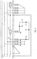
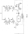
- Fig. 1 and 2 shown embodiment illustrates a drinking water installation on the example of a hotel or a hospital.
- a cold water line 2 On a floor schematically shown runs a cold water line 2 and parallel thereto, a hot water pipe 4 and a hot water circulation pipe 6 is provided.
- the hot water circulation pipe leads in a manner not shown, but generally known manner each individual wet cell 8.
- Each wet cell 8 also has a ring line 10 for cold water, which is connected to the cold water line 2 each.
- Each loop 10 has a plurality of consumers 12, which in the embodiment in the Fig. 1 and 2 are indicated schematically by a dot.
- the removal point 12a-d are connected in series in the ring line 10.
- the ring line 10 goes via a branch 14 from the cold water strand 2 and flows through an orifice 16 in this strand 2 a.
- the branch 14 of each individual ring line is upstream of the mouth 16 in the direction of flow (arrow S in the cold water line 2).
- From the corridor or the respective wet cell 8 are available in the loop 10 ball valves as full flow shut-off valves 18a, 18b provided, through which the connected thereto ring line 10 can be shut off from the cold water strand 2, for example, perform assembly work on the corresponding loop 10.
- valves 18, 20 are dead-space-free valves that meet the legal requirements that are placed on valves that are installed in drinking water systems.
- the valves comply with the European standard EN 13828 and the certification guideline according to DVGW worksheet W 570.
- the valves 18, 20 are provided as flush valves.
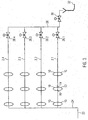
- Fig. 3 cold water pipes of a drinking water system are shown in a multi-storey house, for example a hospital.
- each single floor can water pipes according to the representations in the Fig. 1 and 2 be misplaced.
- This in Fig. 3 shown cold water line system has a transfer point 22 from the public drinking water supply network, extending in the vertical direction riser 24, from which in each floor a horizontally extending floor string 2 goes off, extending in the vertical connecting line 26, the interposition of a controllable valve 28 respectively to the individual floor strands 2 is connected and leads via a likewise controllable flush valve 30 to a discharge point 32 for used water to the public sewage disposal network.
- the individual cold water floor strands 2 run in a horizontal direction and one above the other.
- On each floor is a strand 2 intended.
- each strand 2 has six ring lines 10, which depart via branches 14 and mouths 16 of the individual strands 2 and open into them.
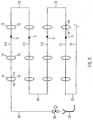
- Fig. 4 shown third embodiment, several laid in the vertical direction riser strings 2.1 to 2.4 are provided.
- shut-off valves 33 At the front end in the flow direction of the respective strands 2 are shut-off valves 33, which are provided between the individual strands 2.1 to 2.3 and a horizontal distribution line.
- the individual riser strands 2.1 to 2.4 enforce four superimposed floors in the embodiment shown.
- only a single wet cell 8 is shown schematically.
- all ring lines 10 are shown schematically.
- the underlying wet cells with the associated loops are not shown.
- the corresponding embodiment is indicated only by the mouth 16 provided on the floor.
- the controllable valves 28 At the end of the three left branches 2.1 to 2.3 are the controllable valves 28.
- valves 28 are provided between the individual strands 2.1 to 2.3 and a transverse line 36, whose distal end is connected to the last strand 2.4, which a falling in the vertical direction Flow leads and has at its end the purge valve 30, which leads to the discharge point.
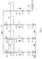
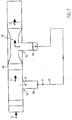
- Fig. 5 shown fourth embodiment of the present invention horizontally laid parallel floor strands 2 are provided, which are looped through. Accordingly, located at the end of each strand 2 a riser 35, which leads to the next floor strand 2 and is connected to the upstream end of the overlying floor strand 2 in the flow direction.
- the uppermost strand 2.4 terminates in a sewer line 26 provided with a purge valve 30 leading to the spent water discharge point 32.
- this flush valve 30 is located in a basement. However, it can be provided at any point behind the last loop 10 of the uppermost strand 2.4.
- a cold water circulation system with two parallel riser strands 2 is shown. Each individual riser 2 supplies per Floor two opposite wet cells 8 with cold water.
- the downstream end of the first, in Fig. 6 left strand 2.1 is connected via a transverse line 36 with the front end in the flow direction of the second right strand 2.2.
- the second riser 2.2 opens into a controllable flush valve 30, which leads to a discharge point 32 for spent water to the sewer.
- a tee is provided which leads to a circulation line 38 which comprises a pump 40 and a biological elimination unit 42 and connected via a further T-piece to the upstream end of the first riser string 2.1 is.
- the circulation line 38 can be closed by controllable control valves, for example.
- controllable control valves for example.
- the in Fig. 6 illustrated embodiment provided cold water from the transfer point 22 via the first riser 2.1, the transverse line 36 and through the second riser 2.2. If the flow is insufficient, the flushing valve 30 can be opened and any cold water in the piping system can be discharged to the sewage system.
- the pump 40 In the case of heavy soiling, it is possible to guide the water which is intrinsically in the line system by operating the pump 40 through the biological elimination unit 42 and to treat it there. Thereafter, the treated water can be returned to the system, but preferably discharged after opening the purge valve 30 via the sewer network.
- Fig. 7 schematically shows the connection of each ring line 10 shown schematically in the previous embodiments to the associated strand 2.
- Branch 14 and mouth 16 are provided on a uniform Ring Arthurs Seriesarmatur 44, which is designed as a branch and connection fitting.
- a branch piece 46 extends transversely to the direction of extension of the strand 2 from the ring-line flushing fitting 44.
- This branch pipe 46 is connected to the ring line 10.
- the rear end of the ring line 10 in the direction of flow is connected to a likewise extending transversely to the extension of the strand 2 return pipe 48.
- This return pipe 48 opens in the narrowed cross-section of a throttle 50, which is provided at the downstream end of the Ring Arthurs Seriesarmatur 44, or immediately thereafter.
- the branch pipe 46 and the return pipe 48 are spaced less than 30 cm apart.
- the throttle 50 is designed such that between the branch 14 and the mouth 16 a Pressure difference of about 20 to 50 mbar is set when, for example, provided at the respective end of the corresponding strand 2 valve 28 is operated for flushing the strand or a downstream sampling point. This pressure difference is sufficient to produce within the respective ring line 10 a circulating flushing flow '.
- a velocity of the flow S in the strand of about 1.5 m / second is assumed.
- the orifice 16, the branch 14 and the throttle 50 are designed such that approximately 10% of the flow S in the strand as loop flow R flush the respective ring line 10, whereas about 90% as the main flow H continue the line flush and in the throttle 50th be throttled
- the individual valves 28 can be controlled, for example, by a central control.
- the valves 28.1 to 28.4 are each first opened and closed in order to flush the respective ring lines in the strands 2.1 to 2.4 in the respective areas in succession.
- the flush valve 30 remains open in such a procedure, so that any contaminated water from the individual strands 2.1 to 2.4 can be discharged directly into the sewer system.
- the individual valves 28 can optionally also be dispensed with and all the strands 2.1 to 2.4 can be purged solely by opening the flushing valve 30.
- the in Fig. 3 The embodiment shown, however, is based on the finding that safe flushing can be ensured for each individual area solely by effectively shutting off and opening the individual strands 2.1 to 2.4.
- the individual vertical riser strands can be flushed in the same way.
- the right riser string 2.4 is flowed through and purged with each flush, which leads to the discharge point 32.
- Fig. 7 schematically illustrated training of branch 14 and mouth 16 leads each rinse of a single strand at least to a purge flow within the ring lines 10 of the associated strand 2.
- the design of branch 14, mouth 16 and throttle 50 is carried out to each individual ring line 10 of the system preferably in such a way that a targeted removal at a removal point 12, which is arranged on a downstream in the flow direction of the ring line, to a scavenging flow upstream of the ring lines in the direction of flow 10.
- a targeted removal at a removal point 12 which is arranged on a downstream in the flow direction of the ring line
- Fig. 4 shown third embodiment of the invention. If this is, for example, a hotel in which only the upper floor is occupied, it can be achieved by temporarily occupying all rooms in the top floor flushing the respectively arranged under the rooms ring lines 10 of the underlying room.
- the throttle is designed as a nozzle with fixed nozzle cross-sections and transitions.
- the throttle adjustable it may be preferable to make the throttle adjustable.
- the adjustment of the throttle should preferably be done automatically.
- Such a controllable throttle should preferably be connected to the central control unit. With such controllable throttles, for example, a hydraulic balancing between individual ring lines 10 or individual strands 2 can be achieved.
- the return line flush valve 44 shown schematically in the embodiments may also include the full-flow shut-off valves to minimize the assembly effort in the realization of the drinking water system.
- the formation of such a uniform fitting significantly reduces the assembly effort, since only at four points of the strand or the associated ring line must be connected to the valve.
Landscapes
- Engineering & Computer Science (AREA)
- General Engineering & Computer Science (AREA)
- Chemical & Material Sciences (AREA)
- Thermal Sciences (AREA)
- Combustion & Propulsion (AREA)
- Mechanical Engineering (AREA)
- Physics & Mathematics (AREA)
- Health & Medical Sciences (AREA)
- Life Sciences & Earth Sciences (AREA)
- Hydrology & Water Resources (AREA)
- Public Health (AREA)
- Water Supply & Treatment (AREA)
- Domestic Plumbing Installations (AREA)
- Pipeline Systems (AREA)
Priority Applications (1)
| Application Number | Priority Date | Filing Date | Title |
|---|---|---|---|
| PL07022601T PL1887150T3 (pl) | 2006-04-13 | 2007-04-13 | System wody pitnej i wody użytkowej oraz sposób eksploatacji takiego systemu |
Applications Claiming Priority (2)
| Application Number | Priority Date | Filing Date | Title |
|---|---|---|---|
| DE102006017807A DE102006017807B4 (de) | 2006-04-13 | 2006-04-13 | Trinkwassersystem sowie Verfahren zum Betrieb eines solchen Systems |
| EP07007597.3A EP1845207B1 (de) | 2006-04-13 | 2007-04-13 | Trinkwassersystem sowie Verfahren zum Betrieb eines solchen Systems |
Related Parent Applications (3)
| Application Number | Title | Priority Date | Filing Date |
|---|---|---|---|
| EP07007597.3A Division EP1845207B1 (de) | 2006-04-13 | 2007-04-13 | Trinkwassersystem sowie Verfahren zum Betrieb eines solchen Systems |
| EP07007597.3A Division-Into EP1845207B1 (de) | 2006-04-13 | 2007-04-13 | Trinkwassersystem sowie Verfahren zum Betrieb eines solchen Systems |
| EP07007597.3 Division | 2007-04-13 |
Publications (3)
| Publication Number | Publication Date |
|---|---|
| EP1887150A2 EP1887150A2 (de) | 2008-02-13 |
| EP1887150A3 EP1887150A3 (de) | 2013-03-06 |
| EP1887150B1 true EP1887150B1 (de) | 2016-09-14 |
Family
ID=37496678
Family Applications (3)
| Application Number | Title | Priority Date | Filing Date |
|---|---|---|---|
| EP07022601.4A Active EP1887150B1 (de) | 2006-04-13 | 2007-04-13 | Trink- und Brauchwassersystem sowie Verfahren zum Betrieb eines solchen Systems |
| EP07007597.3A Active EP1845207B1 (de) | 2006-04-13 | 2007-04-13 | Trinkwassersystem sowie Verfahren zum Betrieb eines solchen Systems |
| EP10010597.2A Active EP2264251B1 (de) | 2006-04-13 | 2007-04-13 | Trink- und Brauchwassersystem sowie Verfahren zum Betrieb eines solchen Systems |
Family Applications After (2)
| Application Number | Title | Priority Date | Filing Date |
|---|---|---|---|
| EP07007597.3A Active EP1845207B1 (de) | 2006-04-13 | 2007-04-13 | Trinkwassersystem sowie Verfahren zum Betrieb eines solchen Systems |
| EP10010597.2A Active EP2264251B1 (de) | 2006-04-13 | 2007-04-13 | Trink- und Brauchwassersystem sowie Verfahren zum Betrieb eines solchen Systems |
Country Status (5)
| Country | Link |
|---|---|
| EP (3) | EP1887150B1 (pl) |
| DE (1) | DE102006017807B4 (pl) |
| DK (2) | DK2264251T3 (pl) |
| PL (3) | PL2264251T3 (pl) |
| SI (2) | SI1845207T1 (pl) |
Families Citing this family (36)
| Publication number | Priority date | Publication date | Assignee | Title |
|---|---|---|---|---|
| US20100212750A1 (en) | 2007-11-07 | 2010-08-26 | Georg Fischer Llc | High Purity Water System |
| DE202008002822U1 (de) | 2008-02-28 | 2009-07-09 | Gebr.Kemper Gmbh + Co.Kg Metallwerke | Trink- und Brauchwasserversorgungseinrichtung eines Gebäudes und Steuervorrichtung für eine solche |
| DE202008003044U1 (de) | 2008-03-04 | 2008-05-08 | Gebr. Kemper Gmbh + Co. Kg | Anschlussarmatur |
| DE102008047938A1 (de) | 2008-09-18 | 2010-04-01 | Viega Gmbh & Co. Kg | Trinkwasserleitungssystem zur Erhaltung der Trinkwassergüte und Verfahren zum Betrieb eines solchen Trinkwasserleitungssystems |
| DE202009001030U1 (de) | 2009-01-27 | 2010-06-24 | Gebr. Kemper Gmbh & Co. Kg Metallwerke | Trink- oder Brauchwassersystem |
| DE202009003135U1 (de) | 2009-03-09 | 2010-09-02 | Gebr. Kemper Gmbh + Co. Kg | Trink- oder Brauchwassersystem |
| DE202010003376U1 (de) | 2010-03-09 | 2011-08-01 | Gebrüder Kemper GmbH + Co Metallwerke | Trink- und Brauchwassersystem |
| DE102010055176A1 (de) * | 2010-12-20 | 2012-07-12 | Honeywell Technologies Sarl | Trinkwasserversorgungssystem eines Gebäudes, Verfahren zum Betreiben desselben und Steuerungseinrichtung desselben |
| DE202011002327U1 (de) | 2011-02-03 | 2012-05-08 | Gebr. Kemper Gmbh + Co. Kg Metallwerke | Trink- und Brauchwassersystem |
| DE102011010840B4 (de) * | 2011-02-10 | 2019-08-14 | Oventrop Gmbh & Co. Kg | Trink- oder Brauchwassersystem |
| NL2007432C2 (nl) * | 2011-09-16 | 2013-03-19 | Genie B V | Leidingspoelsysteem voor ziektepreventie, en bijbehorende werkwijze en stuureenheid. |
| DE202012103128U1 (de) * | 2012-08-20 | 2013-11-22 | Hans Sasserath & Co. Kg | Anordnung zur Durchführung einer Hygienespülung in einer Wasserinstallation |
| DE102013015014A1 (de) | 2013-09-07 | 2015-03-12 | Gerd Haberland | Warmwasservorhaltung in Warmwasserversorgungsanlagen nach einer Zähleinrichtung |
| DE102014215408A1 (de) | 2014-08-05 | 2016-02-11 | Judo Wasseraufbereitung Gmbh | Multifunktionales Anschlusszwischenstück und Verwendungen des Anschlusszwischenstücks |
| DE202014007233U1 (de) | 2014-09-04 | 2015-12-09 | Gebr. Kemper Gmbh + Co. Kg Metallwerke | Steuervorrichtung und Trink- und/oder Brauchwassersystem mit einer solchen Steuervorrichtung |
| DE202015006366U1 (de) | 2015-09-07 | 2016-12-08 | Gebr. Kemper Gmbh + Co. Kg Metallwerke | Trink- und Brauchwasserversorgungseinrichtung eines Gebäudes und Regulierventil hierfür |
| DE202015007277U1 (de) | 2015-10-20 | 2017-01-23 | Gebr. Kemper Gmbh + Co. Kg Metallwerke | Trink- und Brauchwasserversorgungseinrichtung |
| DE102016103833A1 (de) | 2016-03-03 | 2017-09-07 | Uponor Innovation Ab | System und Verfahren zum Spülen einer Trinkwasserinstallation |
| DE102016118770A1 (de) | 2016-10-04 | 2018-04-05 | Schell Gmbh & Co. Kg | Vorrichtung zur Durchführung der Spülung von Leitungen einer Wasser-Gebäudeinstallation |
| DE202016106313U1 (de) | 2016-11-11 | 2018-02-14 | Gebr. Kemper Gmbh + Co. Kg Metallwerke | Wassersystem mit einem Durchflusserwärmer und einer Spülstation |
| DE102017105449A1 (de) * | 2017-03-14 | 2018-09-20 | Schell Gmbh & Co. Kg | Verfahren zur Steuerung eines Gebäudewasserversorgungssystems |
| DE202017007227U1 (de) * | 2017-03-27 | 2020-02-13 | Tece Gmbh | Hygienestation |
| CN111201353B (zh) | 2017-10-09 | 2021-12-31 | 维家技术有限及两合公司 | 具有声学传感器或存在报告器的饮用水供应系统、其控制方法和计算机程序 |
| DE202017006045U1 (de) | 2017-11-22 | 2019-02-25 | Gebr. Kemper Gmbh + Co. Kg Metallwerke | Vorrichtung zur Überwachung der Spülaktivitäten einer Wasserleitung |
| DE202017006304U1 (de) * | 2017-12-07 | 2019-03-08 | Gebr. Kemper Gmbh + Co. Kg Metallwerke | Selbstregulierender Differenzdruckregler für ein Trinkwassersystem und Trinkwassersystem mit einem solchen selbstregulierenden Differenzdruckregler |
| DE102018118910A1 (de) * | 2018-08-03 | 2020-02-06 | Aba Beul Gmbh | Spülmodul und Verfahren zum Spülen von Flüssigkeitsleitungen |
| DE202018003798U1 (de) * | 2018-08-16 | 2019-11-24 | Gebr. Kemper Gmbh + Co. Kg Metallwerke | Spülvorrichtung mit Generator |
| DE202018005578U1 (de) * | 2018-11-30 | 2020-03-04 | Gebr. Kemper Gmbh + Co. Kg Metallwerke | Trink- und Brauchwassersystem |
| EP3670765B1 (de) | 2018-12-19 | 2024-08-21 | Georg Fischer JRG AG | Warmwasserbereiterspeisung |
| DE102019201263A1 (de) * | 2019-01-31 | 2020-08-06 | Gebrüder Kemper Gmbh + Co. Kg Metallwerke | Trink- und Brauchwassersystem und Verfahren zum Spülen desselben |
| LU102008B1 (de) * | 2020-08-21 | 2022-02-21 | Wilo Se | Kompaktbaueinheit für eine Wasserzirkulation |
| DE202021101228U1 (de) * | 2021-03-11 | 2021-03-22 | Gebr. Kemper Gmbh + Co. Kg | Trinkwasser-Installation |
| DE202021104440U1 (de) | 2021-08-19 | 2021-09-03 | Gebr. Kemper Gmbh + Co. Kg | Trinkwasser-Installation |
| DE202023102295U1 (de) * | 2023-04-27 | 2024-08-01 | Gebr. Kemper Gmbh + Co. Kg | Trink- und Brauchwassersystem |
| DE202023105233U1 (de) | 2023-09-11 | 2024-12-13 | Gebr. Kemper Gmbh + Co. Kg | Trink- und Brauchwassersystem und Absperrventil dafür |
| WO2025119433A2 (de) | 2023-12-07 | 2025-06-12 | Viega Technology Gmbh & Co.Kg | Bereitstellungsverfahren zur bereitstellung von trinkwasser, trinkwasserversorgungsanordnung sowie warmwasser- und spülschalteinheit |
Citations (9)
| Publication number | Priority date | Publication date | Assignee | Title |
|---|---|---|---|---|
| DE8915477U1 (de) | 1989-06-10 | 1990-11-22 | Dürr GmbH, 7000 Stuttgart | Reinstwasserversorgungsvorrichtung |
| DE9302446U1 (de) | 1993-02-19 | 1993-04-01 | Lauer, Günter, 7850 Lörrach | Leitungsnetz, insbesondere Frisch- oder Reinwasser-Rohrleitungsnetz |
| US5518022A (en) | 1994-09-06 | 1996-05-21 | Ziehm; Raymond G. | Aspirator water circulation apparatus |
| US5622203A (en) | 1995-10-03 | 1997-04-22 | Moen Incorporated | Hot water circulation apparatus with adjustable venturi |
| EP0809079A1 (en) | 1996-05-20 | 1997-11-26 | Raymond G. Ziehm | Aspirator water circulation apparatus |
| DE19631403A1 (de) | 1996-08-04 | 1998-02-05 | Otto Kamp | Warmwasserversorgungsanlage |
| DE10031854A1 (de) | 2000-07-05 | 2002-01-17 | Immanuel Jeschke | Anlage zur stetigen Erneuerung des Trinkwassers in einer von einer Versorgungsleitung abzweigenden Anschlußleitung |
| US20050103693A1 (en) | 2003-11-14 | 2005-05-19 | Palm Joseph M. | Automatic flushing system and method for a potable water station |
| DE102005024252A1 (de) | 2005-05-27 | 2006-11-30 | tracemak GbR (vertretungsberechtigter Gesellschafter Siegfied Hötger, 48317 Drensteinfurt) | Leitungsanordnung, sowie Rohrleitungsanschlussstück und Rohrleitungsabschnitt |
Family Cites Families (2)
| Publication number | Priority date | Publication date | Assignee | Title |
|---|---|---|---|---|
| KR0124146B1 (ko) * | 1991-07-22 | 1997-11-25 | 요시시게 타까하시 | 유체 분배 시스템내의 유체 체류 방지장치 |
| DE10059255C1 (de) * | 2000-11-29 | 2002-08-14 | Otto Kamp | Trinkwasserversorgungsanlage |
-
2006
- 2006-04-13 DE DE102006017807A patent/DE102006017807B4/de not_active Expired - Lifetime
-
2007
- 2007-04-13 PL PL10010597T patent/PL2264251T3/pl unknown
- 2007-04-13 EP EP07022601.4A patent/EP1887150B1/de active Active
- 2007-04-13 EP EP07007597.3A patent/EP1845207B1/de active Active
- 2007-04-13 SI SI200731786A patent/SI1845207T1/sl unknown
- 2007-04-13 EP EP10010597.2A patent/EP2264251B1/de active Active
- 2007-04-13 PL PL07022601T patent/PL1887150T3/pl unknown
- 2007-04-13 DK DK10010597.2T patent/DK2264251T3/en active
- 2007-04-13 DK DK07022601.4T patent/DK1887150T3/en active
- 2007-04-13 PL PL07007597.3T patent/PL1845207T3/pl unknown
- 2007-04-13 SI SI200731835A patent/SI2264251T1/sl unknown
Patent Citations (9)
| Publication number | Priority date | Publication date | Assignee | Title |
|---|---|---|---|---|
| DE8915477U1 (de) | 1989-06-10 | 1990-11-22 | Dürr GmbH, 7000 Stuttgart | Reinstwasserversorgungsvorrichtung |
| DE9302446U1 (de) | 1993-02-19 | 1993-04-01 | Lauer, Günter, 7850 Lörrach | Leitungsnetz, insbesondere Frisch- oder Reinwasser-Rohrleitungsnetz |
| US5518022A (en) | 1994-09-06 | 1996-05-21 | Ziehm; Raymond G. | Aspirator water circulation apparatus |
| US5622203A (en) | 1995-10-03 | 1997-04-22 | Moen Incorporated | Hot water circulation apparatus with adjustable venturi |
| EP0809079A1 (en) | 1996-05-20 | 1997-11-26 | Raymond G. Ziehm | Aspirator water circulation apparatus |
| DE19631403A1 (de) | 1996-08-04 | 1998-02-05 | Otto Kamp | Warmwasserversorgungsanlage |
| DE10031854A1 (de) | 2000-07-05 | 2002-01-17 | Immanuel Jeschke | Anlage zur stetigen Erneuerung des Trinkwassers in einer von einer Versorgungsleitung abzweigenden Anschlußleitung |
| US20050103693A1 (en) | 2003-11-14 | 2005-05-19 | Palm Joseph M. | Automatic flushing system and method for a potable water station |
| DE102005024252A1 (de) | 2005-05-27 | 2006-11-30 | tracemak GbR (vertretungsberechtigter Gesellschafter Siegfied Hötger, 48317 Drensteinfurt) | Leitungsanordnung, sowie Rohrleitungsanschlussstück und Rohrleitungsabschnitt |
Non-Patent Citations (4)
| Title |
|---|
| "Trinkwasserinstallationen und Heizkörperanbindungen: Einzelanschluss oder Ringleitung?", IKZ PRAXIS, April 2001 (2001-04-01), pages 4ff, XP055393550 |
| "ViegaCAD für die Haustechnik", BENUTZERHANDBUCH, 1998, pages 1-11,236-245, XP055393552 |
| BEUTH-KOMMENTARE, KOMMENTAR ZU DIN 1988 TEILE 1 BIS 8, 1989, pages 413 - 415, XP055393556 |
| BOGER ET AL.: "Beuth-Kommentare - Kommentarr zu DIN 1988 Teile 1 bis 8", 1989, pages: 413 - 415, XP003023649 |
Also Published As
| Publication number | Publication date |
|---|---|
| EP1887150A2 (de) | 2008-02-13 |
| SI1845207T1 (sl) | 2016-07-29 |
| DE102006017807B4 (de) | 2013-10-24 |
| EP2264251B1 (de) | 2016-08-24 |
| SI2264251T1 (sl) | 2016-11-30 |
| EP2264251A3 (de) | 2013-03-06 |
| EP1845207A1 (de) | 2007-10-17 |
| PL1887150T3 (pl) | 2017-05-31 |
| DK2264251T3 (en) | 2016-11-07 |
| DK1887150T3 (en) | 2016-12-19 |
| EP1845207B1 (de) | 2016-05-11 |
| EP1887150A3 (de) | 2013-03-06 |
| DE102006017807A1 (de) | 2007-10-18 |
| PL2264251T3 (pl) | 2017-08-31 |
| PL1845207T3 (pl) | 2016-11-30 |
| EP2264251A2 (de) | 2010-12-22 |
Similar Documents
| Publication | Publication Date | Title |
|---|---|---|
| EP1887150B1 (de) | Trink- und Brauchwassersystem sowie Verfahren zum Betrieb eines solchen Systems | |
| EP2365141B1 (de) | Trink- oder Brauchwassersystem | |
| EP3337931B1 (de) | Vorrichtung und verfahren zum selbsttätigen spülen mit mehrfachventil | |
| EP2098645A1 (de) | Trink- und Brauchwassersystem | |
| EP2096214A2 (de) | Trink-Brauchwasserversorgungseinrichtung eines Gebäudes und Steuervorrichtung für eine solche | |
| EP1964983A1 (de) | Vorrichtung zum selbsttätigen Spülen von Wasserleitungen | |
| EP3695059A2 (de) | Trinkwasserversorgungssystem mit akustiksensor oder präsenzmelder, verfahren zu dessen steuerung sowie computerprogramm | |
| DE102013102567B4 (de) | Vorrichtung und Verfahren zur Verhinderung der Verkeimung von Wasserleitungen und Wasserabgabevorrichtungen | |
| DE102017101532A1 (de) | Warmwasserversorgungsanlage und Verfahren zum Betrieb dieser Warmwasserversorgungsanlage | |
| DE102019127158A1 (de) | Wasserversorgungsanlage und Verfahren zum Betrieb dieser Wasserversorgungsanlage | |
| EP2210985B1 (de) | Anschlussvorrichtung | |
| DE102019107179A1 (de) | Verfahren zur Wasserversorgung von mindestens einer Wasserentnahmestelle mit Kalt- und Warmwasser | |
| DE102018217228A1 (de) | Trinkwasserverteilungsmodul zum Verbinden einer Basisleitung mit einer Hauptzirkulationsleitung | |
| DE102017111073B4 (de) | Vorrichtung zur Spülung und/oder thermischen Desinfektion von Rohrleitungen | |
| DE102012004719A1 (de) | Verfahren zum Reinigen einer häuslichen Wasserleitung und/oder zur Aufrechterhaltung der Wasserqualität | |
| DE202006021088U1 (de) | Trink- und Brauchwassersystem | |
| DE19701847C2 (de) | Duscheinrichtung | |
| DE102015114469B3 (de) | System zur Führung von Kaltwasser, Verfahren zur Kühlung einer Kaltwasserstrecke und Verwendung einer Leitung zur Führung von Kaltwasser | |
| EP1457608A2 (de) | Brauseanordnung | |
| EP2845956B1 (de) | Trinkwasserinstallationsanordnung für Gebäude und Verfahren zum Teilentleeren einer Trinkwasserinstallationsanordnung | |
| EP3670765B1 (de) | Warmwasserbereiterspeisung | |
| EP2918738B1 (de) | Belüftungsvorrichtung für eine Steigleitung mit einer Einrichtung zum Vermindern von Stagnationswasser | |
| DE102019111486A1 (de) | Trinkwasser-Leitungsmodul zur Trinkwasserzirkulation bei geschlossenen Zapfstellen | |
| DE102015015649A1 (de) | Leitungsspülvorrichtung und leitungsspülsystem | |
| EP3363956A1 (de) | Vorrichtung zum selbsttätigen spülen |
Legal Events
| Date | Code | Title | Description |
|---|---|---|---|
| PUAI | Public reference made under article 153(3) epc to a published international application that has entered the european phase |
Free format text: ORIGINAL CODE: 0009012 |
|
| AC | Divisional application: reference to earlier application |
Ref document number: 1845207 Country of ref document: EP Kind code of ref document: P |
|
| AK | Designated contracting states |
Kind code of ref document: A2 Designated state(s): AT BE BG CH CY CZ DE DK EE ES FI FR GB GR HU IE IS IT LI LT LU LV MC MT NL PL PT RO SE SI SK TR |
|
| AX | Request for extension of the european patent |
Extension state: AL BA HR MK YU |
|
| PUAL | Search report despatched |
Free format text: ORIGINAL CODE: 0009013 |
|
| AK | Designated contracting states |
Kind code of ref document: A3 Designated state(s): AT BE BG CH CY CZ DE DK EE ES FI FR GB GR HU IE IS IT LI LT LU LV MC MT NL PL PT RO SE SI SK TR |
|
| AX | Request for extension of the european patent |
Extension state: AL BA HR MK RS |
|
| RIC1 | Information provided on ipc code assigned before grant |
Ipc: F24D 17/00 20060101ALI20130131BHEP Ipc: E03B 7/09 20060101ALI20130131BHEP Ipc: E03B 7/04 20060101AFI20130131BHEP |
|
| 17P | Request for examination filed |
Effective date: 20130612 |
|
| RBV | Designated contracting states (corrected) |
Designated state(s): AT BE BG CH CY CZ DE DK EE ES FI FR GB GR HU IE IS IT LI LT LU LV MC MT NL PL PT RO SE SI SK TR |
|
| AKX | Designation fees paid |
Designated state(s): AT BE BG CH CY CZ DE DK EE ES FI FR GB GR HU IE IS IT LI LT LU LV MC MT NL PL PT RO SE SI SK TR |
|
| GRAP | Despatch of communication of intention to grant a patent |
Free format text: ORIGINAL CODE: EPIDOSNIGR1 |
|
| INTG | Intention to grant announced |
Effective date: 20160310 |
|
| RBV | Designated contracting states (corrected) |
Designated state(s): AT BE BG CH CY CZ DK EE ES FI FR GB GR HU IE IS IT LI LT LU LV MC MT NL PL PT RO SE SI SK TR |
|
| REG | Reference to a national code |
Ref country code: DE Ref legal event code: R108 |
|
| GRAP | Despatch of communication of intention to grant a patent |
Free format text: ORIGINAL CODE: EPIDOSNIGR1 |
|
| INTG | Intention to grant announced |
Effective date: 20160616 |
|
| GRAS | Grant fee paid |
Free format text: ORIGINAL CODE: EPIDOSNIGR3 |
|
| GRAA | (expected) grant |
Free format text: ORIGINAL CODE: 0009210 |
|
| AC | Divisional application: reference to earlier application |
Ref document number: 1845207 Country of ref document: EP Kind code of ref document: P |
|
| AK | Designated contracting states |
Kind code of ref document: B1 Designated state(s): AT BE BG CH CY CZ DK EE ES FI FR GB GR HU IE IS IT LI LT LU LV MC MT NL PL PT RO SE SI SK TR |
|
| REG | Reference to a national code |
Ref country code: GB Ref legal event code: FG4D Free format text: NOT ENGLISH |
|
| REG | Reference to a national code |
Ref country code: CH Ref legal event code: NV Representative=s name: BOVARD AG, CH Ref country code: CH Ref legal event code: EP |
|
| REG | Reference to a national code |
Ref country code: IE Ref legal event code: FG4D Free format text: LANGUAGE OF EP DOCUMENT: GERMAN |
|
| REG | Reference to a national code |
Ref country code: AT Ref legal event code: REF Ref document number: 829164 Country of ref document: AT Kind code of ref document: T Effective date: 20161015 |
|
| REG | Reference to a national code |
Ref country code: NL Ref legal event code: FP |
|
| REG | Reference to a national code |
Ref country code: DK Ref legal event code: T3 Effective date: 20161215 |
|
| REG | Reference to a national code |
Ref country code: SE Ref legal event code: TRGR |
|
| REG | Reference to a national code |
Ref country code: LT Ref legal event code: MG4D |
|
| PG25 | Lapsed in a contracting state [announced via postgrant information from national office to epo] |
Ref country code: LT Free format text: LAPSE BECAUSE OF FAILURE TO SUBMIT A TRANSLATION OF THE DESCRIPTION OR TO PAY THE FEE WITHIN THE PRESCRIBED TIME-LIMIT Effective date: 20160914 |
|
| PG25 | Lapsed in a contracting state [announced via postgrant information from national office to epo] |
Ref country code: ES Free format text: LAPSE BECAUSE OF FAILURE TO SUBMIT A TRANSLATION OF THE DESCRIPTION OR TO PAY THE FEE WITHIN THE PRESCRIBED TIME-LIMIT Effective date: 20160914 Ref country code: LV Free format text: LAPSE BECAUSE OF FAILURE TO SUBMIT A TRANSLATION OF THE DESCRIPTION OR TO PAY THE FEE WITHIN THE PRESCRIBED TIME-LIMIT Effective date: 20160914 Ref country code: GR Free format text: LAPSE BECAUSE OF FAILURE TO SUBMIT A TRANSLATION OF THE DESCRIPTION OR TO PAY THE FEE WITHIN THE PRESCRIBED TIME-LIMIT Effective date: 20161215 |
|
| PG25 | Lapsed in a contracting state [announced via postgrant information from national office to epo] |
Ref country code: EE Free format text: LAPSE BECAUSE OF FAILURE TO SUBMIT A TRANSLATION OF THE DESCRIPTION OR TO PAY THE FEE WITHIN THE PRESCRIBED TIME-LIMIT Effective date: 20160914 Ref country code: RO Free format text: LAPSE BECAUSE OF FAILURE TO SUBMIT A TRANSLATION OF THE DESCRIPTION OR TO PAY THE FEE WITHIN THE PRESCRIBED TIME-LIMIT Effective date: 20160914 |
|
| REG | Reference to a national code |
Ref country code: FR Ref legal event code: PLFP Year of fee payment: 11 |
|
| PG25 | Lapsed in a contracting state [announced via postgrant information from national office to epo] |
Ref country code: BG Free format text: LAPSE BECAUSE OF FAILURE TO SUBMIT A TRANSLATION OF THE DESCRIPTION OR TO PAY THE FEE WITHIN THE PRESCRIBED TIME-LIMIT Effective date: 20161214 Ref country code: IS Free format text: LAPSE BECAUSE OF FAILURE TO SUBMIT A TRANSLATION OF THE DESCRIPTION OR TO PAY THE FEE WITHIN THE PRESCRIBED TIME-LIMIT Effective date: 20170114 Ref country code: PT Free format text: LAPSE BECAUSE OF FAILURE TO SUBMIT A TRANSLATION OF THE DESCRIPTION OR TO PAY THE FEE WITHIN THE PRESCRIBED TIME-LIMIT Effective date: 20170116 |
|
| REG | Reference to a national code |
Ref country code: SK Ref legal event code: T3 Ref document number: E 22941 Country of ref document: SK |
|
| PG25 | Lapsed in a contracting state [announced via postgrant information from national office to epo] |
Ref country code: IT Free format text: LAPSE BECAUSE OF FAILURE TO SUBMIT A TRANSLATION OF THE DESCRIPTION OR TO PAY THE FEE WITHIN THE PRESCRIBED TIME-LIMIT Effective date: 20160914 |
|
| PLBI | Opposition filed |
Free format text: ORIGINAL CODE: 0009260 |
|
| PLAX | Notice of opposition and request to file observation + time limit sent |
Free format text: ORIGINAL CODE: EPIDOSNOBS2 |
|
| 26 | Opposition filed |
Opponent name: VIEGA TECHNOLOGY GMBH & CO. KG Effective date: 20170614 Opponent name: GEORG FISCHER JRG AG Effective date: 20170531 |
|
| PLBB | Reply of patent proprietor to notice(s) of opposition received |
Free format text: ORIGINAL CODE: EPIDOSNOBS3 |
|
| PG25 | Lapsed in a contracting state [announced via postgrant information from national office to epo] |
Ref country code: MC Free format text: LAPSE BECAUSE OF FAILURE TO SUBMIT A TRANSLATION OF THE DESCRIPTION OR TO PAY THE FEE WITHIN THE PRESCRIBED TIME-LIMIT Effective date: 20160914 |
|
| REG | Reference to a national code |
Ref country code: FR Ref legal event code: PLFP Year of fee payment: 12 |
|
| PG25 | Lapsed in a contracting state [announced via postgrant information from national office to epo] |
Ref country code: MT Free format text: LAPSE BECAUSE OF FAILURE TO SUBMIT A TRANSLATION OF THE DESCRIPTION OR TO PAY THE FEE WITHIN THE PRESCRIBED TIME-LIMIT Effective date: 20160914 |
|
| PLCK | Communication despatched that opposition was rejected |
Free format text: ORIGINAL CODE: EPIDOSNREJ1 |
|
| STAA | Information on the status of an ep patent application or granted ep patent |
Free format text: STATUS: THE PATENT HAS BEEN GRANTED |
|
| APBM | Appeal reference recorded |
Free format text: ORIGINAL CODE: EPIDOSNREFNO |
|
| APBP | Date of receipt of notice of appeal recorded |
Free format text: ORIGINAL CODE: EPIDOSNNOA2O |
|
| APAH | Appeal reference modified |
Free format text: ORIGINAL CODE: EPIDOSCREFNO |
|
| APAW | Appeal reference deleted |
Free format text: ORIGINAL CODE: EPIDOSDREFNO |
|
| APBM | Appeal reference recorded |
Free format text: ORIGINAL CODE: EPIDOSNREFNO |
|
| APBP | Date of receipt of notice of appeal recorded |
Free format text: ORIGINAL CODE: EPIDOSNNOA2O |
|
| APBQ | Date of receipt of statement of grounds of appeal recorded |
Free format text: ORIGINAL CODE: EPIDOSNNOA3O |
|
| PGFP | Annual fee paid to national office [announced via postgrant information from national office to epo] |
Ref country code: PL Payment date: 20190326 Year of fee payment: 13 |
|
| PG25 | Lapsed in a contracting state [announced via postgrant information from national office to epo] |
Ref country code: HU Free format text: LAPSE BECAUSE OF FAILURE TO SUBMIT A TRANSLATION OF THE DESCRIPTION OR TO PAY THE FEE WITHIN THE PRESCRIBED TIME-LIMIT; INVALID AB INITIO Effective date: 20070413 |
|
| PGFP | Annual fee paid to national office [announced via postgrant information from national office to epo] |
Ref country code: BG Payment date: 20190424 Year of fee payment: 13 Ref country code: TR Payment date: 20190411 Year of fee payment: 13 |
|
| PG25 | Lapsed in a contracting state [announced via postgrant information from national office to epo] |
Ref country code: CY Free format text: LAPSE BECAUSE OF NON-PAYMENT OF DUE FEES Effective date: 20160914 |
|
| PG25 | Lapsed in a contracting state [announced via postgrant information from national office to epo] |
Ref country code: FR Free format text: LAPSE BECAUSE OF NON-PAYMENT OF DUE FEES Effective date: 20200430 |
|
| PGFP | Annual fee paid to national office [announced via postgrant information from national office to epo] |
Ref country code: FI Payment date: 20210427 Year of fee payment: 15 |
|
| PGFP | Annual fee paid to national office [announced via postgrant information from national office to epo] |
Ref country code: SI Payment date: 20210322 Year of fee payment: 15 |
|
| APBU | Appeal procedure closed |
Free format text: ORIGINAL CODE: EPIDOSNNOA9O |
|
| PLBN | Opposition rejected |
Free format text: ORIGINAL CODE: 0009273 |
|
| STAA | Information on the status of an ep patent application or granted ep patent |
Free format text: STATUS: OPPOSITION REJECTED |
|
| 27O | Opposition rejected |
Effective date: 20211012 |
|
| PGFP | Annual fee paid to national office [announced via postgrant information from national office to epo] |
Ref country code: SK Payment date: 20220321 Year of fee payment: 16 Ref country code: CZ Payment date: 20220322 Year of fee payment: 16 |
|
| PG25 | Lapsed in a contracting state [announced via postgrant information from national office to epo] |
Ref country code: TR Free format text: LAPSE BECAUSE OF NON-PAYMENT OF DUE FEES Effective date: 20200413 |
|
| PGFP | Annual fee paid to national office [announced via postgrant information from national office to epo] |
Ref country code: SE Payment date: 20220425 Year of fee payment: 16 |
|
| PG25 | Lapsed in a contracting state [announced via postgrant information from national office to epo] |
Ref country code: PL Free format text: LAPSE BECAUSE OF NON-PAYMENT OF DUE FEES Effective date: 20200413 |
|
| PG25 | Lapsed in a contracting state [announced via postgrant information from national office to epo] |
Ref country code: FI Free format text: LAPSE BECAUSE OF NON-PAYMENT OF DUE FEES Effective date: 20220413 |
|
| REG | Reference to a national code |
Ref country code: SI Ref legal event code: KO00 Effective date: 20221208 |
|
| PG25 | Lapsed in a contracting state [announced via postgrant information from national office to epo] |
Ref country code: SI Free format text: LAPSE BECAUSE OF NON-PAYMENT OF DUE FEES Effective date: 20220414 |
|
| REG | Reference to a national code |
Ref country code: SE Ref legal event code: EUG |
|
| REG | Reference to a national code |
Ref country code: SK Ref legal event code: MM4A Ref document number: E 22941 Country of ref document: SK Effective date: 20230413 |
|
| PG25 | Lapsed in a contracting state [announced via postgrant information from national office to epo] |
Ref country code: SK Free format text: LAPSE BECAUSE OF NON-PAYMENT OF DUE FEES Effective date: 20230413 |
|
| PG25 | Lapsed in a contracting state [announced via postgrant information from national office to epo] |
Ref country code: SK Free format text: LAPSE BECAUSE OF NON-PAYMENT OF DUE FEES Effective date: 20230413 Ref country code: SE Free format text: LAPSE BECAUSE OF NON-PAYMENT OF DUE FEES Effective date: 20230414 Ref country code: CZ Free format text: LAPSE BECAUSE OF NON-PAYMENT OF DUE FEES Effective date: 20230413 |
|
| P01 | Opt-out of the competence of the unified patent court (upc) registered |
Effective date: 20240304 |
|
| PGFP | Annual fee paid to national office [announced via postgrant information from national office to epo] |
Ref country code: NL Payment date: 20250426 Year of fee payment: 19 |
|
| PGFP | Annual fee paid to national office [announced via postgrant information from national office to epo] |
Ref country code: LU Payment date: 20250426 Year of fee payment: 19 |
|
| PGFP | Annual fee paid to national office [announced via postgrant information from national office to epo] |
Ref country code: DK Payment date: 20250429 Year of fee payment: 19 Ref country code: GB Payment date: 20250426 Year of fee payment: 19 |
|
| PGFP | Annual fee paid to national office [announced via postgrant information from national office to epo] |
Ref country code: BE Payment date: 20250426 Year of fee payment: 19 |
|
| PGFP | Annual fee paid to national office [announced via postgrant information from national office to epo] |
Ref country code: CH Payment date: 20250501 Year of fee payment: 19 |
|
| PGFP | Annual fee paid to national office [announced via postgrant information from national office to epo] |
Ref country code: AT Payment date: 20250424 Year of fee payment: 19 |
|
| PGFP | Annual fee paid to national office [announced via postgrant information from national office to epo] |
Ref country code: IE Payment date: 20250424 Year of fee payment: 19 |