EP1885136A2 - Appareil de traitement des images, appareil de photo, procédé de traitement des images, et produit de programme informatique - Google Patents
Appareil de traitement des images, appareil de photo, procédé de traitement des images, et produit de programme informatique Download PDFInfo
- Publication number
- EP1885136A2 EP1885136A2 EP07252794A EP07252794A EP1885136A2 EP 1885136 A2 EP1885136 A2 EP 1885136A2 EP 07252794 A EP07252794 A EP 07252794A EP 07252794 A EP07252794 A EP 07252794A EP 1885136 A2 EP1885136 A2 EP 1885136A2
- Authority
- EP
- European Patent Office
- Prior art keywords
- information
- image
- unit
- luminance
- noise
- Prior art date
- Legal status (The legal status is an assumption and is not a legal conclusion. Google has not performed a legal analysis and makes no representation as to the accuracy of the status listed.)
- Granted
Links
- 238000003384 imaging method Methods 0.000 title claims description 112
- 238000012545 processing Methods 0.000 title claims description 95
- 238000003672 processing method Methods 0.000 title claims description 9
- 238000004590 computer program Methods 0.000 title claims description 3
- 230000002194 synthesizing effect Effects 0.000 claims abstract description 63
- 239000000284 extract Substances 0.000 claims abstract description 10
- 230000035945 sensitivity Effects 0.000 claims description 31
- 238000000034 method Methods 0.000 description 81
- 230000008569 process Effects 0.000 description 64
- 238000000605 extraction Methods 0.000 description 43
- 230000000694 effects Effects 0.000 description 30
- 230000000875 corresponding effect Effects 0.000 description 22
- 230000006870 function Effects 0.000 description 21
- 238000000926 separation method Methods 0.000 description 17
- 230000015654 memory Effects 0.000 description 15
- 238000010586 diagram Methods 0.000 description 14
- 238000006243 chemical reaction Methods 0.000 description 11
- 238000009499 grossing Methods 0.000 description 11
- 101100115215 Caenorhabditis elegans cul-2 gene Proteins 0.000 description 8
- 230000003287 optical effect Effects 0.000 description 8
- 238000005516 engineering process Methods 0.000 description 6
- 238000012937 correction Methods 0.000 description 5
- 230000006835 compression Effects 0.000 description 4
- 238000007906 compression Methods 0.000 description 4
- 230000006837 decompression Effects 0.000 description 4
- 230000003247 decreasing effect Effects 0.000 description 3
- 230000000295 complement effect Effects 0.000 description 2
- 238000001914 filtration Methods 0.000 description 2
- 239000004065 semiconductor Substances 0.000 description 2
- 230000003321 amplification Effects 0.000 description 1
- 230000008859 change Effects 0.000 description 1
- 238000004891 communication Methods 0.000 description 1
- 230000002596 correlated effect Effects 0.000 description 1
- 238000013500 data storage Methods 0.000 description 1
- 239000004973 liquid crystal related substance Substances 0.000 description 1
- 229910044991 metal oxide Inorganic materials 0.000 description 1
- 150000004706 metal oxides Chemical class 0.000 description 1
- 238000012986 modification Methods 0.000 description 1
- 230000004048 modification Effects 0.000 description 1
- 238000003199 nucleic acid amplification method Methods 0.000 description 1
- 238000011084 recovery Methods 0.000 description 1
- 238000005070 sampling Methods 0.000 description 1
- 230000001360 synchronised effect Effects 0.000 description 1
Images


Classifications
-
- H—ELECTRICITY
- H04—ELECTRIC COMMUNICATION TECHNIQUE
- H04N—PICTORIAL COMMUNICATION, e.g. TELEVISION
- H04N9/00—Details of colour television systems
- H04N9/64—Circuits for processing colour signals
- H04N9/646—Circuits for processing colour signals for image enhancement, e.g. vertical detail restoration, cross-colour elimination, contour correction, chrominance trapping filters
-
- G—PHYSICS
- G06—COMPUTING; CALCULATING OR COUNTING
- G06T—IMAGE DATA PROCESSING OR GENERATION, IN GENERAL
- G06T5/00—Image enhancement or restoration
- G06T5/20—Image enhancement or restoration by the use of local operators
-
- G—PHYSICS
- G06—COMPUTING; CALCULATING OR COUNTING
- G06T—IMAGE DATA PROCESSING OR GENERATION, IN GENERAL
- G06T5/00—Image enhancement or restoration
- G06T5/50—Image enhancement or restoration by the use of more than one image, e.g. averaging, subtraction
-
- G06T5/70—
-
- G—PHYSICS
- G06—COMPUTING; CALCULATING OR COUNTING
- G06T—IMAGE DATA PROCESSING OR GENERATION, IN GENERAL
- G06T7/00—Image analysis
- G06T7/10—Segmentation; Edge detection
- G06T7/13—Edge detection
-
- H—ELECTRICITY
- H04—ELECTRIC COMMUNICATION TECHNIQUE
- H04N—PICTORIAL COMMUNICATION, e.g. TELEVISION
- H04N1/00—Scanning, transmission or reproduction of documents or the like, e.g. facsimile transmission; Details thereof
- H04N1/40—Picture signal circuits
- H04N1/409—Edge or detail enhancement; Noise or error suppression
-
- H—ELECTRICITY
- H04—ELECTRIC COMMUNICATION TECHNIQUE
- H04N—PICTORIAL COMMUNICATION, e.g. TELEVISION
- H04N1/00—Scanning, transmission or reproduction of documents or the like, e.g. facsimile transmission; Details thereof
- H04N1/46—Colour picture communication systems
-
- H—ELECTRICITY
- H04—ELECTRIC COMMUNICATION TECHNIQUE
- H04N—PICTORIAL COMMUNICATION, e.g. TELEVISION
- H04N5/00—Details of television systems
- H04N5/14—Picture signal circuitry for video frequency region
-
- H—ELECTRICITY
- H04—ELECTRIC COMMUNICATION TECHNIQUE
- H04N—PICTORIAL COMMUNICATION, e.g. TELEVISION
- H04N9/00—Details of colour television systems
- H04N9/77—Circuits for processing the brightness signal and the chrominance signal relative to each other, e.g. adjusting the phase of the brightness signal relative to the colour signal, correcting differential gain or differential phase
- H04N9/78—Circuits for processing the brightness signal and the chrominance signal relative to each other, e.g. adjusting the phase of the brightness signal relative to the colour signal, correcting differential gain or differential phase for separating the brightness signal or the chrominance signal from the colour television signal, e.g. using comb filter
-
- G—PHYSICS
- G06—COMPUTING; CALCULATING OR COUNTING
- G06T—IMAGE DATA PROCESSING OR GENERATION, IN GENERAL
- G06T2207/00—Indexing scheme for image analysis or image enhancement
- G06T2207/10—Image acquisition modality
- G06T2207/10024—Color image
-
- G—PHYSICS
- G06—COMPUTING; CALCULATING OR COUNTING
- G06T—IMAGE DATA PROCESSING OR GENERATION, IN GENERAL
- G06T2207/00—Indexing scheme for image analysis or image enhancement
- G06T2207/20—Special algorithmic details
- G06T2207/20172—Image enhancement details
- G06T2207/20192—Edge enhancement; Edge preservation
-
- H—ELECTRICITY
- H04—ELECTRIC COMMUNICATION TECHNIQUE
- H04N—PICTORIAL COMMUNICATION, e.g. TELEVISION
- H04N5/00—Details of television systems
- H04N5/14—Picture signal circuitry for video frequency region
- H04N5/21—Circuitry for suppressing or minimising disturbance, e.g. moiré or halo
Definitions
- the present invention relates to an image processing apparatus, an imaging apparatus, an image processing method, and a computer program product.
- an imaging apparatus in which pixels of a plurality of images are added is disclosed (see Japanese Patent Application Laid-Open No. 2005-44915 ). In such an imaging apparatus, pixels of images are added to increase sensitivity.
- Another imaging apparatus is disclosed (see Japanese Patent Application Laid-Open No. 2005-303519 ) in which a pixel signal for adding pixel values of adjacent pixels together is output to increase sensitivity.
- a technology is also disclosed (see Japanese Patent Application Laid-Open No. 2004-297731 ) in which, although noise is enhanced when an image is shot with increased sensitivity, a cut-off frequency of a low-pass filter is set according to imaging sensitivity to remove noise.
- An image processing apparatus includes an image-information obtaining unit that obtains image information; an image-component separating unit that separates the image information obtained by the image-information obtaining unit into luminance information and color information; an edge extracting unit that extracts edge information from the luminance information separated by the image-component separating unit; a luminance-noise removing unit that removes noise from the luminance information separated by the image-component separating unit; a color-noise removing unit that removes noise from the color information separated by the image-component separating unit; and an image-information synthesizing unit that synthesizes image information based on the edge information extracted by the edge extracting unit, the luminance information from which the noise is removed by the luminance-noise removing unit, and the color information from which the noise is removed by the color-noise removing unit.
- An image processing apparatus includes an image-information obtaining unit that obtains image information; a highly-sensitive low-resolution image generating unit that generates highly-sensitive low-resolution image information by adding a plurality of adjacent pixel values in the image information obtained by the image-information obtaining unit to produce one pixel value; a scaling unit that scales up or down the highly-sensitive low-resolution image information generated by the highly-sensitive low-resolution image generating unit; and an image-information synthesizing unit that synthesizes image information from the image information obtained by the image-information obtaining unit and the highly-sensitive low-resolution image information scaled up or down by the scaling unit.
- An image processing method includes obtaining image information; separating the image information obtained at the obtaining into luminance information and color information; extracting edge information from the luminance information separated at the separating; luminance-noise removing including removing noise from the luminance information separated at the separating; color-noise removing including removing noise from the color information separated at the separating; and synthesizing image information based on the edge information extracted at the extracting, the luminance information from which the noise is removed at the luminance-noise removing, and the color information from which the noise is removed at the color-noise removing.
- An image processing method includes obtaining image information; separating the image information obtained at the obtaining into luminance information and color information; extracting edge information from the luminance information separated at the separating; performing a scaling on the luminance information and the color information separated at the separating; luminance-noise removing including removing noise from the luminance information on which the scaling is performed at the scaling; color-noise removing including removing noise from the color information on which the scaling is performed at the scaling; and synthesizing image information based on the edge information extracted at the extracting, the luminance information from which the noise is removed at the luminance-noise removing, and the color information from which the noise is removed at the color-noise removing.
- An image processing method includes obtaining image information; generating highly-sensitive low-resolution image information by adding a plurality of adjacent pixel values in the image information obtained at the obtaining to produce one pixel value; scaling up or down the highly-sensitive low-resolution image information generated at the generating; and synthesizing image information from the image information obtained at the obtaining unit and the highly-sensitive low-resolution image information scaled up or down at the scaling.
- Fig. 1 is a block diagram of the configuration of an image processing unit 100 according to the first embodiment.
- the image processing unit 100 includes an image-information obtaining unit 101, a component separating unit 102, an imaging-condition obtaining unit 103, a filter determining unit 104, a luminance-component edge extracting unit 110, a luminance-component noise removing unit 105, a color-component noise removing unit 106, an image-information synthesizing unit 107, an image-information compressing unit 108, an image-information output unit 109, an edge-extraction-filter size database 120, a parameter database 130, a noise-removal-filter size database 140, and a Gaussian ⁇ -value database 150.
- the edge extraction filter size is a size of a filter for use in extracting an edge from image information.
- An optimum size of the filter for use in edge extraction varies depending on the imaging condition.
- the edge-extraction-filter size database 120 stores an optimum filter size for each imaging condition.
- Fig. 2 is a table for explaining an example of a data structure of an edge-extraction-filter size database. In this manner, in the edge-extraction-filter size database 120, imaging conditions and edge extraction filter sizes are associated with each other. Therefore, an optimum filter size can be determined from the imaging condition.
- the imaging condition is a condition that influences edge extraction in an image shot by the digital camera.
- sensitivity of the camera, exposure time, and temperature at shooting are defined as imaging conditions.
- the sensitivity of the camera indicates the sensitivity of a CCD or complementary metal oxide semiconductor (CMOS) sensor. As the sensitivity is higher, the shutter speed is higher, camera shake tends not to occur, and a moving subject can be shot without blurring. Furthermore, a bright image can be shot even at a dark place. On the other hand, if the sensitivity is increased, noise tends to occur.
- the exposure time indicates a time during which light is applied to the CCD or CMOS sensor. If the sensitivity is high, an image can be shot even with a decreased exposure time.
- the temperature at shooting indicates an outside air temperature at the time of shooting by camera. As the temperature is lower, noise tends not to occur.
- the sensitivity of camera, exposure time, and temperature at shooting are taken as imaging conditions.
- the imaging conditions are not meant to be restricted to those above, and are arbitrary as long as they change edge extraction.
- the parameter database 130 stores ⁇ values and k values for calculating a value of a Laplacian of Gaussian (LoG) filter for edge extraction corresponding to the imaging condition.
- Fig. 3 is a table for explaining an example of a data structure of the parameter database.
- the parameter database 130 stores the imaging conditions, ⁇ values and k values for calculating a value of the LoG filter in association with each other.
- the ⁇ value indicates a parameter that determines a width of the filter. As the ⁇ value is larger, the width of the filter is wider, and the smoothing effect is larger. As the ⁇ value is smaller, the width of the filter is narrower, and the effect of edge enhancement is stronger.
- the k value indicates a parameter representing a strength of edge enhancement. As the k value is larger, the effect of edge enhancement is larger. As the k value is smaller, the effect of blur recovery is smaller. In this manner, with the ⁇ value and k value being changed, the correction result can be adjusted.
- the ⁇ value of the LoG filter is closer to zero, the filter is more analogous to a Laplacian filter.
- the edge extraction filter is found not only from the LoG function. Alternatively, a filter found from another function may be used for performing an edge extraction process.
- the noise-removal-filter size database 140 stores a filter size for noise removal corresponding to the imaging condition.
- Fig. 4 is a table for explaining an example of a data structure of a noise-removal-filter size database.
- the noise-removal-filter size database 140 stores the imaging conditions and filter sizes in association with each other.
- the filter size indicates a size of a noise removal filter specified by the imaging condition, and a filter size is stored for each of luminance information and color information. As the filter size is larger, the effect of noise removal is larger, but edge burring is larger. That is, the noise removal effect and edge blurring have a trade-off relation. Since the noise level of the shot image varies depending on the imaging condition, the filter size is selected according to the imaging condition at the time of shooting, thereby performing optimum noise removal.
- Image information in YUV format is formed of luminance information (Y) and color information (U, V).
- the luminance information indicates a value approximately proportional to the strength sensed by human eyes as "luminance".
- luminance In the color information (U, V), U represents hue and chroma of blue series, and V represents those of red series. For each of the luminance information and the color information, a corresponding noise removal process is performed, thereby optimally removing noise.
- first size information indicating a size of a luminance filter and second size information indicating a size of a color filter store the same size.
- the size of the luminance filter indicated by the first size information may be smaller than the size of the color filter indicated by the second size information.
- the Gaussian ⁇ -value database 150 stores ⁇ values for calculating a value of a Gaussian smoothing filter for noise removal corresponding to the imaging condition.
- Fig. 5 is a table for explaining an example of a data structure of a Gaussian ⁇ -value database.
- the Gaussian ⁇ -value database 150 stores the imaging conditions and ⁇ values for calculating values of a Gaussian smoothing filter in association with each other.
- the magnitude of the ⁇ value represents the strength of noise removal. As the ⁇ value is larger, the noise removal effect is larger.
- the filter is found not only from the Gaussian function. Alternatively, a filter found from another function may be used for performing a noise removal process.
- the image-information obtaining unit 101 obtains image information from temporary-storage memory.
- the obtained image information is image information converted to YUV format.
- the component separating unit 102 separates the image information in YUV format obtained by the image-information obtaining unit 101 into luminance information (Y) and color information (U, V).
- the imaging-condition obtaining unit 103 obtains an imaging condition corresponding to the image information obtained by the image-information obtaining unit 101 from the temporary-storage memory.
- This imaging condition is an imaging condition at the time of shooting, that is, the sensitivity of camera, exposure time, and temperature at shooting, and they are stored in association with each other.
- the imaging condition at the time of shooting may be stored as part of the image information.
- the filter determining unit 104 determines an edge extraction filter and noise removal filters (a luminance filter and a color filter) corresponding to the imaging condition. First, the filter determining unit 104 specifies, from the edge-extraction-filter size database 120, the size of an edge extraction filter associated with the imaging condition obtained by the imaging-condition obtaining unit 103, and specifies, from the parameter database 130, a ⁇ value and k value of the LoG function associated with the imaging condition obtained by the imaging-condition obtaining unit 103.
- the filter determining unit 104 further uses the edge extraction filter size and the ⁇ value of the LoG function to calculate an edge extraction filter by using the following equation (1).
- LoG x ⁇ y - 1 ⁇ ⁇ ⁇ 4 [ 1 - x 2 + y 2 2 ⁇ ⁇ 2 ] e x 2 + y 2 2 ⁇ ⁇ 2
- the filter determining unit 104 determines noise removal filters corresponding to the imaging condition.
- the filter determining unit 104 specifies, from the noise-removal-filter size database 140, the size of noise removal filters associated with the imaging condition obtained by the imaging-condition obtaining unit 103, that is, the size of a luminance filter for removing noise from the luminance information and the size of a color filter for removing noise from the color information.
- the filter determining unit 104 specifies, from the Gaussian ⁇ -value database 150, the ⁇ value of the Gaussian function associated with the imaging condition obtained by the imaging-condition obtaining unit 103.
- the filter determining unit 104 further uses the size of the luminance filter and the ⁇ value of the Gaussian function to calculate a luminance filter (Gaussian smoothing filter) by using the following equation (2).
- G x ⁇ y 1 2 ⁇ ⁇ ⁇ ⁇ 2 ⁇ e x 2 + y 2 2 ⁇ ⁇ 2
- the filter determining unit 104 uses the size of the color filter and the ⁇ value of the Gaussian function to calculate a color filter (Gaussian smoothing filter) by using the equation (2) mentioned above.
- the luminance-component edge extracting unit 110 uses the edge extraction filter determined by the filter determining unit 104 and the k value to extract edge information from the luminance information.
- the luminance-component noise removing unit 105 uses the noise removal filter determined by the filter determining unit 104, that is, the luminance filter (low-pass filter), to remove noise from the luminance information.
- the color-component noise removing unit 106 uses the noise removal filter determined by the filter determining unit 104, that is, the color filter (low-pass filter), to remove noise from the color information.
- the image-information synthesizing unit 107 combines the edge information extracted from the luminance-component edge extracting unit 110, the luminance information with noise removed therefrom by the luminance-component noise removing unit 105, and the color information with noise removed therefrom by the color-component noise removing unit 106 to generate image information in YUV format.
- the image-information synthesizing unit 107 forms an image-information generating unit according to the present invention.
- s x ⁇ y f s x ⁇ y - k ⁇ loG x ⁇ y ⁇ f x ⁇ y
- fs(x,y) represents a luminance-component subjected to a noise-removal filter process
- s(x,y) represents a synthetic image.
- the luminance information calculated with the equation (4) is further combined with the color information to generate image information.
- the image information in YUV format may be further converted to image information in another format, for example, in RGB format.
- the image-information compressing unit 108 compresses the image information in YUV format synthesized by the image-information synthesizing unit 107 to, for example, Joint Photographic Experts Group (JPEG) format.
- the image-information output unit 109 outputs the image information compressed by the image-information compressing unit 108 to a memory card or the like.
- FIGs. 6A and 6B depict a flowchart of the image processing procedure performed by the image-information obtaining unit, the component separating unit, the imaging-condition obtaining unit, the filter determining unit, the luminance-component edge extracting unit, the luminance-component noise removing unit, the color-component noise removing unit, the image-information synthesizing unit, the image-information compressing unit, and the image-information output unit.
- the image-information obtaining unit 101 obtains image information in YUV format from temporary-storage memory (step S601).
- the component separating unit 102 separates the image information in YUV format obtained by the image-information obtaining unit 101 into luminance information and color information (step S602).
- the imaging-condition obtaining unit 103 obtains the imaging condition associated with the image information (step S603).
- the filter determining unit 104 specifies, from the edge-extraction-filter size database 120, the size of an edge extraction filter corresponding to the imaging condition obtained by the imaging-condition obtaining unit 103 (step S604). For example, 5x5 is specified as the size of the edge extraction filter.
- the filter determining unit 104 specifies, from the parameter database 130, a ⁇ value and k value of the LoG function corresponding to the imaging condition obtained by the imaging-condition obtaining unit 103 (step S605).
- the filter determining unit 104 determines each value of the edge extraction filter from the filter size of the edge extraction filter and the ⁇ value and k value of the LoG function (step S606).
- Fig. 7 depicts an example of the edge extraction filter with a filter size of 5 ⁇ 5.
- Ai which is a value of the edge extraction filter, is a value calculated by the equation (1).
- the luminance-component edge extracting unit 110 uses the edge extraction filter determined by the filter determining unit 104 to extract edge information from the luminance information (step S607).
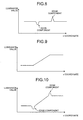
- Fig. 8 is a graph for explaining an example of results of edge extraction using the edge extraction filter. As depicted in Fig. 8, edge components (edge information) are extracted from the image information.
- the filter determining unit 104 specifies, from the noise-removal-filter size database 140, the size of the filter corresponding to the imaging condition obtained by the imaging-condition obtaining unit 103 (step S608). Specifically, the size of the luminance filter and the size of the color filter corresponding to the sensitivity of camera, exposure time, and temperature at shooting, which are imaging conditions, are specified.
- the filter determining unit 104 specifies, from the Gaussian ⁇ -value database 150, a s value of the Gaussian function corresponding to the imaging condition obtained by the imaging-condition obtaining unit 103 (step S609).
- the filter determining unit 104 determines a luminance filter from the filter size of the luminance filter and the specified ⁇ value of the Gaussian function, and determines a color filter from the filter size of the color filter and the specified ⁇ value of the Gaussian function (step S610).
- the luminance-component noise removing unit 105 uses the luminance filter determined by the filter determining unit 104 to remove noise from the luminance information (step S611).
- Fig. 9 is a graph for explaining results of noise removal using the luminance filter.
- the color-component noise removing unit 106 uses the color filter determined by the filter determining unit 104 to remove noise from the color information (step S612).
- the image-information synthesizing unit 107 combines the edge information, and the luminance information and the color information with noise removed therefrom to generate image information in YUV format (step S613).
- Fig. 10 is a graph for explaining results obtained by combining edge information and luminance information with noise removed therefrom. In the synthesized image information, since edges are clearly represented as depicted in Fig. 10, an image without edge blurring and with noise removed therefrom is obtained.
- the image-information compressing unit 108 compresses the image information in YUV format generated by the image-information synthesizing unit 107 to JPEG format (step S614).
- the image-information output unit 109 outputs the image information compressed by the image-information compressing unit 108 to a memory card or the like (step S615).
- the image information is separated into luminance information and color information; edge information is extracted from the luminance information; a noise removal process is performed on the luminance information and the color information, and image information is further synthesized from the edge information and the luminance information and color information with noise removed therefrom.
- edge components can be extracted in advance before noise removal, and then the edge components can be combined after noise removal.
- the edge can be smoothed at the time of noise removal to complement an image with image blurring. That is, noise can be effectively removed with edge blurring being suppressed to keep high image quality.
- a filter size, ⁇ value, and k value are specified based on the imaging condition and then the value of the filter is calculated in order to determine an edge extraction filter.
- the edge extraction filter may be determined directly from the imaging condition.
- a database storing imaging conditions and edge extraction filters in association with each other is provided, and an edge extraction filter corresponding to the imaging conditions is specified. Then, by using the specified edge extraction filter, edge information is extracted from the luminance information.
- FIG. 11 is a block diagram of a hardware configuration of a digital camera according to the first embodiment.
- a Charge Coupled Device CCD
- a mechanical shutter 2 is disposed between the imaging optical system 1 and the CCD 3. With the mechanical shutter 2, incident light to the CCD 3 can be intercepted.
- the imaging optical system 1 and the mechanical shutter 2 are driven by a motor driver 6.
- the CCD 3 converts an optical image formed on an imaging surface to an electric signal for output as analog image data.
- the image information output from the CCD 3 has noise components removed by a Correlated Double Sampling (CDS) circuit 4, is converted by an analog-to-digital (A/D) converter 5 to a digital value, and is then output to an image processing circuit 8.
- CDS Correlated Double Sampling
- A/D analog-to-digital
- the image processing circuit 8 uses a Synchronous Dynamic Random Access Memory (SDRAM) 12 that temporarily stores image data to perform various image processes, including YUV conversion, white balance control, contrast correction, edge enhancement, and color conversion.
- SDRAM Synchronous Dynamic Random Access Memory
- white balance control is an image process of adjusting color density of the image information
- contrast correction is an image process of adjusting contrast of the image information
- Edge enhancement is an image process of adjusting sharpness of the image information
- color conversion is an image process of adjusting shades of color of the image information.
- the image processing circuit 8 causes the image information subjected to signal processing and image processing to be displayed on a liquid-crystal display (LCD) 16.
- LCD liquid-crystal display
- the image information subjected to signal processing and image processing is recorded on a memory card 14 via a compression/decompression circuit 13.
- the compression/decompression circuit 13 compresses the image information output from the image processing circuit 8 upon an instruction obtained from an operating unit 15 and then outputs the result to the memory card 14. Also, the compression/decompression circuit 13 decompresses the image information read from the memory card 14 for output to the image processing circuit 8.
- the CCD 3, the CDS circuit 4, and the A/D converter 5 are timing-controlled by a Central Processing Unit (CPU) 9 via a timing signal generator 7 that generates a timing signal. Furthermore, the image processing circuit 8, the compression/decompression circuit 13, and the memory card 14 are also controlled by the CPU 9.
- CPU Central Processing Unit
- the CPU 9 performs various arithmetic operations according to a program(s), and has incorporated therein, for example, a Read Only Memory (ROM) 11, which is a read only memory having stored therein the program(s) and others, and a Random Access Memory (RAM) 10, which is a freely readable and writable memory having a work area and various data storage areas for use in the course of various processes.
- ROM Read Only Memory
- RAM Random Access Memory
- a system controller loads a highly-sensitive noise removal program from the ROM 11 to the RAM 10 for execution.
- the noise removal program obtains, via the system controller, settings of imaging sensitivity and a parameter representing exposure time at shooting. An optimal noise removal setting condition corresponding to these parameters is read from the ROM 11 for noise removal.
- the image to be processed is temporarily stored in the SDRAM 12, and the stored image is subjected to a noise removal process.
- the edge-extraction-filter size database 120, the parameter database 130, the noise-removal-filter size database 140, and the Gaussian ⁇ -value database 150 can be configured by any storage medium generally used, such as the ROM 11 of the digital camera 1000, a Hard Disk Drive (HDD), an optical disk, and a memory card.
- HDD Hard Disk Drive
- the image processing program to be executed on the digital camera according to the present embodiment may be stored on a computer connected to a network, such as the Internet, and may be downloaded via the network for provision. Also, the image processing program to be executed on the digital camera according to the present embodiment may be provided or distributed via the network, such as the Internet.
- the image processing program according to the present embodiment may be incorporated in advance in the ROM or the like for provision.
- the image processing program to be executed on the digital camera according to the present embodiment is recorded in an installable or an executable format on a computer-readable storage medium, such as a Compact-Disk Read-Only Memory (CD-ROM.), Flexible Disk (FD), Compact-Disk Recordable (CD-R), or Digital Versatile Disk (DVD), for provision.
- a computer-readable storage medium such as a Compact-Disk Read-Only Memory (CD-ROM.), Flexible Disk (FD), Compact-Disk Recordable (CD-R), or Digital Versatile Disk (DVD), for provision.
- the image processing program to be executed on the digital camera according to the present embodiment has a module structure including each of the components (the image-information obtaining unit, the component separating unit, the imaging-condition obtaining unit, the filter determining unit, the luminance-component edge extracting unit, the luminance-component noise removing unit, the color-component noise removing unit, the image-information synthesizing unit, the image-information compressing unit, the image-information output unit, and others).
- each of the units that is, the image-information obtaining unit, the component separating unit, the imaging-condition obtaining unit, the filter determining unit, the luminance-component edge extracting unit, the luminance-component noise removing unit, the color-component noise removing unit, the image-information synthesizing unit, the image-information compressing unit, the image-information output unit, and others, is loaded and generated onto a main storage device.
- a second embodiment of the present invention is explained below.
- a digital camera as an example of an image processing device according to the second embodiment performs scaling on the luminance information and the color information with noise removed therefrom, and the scaled luminance information and color information, and the edge information are combined to generate image information.
- the scaled luminance information and color information, and the edge information are combined to generate image information.
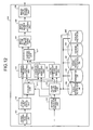
- FIG. 12 is a block diagram of the configuration of an image processing unit 200 according to the second embodiment.
- the image processing unit 200 includes the image-information obtaining unit 101, the component separating unit 102, the imaging-condition obtaining unit 103, the filter determining unit 104, a scaling unit 211, the luminance-component edge extracting unit 110, the luminance-component noise removing unit 105, the color-component noise removing unit 106, an inverse scaling unit 212, the image-information synthesizing unit 107, the image-information compressing unit 108, the image-information output unit 109, the edge-extraction-filter size database 120, the parameter database 130, the noise-removal-filter size database 140, the Gaussian ⁇ -value database 150, and a scaling factor database 260.
- the configuration and function of the image-information obtaining unit 101, the component separating unit 102, the imaging-condition obtaining unit 103, the filter determining unit 104, the luminance-component edge extracting unit 110, the luminance-component noise removing unit 105, the color-component noise removing unit 106, the image-information synthesizing unit 107, the image-information compressing unit 108, the image-information output unit 109, the edge-extraction-filter size database 120, the parameter database 130, the noise-removal-filter size database 140, and the Gaussian ⁇ -value database 150 are similar to those in the first embodiment, and are not explained herein.
- the scaling factor database 260 stores a scaling factor for each of the luminance information and the color information for scaling corresponding to the imaging condition.
- Fig. 13 is a table for explaining an example of a data structure of the scaling-factor database.
- the scaling factor database 260 stores imaging conditions and scaling factors for the luminance information and the color information in association with each other.
- the scaling factor is a ratio of changing the size of the luminance information or the color information. To reduce the size, the scaling factor is set smaller than 100%. When scaling is performed at a scaling factor smaller than 100%, the image after scaling is smaller than the original image. When filtering is performed on the image subjected to reduced scaling, since the image subjected to reduced scaling is smaller than the original image, the process time can be reduced, thereby speeding-up the process. Also, by reducing the original image, an effect of a low-pass filter can be obtained.
- the scaling factor is three time in width and three time in length and the size of the noise removal filter is 5x5
- the effect of a noise removal filter of 15 ⁇ 15 size can be obtained.
- a 15 ⁇ 15 noise removal filter process is performed on the image information, a large amount of time is required.
- similar process is achieved through a 3x3 scaling process and a noise removal process using a 5 ⁇ 5 noise removal filter, the process time can be reduced.
- the scaling unit 211 uses a scaling factor corresponding to the imaging condition obtained from the scaling factor database 260 to perform scaling on the luminance information and the color information obtained through separation by the component separating unit 102.
- the inverse scaling unit 212 uses an inverse scaling factor of the scaling unit 211 to perform scaling on the luminance information with noise removed therefrom by the luminance-component noise removing unit 105 and the color information with noise removed therefrom by the color-component noise removing unit 106.
- FIGs. 14A and 14B are flowcharts of the image processing procedure performed by the image-information obtaining unit, the component separating unit, the imaging-condition obtaining unit, the filter determining unit, the scaling unit, the luminance-component edge extracting unit, the luminance-component noise removing unit, the color-component noise removing unit, the inverse scaling unit, the image-information synthesizing unit, the image-information compressing unit, and the image-information output unit.
- the image processing procedure according to the second embodiment has common portions with that of the flowchart depicted in Figs. 6A and 6B, and therefore only different portions are explained herein.
- steps S1401 to S1410 the explanation in Figs. 6A and 6B is referred to, and these steps are not explained herein.
- the scaling unit 211 specifies a scaling factor corresponding to the imaging condition from the scaling factor database 260 (step S1411). A scaling factor is specified for each of the luminance information and the color information. The scaling unit 211 then performs scaling on the luminance information and the color information obtained through separation by the component separating unit 102 with respective scaling factors (step S1412).
- the luminance-component noise removing unit 105 uses the luminance filter to remove noise from the luminance information subjected to scaling by the scaling unit 211 (step S1413).
- the color-component noise removing unit 106 uses the color filter to remove noise from the color information subjected to scaling by the scaling unit 211 (step S1414).
- the inverse scaling unit 212 performs scaling on the luminance information with noise removed therefrom by the luminance-component noise removing unit 105 and the color information with noise removed therefrom by the color-component noise removing unit 106 each at an inverse scaling factor (step S1415).
- the image-information synthesizing unit 107 combines the edge information, and the luminance information and color information subjected to scaling to form image information in YUV format (step S1416).
- the image-information compressing unit 108 compresses the image information in YUV format generated by the image-information synthesizing unit 107 to JPEG format (step S1417).
- the image-information output unit 109 outputs the image information compressed by the image-information compressing unit 108 to a memory card or the like (step S1418).
- a third embodiment of the present invention is explained below.
- edge extraction and noise removal of image information are performed in the image processing apparatus in place of an imaging device.
- only different portions from those according to the first embodiment are explained.
- FIG. 15 is a block diagram of the configuration of an image processing apparatus 300 according to the third embodiment.
- the image processing apparatus 300 includes an image-information obtaining unit 301, an image-information converting unit 313, the component separating unit 102, an imaging-condition obtaining unit 303, the filter determining unit 104, the luminance-component edge extracting unit 110, the luminance-component noise removing unit 105, the color-component noise removing unit 106, the image-information synthesizing unit 107, an image-information converting unit 314, an image-information output unit 309, the edge-extraction-filter size database 120, the parameter database 130, the noise-removal-filter size database 140, and the Gaussian ⁇ -value database 150.
- the configuration and function of the component separating unit 102, the filter determining unit 104, the luminance-component edge extracting unit 110, the luminance-component noise removing unit 105, the color-component noise removing unit 106, the image-information synthesizing unit 107, the edge-extraction-filter size database 120, the parameter database 130, the noise-removal-filter size database 140, and the Gaussian ⁇ -value database 150 are similar to those in the first embodiment, and are not explained herein.
- the image-information obtaining unit obtains image information stored in a storage medium or image information transmitted via a network.
- the image-information converting unit 313 converts the image information obtained by the image-information obtaining unit 301 to image information in YUV format.
- the imaging-condition obtaining unit 303 obtains an imaging condition from the image information obtained by the image-information obtaining unit 301.
- the image-information converting unit 314 converts the image information in YUV format generated by the image-information synthesizing unit 107 to image information in another format.
- the image-information output unit 309 outputs the image information converted by the image-information converting unit 314 to an HDD or printer.
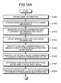
- FIGs. 16A and 16B depict a flowchart of an image processing procedure performed by the image-information obtaining unit, the image-information converting unit, the component separating unit, the imaging-condition obtaining unit, the filter determining unit, the luminance-component edge extracting unit, the luminance-component noise removing unit, the color-component noise removing unit, the image-information synthesizing unit, the image-information converting unit, and the image-information output unit.
- the image processing procedure according to the present embodiment is approximately similar to that of the flowchart depicted in Figs. 6A and 6B, and therefore only different portions are explained herein.
- steps S1605 to S1614 the explanation in Figs. 6A and 6B is referred to, and these steps are not explained herein.
- the image-information obtaining unit 301 obtains image information stored in a storage medium or image information transmitted through a network (step S1601).
- the image-information converting unit 313 converts the image information obtained by the image-information obtaining unit 301 to image information in YUV format (step S1602). For example, when the obtained image information is in RGB format, such image information is converted by the following conversion equation to image information in YUV format.
- [ Y U V ] 0.299 0.587 0.114 0.5 - 0.419 - 0.081 - 0.169 - 0.332 0.5 R G B
- the component separating unit 102 separates the converted image information in YUV format into luminance information and color information (step S1603).
- the imaging-condition obtaining unit 303 obtains an imaging condition(s) from the image information obtained by the image-information obtaining unit 301 (step S1604). For example, when the image information is in Exchangeable Image File Format (Exif), the image information additionally has recorded therein data of the imaging device, such as the manufacturer, model number, imaging sensitivity, and exposure time at shooting of the imaging device.
- the image-information converting unit 314 converts the image information in YUV format generated by the image-information synthesizing unit 107 to, for example, image information in RGB format (step S1615).
- image information in YUV format is converted to image information in RGB format
- the following conversion equation is used for conversion.
- [ R G B ] 1.0 1.402 0 1.0 - 0.174 - 0.344 1.0 0 1.772 Y U V
- the image-information output unit 309 outputs the image information obtained through conversion by the image-information converting unit 314 to a storage medium or printer (step S1616).
- the image information in YUV format is separated into luminance information and color information; edge information is extracted from the luminance information; noise is removed from the luminance information and color information; and the edge information, the luminance information, and the color information are combined.
- noise can be effectively removed with edge blurring being suppressed too keep high image quality.
- noise is removed by using a filter suitable for each of the luminance information and the color information obtained through separation. With this, effective noise removal can be performed in consideration of the property of human eyes.
- the scaling process explained in the second embodiment may be incorporated in the present embodiment.
- the size of noise is increased due to an increase in imaging sensitivity and therefore the size of the noise removal filter has to be increased, scaling is performed on the luminance information and the color information for a noise removal process, and then scaling is performed at an inverse scaling factor after processing.
- the time required for the noise removal process can be reduced, thereby achieving an effective noise removal process at high speed.
- Fig. 17 is a block diagram of a hardware configuration of the image processing apparatus according to the third embodiment.
- the image processing apparatus 300 includes a CPU 24 that centrally controls each component.
- the CPU 24 has connected via a bus thereto a ROM 22 having stored therein a Basic Input Output System (BIOS) and others and a RAM 21 that rewritably stores various data and functions as a work area for the CPU, thereby forming a microcomputer.
- the bus has connected thereto an HDD 25 having stored therein a control program, a CD-ROM drive 26 that reads a CD-ROM 28, and an interface (I/F) 23, which is an interface for communication with a printer unit or the like.
- BIOS Basic Input Output System
- I/F interface
- the CD-ROM 28 depicted in Fig. 17 has stored therein a predetermined control program.
- the CPU 24 reads at the CD-ROM drive 26 the control program stored in the CD-ROM 28, and then installs the program on the HDD 25. With this, various processes as explained above can be performed.
- a memory card 29 has stored therein image information and others, which is read by a memory-card driver 27.
- the program may be downloaded over a network, such as the Internet, and may be installed on the HDD 25.
- a storage device that has stored therein the program at a server on a transmitting side is also a storage medium according to the present invention.
- the program may operate on a predetermined Operating System (OS).
- OS Operating System
- a part of various processes which will be explained further below may be executed by the OS, or may be included in a predetermined application software, such as a word processor software, or as a part of a group of program files forming the OS or the like.
- the edge-extraction-filter size database 120, the parameter database 130, the noise-removal-filter size database 140, and the Gaussian ⁇ -value database 150 can be configured by any storage medium generally used, such as a HDD, an optical disk, and a memory card.
- the image processing program to be executed on the image processing apparatus according to the present embodiment may be stored on a computer connected to a network, such as the Internet, and may be downloaded via the network for provision. Also, the image processing program to be executed on the image processing apparatus according to the present embodiment may be provided or distributed via the network, such as the Internet.
- the image processing program according to the present embodiment may be incorporated in advance in the ROM or the like for provision.
- the image processing program to be executed on the image processing apparatus is recorded in an installable or an executable format on a computer-readable storage medium, such as a CD-ROM, FD, CD-R, or DVD, for provision.
- a computer-readable storage medium such as a CD-ROM, FD, CD-R, or DVD
- the image processing program to be executed on the image processing apparatus has a module structure including each of the components (the image-information obtaining unit, the image-information converting unit, the component separating unit, the imaging-condition obtaining unit, the filter determining unit, the luminance-component edge extracting unit, the luminance-component noise removing unit, the color-component noise removing unit, the image-information synthesizing unit, the image-information output unit, and others).
- each of the units that is, the image-information obtaining unit, the image-information converting unit, the component separating unit, the imaging-condition obtaining unit, the filter determining unit, the luminance-component edge extracting unit, the luminance-component noise removing unit, the color-component noise removing unit, the image-information synthesizing unit, the image-information output unit, and others, is loaded and generated onto a main storage device.
- FIG. 18 is a block diagram of an image processing unit 400 according to the fourth embodiment.
- the image processing unit 400 includes the image-information obtaining unit 101, a highly-sensitive low-resolution image generating unit 415, a component separating unit 402, a color-component noise removing unit 406, a luminance-component noise removing unit 405, a luminance-component edge extracting unit 410, a scaling unit 411, a luminance-component synthesizing unit 416, an image-information synthesizing unit 407, and the image-information output unit 109.
- the configuration and function of the image-information obtaining unit 101 and the image-information output unit 109 are similar to those according to the first embodiment, and therefore not explained herein.
- the highly-sensitive low-resolution image generating unit 415 adds pixel values of a plurality of adjacent pixels in the image information obtained by the image-information obtaining unit 101 to calculate one pixel value, thereby generating highly-sensitive low-resolution image information from the obtained image information. For example, when four adjacent pixel values are added, the number of pixels becomes one quarter. However, the amount of light per pixel becomes four fold, and therefore the sensitivity becomes four fold.
- the number of pixels for adding their pixel values is not restricted to four.
- the shape formed by the pixels for adding their pixel values is not restricted to a square, but may be any one of various polygons, a straight line, or a polygonal line.
- the component separating unit 402 separates the highly-sensitive low-resolution image information generated by the highly-sensitive low-resolution image generating unit 415 into luminance information and color information. Also, the component separating unit 402 separates the image information obtained by the image-information obtaining unit 101 into luminance information and color information.
- the image information obtained by the image-information obtaining unit 101 is low-sensitive high-resolution image information with respect to the highly-sensitive low-resolution image information generated by adding the pixel values.
- the color-component noise removing unit 406 uses a filter stored in the apparatus to remove noise from the color information.
- a filter in addition to the filter stored in the apparatus, as explained in the first embodiment, a Gaussian smoothing filter may be calculated from the ⁇ value corresponding to the imaging condition, and the calculated filter may be used to remove noise from the color information.
- the luminance-component noise removing unit 405 uses a filter stored in the apparatus to remove noise from the luminance information.
- a filter in addition to the filter stored in the apparatus, as explained in the first embodiment, a Gaussian smoothing filter may be calculated from the ⁇ value corresponding to the imaging condition, and the calculated filter may be used to remove noise from the luminance information.
- the luminance-component edge extracting unit 410 uses a filter stored in the apparatus to extract edge information from the luminance information.
- a filter in addition to the filter stored in the apparatus, as explained in the first embodiment, a Laplacian of Gaussian (LoG) filter may be calculated from the ⁇ value and k value corresponding to the imaging condition, and the calculated filter may be used to extract edge information.
- LiG Laplacian of Gaussian
- the scaling unit 411 performs scaling on the color information with noise removed therefrom by the color-component noise removing unit 406, and also performs scaling on the luminance information obtained through separation by the component separating unit 402.
- the highly-sensitive low-resolution image generating unit 415 adds four pixel values to calculate one pixel value to generate highly-sensitive low-resolution image information, and when the image size becomes one quarter, each of the pixel values is scaled up four times so that the image has the original image size.
- the luminance-component synthesizing unit 416 synthesizes luminance information from the luminance information subjected to scaling by the scaling unit 411, the luminance information with noise removed therefrom by the luminance-component noise removing unit 405, and the edge information extracted from the luminance-component edge extracting unit 410.
- the image-information synthesizing unit 407 synthesizes image information from the color information subjected to scaling by the scaling unit 411 and the luminance information synthesized by the luminance-component synthesizing unit 416.
- FIG. 19 is a flowchart of an image processing procedure performed by the image-information obtaining unit, the highly-sensitive low-resolution image generating unit, the component separating unit, the color-component noise removing unit, the luminance-component noise removing unit, the luminance-component edge extracting unit, the scaling unit, the luminance-component synthesizing unit, the image-information synthesizing unit, and the image-information output unit.
- the image-information obtaining unit 101 obtains image information from temporary-storage memory (step S1901).
- the highly-sensitive low-resolution image generating unit 415 adds adjacent pixel values in the image information to generate highly-sensitive low-resolution image information (step S1902). With this, the number of pixel values is reduced, but the amount of exposure per pixel is increased.
- the component separating unit 402 separates the highly-sensitive low-resolution image information into color information (CrCb signal) and luminance information (Y signal) (step S1903).
- the color-component noise removing unit 406 removes noise from the color information obtained through separation (step S1904).
- a low-pass filter for example, a smoothing filer
- Fig. 20 is a drawing for explaining an example of a smoothing filter with a filter size of 3x3.
- the scaling unit 411 performs scaling on the color information with noise removed therefrom to the original image size (step S1905).
- the scaling unit 411 performs scaling on the luminance information obtained through separation to the original image size (step S1906).
- the luminance information obtained through separation from the highly-sensitive low-resolution image information generated by adding pixel values and the color information obtained through separation from the highly-sensitive low-resolution image information and further with noise removed therefrom have an image size before adding the pixel values.
- the component separating unit 402 separates the image information obtained by the image-information obtaining unit 101 into the luminance information (Y signal) and the color signal (CrCb signal) (step S1907).
- the luminance-component noise removing unit 405 removes noise from the luminance information obtained through separation (step S1908).
- a low-pass filter for example, the smoothing filter depicted in Fig. 20 is used.
- the luminance-component edge extracting unit 410 extracts edge information from the luminance information obtained through separation (step S1909).
- a LoG filter is used as an edge extraction filter.
- the filter can be calculated by using the equation (1) mentioned above.
- Fig. 21 is a drawing for explaining an example of an edge extraction filter with a filter size of 5 ⁇ 5.
- the equation (3) mentioned above is used.
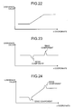
- Fig. 22 is a graph for explaining separated luminance information.
- Fig. 23 is a graph for explaining the results obtained by extracting an edge from the luminance information. In this manner, when edges are extracted from the luminance information as depicted in Fig. 22 by using the edge extraction filter as depicted in Fig. 21, edge components as depicted in Fig. 23 are extracted.
- the luminance-component synthesizing unit 416 synthesizes luminance information from the luminance information obtained through separation from the highly-sensitive low-resolution image information and subjected to scaling, the luminance information with noise removed therefrom, and the edge information (step S1910).
- Fig. 24 is a graph for explaining the results obtained by combining the luminance information and the edge information. Edge components are extracted as depicted in Fig. 24, and are combined with the luminance information obtained through separation from the highly-sensitive low-resolution image information and subjected to scaling and the luminance information with noise removed therefrom. With this, an image with high quality can be obtained without decreasing resolution of the image.
- the image-information synthesizing unit 407 synthesizes image information from the color information obtained through separation from the highly-sensitive low-resolution image information and subjected to scaling and the synthesized luminance information (step S1911).
- the image-information output unit 109 outputs the synthesized image information (step S1912).
- the processes at steps S1907 to S1909 and the processes at steps S1902 to S1906 may be concurrently performed.
- image information is synthesized from the luminance information from the highly-sensitive low-resolution image information, the color information with noise removed therefrom, the luminance information from the highly-sensitive low-resolution image information with noise removed therefrom, and the edge information.
- noise can be removed even when exposure time is short at the time of imaging, thereby obtaining image information with excellent color reproducibility and white balance and also with an excellent balance between color and luminance of the image.
- the luminance information separated from the highly-sensitive low-resolution image information is subjected to scaling and is combined to the image information, thereby suppressing noise of the synthesized image. That is, if the luminance value of the image information is used as it is, since the luminance value of the image information is low, the luminance value of the image information has to be amplified to be increased. With this, noise is also enhanced.
- the luminance information of the highly-sensitive low-resolution image is combined, the scaling factor of the amplification on the image information can be reduced. Therefore, the magnification factor of the noise is reduced, and noise components of the synthesized image are reduced. As a result, noise of the synthesized image can be reduced.
- an image is shot by the imaging unit, and by using one piece of image information stored in temporary-storage memory, highly-sensitive low-resolution image information and low-sensitive high-resolution image information are generated.
- highly-sensitive low-resolution image information and low-sensitive high-resolution image information may be generated by using two pieces of image information obtained by shooting an image twice by the imaging unit. At this time, two pieces of image information may be generated with the same exposure time.
- two pieces of image information may be generated with different exposure times, and image information with a long exposure time may be used to generate highly-sensitive low-resolution image information, and image information with a short exposure time may be used to generate low-sensitive high-resolution image information.
- a hardware configuration of a digital camera which is one example of an imaging device that performs the image process.
- the hardware configuration of the digital camera is approximately similar to that in Fig. 11. Therefore, Fig. 11 and its explanation are referred to, and only different portions are explained herein.
- the CCD 3 converts an optical image formed on an imaging surface to an electric signal for output as analog image information.
- image information shot once is used to generate highly-sensitive low-resolution image information and low-sensitive high-resolution image information.
- image information may be sequentially output through two exposures, and the output image information may be used. In this case, a process of adding pixel values to one piece of image information exposed.
- the image information output from the CCD 3 has noise components removed by the CDS circuit 4, is converted by the A/D converter 5 to a digital value, and is then output to the image processing circuit 8.
- noise removal is performed by a circuit, and is different from noise removal through image processing.
- the image processing circuit 8 uses the SDRAM 12 that temporarily stores image information to perform various image processes, including YCrCb conversion, white balance control, contrast correction, edge enhancement, and color conversion.
- white balance control is an image process of adjusting color density of the image information
- contrast correction is an image process of adjusting contrast of the image information.
- Edge enhancement is an image process of adjusting sharpness of the image information
- color conversion is an image process of adjusting shades of color of the image information.
- the image processing circuit 8 causes the image information subjected to signal processing and image processing to be displayed on the LCD 16.
- a system controller loads an image processing program from the ROM 11 to the RAM 10 for execution.
- the image processing program accesses the YCrCb image temporarily stored in the SDRAM to obtain, via the system controller, parameters and filters for color-component noise removal, luminance-component noise removal, and luminance-component edge extraction for performing these processes.
- the image processing program to be executed on the digital camera according to the present embodiment has a module structure including each of the components (the image-information obtaining unit, the highly-sensitive low-resolution image generating unit, the component separating unit, the color-component noise removing unit, the scaling unit, the luminance-component edge extracting unit, the luminance-component noise removing unit, the luminance-component synthesizing unit, the image-information synthesizing unit, the image-information output unit, and others).
- each of the units that is, the image-information obtaining unit, the highly-sensitive low-resolution image generating unit, the component separating unit, the color-component noise removing unit, the scaling unit, the luminance-component edge extracting unit, the luminance-component noise removing unit, the luminance-component synthesizing unit, the image-information synthesizing unit, the image-information output unit, and others, is loaded and generated onto a main storage device.
- Fig. 25 is a block diagram of the configuration of an image processing apparatus 500 according to the fifth embodiment.
- the image processing apparatus 500 includes an image-information obtaining unit 501, a component converting unit 517, the component separating unit 402, the color-component noise removing unit 406, the scaling unit 411, the luminance-component noise removing unit 405, the luminance-component edge extracting unit 410, the luminance-component synthesizing unit 416, the image-information synthesizing unit 407, a component converting unit 518, the imaging-condition obtaining unit 303, and the image-information output unit 309.
- the configuration and function of the component separating unit 402, the color-component noise removing unit 406, the scaling unit 411, the luminance-component noise removing unit 405, the luminance-component edge extracting unit 410, the luminance-component synthesizing unit 416, and the image-information synthesizing unit 407 are similar to those in the fourth embodiment.
- the configuration and function of the imaging-condition obtaining unit 303 and the image-information output unit 309 are similar to those in the third embodiment. Therefore, these components are not explained herein.
- the image-information obtaining unit 501 obtains highly-sensitive low-resolution image information and low-sensitive high-resolution image information stored in memory.
- the highly-sensitive low-resolution image information is generated in a manner similar to that of the fourth embodiment by adding pixel values of a plurality of pixels of the image information shot by the imaging unit.
- an imaging condition(s) such as the number of pixels for adding their pixel values at shooting, is added to the highly-sensitive low-resolution image information generated by performing a pixel-value addition process at shooting.
- the highly-sensitive low-resolution image information is stored in a memory card of a digital camera.
- the shot image information (low-sensitive high-resolution image information) is stored with the imaging condition added thereto.
- the imaging condition added to the image information includes the manufacturer, model number, imaging sensitivity, and the number of pixels for adding their pixel values at shooting of the imaging device.
- the image size of the highly-sensitive low-resolution image information is reduced due to addition of pixel values, and the image size of the low-sensitive high-resolution image is a normal size.
- the component converting unit 517 converts image information in RGB format to image information in YCrCb format.
- the component converting unit 518 converts image information in YCrCb format to image information in RGB format.
- Fig. 26 is a flowchart of an image processing procedure performed by the image-information obtaining unit, the component converting unit, the component separating unit, the color-component noise removing unit, the scaling unit, the luminance-component noise removing unit, the luminance-component edge extracting unit, the luminance-component synthesizing unit, the image-information synthesizing unit, and the image-information output unit.
- the image-information obtaining unit 501 obtains the highly-sensitive low-resolution image information in RGB format from memory (step S2601). Since the highly-sensitive low-resolution image information includes the imaging condition(s), the number of pixels for adding their pixel values at shooting is also obtained, for example.
- the component converting unit 517 converts the image information in RGB format to image information in YCrCb format (step S2602).
- the component separating unit 402 separates the highly-sensitive low-resolution image information into color information (CrCb signal) and luminance information (Y signal) (step S2603).
- the color-component noise removing unit 406 removes noise from the color information obtained through separation (step S2604).
- the scaling unit 411 uses the number of pixels for adding their pixel values obtained as an imaging condition to perform scaling on the color information with noise removed therefrom to the original size (step S2605). Also, the scaling unit 411 uses the number of pixels for adding their pixel values obtained as an imaging condition to perform scaling on the luminance information obtained through separation to the original size (step S2606). With this, the luminance information obtained through separation from the highly-sensitive low-resolution image information generated by adding the pixel values and the color information with noise removed therefrom have the original image size before adding the pixel values.
- the image-information obtaining unit 501 obtains the low-sensitive high-resolution image information in RGB format from memory (step S2607). Since the low-sensitive high-resolution image information includes the imaging condition(s), the imaging condition is also obtained.
- the component converting unit 517 converts the image information in RGB format to image information in YCrCb format (step S2608). For steps S2609 to S2612, the explanation of Fig. 19 is referred to.
- the image-information synthesizing unit 407 synthesizes image information from the color information obtained through separation and subjected to scaling and the synthesized luminance information (step S2613).
- the component converting unit 518 converts the image information in YCrCb format to image information in RGB format (step S2614).
- the image-information output unit 309 outputs the image information obtained through conversion to a storage medium or printer (step S2615).
- the processes at steps S2607 to S2611 may be performed concurrently with the processes at steps S2601 to S2606.
- image information is synthesized from the luminance information from the highly-sensitive low-resolution image information, the color information with noise removed therefrom, the luminance information from the highly-sensitive low-resolution image information with noise removed therefrom, and the edge information.
- noise can be removed even when exposure time is short at the time of imaging, thereby obtaining image information with excellent color reproducibility and white balance and also image with an excellent balance between color and luminance of the image.
- the process is explained starting from adding pixel values at shooting to generate highly-sensitive low-resolution image information and obtaining the highly-sensitive low-resolution image information and the low-sensitive high-resolution image information stored in memory.
- one shot piece of image information may be stored in memory, and the process of adding pixel values may be performed as image processing to generate highly-sensitive low-resolution image information.
- two pieces of image information may be shot by the imaging unit, the process of adding pixel values may be performed on one of these pieces of image information, and then the image processing explained above may be performed.
- the previously-extracted edge information is combined to generate image information. Therefore, an effect can be achieved such that an image with high quality and less edge blurring can be obtained.
- the edge information is extracted by a general filtering process. Therefore, an effect can be achieved such that an edge extraction process can be easily performed.
- an effect can be achieved such that an image with high quality and less edge blurring can be obtained.
- the edge information is extracted by a filter found based on the ⁇ value and k value corresponding to the imaging condition. Therefore, an effect can be achieved such that an image with high quality and less edge blurring can be obtained.
- the edge information is extracted by a filter corresponding to the imaging condition. Therefore, an effect can be achieved such that an image with high quality and less edge blurring can be obtained.
- edge extraction suited for the image quality level can be performed. Therefore, an effect can be achieved such that an image with high quality and less edge blurring can be obtained.
- edge extraction suited for the image quality level can be performed. Therefore, an effect can be achieved such that an image with high quality and less edge blurring can be obtained.
- edge extraction suited for the image quality level can be performed. Therefore, an effect can be achieved such that an image with high quality and less edge blurring can be obtained.
- a noise removal process is performed after scaling up or down the luminance information and the color information. Therefore, an effect can be achieved such that the time for the noise removal process can be reduced.
- the sensitivity of the image information is increased. Therefore, an effect can be achieved such that a high-quality image with excellent color reproducibility and white balance can be obtained.
- noise is removed from the highly-sensitive low-resolution color information. Therefore, an effect can be achieved such that an image with high quality and less edge blurring can be obtained.
- the previously-extracted edge information is combined to generate image information. Therefore, an effect can be achieved such that an image with high quality and less edge blurring can be obtained.
- the sensitivity of the image information imaged can be improved. Therefore, an effect can be achieved such that a high-quality image with excellent color reproducibility and white balance can be obtained.
- the previously-extracted edge information is combined to generate image information. Therefore, an effect can be achieved such that an image with high quality and less edge blurring can be obtained.
- the previously-extracted edge information is combined to generate image information. Therefore, an effect can be achieved such that an image with high quality and less edge blurring can be obtained. Also, a noise removal process is performed after scaling up or down the luminance information and the color information. Therefore, an effect can be achieved such that the time for the noise removal process can be reduced.
- the sensitivity of the image information can be improved. Therefore, an effect can be achieved such that a high-quality image with excellent color reproducibility and white balance can be obtained.
- the previously-extracted edge information is combined to generate image information. Therefore, an effect can be achieved such that an image with high quality and less edge blurring can be obtained.
- a noise removal process is performed after scaling up or down the luminance information and the color information. Therefore, an effect can be achieved such that the time for the noise removal process can be reduced.
- the sensitivity of the image information can be improved. Therefore, an effect can be achieved such that a high-quality image with excellent color reproducibility and white balance can be obtained.
Applications Claiming Priority (2)
| Application Number | Priority Date | Filing Date | Title |
|---|---|---|---|
| JP2006208063 | 2006-07-31 | ||
| JP2007034532A JP5009004B2 (ja) | 2006-07-31 | 2007-02-15 | 画像処理装置、撮像装置、画像処理方法、および画像処理プログラム |
Publications (3)
| Publication Number | Publication Date |
|---|---|
| EP1885136A2 true EP1885136A2 (fr) | 2008-02-06 |
| EP1885136A3 EP1885136A3 (fr) | 2009-12-09 |
| EP1885136B1 EP1885136B1 (fr) | 2013-05-22 |
Family
ID=38621246
Family Applications (1)
| Application Number | Title | Priority Date | Filing Date |
|---|---|---|---|
| EP07252794.8A Active EP1885136B1 (fr) | 2006-07-31 | 2007-07-12 | Appareil de traitement des images, appareil de photo, procédé de traitement des images, et produit de programme informatique |
Country Status (3)
| Country | Link |
|---|---|
| US (1) | US8351731B2 (fr) |
| EP (1) | EP1885136B1 (fr) |
| JP (1) | JP5009004B2 (fr) |
Families Citing this family (18)
| Publication number | Priority date | Publication date | Assignee | Title |
|---|---|---|---|---|
| JP4523008B2 (ja) * | 2007-01-10 | 2010-08-11 | 学校法人神奈川大学 | 画像処理装置および撮像装置 |
| JP2009110137A (ja) * | 2007-10-29 | 2009-05-21 | Ricoh Co Ltd | 画像処理装置、画像処理方法及び画像処理プログラム |
| US20090175535A1 (en) * | 2008-01-09 | 2009-07-09 | Lockheed Martin Corporation | Improved processing of multi-color images for detection and classification |
| US8254718B2 (en) * | 2008-05-15 | 2012-08-28 | Microsoft Corporation | Multi-channel edge-aware chrominance noise reduction |
| EP2124189A1 (fr) * | 2008-05-19 | 2009-11-25 | Mitsubishi Electric Information Technology Centre Europe B.V. | Traitement d'image pour améliorer la netteté des images |
| EP2124190B1 (fr) * | 2008-05-19 | 2011-08-31 | Mitsubishi Electric Information Technology Centre Europe B.V. | Traitement d'image pour améliorer la netteté des images |
| JP5223702B2 (ja) | 2008-07-29 | 2013-06-26 | 株式会社リコー | 画像処理装置、ノイズ低減方法、プログラム、記憶媒体 |
| JP5430379B2 (ja) * | 2009-02-03 | 2014-02-26 | キヤノン株式会社 | 撮像装置及びその制御方法及びプログラム |
| WO2011145296A1 (fr) * | 2010-05-21 | 2011-11-24 | パナソニック株式会社 | Appareil de saisie d'image, appareil de traitement d'image, procédé de traitement d'image et programme de traitement d'image |
| JP5882576B2 (ja) | 2010-12-01 | 2016-03-09 | キヤノン株式会社 | 画像処理装置及び画像処理装置の制御方法、並びにプログラム |
| CN103067661B (zh) * | 2013-01-07 | 2017-12-05 | 华为终端有限公司 | 图像处理方法、装置和拍摄终端 |
| JP6344638B2 (ja) | 2013-03-06 | 2018-06-20 | 株式会社リコー | 物体検出装置、移動体機器制御システム及び物体検出用プログラム |
| US9047665B2 (en) | 2013-08-21 | 2015-06-02 | Panasonic Intellectual Property Management Co., Ltd. | Image processing apparatus |
| JP6573354B2 (ja) * | 2014-11-28 | 2019-09-11 | キヤノン株式会社 | 画像処理装置、画像処理方法、及びプログラム |
| CN105163124B (zh) * | 2015-08-28 | 2019-01-18 | 京东方科技集团股份有限公司 | 一种图像编码方法、图像解码方法及装置 |
| US10880566B2 (en) | 2015-08-28 | 2020-12-29 | Boe Technology Group Co., Ltd. | Method and device for image encoding and image decoding |
| CN108550158B (zh) * | 2018-04-16 | 2021-12-17 | Tcl华星光电技术有限公司 | 图像边缘处理方法、电子装置及计算机可读存储介质 |
| CN109089046B (zh) * | 2018-09-25 | 2021-06-04 | Oppo广东移动通信有限公司 | 图像降噪方法、装置、计算机可读存储介质及电子设备 |
Citations (11)
| Publication number | Priority date | Publication date | Assignee | Title |
|---|---|---|---|---|
| EP0964584A1 (fr) * | 1993-12-22 | 1999-12-15 | Eastman Kodak Company | Caméra électronique prenant les couleurs de manière séquentielle |
| WO2000053093A1 (fr) * | 1999-03-10 | 2000-09-14 | Debex (Proprietary) Limited | Appareil de formation d'images |
| EP1176801A2 (fr) * | 2000-07-27 | 2002-01-30 | Noritsu Koki Co., Ltd. | Procédé, appareil et programme de traitement d'image et support d'enregistrement pour enregistrer le programme de traitement d'image |
| US20030174223A1 (en) * | 2002-03-15 | 2003-09-18 | Kenkichi Hayashi | Noise reducing apparatus |
| US20040036775A1 (en) * | 2002-08-21 | 2004-02-26 | Alpha Innotech Corporation | Method and apparatus for extending signal range |
| EP1411471A2 (fr) * | 2002-10-15 | 2004-04-21 | Eastman Kodak Company | Elimination d'artéfacts de crènelage dans des images numériques en couleur |
| US20040165080A1 (en) * | 2003-02-26 | 2004-08-26 | David Burks | Image sensor for capturing and filtering image data |
| EP1549049A2 (fr) * | 2003-11-28 | 2005-06-29 | Noritsu Koki Co., Ltd. | Procédé de réduction du bruit dans une image |
| US20050157189A1 (en) * | 2003-10-24 | 2005-07-21 | Olympus Corporation | Signal-processing system, signal-processing method, and signal-processing program |
| US20060066736A1 (en) * | 2004-09-28 | 2006-03-30 | Olympus Corporation | Image pickup system, noise reduction processing device and image pick-up processing program |
| EP1947840A1 (fr) * | 2005-10-26 | 2008-07-23 | Olympus Corporation | Systeme de traitement d'image et programme de traitement d'image |
Family Cites Families (13)
| Publication number | Priority date | Publication date | Assignee | Title |
|---|---|---|---|---|
| US6738510B2 (en) * | 2000-02-22 | 2004-05-18 | Olympus Optical Co., Ltd. | Image processing apparatus |
| JP2002358514A (ja) | 2000-12-14 | 2002-12-13 | Ricoh Co Ltd | 画像歪み補正装置、プログラム、記憶媒体、画像歪み補正方法、画像読取装置および画像形成装置 |
| JP2003219180A (ja) * | 2002-01-25 | 2003-07-31 | Canon Inc | 画像処理方法、画像処理装置、コンピュータ読み取り可能な記憶媒体及びコンピュータプログラム |
| JP2003274180A (ja) * | 2002-03-12 | 2003-09-26 | Canon Inc | 画像処理装置、画像処理方法、プリンタドライバ、コンピュータ読み取り可能な記憶媒体及びコンピュータプログラム |
| JP3762725B2 (ja) * | 2002-08-22 | 2006-04-05 | オリンパス株式会社 | 撮像システムおよび画像処理プログラム |
| JP4262504B2 (ja) | 2003-03-28 | 2009-05-13 | 富士フイルム株式会社 | 撮像装置および電荷検出装置 |
| JP2004318356A (ja) * | 2003-04-15 | 2004-11-11 | Olympus Corp | 画像処理装置、画像処理方法及びそのプログラム |
| JP2005006213A (ja) * | 2003-06-13 | 2005-01-06 | Canon Inc | 画像処理装置およびその方法 |
| JP2005044915A (ja) | 2003-07-25 | 2005-02-17 | Minolta Co Ltd | 撮像素子および撮像装置 |
| JP2005303519A (ja) * | 2004-04-08 | 2005-10-27 | Konica Minolta Photo Imaging Inc | 撮像装置 |
| JP2006014054A (ja) | 2004-06-28 | 2006-01-12 | Nec Access Technica Ltd | カメラ付携帯電子機器による接写防止方法及びカメラ付携帯電子機器 |
| JP4822773B2 (ja) * | 2004-09-13 | 2011-11-24 | キヤノン株式会社 | 色ノイズ低減回路及びそれを用いた撮像装置 |
| JP4961182B2 (ja) | 2005-10-18 | 2012-06-27 | 株式会社リコー | ノイズ除去装置、ノイズ除去方法、ノイズ除去プログラム及び記録媒体 |
-
2007
- 2007-02-15 JP JP2007034532A patent/JP5009004B2/ja active Active
- 2007-07-12 EP EP07252794.8A patent/EP1885136B1/fr active Active
- 2007-07-31 US US11/888,496 patent/US8351731B2/en active Active
Patent Citations (11)
| Publication number | Priority date | Publication date | Assignee | Title |
|---|---|---|---|---|
| EP0964584A1 (fr) * | 1993-12-22 | 1999-12-15 | Eastman Kodak Company | Caméra électronique prenant les couleurs de manière séquentielle |
| WO2000053093A1 (fr) * | 1999-03-10 | 2000-09-14 | Debex (Proprietary) Limited | Appareil de formation d'images |
| EP1176801A2 (fr) * | 2000-07-27 | 2002-01-30 | Noritsu Koki Co., Ltd. | Procédé, appareil et programme de traitement d'image et support d'enregistrement pour enregistrer le programme de traitement d'image |
| US20030174223A1 (en) * | 2002-03-15 | 2003-09-18 | Kenkichi Hayashi | Noise reducing apparatus |
| US20040036775A1 (en) * | 2002-08-21 | 2004-02-26 | Alpha Innotech Corporation | Method and apparatus for extending signal range |
| EP1411471A2 (fr) * | 2002-10-15 | 2004-04-21 | Eastman Kodak Company | Elimination d'artéfacts de crènelage dans des images numériques en couleur |
| US20040165080A1 (en) * | 2003-02-26 | 2004-08-26 | David Burks | Image sensor for capturing and filtering image data |
| US20050157189A1 (en) * | 2003-10-24 | 2005-07-21 | Olympus Corporation | Signal-processing system, signal-processing method, and signal-processing program |
| EP1549049A2 (fr) * | 2003-11-28 | 2005-06-29 | Noritsu Koki Co., Ltd. | Procédé de réduction du bruit dans une image |
| US20060066736A1 (en) * | 2004-09-28 | 2006-03-30 | Olympus Corporation | Image pickup system, noise reduction processing device and image pick-up processing program |
| EP1947840A1 (fr) * | 2005-10-26 | 2008-07-23 | Olympus Corporation | Systeme de traitement d'image et programme de traitement d'image |
Also Published As
| Publication number | Publication date |
|---|---|
| US20080027994A1 (en) | 2008-01-31 |
| US8351731B2 (en) | 2013-01-08 |
| EP1885136A3 (fr) | 2009-12-09 |
| EP1885136B1 (fr) | 2013-05-22 |
| JP5009004B2 (ja) | 2012-08-22 |
| JP2008061217A (ja) | 2008-03-13 |
Similar Documents
| Publication | Publication Date | Title |
|---|---|---|
| EP1885136B1 (fr) | Appareil de traitement des images, appareil de photo, procédé de traitement des images, et produit de programme informatique | |
| CN101119448A (zh) | 图像处理装置和方法,成像装置以及计算机程序产品 | |
| US8014627B2 (en) | Image processing apparatus, imaging apparatus, image processing method, and computer program product | |
| US7616240B2 (en) | Image processing method, image processing program, image processing apparatus, and digital still camera using the image processing apparatus | |
| EP1909487A1 (fr) | Appareil de captage d'images | |
| EP2399397B1 (fr) | Appareil de traitement d'image, appareil de prise d'image, procédé de traitement d'image et programme informatique | |
| JP4803178B2 (ja) | 画像処理装置、コンピュータプログラム製品および画像処理方法 | |
| EP2059027A1 (fr) | Dispositif de traitement d'images, caméra électronique et programme de traitement d'images | |
| JP5240194B2 (ja) | 信号処理方法および信号処理装置 | |
| EP1931134A1 (fr) | Dispositif d'imagerie | |
| JP2003141531A (ja) | ノイズリダクションシステム、ノイズリダクション方法、ノイズリダクションプログラム、及び電子カメラ | |
| WO2007077730A1 (fr) | Systeme d'imagerie et programme de traitement d'image | |
| EP3422690B1 (fr) | Appareil de traitement d'informations, procédé de commande associé et programme | |
| EP2214136B1 (fr) | Procédé et programme de contrôle d'appareil de capture d'images | |
| JP5589660B2 (ja) | 画像処理装置、撮像装置及び画像処理プログラム | |
| EP2148502B1 (fr) | Appareil et procédé de traitement d'images | |
| EP1887783B1 (fr) | Procede et appareil de traitement d'image | |
| JP2017229025A (ja) | 画像処理装置、画像処理方法、及びプログラム | |
| JP4687750B2 (ja) | デジタルカメラおよび画像信号処理用記憶媒体 | |
| JP2007164628A (ja) | 画像処理装置及び方法 | |
| JPH10290368A (ja) | 輪郭強調方法 | |
| JP2009122759A (ja) | 画像処理装置、画像処理方法およびプログラム | |
| JP2010218349A (ja) | 画像処理装置、直線近似方法および直線近似プログラム |
Legal Events
| Date | Code | Title | Description |
|---|---|---|---|
| PUAI | Public reference made under article 153(3) epc to a published international application that has entered the european phase |
Free format text: ORIGINAL CODE: 0009012 |
|
| AK | Designated contracting states |
Kind code of ref document: A2 Designated state(s): AT BE BG CH CY CZ DE DK EE ES FI FR GB GR HU IE IS IT LI LT LU LV MC MT NL PL PT RO SE SI SK TR |
|
| AX | Request for extension of the european patent |
Extension state: AL BA HR MK YU |
|
| PUAL | Search report despatched |
Free format text: ORIGINAL CODE: 0009013 |
|
| AK | Designated contracting states |
Kind code of ref document: A3 Designated state(s): AT BE BG CH CY CZ DE DK EE ES FI FR GB GR HU IE IS IT LI LT LU LV MC MT NL PL PT RO SE SI SK TR |
|
| AX | Request for extension of the european patent |
Extension state: AL BA HR MK RS |
|
| 17P | Request for examination filed |
Effective date: 20100428 |
|
| 17Q | First examination report despatched |
Effective date: 20100608 |
|
| AKX | Designation fees paid |
Designated state(s): DE ES FR GB IT NL |
|
| 17Q | First examination report despatched |
Effective date: 20120206 |
|
| GRAP | Despatch of communication of intention to grant a patent |
Free format text: ORIGINAL CODE: EPIDOSNIGR1 |
|
| GRAS | Grant fee paid |
Free format text: ORIGINAL CODE: EPIDOSNIGR3 |
|
| GRAA | (expected) grant |
Free format text: ORIGINAL CODE: 0009210 |
|
| AK | Designated contracting states |
Kind code of ref document: B1 Designated state(s): DE ES FR GB IT NL |
|
| REG | Reference to a national code |
Ref country code: GB Ref legal event code: FG4D |
|
| REG | Reference to a national code |
Ref country code: DE Ref legal event code: R096 Ref document number: 602007030570 Country of ref document: DE Effective date: 20130718 |
|
| PG25 | Lapsed in a contracting state [announced via postgrant information from national office to epo] |
Ref country code: ES Free format text: LAPSE BECAUSE OF FAILURE TO SUBMIT A TRANSLATION OF THE DESCRIPTION OR TO PAY THE FEE WITHIN THE PRESCRIBED TIME-LIMIT Effective date: 20130902 |
|
| REG | Reference to a national code |
Ref country code: NL Ref legal event code: VDEP Effective date: 20130522 |
|
| PG25 | Lapsed in a contracting state [announced via postgrant information from national office to epo] |
Ref country code: IT Free format text: LAPSE BECAUSE OF FAILURE TO SUBMIT A TRANSLATION OF THE DESCRIPTION OR TO PAY THE FEE WITHIN THE PRESCRIBED TIME-LIMIT Effective date: 20130522 Ref country code: NL Free format text: LAPSE BECAUSE OF FAILURE TO SUBMIT A TRANSLATION OF THE DESCRIPTION OR TO PAY THE FEE WITHIN THE PRESCRIBED TIME-LIMIT Effective date: 20130522 |
|
| PLBE | No opposition filed within time limit |
Free format text: ORIGINAL CODE: 0009261 |
|
| STAA | Information on the status of an ep patent application or granted ep patent |
Free format text: STATUS: NO OPPOSITION FILED WITHIN TIME LIMIT |
|
| 26N | No opposition filed |
Effective date: 20140225 |
|
| REG | Reference to a national code |
Ref country code: DE Ref legal event code: R097 Ref document number: 602007030570 Country of ref document: DE Effective date: 20140225 |
|
| REG | Reference to a national code |
Ref country code: FR Ref legal event code: PLFP Year of fee payment: 10 |
|
| REG | Reference to a national code |
Ref country code: FR Ref legal event code: PLFP Year of fee payment: 11 |
|
| REG | Reference to a national code |
Ref country code: FR Ref legal event code: PLFP Year of fee payment: 12 |
|
| PGFP | Annual fee paid to national office [announced via postgrant information from national office to epo] |
Ref country code: GB Payment date: 20220720 Year of fee payment: 16 Ref country code: DE Payment date: 20220620 Year of fee payment: 16 |
|
| PGFP | Annual fee paid to national office [announced via postgrant information from national office to epo] |
Ref country code: FR Payment date: 20220720 Year of fee payment: 16 |
|
| REG | Reference to a national code |
Ref country code: DE Ref legal event code: R119 Ref document number: 602007030570 Country of ref document: DE |
|
| GBPC | Gb: european patent ceased through non-payment of renewal fee |
Effective date: 20230712 |