EP1884187B1 - Endoskopische Einführhilfe und endoskopisches System - Google Patents
Endoskopische Einführhilfe und endoskopisches System Download PDFInfo
- Publication number
- EP1884187B1 EP1884187B1 EP07014085A EP07014085A EP1884187B1 EP 1884187 B1 EP1884187 B1 EP 1884187B1 EP 07014085 A EP07014085 A EP 07014085A EP 07014085 A EP07014085 A EP 07014085A EP 1884187 B1 EP1884187 B1 EP 1884187B1
- Authority
- EP
- European Patent Office
- Prior art keywords
- balloon
- balloons
- tube member
- disposed
- pipeline
- Prior art date
- Legal status (The legal status is an assumption and is not a legal conclusion. Google has not performed a legal analysis and makes no representation as to the accuracy of the status listed.)
- Expired - Fee Related
Links
Images


Classifications
-
- A—HUMAN NECESSITIES
- A61—MEDICAL OR VETERINARY SCIENCE; HYGIENE
- A61B—DIAGNOSIS; SURGERY; IDENTIFICATION
- A61B1/00—Instruments for performing medical examinations of the interior of cavities or tubes of the body by visual or photographical inspection, e.g. endoscopes; Illuminating arrangements therefor
- A61B1/00147—Holding or positioning arrangements
- A61B1/00154—Holding or positioning arrangements using guiding arrangements for insertion
-
- A—HUMAN NECESSITIES
- A61—MEDICAL OR VETERINARY SCIENCE; HYGIENE
- A61B—DIAGNOSIS; SURGERY; IDENTIFICATION
- A61B1/00—Instruments for performing medical examinations of the interior of cavities or tubes of the body by visual or photographical inspection, e.g. endoscopes; Illuminating arrangements therefor
- A61B1/00064—Constructional details of the endoscope body
- A61B1/00071—Insertion part of the endoscope body
- A61B1/0008—Insertion part of the endoscope body characterised by distal tip features
- A61B1/00082—Balloons
-
- A—HUMAN NECESSITIES
- A61—MEDICAL OR VETERINARY SCIENCE; HYGIENE
- A61B—DIAGNOSIS; SURGERY; IDENTIFICATION
- A61B1/00—Instruments for performing medical examinations of the interior of cavities or tubes of the body by visual or photographical inspection, e.g. endoscopes; Illuminating arrangements therefor
- A61B1/04—Instruments for performing medical examinations of the interior of cavities or tubes of the body by visual or photographical inspection, e.g. endoscopes; Illuminating arrangements therefor combined with photographic or television appliances
-
- A—HUMAN NECESSITIES
- A61—MEDICAL OR VETERINARY SCIENCE; HYGIENE
- A61B—DIAGNOSIS; SURGERY; IDENTIFICATION
- A61B17/00—Surgical instruments, devices or methods, e.g. tourniquets
- A61B17/22—Implements for squeezing-off ulcers or the like on the inside of inner organs of the body; Implements for scraping-out cavities of body organs, e.g. bones; Calculus removers; Calculus smashing apparatus; Apparatus for removing obstructions in blood vessels, not otherwise provided for
- A61B2017/22051—Implements for squeezing-off ulcers or the like on the inside of inner organs of the body; Implements for scraping-out cavities of body organs, e.g. bones; Calculus removers; Calculus smashing apparatus; Apparatus for removing obstructions in blood vessels, not otherwise provided for with an inflatable part, e.g. balloon, for positioning, blocking, or immobilisation
- A61B2017/22055—Implements for squeezing-off ulcers or the like on the inside of inner organs of the body; Implements for scraping-out cavities of body organs, e.g. bones; Calculus removers; Calculus smashing apparatus; Apparatus for removing obstructions in blood vessels, not otherwise provided for with an inflatable part, e.g. balloon, for positioning, blocking, or immobilisation with three or more balloons
-
- A—HUMAN NECESSITIES
- A61—MEDICAL OR VETERINARY SCIENCE; HYGIENE
- A61B—DIAGNOSIS; SURGERY; IDENTIFICATION
- A61B17/00—Surgical instruments, devices or methods, e.g. tourniquets
- A61B17/22—Implements for squeezing-off ulcers or the like on the inside of inner organs of the body; Implements for scraping-out cavities of body organs, e.g. bones; Calculus removers; Calculus smashing apparatus; Apparatus for removing obstructions in blood vessels, not otherwise provided for
- A61B2017/22051—Implements for squeezing-off ulcers or the like on the inside of inner organs of the body; Implements for scraping-out cavities of body organs, e.g. bones; Calculus removers; Calculus smashing apparatus; Apparatus for removing obstructions in blood vessels, not otherwise provided for with an inflatable part, e.g. balloon, for positioning, blocking, or immobilisation
- A61B2017/22065—Functions of balloons
- A61B2017/22069—Immobilising; Stabilising
Definitions
- This invention relates to an endoscopic insertion aid for facilitating insertion by aiding in the insertion of an insertion section of an endoscope into a region such as the large intestine where insertion is difficult, and an endoscopic system.
- an endoscopic insertion aid having a plurality of balloons at its distal end is disclosed in Jpn. Pat. Appln. KOKAI Publication No. 10-155733 .
- this endoscopic insertion aid the inner wall of a body cavity is expanded outward by the balloons to pull the aid to a hand side so that the aid is fixed to the inner wall of the body cavity.
- bent parts or twisted parts of the intestinal wall become substantially straight, thereby permitting the improvement of the insertability of an insertion section.
- WO 95/32011 discloses an instrument for insertion into a body cavity having three balloons (Fig. 17) wherein a balloon in the middle between a most distal balloon and a most proximal balloon has the smallest size.
- WO 03/080155 A1 discloses an endoscope comprising two balloons of the same diameter.
- the balloon provided on the distal side is formed to have an outside diameter smaller than or substantially equal to that on the proximal side.
- the balloon on the most proximal side alone is caught on the inner wall of the body cavity even if the aid is pulled to the hand side so that the balloons are fixed to the inner wall of the body cavity. Therefore, the balloons disclosed in Jpn. Pat. Appln. KOKAI Publication No. 10-155733 have weak force of fixing to the inner wall of the body cavity. This requires proficiency in the operation of pulling the aid to the hand side.
- This invention has been made to solve such a problem, and is directed to provide an endoscopic insertion aid and an endoscopic system capable of increasing the force of fixing balloons to the inner wall of a body cavity and to hook the intestinal wall with the balloons without causing a patient any pain.
- An endoscopic insertion aid in accordance with the present invention is described in claim 1 and endoscopic system using such an insertion aid is described in claim 6.
- the dependent claims describe preferred embodiments of the endoscopic insertion aid.
- FIGS. 1 to 4D A first example useful for understanding will be described using FIGS. 1 to 4D .
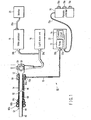
- an endoscopic system 10 includes an endoscope 12, an overtube (insertion aid) 14, a light source unit 16, a video processor 18, a monitor 20, and a balloon control unit (supply/discharge unit) 22.
- the endoscope 12 includes an elongate insertion section 32, and an operation section 34 provided at the proximal end of the insertion section 32, and a universal cord 36 extending from the operation section 34.
- the light source unit 16 is optically connected to a connector 36a at the end of the universal cord 36. Light emitted from the light source unit 16 exits from the distal end of the insertion section 32 via the universal cord 36, the operation section 34 and the insertion section 32.
- the video processor 18 is further electrically connected to a connector 36b at the end of the universal cord 36 extending in addition to the above-mentioned connector 36a.
- the monitor 20 is electrically connected to the video processor 18 via a cable 20a.
- the insertion section 32 includes a rigid distal portion 42, a bending portion 44 capable of vertically and horizontally bending, and a long and flexible tube portion 46.
- the rigid distal portion 42 is disposed at a most distal position of the insertion section 32.
- the rigid distal portion 42 is provided with a forceps opening communicating with an illumination optical system, an observation optical system such as the solid-state image sensing device, and a treatment tool insertion channel, and also provided with a nozzle for supplying air into a body cavity and water to an observation lens (neither the forceps opening nor the nozzle is shown).
- the treatment tool insertion channel communicates with a treatment tool insertion hole (not shown) of the operation section 34.
- the distal end of the bending portion 44 is coupled to the proximal end of the rigid distal portion 42.
- the distal end of the flexible tube portion 46 is coupled to the proximal end of the bending portion 44.
- the distal end of the operation section 34 is coupled to the proximal end of the flexible tube portion 46. That is, the distal end of the operation section 34 is coupled to the proximal end of the insertion section 32.
- the operation section 34 is provided with a remote switch 52 for the remote control of the video processor 18, etc., and a bending operation knob 54 rotated by an operator.
- a bending operation knob 54 rotated by an operator.
- the overtube 14 includes a main body (tube member) 62 disposed to cover the outer periphery of the insertion section 32 of the endoscope 12, a grip 64 provided at the proximal end of the main body 62, and first to third balloons 66a, 66b and 66c provided on the outer peripheral surface of the distal end of the main body 62.
- a balloon communication pipeline 68 is formed which communicates with the first to third balloons 66a, 66b and 66c.
- the distal end of the balloon communication pipeline 68 communicates with the first to third balloons 66a, 66b and 66c.
- the proximal end of the balloon communication pipeline 68 communicates with a connector 64a provided in the grip 64.
- a connection pipeline 70 is disposed between the overtube 14 and the balloon control unit 22.
- Connectors 70a and 70b are provided at one end and the other end of the connection pipeline 70, respectively.
- the connector 70a at one end of the connection pipeline 70 is connected to the connector 64a of the grip 64.
- the connector 70b at the other end of the connection pipeline 70 is connected to a connector 22a of the balloon control unit 22.
- the balloon control unit 22 includes a pump 72 capable of supplying/discharging (sucking) a gas, a control circuit 74 for controlling the pump 72, and a remote controller 76 electrically connected to the control circuit 74 via a connection cable 76a.
- This remote controller 76 is provided with a stop button 78a, a pressurization button 78b and a decompression button 78c.
- the stop button 78a When the stop button 78a is depressed, its signal is input to the control circuit 74. Then, the control circuit 74 stops the operation of the pump 72.
- the pressurization button 78b When the pressurization button 78b is depressed, its signal is input to the control circuit 74.
- control circuit 74 operates the pump 72 so that the gas is supplied from the connection pipeline 70 to the balloon communication pipeline 68 of the overtube 14.
- the decompression button 78c When the decompression button 78c is depressed, its signal is input to the control circuit 74. Then, the control circuit 74 operates the pump 72 so that the gas is discharged from the connection pipeline 70 and the balloon communication pipeline 68 of the overtube 14.
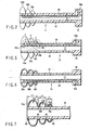
- the three first to third balloons 66a, 66b and 66c are disposed at the distal end of the overtube 14.
- the balloons 66a, 66b and 66c are formed of, for example, silicone rubber, latex rubber, or an elastic elastomer.
- the balloons 66a, 66b and 66c communicate with each other through the balloon communication pipeline 68 provided in the main body 62.
- the outside diameter of the first balloon 66a on the most distal side when inflated is formed to be greater than the outside diameter of the adjacent second balloon 66b when inflated.
- the outside diameter of the third balloon 66c adjacent to the second balloon 66b is formed to be smaller than that of the second balloon 66b when the second and third balloons 66b and 66c are inflated.
- the balloons 66a, 66b and 66c are formed of, for example, one cylindrical member.
- the distal end and proximal end of this cylindrical member are fixed by being wound and bound with, for example, threads 80 (see FIG. 7 ).
- the cylindrical member is wound and bound with the threads 80 at appropriate two places so that the first to third balloons 66a, 66b and 66c are formed.
- an adhesive is applied to the parts wound with the threads 80 for fixture.
- the first to third balloons 66a, 66b and 66c are formed.
- the insertion section 32 of the endoscope 12 is per anum inserted into the large intestine C shown in FIG. 3A , and the main body 62 of the overtube 14 is inserted.
- the pressurization button 78b of the remote controller 76 is depressed.
- a signal is input from the remote controller 76 to the control circuit 74 via the connection cable 76a.
- the control circuit 74 operates the pump 72 while controlling the pump 72.
- the balloons 66a, 66b and 66c of the overtube 14 are inflated so that the intestinal wall is expanded outward by the balloons 66a, 66b and 66c.
- the pump 72 is controlled by the control circuit 74 to adjust the velocity and amount of a fluid (gas), thereby slowly inflating the balloons 66a, 66b and 66c.
- the balloons 66a, 66b and 66c slowly expand the intestinal wall outward.
- the position of the overtube 14 is held to the large intestine C by frictional force between the balloons 66a, 66b and 66c and the inner wall of the intestine.
- the pressurization of the balloons 66a, 66b and 66c is automatically stopped when specified pressure is reached.
- the stop button 78a is depressed and its signal is input to the control circuit 74 before the specified pressure is reached.
- the control circuit 74 stops the operation of the pump 72.
- the intestinal wall is expanded outward so that the distal side of the first balloon 66a is also expanded.
- the insertion section 32 of the endoscope 12 is moved to the inner side of the large intestine C while the position of the overtube 14 is being held.
- the bending portion 44 of the insertion section 32 is caused to further project forward from the distal end of the main body 62 of the overtube 14.
- the bending operation knob 54 of the operation section 34 is operated to curve the bending portion 44 of the insertion section 32, as shown in FIG. 3D .
- the large intestine C deforms in an S-shape. Therefore, the large intestine C is held so that it is substantially caught between the bending portion 44 of the insertion section 32 of the endoscope 12 and the rigid distal portion 42.
- the decompression button 78c of the remote controller 76 is operated to operate the pump 72, and the balloons 66a, 66b and 66c of the overtube 14 are deflated, as shown in FIG. 4A .
- the pump 72 is controlled by the control circuit 74 to discharge the gas from the balloons 66a, 66b and 66c as fast as possible. Then, it is possible to quickly move on to the next operation.
- the overtube 14 is moved to the inner side along the insertion section 32 of the endoscope 12.
- the balloons 66a, 66b and 66c of the overtube 14 are inflated to expand the wall of the large intestine C.
- the balloons 66a, 66b and 66c are slowly inflated. Then, the position of the overtube 14 is fixed by the balloons 66a, 66b and 66c.
- the bending operation knob 54 of the operation section 34 of the endoscope 12 is operated to make the curved bending portion 44 of the insertion section 32 straight. That is, the holding of the large intestine C by the bending portion 44 of the insertion section 32 and the rigid distal portion 42 is released. Further, the overtube 14 and the insertion section 32 of the endoscope 12 are pulled together so that their relative movement is prevented. Then, using the balloons 66a, 66b and 66c in which the diameter is larger on the distal side and smaller on the proximal side, the large intestine C is pushed out to the hand side (anal side) by the proximal part of the third balloon 66c.
- the large intestine C is pushed out to the hand side by the proximal part of the second balloon 66b. Further, the large intestine C is pushed out to the hand side by the proximal part of the third balloon 66c. Then, the folds of the inner wall of the large intestine C are hooked between the first balloon 66a and the second balloon 66b, between the second balloon 66b and the third balloon 66c and by the proximal part of the third balloon 66c.
- the large intestine C is pulled to the hand side and efficiently folded (shortened) because the folds of the large intestine C are hooked by the balloons 66a, 66b and 66c.
- the insertion section 32 of the endoscope 12 is inserted into the inner side with respect to the overtube 14. Subsequently, similar operation is carried out to insert the distal end of the insertion section 32 into the inner side of the large intestine C.
- the plurality of balloons 66a, 66b and 66c are provided at the distal end of the overtube 14. Moreover, the diameter of the first balloon 66a is larger than the diameter of the second balloon 66b, and the diameter of the second balloon 66b is larger than the diameter of the third balloon 66c.
- the effect of hooking the inner wall of the large intestine C with the balloons 66a, 66b and 66c can be increased when the large intestine C is folded onto the anal side. Further, the area of contact with the intestinal wall in folding the large intestine C can be large. Thus, the force of fixing the balloons 66a, 66b and 66c to the wall of the large intestine C can be increased.
- This example useful for understanding the invention is a modification of the first example useful for understanding the invention, so that the same signs are assigned to the same members as those described in the first example useful for understanding the invention, and these members are not described in detail.
- First to third balloons 66a, 66b and 66c are formed into, for example, separate members, but are formed of the same material at about the same thickness.
- balloon communication holes 68a, 68b and 68c of the balloons 66a, 66b and 66c communicating with a balloon communication pipeline 68 have cross-sectional areas different from each other.
- the cross-sectional area ⁇ of the first balloon communication hole 68a providing communication between the first balloon 66a and the balloon communication pipeline 68 is formed to be the largest.
- the cross-sectional area P of the second balloon communication hole 68b providing communication between the second balloon 66b and the balloon communication pipeline 68 is formed to be smaller than that of the first balloon communication hole 68a.
- the cross-sectional area ⁇ of the third balloon communication hole 68c providing communication between the third balloon 66c and the balloon communication pipeline 68 is formed to be smaller than that of the second balloon communication hole 68b.
- the amount of gas flowing from the second balloon communication hole 68b into the second balloon 66b is greater than the amount of gas flowing from the third balloon communication hole 68c into the third balloon 66c.
- the amount of gas flowing from the first balloon communication hole 68a into the first balloon 66a is greater than the amount of gas flowing from the second balloon communication hole 68b into the second balloon 66b.
- the times for inflating the first to third balloons 66a, 66b and 66c can be about the same. Then, it is possible to prevent, for example, any one of the first to third balloons 66a, 66b and 66c from being in an overpressurized state or a low pressure state.
- the inflation amounts of the balloons 66a, 66b and 66c can be regulated by the cross-sectional areas ⁇ , ⁇ and ⁇ of the balloon communication holes 68a, 68b and 68c. That is, the relationships between the cross-sectional areas ⁇ , ⁇ and ⁇ of the first to third balloon communication holes 68a, 68b and 68c serve as means for regulating the inflation amounts of the balloons 66a, 66b and 66c so that one supply of gas causes the first balloon 66a to be inflated to the largest outside diameter, the second balloon 66b to be inflated to the second largest outside diameter, and the third balloon 66c to be inflated to the third largest outside diameter.
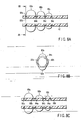
- FIGS. 6 and 7 a third example, which is an embodiment of the invention, will be described using FIGS. 6 and 7 .
- This embodiment is a modification of the first example, so that the same signs are assigned to the same members as those described in the first example, and these members are not described in detail.
- FIG. 7 shows first to third balloons 66a, 66b and 66c in a magnified manner so that an overtube 14 shown in FIG. 6 is rotated 90 degrees around the axis of a main body 62.
- the length L 1 from the distal end to proximal end of the first balloon 66a is formed to be larger than the length L 2 from the distal end to proximal end of the second balloon 66b. Further, the length L 2 from the distal end to proximal end of the second balloon 66b is formed to be larger than the length L 3 from the distal end to proximal end of the third balloon 66c.
- the length L 1 from the distal end to proximal end of the first balloon 66a is larger than the length L 2 from the distal end to proximal end of the second balloon 66b, such that the space in the first balloon 66a can be larger.
- a greater amount of fluid can be made to flow into the first balloon 66a than into the second balloon 66b.
- the outside diameter of the first balloon 66a on the distal side can be larger than that of the second balloon 66b on the proximal side.
- the inflation amounts of the balloons 66a, 66b and 66c can be regulated by the relationships between the lengths L 1 , L 2 and L 3 . That is, the relationships between the lengths L 1 , L 2 and L 3 of the first to third balloons 66a, 66b and 66c serve as means for regulating the inflation amounts of the balloons 66a, 66b and 66c so that one supply of gas causes the first balloon 66a to be inflated to the largest outside diameter, the second balloon 66b to be inflated to the second largest outside diameter, and the third balloon 66c to be inflated to the third largest outside diameter.
- first to third balloons 66a, 66b and 66c are formed of the same material but are different from each other in thickness.
- the thickness t 1 of the first balloon 66a is formed to be smaller than the thickness t 2 of the second balloon 66b.
- the thickness t 2 of the second balloon 66b is formed to be smaller than the thickness t 3 of the third balloon 66c.
- the times for inflating the first to third balloons 66a, 66b and 66c can be about the same. Then, it is possible to prevent, for example, any one of the first to third balloons 66a, 66b and 66c from being in an overpressurized state or a low pressure state.
- the first to third balloons 66a, 66b and 66c are formed of the same material, and the thickness t 1 of the first balloon 66a is formed to be smaller than the thickness t 2 of the second balloon 66b, and the thickness t 2 of the second balloon 66b is formed to be smaller than the thickness t 3 of the third balloon 66c.
- the inflation amounts of the balloons 66a, 66b and 66c can be regulated by the relationships between the thicknesses t 1 , t 2 and t 3 .
- the relationships between the thicknesses t 1 , t 2 and t 3 of the first to third balloons 66a, 66b and 66c serve as means for regulating the inflation amounts of the balloons 66a, 66b and 66c so that one supply of gas causes the first balloon 66a to be inflated to the largest outside diameter, the second balloon 66b to be inflated to the second largest outside diameter, and the third balloon 66c to be inflated to the third largest outside diameter.
- the same material is used and thickness is varied in the first to third balloons 66a, 66b and 66c so that their inflation times may be substantially equal to each other in this embodiment described above.
- the inflation times of the balloons 66a, 66b and 66c can also be made substantially equal to each other by setting these balloons at a substantially uniform thickness but using materials of different expansion rates (the first balloon 66a has the highest expansion rate and the third balloon 66c has the lowest expansion rate).
- the cross-sectional areas of the first to third balloon communication holes 68a, 68b and 68c shown in FIG. 6 may be the same or different from each other. The cross-sectional areas are properly set in relation to the thickness and the material.
- first to third balloons 66a, 66b and 66c can also be formed of one cylindrical member. This cylindrical member is formed so that the thickness becomes linearly greater from the distal side to the proximal side. Then, when the cylindrical member is fixed by threads 80 at appropriate positions, the positions of the balloons 66a, 66b and 66c are regulated. At this point, the outside diameters of the first to third balloons 66a, 66b and 66c can also be about the same when the balloons 66a, 66b and 66c are in a deflated state.
- the first to third balloons 66a, 66b and 66c are inflated when the cross-sectional areas of the first to third balloon communication holes 68a, 68b and 68c are the same. Then, the first balloon 66a is inflated into the largest size and the second balloon 66b is inflated into the second largest size because the first balloon 66a is formed thinner than the second and third 66b and 66c and because the second balloon 66b is formed thinner than the third balloon 66c.
- the third balloon 66c is formed at the largest thickness and is therefore inflated less.
- FIGS. 8A and 8B This example is a modification of the first example, so that the same signs are assigned to the same members as those described in the first example, and these members are not described in detail.
- each of first to third balloons 66a, 66b and 66c includes a pair of bags 82a and a pair of bands 82b.
- first to fourth grooves 84a, 84b, 84c and 84d are formed in the outer peripheral surface of a main body 62.
- the length L 1 between the first and second grooves 84a and 84b is formed to be larger than the length L 2 between the second and third grooves 84b and 84c.
- the length L 2 between the second and third grooves 84b and 84c is formed to be larger than the length L 3 between the third and fourth grooves 84c and 84d.
- the first balloon 66a is formed thinner than the second balloon 66b
- the second balloon 66b is formed thinner than the third balloon 66c.
- the times for inflating the first to third balloons 66a, 66b and 66c can be about the same. Then, it is possible to prevent, for example, any one of the first to third balloons 66a, 66b and 66c from being in an overpressurized state or a low pressure state.
- the second groove 84b is used in common by the proximal side of the first balloon 66a and the distal side of the second balloon 66b.
- the third groove 84c is used in common by the proximal side of the second balloon and the distal side of the third balloon 66c.
- grooves 92a, 92b, 94a, 94b, 96a and 96b shown in FIG. 8C are separately provided.
- the positions of the balloons 66a, 66b and 66c can be suitably set. That is, the distance between the balloons 66a, 66b and 66c can be suitably set.
Claims (6)
- Endoskopische Einführhilfe (14), die das Einführen eines Einführabschnitts (32) eines Endoskops (12) in die Innenwand eines Darms (C) unterstützt, mit:einem Rohrelement (62), das dazu ausgebildet ist, ein Einführen des Einführabschnitts (32) des Endoskops (12) durch es hindurch zu erlauben und die Längsbewegung des Einführabschnitts zu leiten;einer Anschlussleitung (68, 70), die in dem Rohrelement vorgesehen ist und so ausgebildet ist, dass sie mit einer Zuführ/Ableiteinheit (22) in Verbindung steht, zum Zuführen eines Fluids zum distalen Ende des Rohrelements oder zum Ableiten des Fluids vom distalen Ende des Rohrelements; understen, zweiten und dritten Ballonen (66a, 66b, 66c), die am Außenumfang des distalen Endes des Rohrelements in Längsrichtung entlang des Rohrelements so angeordnet sind, dass der erste Ballon (66a) der distalste und der dritte Ballon (66c) der proximalste der Ballone ist, und wobei die Ballone so ausgebildet sind, dass sie mit der Anschlussleitung in Verbindung stehen, und sich gemäß der Zufuhr/Ableitung des Fluids über die Anschlussleitung aufblasen und entleeren,wobei der erste Ballon (66a) einen größeren Durchmesser aufweist als der zweite Ballon (66b), und der zweite Ballon (66b) einen größeren Durchmesser aufweist als der dritte Ballon (66c), wenn die ersten bis dritten Ballone aufgeblasen sind,einer Regeleinrichtung (L1, L2, L3, t1, t2, t3; α, β, γ), die eine Regelung so ausführt, dass der erste Ballon (66a) zu einem Außendurchmesser aufgeblasen wird, der größer ist als der des zweiten und dritten Ballons (66b, 66c), und wobei der zweite Ballon (66b) einen Außendurchmesser hat, der größer ist als der des dritten Ballons (66c), wenn die ersten bis dritten Ballone aufgeblasen sind,dadurch gekennzeichnet, dass die Regeleinrichtung (L1, L2, L3) so angeordnet ist, dass die Länge (L1) vom distalen Ende zum proximalen Ende des auf der distalen Seite des Rohrelements (62) angeordneten ersten Ballons (66a) größer ist als die Länge (L3) vom distalen Ende zum proximalen Ende des dritten Ballons (66c), der der proximalen Seite des Rohrelements näher ist als der auf der distalen Seite angeordnete Ballon, und dass die Länge (L2) vom distalen Ende zum proximalen Ende des zwischen dem ersten und dritten Ballon (66a, 66c) liegenden zweiten Ballons (66b) geringer ist als die Länge (L1) des ersten Ballons (66a) und größer ist als die Länge (L3) des dritten Ballons (66c).
- Endoskopische Einführhilfe (14) nach Anspruch 1, dadurch gekennzeichnet, dass die Regeleinrichtung (t1, t2, t3) so angeordnet ist, dass das gleiche Material für die mehreren Ballone (66a, 66b, 66c) verwendet wird und so dass die Dicke (t1) des auf der distalen Seite des Rohrelements (62) angeordneten Ballons (66a) geringer ist als die Dicke (t3) des Ballons (66c), der näher zur proximalen Seite des Rohrelements angeordnet ist als der auf der distalen Seite angeordnete Ballon.
- Endoskopische Einführhilfe (14) nach einem der Ansprüche 1 bis 2, dadurch gekennzeichnet, dass von den mehreren Ballonen (66a, 66b, 66c) der auf der distalen Seite angeordnete Ballon (66a) aus einem Material besteht dessen Dehnrate größer ist als die des Ballons (66c), der näher zur proximalen Seite des Rohrelements angeordnet ist als der auf der distalen Seite angeordnete Ballon.
- Endoskopische Einführhilfe (14) nach einem der Ansprüche 1 bis 3, dadurch gekennzeichnet, dass
die Anschlussleitung (68, 70) aufweist:eine Verbindungsleitung (70), die mit der Zuführ/Ableiteinheit (22) verbunden ist, die das Fluid zum ersten bis dritten Ballon zuführt und von diesen ableitet; undeine Mehrzahl von Ballon-Kommunikationsleitungen (68), die zur Kommunikation mit den ersten bis dritten Ballonen von der Verbindungsleitung abzweigen und die das Fluid zum ersten bis dritten Ballon zuführen und von diesen ableiten; unddass von den Ballon-Kommunikationsleitungen die mit dem auf der distalen Seite des Rohrelements angeordneten Ballon (66a) in Verbindung stehende Ballon-Kommunikationsleitung (68a) dem Fluid weniger Widerstand bietet als die Ballon-Kommunikationsleitung (68c), die mit dem Ballon (66c) in Verbindung steht, der näher zur proximalen Seite des Rohrelements angeordnet ist als der auf der distalen Seite angeordnete Ballon. - Endoskopische Einführhilfe (14) nach Anspruch 4, dadurch gekennzeichnet, dass
von den Ballon-Kommunikationsleitungen (68a, 68b, 68c) die Querschnittsfläche (α) der Ballon-Kommunikationsleitung (68a), die mit dem Ballon (66a) in Verbindung steht, der auf der distalen Seite des Rohrelements (62) angeordnet ist, größer ist als die Querschnittsfläche (γ) der Ballon-Kommunikationsleitung (68c), die mit dem Ballon (66c) in Verbindung steht, der näher zur proximalen Seite des Rohrelements angeordnet ist als der auf der distalen Seite angeordnete Ballon. - Endoskopisches System (10), dadurch gekennzeichnet, dass es umfasst:ein Endoskop (12), wobei das Endoskop aufweist:einen langgestreckten Einführabschnitt (32) mit einem Biegebereich (44);einen Betätigungsbereich (34), der an dem proximalen Ende des Einführabschnitts vorgesehen ist und der dazu ausgebildet ist, den Biegebereich zu biegen; undeine endoskopische Einführhilfe (14) nach einem der Ansprüche 1 bis 5.
Applications Claiming Priority (1)
| Application Number | Priority Date | Filing Date | Title |
|---|---|---|---|
| JP2006210066A JP4885640B2 (ja) | 2006-08-01 | 2006-08-01 | 内視鏡用挿入補助具 |
Publications (2)
| Publication Number | Publication Date |
|---|---|
| EP1884187A1 EP1884187A1 (de) | 2008-02-06 |
| EP1884187B1 true EP1884187B1 (de) | 2013-02-27 |
Family
ID=38695541
Family Applications (1)
| Application Number | Title | Priority Date | Filing Date |
|---|---|---|---|
| EP07014085A Expired - Fee Related EP1884187B1 (de) | 2006-08-01 | 2007-07-18 | Endoskopische Einführhilfe und endoskopisches System |
Country Status (4)
| Country | Link |
|---|---|
| US (2) | US8403827B2 (de) |
| EP (1) | EP1884187B1 (de) |
| JP (1) | JP4885640B2 (de) |
| CN (1) | CN101116607B (de) |
Families Citing this family (43)
| Publication number | Priority date | Publication date | Assignee | Title |
|---|---|---|---|---|
| US8500628B2 (en) * | 2006-02-28 | 2013-08-06 | Olympus Endo Technology America, Inc. | Rotate-to-advance catheterization system |
| JP2008259701A (ja) * | 2007-04-12 | 2008-10-30 | Olympus Corp | 生体内挿入器具 |
| JP2008278968A (ja) * | 2007-05-08 | 2008-11-20 | Fujinon Corp | 内視鏡用挿入補助具 |
| US20090287049A1 (en) * | 2008-05-15 | 2009-11-19 | Jones Donald K | Access Systems Including Collapsible Port Body For Intra-Abdominal Surgery |
| US10149601B2 (en) | 2009-12-15 | 2018-12-11 | Lumendi Ltd. | Method and apparatus for manipulating the side wall of a body lumen or body cavity so as to provide increased visualization of the same and/or increased access to the same, and/or for stabilizing instruments relative to the same |
| US10485401B2 (en) | 2009-12-15 | 2019-11-26 | Lumendi Ltd. | Method and apparatus for manipulating the side wall of a body lumen or body cavity so as to provide increased visualization of the same and/or increased access to the same, and/or for stabilizing instruments relative to the same |
| WO2011084490A1 (en) | 2009-12-15 | 2011-07-14 | Cornell University | Method and apparatus for stabilizing, straightening, or expanding the wall of a lumen or cavity |
| US11877722B2 (en) | 2009-12-15 | 2024-01-23 | Cornell University | Method and apparatus for manipulating the side wall of a body lumen or body cavity |
| US9986893B2 (en) | 2009-12-15 | 2018-06-05 | Cornell University | Method and apparatus for manipulating the side wall of a body lumen or body cavity so as to provide increased visualization of the same and/or increased access to the same, and/or for stabilizing instruments relative to the same |
| CN102905608B (zh) | 2010-05-25 | 2015-11-25 | Arc医药设计有限公司 | 用于医疗内窥器械的覆盖物 |
| WO2011158227A2 (en) * | 2010-06-13 | 2011-12-22 | Omeq - Innovative Medical Devices Ltd | Anatomical-positioning apparatus and method with an expandable device |
| JP6023090B2 (ja) | 2011-02-16 | 2016-11-09 | ザ ジェネラル ホスピタル コーポレイション | 内視鏡用光学カプラ |
| WO2013117970A1 (en) * | 2012-02-06 | 2013-08-15 | HIROYUKI, Gomi | Movable balloon prosthesis for endoscopes |
| US8920313B2 (en) * | 2012-05-10 | 2014-12-30 | Promising Ground, Llc | Adjustable multifunctional medical examination instrument |
| JP6053358B2 (ja) * | 2012-07-03 | 2016-12-27 | オリンパス株式会社 | 手術支援装置 |
| CN103006165B (zh) * | 2012-12-14 | 2014-12-10 | 上海交通大学 | 刚度可变的柔性内窥镜机器人 |
| JP2016501622A (ja) * | 2012-12-24 | 2016-01-21 | サノバス・インコーポレイテッド | 固定式ワーキングチャンネル |
| CA2898997C (en) * | 2013-02-07 | 2020-05-05 | Endoaid Ltd. | Endoscopic sleeve |
| CN104994804B (zh) * | 2013-02-25 | 2017-07-04 | 奥林巴斯株式会社 | 手术工具保持装置、内窥镜和医疗系统 |
| US9839543B2 (en) * | 2013-03-14 | 2017-12-12 | Cook Medical Technologies Llc | Multi-stage balloon catheter |
| CN103393388A (zh) * | 2013-08-09 | 2013-11-20 | 广州宝胆医疗器械科技有限公司 | 内窥镜器械鞘 |
| CN103431828A (zh) * | 2013-08-09 | 2013-12-11 | 广州宝胆医疗器械科技有限公司 | 一种带充气气囊的宫腔镜 |
| CN103431835A (zh) * | 2013-08-09 | 2013-12-11 | 广州宝胆医疗器械科技有限公司 | 一种带充气气囊的关节镜 |
| CN103385688A (zh) * | 2013-08-09 | 2013-11-13 | 广州宝胆医疗器械科技有限公司 | 一种带充气气囊的乙状结肠镜 |
| CN103385685A (zh) * | 2013-08-09 | 2013-11-13 | 广州宝胆医疗器械科技有限公司 | 一种带充气气囊的阴道镜 |
| ES2726913T3 (es) * | 2014-02-11 | 2019-10-10 | Univ Cornell | Aparato para manipular la pared lateral de una luz corporal o de una cavidad corporal con el fin de proporcionar una mayor visualización de la misma y/o un mayor acceso a la misma y/o para estabilizar instrumental en relación con la misma |
| EP3078319A4 (de) * | 2014-05-29 | 2017-09-06 | Olympus Corporation | Endoskopsystem |
| CN106455933B (zh) * | 2014-06-20 | 2018-10-30 | 奥林巴斯株式会社 | 缆线连接构造和内窥镜装置 |
| US20170156571A1 (en) * | 2014-06-25 | 2017-06-08 | Mackay Memorial Hospital | Ultrathin endoscope auxiliary system and method of use |
| US9459442B2 (en) | 2014-09-23 | 2016-10-04 | Scott Miller | Optical coupler for optical imaging visualization device |
| JP6368256B2 (ja) * | 2015-02-05 | 2018-08-01 | 富士フイルム株式会社 | 内視鏡システム |
| WO2016136511A1 (ja) * | 2015-02-27 | 2016-09-01 | オリンパス株式会社 | 移動装置、及び、移動装置の移動方法 |
| US10548467B2 (en) | 2015-06-02 | 2020-02-04 | GI Scientific, LLC | Conductive optical element |
| US11553832B2 (en) * | 2015-06-05 | 2023-01-17 | Fujifilm Corporation | Endoscope system |
| KR20180041140A (ko) | 2015-07-21 | 2018-04-23 | 지아이 사이언티픽, 엘엘씨 | 각도 조정성 배출 포털을 갖는 내시경 부속품 |
| EP3329959B1 (de) * | 2015-07-28 | 2020-08-26 | Olympus Corporation | Behandlungsinstrument für endoskop |
| US10765304B2 (en) * | 2015-09-28 | 2020-09-08 | Bio-Medical Engineering (HK) Limited | Endoscopic systems, devices, and methods for performing in vivo procedures |
| WO2018010034A1 (de) | 2016-07-14 | 2018-01-18 | ILERI, Atilay | Vorrichtung zur unterstützenden verwendung bei einer koloskopischen untersuchung, insbesondere zum fixieren und vorzugsweise abdichten eines endoskops im bereich des analkanals und/oder des enddarms |
| DE102017202869A1 (de) * | 2017-02-22 | 2018-08-23 | OLYMPUS Winter & lbe GmbH | Aufbereitungsvorrichtung und Verfahren zum Betreiben einer Aufbereitungsvorrichtung zum Reinigen und/oder Desinfizieren eines medizinischen Instruments |
| CN107928606B (zh) * | 2017-12-11 | 2019-04-19 | 荣佳(惠州)医疗器械制造有限公司 | 一种医疗内窥镜套筒 |
| JP7270159B2 (ja) * | 2018-07-06 | 2023-05-10 | 株式会社塚田メディカル・リサーチ | 自然口拡張アプリケータ |
| CN111920366B (zh) * | 2020-06-24 | 2021-10-08 | 海南大学 | 一种含有固定装置的共聚焦内窥镜 |
| WO2023214414A1 (en) * | 2022-05-03 | 2023-11-09 | Gynecheck Ltd | Medical visualization and monitoring devices and methods |
Citations (1)
| Publication number | Priority date | Publication date | Assignee | Title |
|---|---|---|---|---|
| US5738629A (en) * | 1991-05-29 | 1998-04-14 | Origin Medsystems, Inc. | Self-retracting endoscope |
Family Cites Families (13)
| Publication number | Priority date | Publication date | Assignee | Title |
|---|---|---|---|---|
| US5514091A (en) | 1988-07-22 | 1996-05-07 | Yoon; Inbae | Expandable multifunctional manipulating instruments for various medical procedures |
| JPH0777576B2 (ja) * | 1991-03-27 | 1995-08-23 | 了司 服部 | 内視鏡の付属品及び内視鏡 |
| JP2656683B2 (ja) | 1991-08-29 | 1997-09-24 | 日本電気アイシーマイコンシステム株式会社 | 差動型入力回路 |
| JPH07265411A (ja) * | 1994-03-31 | 1995-10-17 | Terumo Corp | 血液補助循環装置 |
| JPH10155733A (ja) * | 1996-11-26 | 1998-06-16 | Olympus Optical Co Ltd | 内視鏡用挿入補助具 |
| US5951514A (en) * | 1997-03-07 | 1999-09-14 | Sahota; Harvinder | Multi-lobe perfusion balloon |
| US20020143237A1 (en) * | 2000-10-30 | 2002-10-03 | Katsumi Oneda | Inflatable member for an endoscope sheath |
| US7422579B2 (en) * | 2001-05-01 | 2008-09-09 | St. Jude Medical Cardiology Divison, Inc. | Emboli protection devices and related methods of use |
| JP4780543B2 (ja) * | 2001-09-19 | 2011-09-28 | Hoya株式会社 | 内視鏡用バルーン装置 |
| US20040186349A1 (en) * | 2002-12-24 | 2004-09-23 | Usgi Medical Corp. | Apparatus and methods for achieving endoluminal access |
| US20050080313A1 (en) * | 2003-10-10 | 2005-04-14 | Stewart Daren L. | Applicator for radiation treatment of a cavity |
| US20050159645A1 (en) * | 2003-11-12 | 2005-07-21 | Bertolero Arthur A. | Balloon catheter sheath |
| JP3804068B2 (ja) * | 2003-12-22 | 2006-08-02 | フジノン株式会社 | 内視鏡用挿入補助具 |
-
2006
- 2006-08-01 JP JP2006210066A patent/JP4885640B2/ja not_active Expired - Fee Related
-
2007
- 2007-07-18 EP EP07014085A patent/EP1884187B1/de not_active Expired - Fee Related
- 2007-07-18 CN CN2007101361350A patent/CN101116607B/zh not_active Expired - Fee Related
- 2007-07-18 US US11/779,601 patent/US8403827B2/en active Active
-
2010
- 2010-12-21 US US12/974,911 patent/US20110092770A1/en not_active Abandoned
Patent Citations (1)
| Publication number | Priority date | Publication date | Assignee | Title |
|---|---|---|---|---|
| US5738629A (en) * | 1991-05-29 | 1998-04-14 | Origin Medsystems, Inc. | Self-retracting endoscope |
Also Published As
| Publication number | Publication date |
|---|---|
| US8403827B2 (en) | 2013-03-26 |
| JP2008035908A (ja) | 2008-02-21 |
| CN101116607A (zh) | 2008-02-06 |
| JP4885640B2 (ja) | 2012-02-29 |
| CN101116607B (zh) | 2010-07-21 |
| US20110092770A1 (en) | 2011-04-21 |
| US20080033246A1 (en) | 2008-02-07 |
| EP1884187A1 (de) | 2008-02-06 |
Similar Documents
| Publication | Publication Date | Title |
|---|---|---|
| EP1884187B1 (de) | Endoskopische Einführhilfe und endoskopisches System | |
| JP5019757B2 (ja) | バルーン制御装置 | |
| JP4981344B2 (ja) | 内視鏡装置用バルーンユニット | |
| US8092372B2 (en) | Insertion assisting tool for endoscope and endoscope operating method | |
| EP2157996B1 (de) | Katheter mit einem biegbaren teil | |
| US8012084B2 (en) | Endoscope device and control method for the same | |
| JP4874724B2 (ja) | 内視鏡装置 | |
| EP2364637A1 (de) | Überrohr mit einem Ballon und einem Endoskopsystem | |
| JP4836653B2 (ja) | 内視鏡装置 | |
| JP2007307036A (ja) | 内視鏡 | |
| WO2008048941A2 (en) | Inflatable actuation device | |
| US8409078B2 (en) | Endoscope | |
| JP2007268137A (ja) | 大腸用内視鏡装置 | |
| JP3888359B2 (ja) | 内視鏡装置 | |
| JP3879857B2 (ja) | 内視鏡装置 | |
| JP4504003B2 (ja) | 内視鏡挿入補助装置 | |
| JP2008206693A (ja) | 医療器具用バルーン | |
| US20160309986A1 (en) | Endoscope system | |
| JP3864280B2 (ja) | ダブルバルーン式内視鏡装置 | |
| JP5400841B2 (ja) | 内視鏡システム | |
| JP2007330468A (ja) | 内視鏡用カバー及びそれを備えた内視鏡装置 | |
| JP3874293B2 (ja) | 内視鏡装置 | |
| JP2009160093A (ja) | バルーン装着装置 | |
| JP2009160219A (ja) | バルーン、バルーン内視鏡、バルーン装着方法 | |
| JP2008023102A (ja) | 内視鏡 |
Legal Events
| Date | Code | Title | Description |
|---|---|---|---|
| PUAI | Public reference made under article 153(3) epc to a published international application that has entered the european phase |
Free format text: ORIGINAL CODE: 0009012 |
|
| AK | Designated contracting states |
Kind code of ref document: A1 Designated state(s): AT BE BG CH CY CZ DE DK EE ES FI FR GB GR HU IE IS IT LI LT LU LV MC MT NL PL PT RO SE SI SK TR |
|
| AX | Request for extension of the european patent |
Extension state: AL BA HR MK YU |
|
| 17P | Request for examination filed |
Effective date: 20080402 |
|
| 17Q | First examination report despatched |
Effective date: 20080526 |
|
| AKX | Designation fees paid |
Designated state(s): DE FR GB |
|
| GRAP | Despatch of communication of intention to grant a patent |
Free format text: ORIGINAL CODE: EPIDOSNIGR1 |
|
| RAP1 | Party data changed (applicant data changed or rights of an application transferred) |
Owner name: OLYMPUS MEDICAL SYSTEMS CORPORATION |
|
| GRAS | Grant fee paid |
Free format text: ORIGINAL CODE: EPIDOSNIGR3 |
|
| GRAP | Despatch of communication of intention to grant a patent |
Free format text: ORIGINAL CODE: EPIDOSNIGR1 |
|
| RIN1 | Information on inventor provided before grant (corrected) |
Inventor name: TAKASE, SEISUKE Inventor name: MATSUI, RAIFU Inventor name: MATSUURA, NOBUYUKI Inventor name: KIMURA, HIDENOBU Inventor name: YOSHIDA, TAKATOSHI |
|
| RIN1 | Information on inventor provided before grant (corrected) |
Inventor name: MATSUI, RAIFU Inventor name: KIMURA, HIDENOBU Inventor name: TAKASE, SEISUKE Inventor name: YOSHIDA, TAKATOSHI Inventor name: MATSUURA, NOBUYUKI |
|
| GRAA | (expected) grant |
Free format text: ORIGINAL CODE: 0009210 |
|
| AK | Designated contracting states |
Kind code of ref document: B1 Designated state(s): DE FR GB |
|
| REG | Reference to a national code |
Ref country code: GB Ref legal event code: FG4D |
|
| REG | Reference to a national code |
Ref country code: DE Ref legal event code: R096 Ref document number: 602007028634 Country of ref document: DE Effective date: 20130425 |
|
| PLBE | No opposition filed within time limit |
Free format text: ORIGINAL CODE: 0009261 |
|
| STAA | Information on the status of an ep patent application or granted ep patent |
Free format text: STATUS: NO OPPOSITION FILED WITHIN TIME LIMIT |
|
| 26N | No opposition filed |
Effective date: 20131128 |
|
| REG | Reference to a national code |
Ref country code: DE Ref legal event code: R097 Ref document number: 602007028634 Country of ref document: DE Effective date: 20131128 |
|
| GBPC | Gb: european patent ceased through non-payment of renewal fee |
Effective date: 20130718 |
|
| REG | Reference to a national code |
Ref country code: FR Ref legal event code: ST Effective date: 20140331 |
|
| PG25 | Lapsed in a contracting state [announced via postgrant information from national office to epo] |
Ref country code: GB Free format text: LAPSE BECAUSE OF NON-PAYMENT OF DUE FEES Effective date: 20130718 |
|
| PG25 | Lapsed in a contracting state [announced via postgrant information from national office to epo] |
Ref country code: FR Free format text: LAPSE BECAUSE OF NON-PAYMENT OF DUE FEES Effective date: 20130731 |
|
| REG | Reference to a national code |
Ref country code: DE Ref legal event code: R082 Ref document number: 602007028634 Country of ref document: DE Representative=s name: WUESTHOFF & WUESTHOFF, PATENTANWAELTE PARTG MB, DE Ref country code: DE Ref legal event code: R081 Ref document number: 602007028634 Country of ref document: DE Owner name: OLYMPUS CORPORATION, JP Free format text: FORMER OWNER: OLYMPUS MEDICAL SYSTEMS CORP., TOKYO, JP |
|
| PGFP | Annual fee paid to national office [announced via postgrant information from national office to epo] |
Ref country code: DE Payment date: 20170711 Year of fee payment: 11 |
|
| REG | Reference to a national code |
Ref country code: DE Ref legal event code: R119 Ref document number: 602007028634 Country of ref document: DE |
|
| PG25 | Lapsed in a contracting state [announced via postgrant information from national office to epo] |
Ref country code: DE Free format text: LAPSE BECAUSE OF NON-PAYMENT OF DUE FEES Effective date: 20190201 |