EP1878623A1 - Impact absorbing member for vehicle - Google Patents
Impact absorbing member for vehicle Download PDFInfo
- Publication number
- EP1878623A1 EP1878623A1 EP07106316A EP07106316A EP1878623A1 EP 1878623 A1 EP1878623 A1 EP 1878623A1 EP 07106316 A EP07106316 A EP 07106316A EP 07106316 A EP07106316 A EP 07106316A EP 1878623 A1 EP1878623 A1 EP 1878623A1
- Authority
- EP
- European Patent Office
- Prior art keywords
- main body
- absorbing member
- impact absorbing
- flange
- vehicle according
- Prior art date
- Legal status (The legal status is an assumption and is not a legal conclusion. Google has not performed a legal analysis and makes no representation as to the accuracy of the status listed.)
- Granted
Links
- 238000003466 welding Methods 0.000 claims description 34
- 230000002093 peripheral effect Effects 0.000 claims description 14
- 238000006073 displacement reaction Methods 0.000 description 6
- 230000007423 decrease Effects 0.000 description 5
- 238000005452 bending Methods 0.000 description 4
- 230000004048 modification Effects 0.000 description 4
- 238000012986 modification Methods 0.000 description 4
- 229910000975 Carbon steel Inorganic materials 0.000 description 2
- 241000219122 Cucurbita Species 0.000 description 2
- 235000009852 Cucurbita pepo Nutrition 0.000 description 2
- 229910000831 Steel Inorganic materials 0.000 description 2
- 238000010521 absorption reaction Methods 0.000 description 2
- 230000015572 biosynthetic process Effects 0.000 description 2
- 239000010962 carbon steel Substances 0.000 description 2
- 238000009877 rendering Methods 0.000 description 2
- 239000010959 steel Substances 0.000 description 2
- 230000004323 axial length Effects 0.000 description 1
- VYQRBKCKQCRYEE-UHFFFAOYSA-N ctk1a7239 Chemical compound C12=CC=CC=C2N2CC=CC3=NC=CC1=C32 VYQRBKCKQCRYEE-UHFFFAOYSA-N 0.000 description 1
- 239000000463 material Substances 0.000 description 1
- 239000002184 metal Substances 0.000 description 1
- 238000000034 method Methods 0.000 description 1
- 238000000465 moulding Methods 0.000 description 1
- 230000002787 reinforcement Effects 0.000 description 1
- 229920003002 synthetic resin Polymers 0.000 description 1
- 239000000057 synthetic resin Substances 0.000 description 1
Images


Classifications
-
- F—MECHANICAL ENGINEERING; LIGHTING; HEATING; WEAPONS; BLASTING
- F16—ENGINEERING ELEMENTS AND UNITS; GENERAL MEASURES FOR PRODUCING AND MAINTAINING EFFECTIVE FUNCTIONING OF MACHINES OR INSTALLATIONS; THERMAL INSULATION IN GENERAL
- F16F—SPRINGS; SHOCK-ABSORBERS; MEANS FOR DAMPING VIBRATION
- F16F7/00—Vibration-dampers; Shock-absorbers
- F16F7/12—Vibration-dampers; Shock-absorbers using plastic deformation of members
-
- B—PERFORMING OPERATIONS; TRANSPORTING
- B60—VEHICLES IN GENERAL
- B60R—VEHICLES, VEHICLE FITTINGS, OR VEHICLE PARTS, NOT OTHERWISE PROVIDED FOR
- B60R19/00—Wheel guards; Radiator guards, e.g. grilles; Obstruction removers; Fittings damping bouncing force in collisions
- B60R19/02—Bumpers, i.e. impact receiving or absorbing members for protecting vehicles or fending off blows from other vehicles or objects
- B60R19/24—Arrangements for mounting bumpers on vehicles
- B60R19/26—Arrangements for mounting bumpers on vehicles comprising yieldable mounting means
- B60R19/34—Arrangements for mounting bumpers on vehicles comprising yieldable mounting means destroyed upon impact, e.g. one-shot type
Definitions
- the present invention relates to an impact absorbing member for vehicle.
- it relates to the impact absorbing member which can be suitably fixedly welded to an attaching plate even when thickness of a main body thereof is thin, and which is light-weight and low-price.
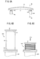
- FIG. 6 is a set of views explaining one example of such the impact absorbing member for vehicle.
- Fig. 6A is a schematic plan view in which a front bumper beam 10 and members therearound of the vehicle are viewed from an upper part.
- the crush box 14R includes a main body 20 and a pair of attaching plates 22, 24 welded thereto.
- the main body 20 has a hollow cylindrical shape such as an octagonal sectional shape.
- Each of the attaching plates 22, 24 is fixedly welded to each of axial ends of the main body 20 integral therewith.
- the crush box 14R is, at both axial ends thereof, fixed to the side member 12R and the bumper beam 10 via the attaching plates 22, 24 with bolts (not shown).
- the main body 20 crushes or deforms axially into the bellows shape.
- the main body 20 absorbs an impact energy to thereby buffer the impact applied to structural members of the vehicle such as the side member 12R.
- the crush or deformation into the bellows shape is a phenomenon that the main body 20 is subjected to a buckling at plural points (L-shape minute folds shown in Fig. 6C.
- the buckling begins from the axial end of the crush box 14R which comes close to the bumper beam 16, that is a load inputting side thereof, and progresses toward a vehicle body as lapse of time.
- the bumper beam 10 is right-and-left symmetrical, and a left attaching portion is constructed in the same manner as the right attaching portion.
- the bumper beam 10 functions as a reinforcement and an attaching member for the bumper, and to the bumper beam 10 a bumper main body 16 made of synthetic resin and the like is attached integrally.
- Figs. 7A to 7C are views for explaining some modes of a fixedly welded portion between the above main body 20 and one of the attaching plates 22, 24 (Fig.7 shows the attaching plate 22).
- Fig. 7A, Fig. 7B and Fig. 7C an upper view is a perspective view, and a lower view is a sectional view of the fixedly welded portion.
- Fig. 7A shows a case where an axial end of the main body 20 is butted to the attaching plate 22, and a L-shaped bracket 30 is spot-welded to both the main body 20 and the attaching plate 22 to join them each other.
- Fig. 7A shows a case where an axial end of the main body 20 is butted to the attaching plate 22, and a L-shaped bracket 30 is spot-welded to both the main body 20 and the attaching plate 22 to join them each other.
- Fig. 7A shows a case where an axial end of the main body 20 is butted to the attaching plate 22, and a L-shaped bracket 30
- FIG. 7B shows a case where an axial end of the main body 20 is bent outwardly in a right angle to form a flange 32 integrally to be fixed to the attaching plate 22 by a spot-welding.
- Fig. 7C shows a case where an axial end of the main body 20 is butted to the attaching plate 22 in a right angle to be fixed by an arc-welding to the attaching plate 22 integrally.
- Fig. 7C where the arc-welding is performed with the axial end of the main body 20 being butted to the attaching plate 22, unnecessity of the bracket and the like enables the main body 20 to be constructed in light-weight and low-price, and to exhibit a desired impact energy absorbing ability stably.
- thickness of the main body 20 is thin, following drawbacks may be caused. That is, the main body 20 of thin thickness may be melted to form a hole thereon, or may be thinned to lower the strength thereof, upon the welding. To avoid such drawback, the main body 20 is required to have the thickness of about 1.4 mm or more.
- the main body 20 For satisfying the above requirement, it is conceivable to thin the main body 20, with maintaining the desired impact energy absorbing ability by contriving a shape thereof and the like. Also conceivable is thinning the main body 20 for purpose of absorbing the impact energy by a small load.
- the small load is applied for example by the impact in a low vehicle speed of about 15 km/h or less, and the main body 20 deforms to decrease a damage of the vehicle.
- the main body 20 is fixedly welded to the attaching member 22 by the arc-welding with the axial end thereof being butted to the attaching member 22, similar to the above-mentioned case, so that there was a problem that the thickness of the main body 20 can be hardly thinned below 1.4 mm.
- the present invention is made in view of the above-mentioned circumstances. It is therefore an object of the present invention to provide an impact absorbing member for vehicle, which can realize a desired impact energy absorbing ability, and which is light-weight and low-price, by fixedly arc-welding the main body to the attaching plate suitably even when thickness thereof is thinner than 1.4 mm.
- the present invention relates to an impact absorbing member for vehicle which has a hollow cylindrical shape and is disposed in a vehicle between a side member and a bumper beam, and which is axially crushed by receiving a compressive force into a bellows shape to absorb an impact energy upon deformation
- the impact absorbing member includes a main body of a hollow cylindrical shape, and a pair of attaching plates to which both axial ends of the main body are fixedly welded respectively
- the main body has, at least one axial end thereof, a flange protruding at least axially and being integrally formed therewith
- the attaching plate has a adhered supporting portion, formed in parallel to the flange to be surface contacted therewith
- the main body is fixedly welded to the attaching plate with the flange being surface contacted with the adhered supporting portion.
- the flange is formed integrally therewith to protrude at least axially, and is fixedly welded to the attaching plate integrally with the axial end thereof being surface contacted with the adhered supporting portion of the attaching plate.
- the impact absorbing member realizing the desired impact energy absorbing ability can be constructed in light-weight and low-price on account of unnecessity of the bracket and the like.
- the thinnable main body can bring following two advantages. The first advantage is, in the case where the sectional shape is contrived to thin the main body with maintaining the impact energy absorbing ability, the main body is thinned below 1.4 mm to achieve further light-weight.
- the second advantage is, in the case where the main body is thinned for the purpose of absorbing the impact energy under low load upon a collision in the low vehicle speed to decrease a vehicle damage, the main body is thinned below 1.4 mm to be crushed with low load, thereby obtaining the impact energy absorbing operation.
- an expression that the flange "protruding at least axially” means the protruding direction of the flange has an axial component, and does not exclude having a radial component.
- the protruding direction of the flange has both the axial component and the radial component, the flange makes, as it protrudes radially outwardly or radially inwardly, a predetermined angle ⁇ relative to the main body of hollow cylindrical shape or an axis thereof.
- the flange protrudes outwardly from the hollow cylindrical shape relative to an axis of the main body to make an incline angle ⁇ ranging from zero to sixty degrees (0° ⁇ ⁇ ⁇ 60°).
- the incline angle of the flange protruded outwardly relative the main body or the axis thereof is selected to be from zero to sixty degrees (0° ⁇ ⁇ ⁇ 60°)
- a bending deformation of the main body upon application of the compressive load is prevented more securely, so that the desired impact absorbing ability can be obtained stably.
- the flange can be embodied in various modes, other than the above mode, as will be explained later.
- a fillet-welding is performed along a top periphery of the flange, so that the flange is fixedly welded to the adhered supporting portion integrally.
- the flange is fixedly welded integrally to the adhered supporting portion by performing the fillet-welding along the top periphery of the flange.
- the fillet welding can be the arc-welding easily performed from an outside of the main body. This is different from the spot welding (resistance welding) in which an overlapped portion between the flange and the adhered supporting portion are fixedly welded. Noted that the welding can be embodied in various modes, other than the above mode, as will be explained later.
- the attaching plate has a swell portion formed by subjecting a part to be positioned inside of the hollow cylindrical shape to a drawing to swell toward the main body, and an outer peripheral wall of the swell portion forms the adhered supporting portion.
- the part of the attaching plate positioned inside of the hollow cylindrical shape of the main body is swelled toward the main body by the drawing, so that the outer peripheral wall of the swell portion forms the adhered supporting portion.
- the adhered supporting portion has higher rigidity than the adhered supporting portion formed by bending up the cut part of the attaching plate, thereby rendering the excellent supporting strength.
- the attaching plate can be embodied in various modes, other than the above mode, as will be explained later.
- the impact absorbing member for vehicle of the present invention can be applied to both the attaching portion of the bumper beam attached to the vehicle front side and the attaching portion of the bumper beam attached to the vehicle rear side, but it can be applied to only one of them.
- the front bumper beam can preferably have a slightly curved shape where a longitudinally central portion thereof is protruded forwardly.
- the front bumper beam can have various modification such as a substantially linear shape, or a shape where only the both longitudinal ends are inclined or bent rearward.
- the fixedly welding manner of the present invention can be applied to any one of the fixedly welding portions between the main body and the paired attaching plates, for example to the load inputting side thereof.
- the above mentioned fixedly welding and fixing structure shown in Figs. 7A and 7B can be adopted for the other fixedly welded portion.
- the both axial ends of the main body are preferably provided with the flanges each projecting axially
- the paired attaching plate are preferably provided with the adhered supporting portion for applying the present invention to the both fixedly welded portions.
- the flange is preferably provided on an entire periphery of the main body, but it can be divided into plural flange portions depending on the sectional shape of the main body. For example, only four flange portions are sufficiently provided at right and left portions, as well as upper and lower portions of the main body. Other various modifications can be adopted for the flange.
- the flange incline angle ⁇ ranging from zero to sixty degrees (0° ⁇ ⁇ 60°), it is more preferable that the incline angle ranges from five to forty degrees (5° ⁇ ⁇ ⁇ 40°), and the adhered supporting portion is formed by an inclined surface inclined outward of the hollow cylindrical shape.
- the flange upon carrying out the present invention, can be inclined inside of the hollow cylindrical shape.
- the fillet-welding is performed along the top periphery of the flange to fixedly weld the flange to the adhered supporting portion.
- the adhered overlapped portions between the flange and the adhered supporting portion can be fixedly welded by the spot-welding.
- both the fillet-welding and the spot-welding can be used together.
- the fillet-welding the arc-welding is preferably used as the fillet-welding.
- the swell portion swelled toward the main body is provided to form the adhered supporting portion.
- an annular concave groove concaved in an opposite direction to the main body can be provided corresponding to the sectional shape of the main body, so that an inner peripheral wall surface is used as the adhered supporting portion.
- a cut part(s) of the attaching plate can be bent up to form the adhered supporting portion.
- Other various modification can be adopted for the adhered supporting portion.
- the main body preferably satisfies following two conditions.
- a first condition is that the sectional view perpendicular to the axis of the hollow cylindrical shape has a flat polygonal which is more than a hexagon and which includes at least two parallel sides.
- a second condition is that a pair of side walls constructing at least two parallel sides in the polygonal sectional view are provided with respectively a concave groove concaved inwardly and extending axially.
- the main body can have various sectional shape , such as a square, rectangle, simple square shape more than pentagon with no concave groove, circular, or ellipse.
- Provision of the concave grooves and convex projections extending axially about the axis of the hollow cylindrical shape with a predetermined pitch, can thin the main body and lighten the weight, with maintaining the desired impact energy absorbing quality.
- the number and position of the concave grooves and that of the convex projections can be optionally determined, but they are preferably provided symmetrical with respect to the axis (more accurately, with respect to a plane including the axis) of the main body.
- notches, grooves, projections can be provided with a predetermined pitch in the axial direction, if needed.
- the main body can have a flat octagon in the sectional view perpendicular to the axis of the hollow cylindrical shape, and on a pair of side walls constructing two long sides parallel to a long axis of the sectional view, concave grooves of the number of two or more are provided symmetrical with respect the long axis.
- Such the main body can be comprised of for example a pair of half pieces divided by a plane including the axis or a plane substantially parallel thereto of the hollow cylindrical shape. That is, each of the half pieces of substantially U-shape in the sectional view is formed by pressing a sheet plate and the like, and they are fixedly welded each other integrally with overlapping both side edges at open sides with each other.
- a hollow pipe member of circular shape or square shape can be subjected to a hydraulic molding to form the main body of predetermined sectional view. Other various modifications can be adopted for the main body.
- the present invention is preferably applied to the main body (the main body constructed by forming a sheet plate (for example, steel plate) is also included) of which thickness is below 1.4 mm. However, even for the main body of which thickness is 1.4 mm or more, the present invention can be applied.
- a material for the main body a rolled steel plate and a carbon steel tube can be preferably used for example, and other various metal plates and pipes can be adopted to render the desired impact energy absorbing operation by the crush into the bellows shape thereof.
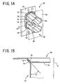
- Fig. 1 is a set of views explaining the impact absorbing member for vehicle according to one embodiment of the present invention, in which Fig. 1A is a perspective view with this side attaching plate being omitted, and Fig. 1B is a sectional view taken along a line 1B-1B in Fig. 1 A.
- a crush box 50 shown in Fig. 1 is disposed between the side member 12R and the bumper beam 10 to be used instead of the crush box 14R shown in Fig.6, and corresponds to the claimed impact absorbing member for vehicle.
- This crush box 50 includes a main body 52 of hollow cylindrical shape and a pair of attaching plates 54, 56 fixedly welded respectively to both axial ends of the main body 52 integrally.
- the crush box 50 is disposed between the side member 12R and the bumper beam 10 in a posture where an axis of the main body 52 is substantially parallel to a front-and-rear direction of the vehicle, and fixed integrally to the side member 12R and the bumper beam 10 via attaching plates 54, 56 by bolts and the like (not shown).
- the crush box 50 when receiving the compressive load from the vehicle front side resulting from the impact, crushes axially into the bellows shape in the same manner as the above-mentioned crush box 14R shown in Fig.6(c). During the deformation, the crush box 50 absorbs the impact energy to buffer the impact applied to structural members such as the side member 12R and the like of the vehicle.
- Fig. 1A is a perspective view of the main body 52
- Fig. 1B is a sectional view taken along a line 1B-1B in Fig. 1A, that is the sectional view showing a fixedly welded portion between the main body 52 and the attaching plate 56
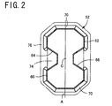
- Fig. 2 is a sectional view in which the main body 52 is cut at an axially intermediate portion thereof perpendicular to the axis thereof and views the attaching plate 56.
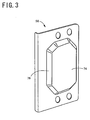
- Fig. 3 is a perspective view of the attaching plate 56 viewed from a side where the main body 52 is attached thereto.
- the main body 52 of a predetermined shape is molded by subjecting for example a hollow cylindrical pipe member (carbon steel tube) to a hydraulic forming.
- a hollow cylindrical pipe member carbon steel tube
- a basic shape defined by a section perpendicular to the axis of the hollow cylindrical shape has a flat octagonal shape (a shape in which four corners of a rectangle are chamfered).
- a pair of side walls 60, 62 constructing two long sides (right-and-left sides in Fig. 2) substantially parallel to a direction of a long axis A, that is the direction of a plane including the axis C (up-and-down direction in Fig. 2) of the sectional view at an axially intermediate portion, a pair of concave grooves 64, 66 are formed to be concaved inwardly of the hollow cylindrical shape symmetrical with respect to the axis.
- the main body 52 has as a whole a sectional shape of figure "8" or gourd.
- a hydraulic pressure is applied to an inside of the pipe member for example to plastically deform it outwardly.
- the pipe member is fitted to a female mold to be deformed into the predetermined sectional shape.
- a compressive force or a tensile force is axially applied to the main body upon the hydraulic forming, if needed.
- the main body 52 thus molded has thickness of about 1.2 mm which is thinner than 1.4 mm.
- the up-and-down direction in Fig.2 corresponds to an up-and-down direction in a state where the main body 52 is mounted onto the vehicle.
- flanges 68, 70 each protruding axially are provided integrally therewith.
- the flange 70 protruding at the side of the attaching plate 56 will be explained in detail.
- the flange 70 is provided around the main body 52 except areas corresponding to the concave grooves 64, 66.
- the flange 70 protrudes outwardly of the hollow cylindrical shape to make an incline angle ⁇ ranging from zero to sixty degrees (0° ⁇ ⁇ ⁇ 60°).
- Fig. 1 and Fig. 2 show the case where the incline angle ⁇ has a positive value, and the flange 70 in inclined outwardly from the hollow cylindrical shape.
- the attaching plate 56 is provided with a swell portion 74 at a predetermined position. That is, the swell portion 74 is formed by subjecting a part of the attaching plate 56 to be positioned inside of the hollow cylindrical shape of the main body 52 to the drawing. More specifically, the part of the attaching plate 56 to be positioned inside of the flat octagonal shape which is the basic sectional shape of the main body 52 is swelled by the drawing toward the main body 52 to form the swell portion 74.
- the swell portion 74 has a protruded flat surface of a trapezoidal shape, and an incline angle ⁇ of the outer peripheral wall 76 is selected to be 0° ⁇ ⁇ ⁇ 60°, so that the outer peripheral wall 76 is parallel to the above-mentioned flange 70.
- the flange 70 is surface contacted with the outer peripheral wall 76.
- the fillet-welding 78 is performed by the arc-welding along the top periphery of the flange 70, thereby being fixedly welded to the attaching plate 56 integrally.
- the outer peripheral wall 76 functions as the claimed adhered supporting portion.
- flange 68 is constructed in the same manner as the flange 70. That is, the flange 68 protrudes outwardly from the hollow cylindrical shape relative to the axial direction of the main body 52 to make the incline angle ⁇ to be 0° ⁇ ⁇ ⁇ 60° .
- An attaching plate 54 is provided with a swell portion which has the same structure as the swell portion 74. With the flange 68 being surface contacted with an outer peripheral wall (adhered supporting portion) of the swell portion, the fillet-welding is performed by the arc-welding along a top periphery thereof. Thus, the flange 68 is fixedly welded to the swell portion 74 of the attaching plate 54 integrally.
- the main body 52 of hollow cylindrical shape is provided with the flanges 68, 70 respectively formed at both axial ends of the main body 52 to protrude axially.
- These flanges 68, 70 are surface contacted with the outer peripheral walls 76 of the swell portions 74 respectively formed on the attaching plates 54, 56.
- the flanges 68, 70 can be suitably arc-welded to the attaching plates 54, 56 even when thickness of the main body 52 is thin.
- the crush box 54 rendering the desired impact energy absorbing quality can be obtained in light-weight and in low-price.
- the main body 52 of thin thickness can be fixedly welded to the attaching plates 54, 56 suitably, by contriving the sectional shape thereof as shown in Fig.2, thickness can be made thinner than 1.4 mm with maintaining the desired impact energy absorbing ability. In this way, weight of the main body 52 is further lightened.
- thickness of the main body 52 when thickness of the main body 52 is made thin for the purpose of absorbing impact energy under the low load, for example to decrease damage of the vehicle upon impact in the low speed, thickness of the main body 52 can be made thinner below 1.4 mm. In this way, the main body 52 crushes even with the low load to render the impact energy absorbing operation.
- the inclined angle ⁇ of the flanges 68, 70 protruding outwardly from the hollow cylindrical shape relative to the axial direction of the main body 52 is selected to be 0° ⁇ ⁇ ⁇ 60° . Accordingly, the desired impact energy absorbing ability can be obtained stably, different from the case shown in Fig. 7B in which the flange bent at the right angle is fixedly welded to the attaching plate and which suffers from the drawback of the main body being bend upon inputting of the load thereto.
- the flanges 68, 70 are easily fixedly welded to the outer peripheral wall 76 of the swell portion 74 integrally. Accordingly, the fixedly welding can be performed by the arc-welding from outside of the main body 52 easily, different from the case where the overlapped portion between the flanges 68, 70 and the outer peripheral wall 76 is fixedly welded by the spot-welding.
- each attaching plate 54, 56 to be positioned inside of the hollow cylindrical shape of the main body 52 is swelled toward the main body 52 by the drawing, so that the outer peripheral wall 76 of the swell portion 74 forms the adhered supporting portion to which the flanges 68, 70 are fixedly welded. For this reason, compared with the case where the part of each attaching plate 54, 56 is cut and bent-up to form the adhered supporting portion, the supporting portion of high rigidity can render the excellent supporting strength.
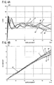
- Fig. 4A is a graph showing a relation between the load and the displacement
- Fig. 4B is a graph showing a relation between EA (energy absorption) amount corresponding to an integrated value of the load shown in Fig. 4A and the displacement.
- the main body 52 has the thickness of 1.2 mm, the axial length of 150 mm, the up-and-down dimension in Fig. 2 being 100 mm, and the right-and-left dimension in Fig.2 being 60 mm, respectively.
- the energy absorbing amount decreases in the displacement amount larger than 70 mm.
- the crush boxes 50 began to crush from the opposite side (rear end of the vehicle) and is simultaneously subject to the buckle at plural points spaced in the longitudinal direction. As a result of such the unstable crushing, the crush box 50 tends to crush with the load of reduced magnitude, and extremely tends to yield with the load inputted from an inclined direction.
- a main body 80 of hollow cylindrical shape can be constructed by a pair of half pieces 82, 84. That is, each of the paired half pieces 82, 84 is prepared by the pressing a pair of sheet plate each having the sectional shape of figure "3", and such sectional view corresponds a shape obtained by dividing the main body 52 by a vertical plane substantially parallel to the axis thereof.
- the both half pieces are disposed so that open sides are faced to each other, and end portions overlapped with each other in the up-and-down direction in Fig. 5A are fixedly welded integrally.
- the main body of hollow cylindrical shape can be constructed by the paired half pieces.
- a main body 90 having simple rectangle sectional view in Fig. 5B, four corners are chamfered
- thickness is shown by the thick continuous line, and the flange provided at the axial ends are omitted for simplification.
- the present invention relates to an impact absorbing member (14L, 14R) for vehicle which has a hollow cylindrical shape and is disposed in a vehicle between a side member (12L, 12R) and a bumper beam (10), and which is axially crushed along an axis of the impact absorbing member by receiving a compressive force into a bellows shape to absorb an impact energy upon deformation, wherein (a) the impact absorbing member includes a main body (20; 80; 90) of a hollow cylindrical shape, and a pair of attaching plates (54, 56) to which both axial ends of the main body are fixedly welded respectively; (b) the main body has, at least one axial end thereof, a flange (68, 70) protruding at least axially and being integrally formed with the main body; (
Landscapes
- Engineering & Computer Science (AREA)
- General Engineering & Computer Science (AREA)
- Mechanical Engineering (AREA)
- Vibration Dampers (AREA)
Abstract
Description
- The present application is based on
Japanese Patent Application No.2006-190967 filed on July 11, 2006 - The present invention relates to an impact absorbing member for vehicle. In particular, it relates to the impact absorbing member which can be suitably fixedly welded to an attaching plate even when thickness of a main body thereof is thin, and which is light-weight and low-price.
- Please amend [0002] as follow:
- An impact absorbing member for vehicle having a hollow cylindrical shape and being disposed between a side member and a bumper beam of a vehicle has been widely known (refer to
Japanese Application Laid-open No. 10-244955 Japanese Patent Application Laid-open No.2002-104107
Fig. 6 is a set of views explaining one example of such the impact absorbing member for vehicle. Fig. 6A is a schematic plan view in which afront bumper beam 10 and members therearound of the vehicle are viewed from an upper part. At front ends of the right andleft side members crush boxes bumper beam 10 is, at right and left ends thereof, attached to theside members crush boxes
As shown in Fig. 6B which is a sectional view taken along aline 6B-6B in Fig. 6A, that is the sectional view in the vicinity of the right attaching portion, thecrush box 14R includes amain body 20 and a pair of attachingplates main body 20 has a hollow cylindrical shape such as an octagonal sectional shape. Each of the attachingplates main body 20 integral therewith. Thecrush box 14R is, at both axial ends thereof, fixed to theside member 12R and thebumper beam 10 via the attachingplates - When the
crush boxes main body 20 crushes or deforms axially into the bellows shape. Upon deformation, themain body 20 absorbs an impact energy to thereby buffer the impact applied to structural members of the vehicle such as theside member 12R. Here, the crush or deformation into the bellows shape is a phenomenon that themain body 20 is subjected to a buckling at plural points (L-shape minute folds shown in Fig. 6C. Normally, the buckling begins from the axial end of thecrush box 14R which comes close to thebumper beam 16, that is a load inputting side thereof, and progresses toward a vehicle body as lapse of time.
Incidentally, thebumper beam 10 is right-and-left symmetrical, and a left attaching portion is constructed in the same manner as the right attaching portion. Also, thebumper beam 10 functions as a reinforcement and an attaching member for the bumper, and to the bumper beam 10 a bumpermain body 16 made of synthetic resin and the like is attached integrally. - Figs. 7A to 7C are views for explaining some modes of a fixedly welded portion between the above
main body 20 and one of the attachingplates 22, 24 (Fig.7 shows the attaching plate 22). In each of Fig. 7A, Fig. 7B and Fig. 7C, an upper view is a perspective view, and a lower view is a sectional view of the fixedly welded portion.
Among them, Fig. 7A shows a case where an axial end of themain body 20 is butted to the attachingplate 22, and a L-shaped bracket 30 is spot-welded to both themain body 20 and the attachingplate 22 to join them each other. Fig. 7B shows a case where an axial end of themain body 20 is bent outwardly in a right angle to form aflange 32 integrally to be fixed to the attachingplate 22 by a spot-welding. Fig. 7C shows a case where an axial end of themain body 20 is butted to the attachingplate 22 in a right angle to be fixed by an arc-welding to the attachingplate 22 integrally. - However, the above case of Fig.7A requires to prepare the
bracket 30 separately and to weld it to the attachingplate 22. As a result, the number of parts increases to cause high-price and heavy-weight. In the case of Fig. 7B, upon application of the compressive load, bending of theflange 32 results in bending of themain body 20 to deteriorate the impact absorbing ability thereof. - On the other hand, in the case of Fig. 7C where the arc-welding is performed with the axial end of the
main body 20 being butted to the attachingplate 22, unnecessity of the bracket and the like enables themain body 20 to be constructed in light-weight and low-price, and to exhibit a desired impact energy absorbing ability stably. However, when thickness of themain body 20 is thin, following drawbacks may be caused. That is, themain body 20 of thin thickness may be melted to form a hole thereon, or may be thinned to lower the strength thereof, upon the welding. To avoid such drawback, themain body 20 is required to have the thickness of about 1.4 mm or more.
For satisfying the above requirement, it is conceivable to thin themain body 20, with maintaining the desired impact energy absorbing ability by contriving a shape thereof and the like. Also conceivable is thinning themain body 20 for purpose of absorbing the impact energy by a small load. The small load is applied for example by the impact in a low vehicle speed of about 15 km/h or less, and themain body 20 deforms to decrease a damage of the vehicle. However, themain body 20 is fixedly welded to the attachingmember 22 by the arc-welding with the axial end thereof being butted to the attachingmember 22, similar to the above-mentioned case, so that there was a problem that the thickness of themain body 20 can be hardly thinned below 1.4 mm. - The present invention is made in view of the above-mentioned circumstances. It is therefore an object of the present invention to provide an impact absorbing member for vehicle, which can realize a desired impact energy absorbing ability, and which is light-weight and low-price, by fixedly arc-welding the main body to the attaching plate suitably even when thickness thereof is thinner than 1.4 mm.
- For achieving the above purpose, the present invention relates to an impact absorbing member for vehicle which has a hollow cylindrical shape and is disposed in a vehicle between a side member and a bumper beam, and which is axially crushed by receiving a compressive force into a bellows shape to absorb an impact energy upon deformation, wherein (a) the impact absorbing member includes a main body of a hollow cylindrical shape, and a pair of attaching plates to which both axial ends of the main body are fixedly welded respectively, (b) the main body has, at least one axial end thereof, a flange protruding at least axially and being integrally formed therewith, (c) the attaching plate has a adhered supporting portion, formed in parallel to the flange to be surface contacted therewith, (d) the main body is fixedly welded to the attaching plate with the flange being surface contacted with the adhered supporting portion.
- In the above impact absorbing member for vehicle, at the axial end of the main body of the hollow cylindrical shape, the flange is formed integrally therewith to protrude at least axially, and is fixedly welded to the attaching plate integrally with the axial end thereof being surface contacted with the adhered supporting portion of the attaching plate.
For this reason, compared with the above-mentioned case shown in Fig.7C where the axial end of the main body is welded to the attaching plate with being butted thereto in the right angle, following advantages can be obtained. That is, even when the impact absorbing member is thin in the main body thereof, it can be fixedly welded to the attaching member suitably. In addition, the impact absorbing member realizing the desired impact energy absorbing ability can be constructed in light-weight and low-price on account of unnecessity of the bracket and the like.
The thinnable main body can bring following two advantages. The first advantage is, in the case where the sectional shape is contrived to thin the main body with maintaining the impact energy absorbing ability, the main body is thinned below 1.4 mm to achieve further light-weight. The second advantage is, in the case where the main body is thinned for the purpose of absorbing the impact energy under low load upon a collision in the low vehicle speed to decrease a vehicle damage, the main body is thinned below 1.4 mm to be crushed with low load, thereby obtaining the impact energy absorbing operation.
Here, an expression that the flange "protruding at least axially" means the protruding direction of the flange has an axial component, and does not exclude having a radial component. When the protruding direction of the flange has both the axial component and the radial component, the flange makes, as it protrudes radially outwardly or radially inwardly, a predetermined angle α relative to the main body of hollow cylindrical shape or an axis thereof. - In the above impact absorbing member for vehicle, the flange protrudes outwardly from the hollow cylindrical shape relative to an axis of the main body to make an incline angle α ranging from zero to sixty degrees (0° ≦ α < 60°).
- According to such the structure, since the incline angle of the flange protruded outwardly relative the main body or the axis thereof is selected to be from zero to sixty degrees (0° ≦ α <60°), a bending deformation of the main body upon application of the compressive load is prevented more securely, so that the desired impact absorbing ability can be obtained stably. This is different from the case shown in Fig.7(b) where the flange is formed at the right angle relative to the main body. Noted that the flange can be embodied in various modes, other than the above mode, as will be explained later.
- In the above impact absorbing member for vehicle, a fillet-welding is performed along a top periphery of the flange, so that the flange is fixedly welded to the adhered supporting portion integrally.
- According to such the structure, the flange is fixedly welded integrally to the adhered supporting portion by performing the fillet-welding along the top periphery of the flange. The fillet welding can be the arc-welding easily performed from an outside of the main body. This is different from the spot welding (resistance welding) in which an overlapped portion between the flange and the adhered supporting portion are fixedly welded. Noted that the welding can be embodied in various modes, other than the above mode, as will be explained later.
- In the above impact absorbing member for vehicle, the attaching plate has a swell portion formed by subjecting a part to be positioned inside of the hollow cylindrical shape to a drawing to swell toward the main body, and an outer peripheral wall of the swell portion forms the adhered supporting portion.
- According to such the structure, the part of the attaching plate positioned inside of the hollow cylindrical shape of the main body is swelled toward the main body by the drawing, so that the outer peripheral wall of the swell portion forms the adhered supporting portion. For this reason, the adhered supporting portion has higher rigidity than the adhered supporting portion formed by bending up the cut part of the attaching plate, thereby rendering the excellent supporting strength. Noted that the attaching plate can be embodied in various modes, other than the above mode, as will be explained later.
- In the following, other embodying modes of the components constructing the present invention will be explained.
The impact absorbing member for vehicle of the present invention can be applied to both the attaching portion of the bumper beam attached to the vehicle front side and the attaching portion of the bumper beam attached to the vehicle rear side, but it can be applied to only one of them. - As regard a shape of the bumper beam in a longitudinal direction to which the present invention is applied, that is the shape in a plan view of the bumper beam viewed from an upper part, for example the front bumper beam can preferably have a slightly curved shape where a longitudinally central portion thereof is protruded forwardly. However, the front bumper beam can have various modification such as a substantially linear shape, or a shape where only the both longitudinal ends are inclined or bent rearward.
- The fixedly welding manner of the present invention can be applied to any one of the fixedly welding portions between the main body and the paired attaching plates, for example to the load inputting side thereof. In this case, for the other fixedly welded portion, the above mentioned fixedly welding and fixing structure shown in Figs. 7A and 7B can be adopted. However, the both axial ends of the main body are preferably provided with the flanges each projecting axially, and the paired attaching plate are preferably provided with the adhered supporting portion for applying the present invention to the both fixedly welded portions.
- The flange is preferably provided on an entire periphery of the main body, but it can be divided into plural flange portions depending on the sectional shape of the main body. For example, only four flange portions are sufficiently provided at right and left portions, as well as upper and lower portions of the main body. Other various modifications can be adopted for the flange.
- Within the flange incline angle α ranging from zero to sixty degrees (0° ≦ α<60°), it is more preferable that the incline angle ranges from five to forty degrees (5° ≦ α <40°), and the adhered supporting portion is formed by an inclined surface inclined outward of the hollow cylindrical shape. Incidentally, upon carrying out the present invention, the flange can be inclined inside of the hollow cylindrical shape.
- The fillet-welding is performed along the top periphery of the flange to fixedly weld the flange to the adhered supporting portion. However, in addition to such the mode, the adhered overlapped portions between the flange and the adhered supporting portion can be fixedly welded by the spot-welding. Further, both the fillet-welding and the spot-welding can be used together. Here, as the fillet-welding the arc-welding is preferably used.
- The swell portion swelled toward the main body is provided to form the adhered supporting portion. However, in addition to such the mode, an annular concave groove concaved in an opposite direction to the main body can be provided corresponding to the sectional shape of the main body, so that an inner peripheral wall surface is used as the adhered supporting portion. Also, a cut part(s) of the attaching plate can be bent up to form the adhered supporting portion. Other various modification can be adopted for the adhered supporting portion.
- The main body preferably satisfies following two conditions. (i) A first condition is that the sectional view perpendicular to the axis of the hollow cylindrical shape has a flat polygonal which is more than a hexagon and which includes at least two parallel sides. (ii) A second condition is that a pair of side walls constructing at least two parallel sides in the polygonal sectional view are provided with respectively a concave groove concaved inwardly and extending axially. In any way, the main body can have various sectional shape , such as a square, rectangle, simple square shape more than pentagon with no concave groove, circular, or ellipse.
Provision of the concave grooves and convex projections extending axially about the axis of the hollow cylindrical shape with a predetermined pitch, can thin the main body and lighten the weight, with maintaining the desired impact energy absorbing quality. The number and position of the concave grooves and that of the convex projections can be optionally determined, but they are preferably provided symmetrical with respect to the axis (more accurately, with respect to a plane including the axis) of the main body. For suitable crush of the main body into the bellows shape, notches, grooves, projections can be provided with a predetermined pitch in the axial direction, if needed. - In addition, the main body can have a flat octagon in the sectional view perpendicular to the axis of the hollow cylindrical shape, and on a pair of side walls constructing two long sides parallel to a long axis of the sectional view, concave grooves of the number of two or more are provided symmetrical with respect the long axis.
Such the main body can be comprised of for example a pair of half pieces divided by a plane including the axis or a plane substantially parallel thereto of the hollow cylindrical shape. That is, each of the half pieces of substantially U-shape in the sectional view is formed by pressing a sheet plate and the like, and they are fixedly welded each other integrally with overlapping both side edges at open sides with each other. However, a hollow pipe member of circular shape or square shape can be subjected to a hydraulic molding to form the main body of predetermined sectional view. Other various modifications can be adopted for the main body. - The present invention is preferably applied to the main body (the main body constructed by forming a sheet plate (for example, steel plate) is also included) of which thickness is below 1.4 mm. However, even for the main body of which thickness is 1.4 mm or more, the present invention can be applied. As a material for the main body, a rolled steel plate and a carbon steel tube can be preferably used for example, and other various metal plates and pipes can be adopted to render the desired impact energy absorbing operation by the crush into the bellows shape thereof.
- Fig. 1 is a set of views explaining the impact absorbing member for vehicle according to one embodiment of the present invention, in which Fig. 1A is a perspective view with this side attaching plate being omitted, and Fig. 1B is a sectional view taken along a
line 1B-1B in Fig. 1 A. - Fig.2 is a sectional view of the main body of embodiment shown in Fig. 1 perpendicular to the axis thereof, and also shows a positional relation between the main body and the swell portion of the attaching plate.
- Fig. 3 is a perspective view showing one attaching plate in the embodiment shown in Fig. 1.
- Fig. 4 is a set of graphs showing tested results for examining the impact energy absorbing ability of plural kinds of the impact absorbing members for vehicle which are different in the inclined angle in Fig. 1, in which Fig. 4A shows a relation between the load and the displacement amount, and Fig.4B shows a relation between the EA (energy absorption) amount and the displacement deformed amount.
- Fig. 5 is a set of views showing another embodiments in which a structure and a sectional view of the main body are modified.
- Fig. 6 shows a set of view showing the impact absorbing member for vehicle, in which Fig. 6A is a schematic plan view showing one example of concrete disposing manner, and Fig. 6B is a sectional view taken along a 6B-6B line in Fig. 6A, and Fig. 6C is a view showing the crushed state of the crush box by the compressive load F.
- Fig.7 is a set of views explaining three kinds of modes for fixedly welding the main body of the impact absorbing member for vehicle in Fig. 6 to the attaching member.
- Hereinafter, an embodiment of the present invention will be explained in detail with reference to attached drawings.
Acrush box 50 shown in Fig. 1 is disposed between theside member 12R and thebumper beam 10 to be used instead of thecrush box 14R shown in Fig.6, and corresponds to the claimed impact absorbing member for vehicle. Thiscrush box 50 includes amain body 52 of hollow cylindrical shape and a pair of attachingplates main body 52 integrally. Thecrush box 50 is disposed between theside member 12R and thebumper beam 10 in a posture where an axis of themain body 52 is substantially parallel to a front-and-rear direction of the vehicle, and fixed integrally to theside member 12R and thebumper beam 10 via attachingplates
Thecrush box 50, when receiving the compressive load from the vehicle front side resulting from the impact, crushes axially into the bellows shape in the same manner as the above-mentionedcrush box 14R shown in Fig.6(c). During the deformation, thecrush box 50 absorbs the impact energy to buffer the impact applied to structural members such as theside member 12R and the like of the vehicle. - Fig. 1A is a perspective view of the
main body 52, and Fig. 1B is a sectional view taken along aline 1B-1B in Fig. 1A, that is the sectional view showing a fixedly welded portion between themain body 52 and the attachingplate 56. Fig. 2 is a sectional view in which themain body 52 is cut at an axially intermediate portion thereof perpendicular to the axis thereof and views the attachingplate 56. Fig. 3 is a perspective view of the attachingplate 56 viewed from a side where themain body 52 is attached thereto.
Themain body 52 of a predetermined shape is molded by subjecting for example a hollow cylindrical pipe member (carbon steel tube) to a hydraulic forming. In this embodiment, as apparent from Fig. 2, a basic shape defined by a section perpendicular to the axis of the hollow cylindrical shape has a flat octagonal shape (a shape in which four corners of a rectangle are chamfered). Also, on a pair ofside walls concave grooves main body 52 has as a whole a sectional shape of figure "8" or gourd.
In the hydraulic forming, a hydraulic pressure is applied to an inside of the pipe member for example to plastically deform it outwardly. Thus, the pipe member is fitted to a female mold to be deformed into the predetermined sectional shape. Here, a compressive force or a tensile force is axially applied to the main body upon the hydraulic forming, if needed. Themain body 52 thus molded has thickness of about 1.2 mm which is thinner than 1.4 mm. Formation of theconcave grooves main body 52 in the axial direction increases rigidity thereof, so that desired impact energy absorbing ability can be obtained and the weight is lightened, with the thin thickness of 1.2 mm. Here, the up-and-down direction in Fig.2 corresponds to an up-and-down direction in a state where themain body 52 is mounted onto the vehicle. - At both axial end of the
main body 52,flanges flange 70 protruding at the side of the attachingplate 56 will be explained in detail. As apparent from Fig.2, theflange 70 is provided around themain body 52 except areas corresponding to theconcave grooves flange 70 protrudes outwardly of the hollow cylindrical shape to make an incline angle α ranging from zero to sixty degrees (0° ≦ α <60°). Fig. 1 and Fig. 2 show the case where the incline angle α has a positive value, and theflange 70 in inclined outwardly from the hollow cylindrical shape. - On the other hand, the attaching
plate 56 is provided with aswell portion 74 at a predetermined position. That is, theswell portion 74 is formed by subjecting a part of the attachingplate 56 to be positioned inside of the hollow cylindrical shape of themain body 52 to the drawing. More specifically, the part of the attachingplate 56 to be positioned inside of the flat octagonal shape which is the basic sectional shape of themain body 52 is swelled by the drawing toward themain body 52 to form theswell portion 74. Theswell portion 74 has a protruded flat surface of a trapezoidal shape, and an incline angle α of the outerperipheral wall 76 is selected to be 0° ≦ α <60°, so that the outerperipheral wall 76 is parallel to the above-mentionedflange 70. As a result, theflange 70 is surface contacted with the outerperipheral wall 76.
With theflange 70 being surface contacted with the outerperipheral wall 76 of theswell portion 74, the fillet-welding 78 is performed by the arc-welding along the top periphery of theflange 70, thereby being fixedly welded to the attachingplate 56 integrally. Here, the outerperipheral wall 76 functions as the claimed adhered supporting portion. - Incidentally,
other flange 68 is constructed in the same manner as theflange 70. That is, theflange 68 protrudes outwardly from the hollow cylindrical shape relative to the axial direction of themain body 52 to make the incline angle α to be 0° ≦ α <60° . An attachingplate 54 is provided with a swell portion which has the same structure as theswell portion 74. With theflange 68 being surface contacted with an outer peripheral wall (adhered supporting portion) of the swell portion, the fillet-welding is performed by the arc-welding along a top periphery thereof. Thus, theflange 68 is fixedly welded to theswell portion 74 of the attachingplate 54 integrally. - In the
crush box 50 thus constructed, themain body 52 of hollow cylindrical shape is provided with theflanges main body 52 to protrude axially. Theseflanges peripheral walls 76 of theswell portions 74 respectively formed on the attachingplates
As a result, compared with the case shown in Fig. 7C in which the axial end of themain body 20 is butted to the attachingplate 22 at the right angle to be welded, theflanges plates main body 52 is thin. In addition, due to unnecessity or omission of the bracket, thecrush box 54 rendering the desired impact energy absorbing quality can be obtained in light-weight and in low-price. - Since the
main body 52 of thin thickness can be fixedly welded to the attachingplates main body 52 is further lightened.
In addition, when thickness of themain body 52 is made thin for the purpose of absorbing impact energy under the low load, for example to decrease damage of the vehicle upon impact in the low speed, thickness of themain body 52 can be made thinner below 1.4 mm. In this way, themain body 52 crushes even with the low load to render the impact energy absorbing operation. - In this embodiment, the inclined angle α of the
flanges main body 52 is selected to be 0° ≦ α <60° . Accordingly, the desired impact energy absorbing ability can be obtained stably, different from the case shown in Fig. 7B in which the flange bent at the right angle is fixedly welded to the attaching plate and which suffers from the drawback of the main body being bend upon inputting of the load thereto. - By the fillet-welding 78 performed along the top periphery of the
flanges flanges peripheral wall 76 of theswell portion 74 integrally. Accordingly, the fixedly welding can be performed by the arc-welding from outside of themain body 52 easily, different from the case where the overlapped portion between theflanges peripheral wall 76 is fixedly welded by the spot-welding. - The part of each attaching
plate main body 52 is swelled toward themain body 52 by the drawing, so that the outerperipheral wall 76 of theswell portion 74 forms the adhered supporting portion to which theflanges plate - Here, seven kinds of test pieces of
crush boxes 50 each having different incline angles α of 0° ,15° , 30° , 45° , 60° , 75° and 90° are prepared. The compressive load is applied to thesecrush boxes 50 in a direction parallel to the axis thereof to examine the impact energy absorbing ability by a finite element method (dynamic analysis). Thus, a test result shown in Fig. 4 was obtained. Fig. 4A is a graph showing a relation between the load and the displacement, and Fig. 4B is a graph showing a relation between EA (energy absorption) amount corresponding to an integrated value of the load shown in Fig. 4A and the displacement.
In the both graphs, a long dashed double-short dashed line shows the case of the incline angle of α =0° , a long dashed and short dashed line with narrow pitch shows the case of α =15° , a thick continuous line shows the case of α =30° , a dashed line shows the case of α =45° , a dotted line with smaller pitch than the dashed line shows the case of α =60° . A thin continuous line shows the case of α =75° , and a long dashed and short dashed line with wide pitch shows the case of α =90° . Here, themain body 52 has the thickness of 1.2 mm, the axial length of 150 mm, the up-and-down dimension in Fig. 2 being 100 mm, and the right-and-left dimension in Fig.2 being 60 mm, respectively. - As apparent from Figs. 4A and 4B, in the cases of α =60° to 90° , as compared with other cases, the energy absorbing amount decreases in the displacement amount larger than 70 mm. This appears to be resulted from the unstable deforming behavior of the
crush box 50. That is, thecrush boxes 50 are not subjected to a suitable axial crush mode where the buckle into the bellows shape is repeated sequentially by a short cycle from the load inputting direction. Thecrush boxes 50 began to crush from the opposite side (rear end of the vehicle) and is simultaneously subject to the buckle at plural points spaced in the longitudinal direction. As a result of such the unstable crushing, thecrush box 50 tends to crush with the load of reduced magnitude, and extremely tends to yield with the load inputted from an inclined direction.
Through the above tested result, it is confirmed that the stable energy absorbing ability can be obtained by formation of theflanges - For obtaining the
main body 52 of this embodiment, the pipe member of the hollow cylindrical shape is formed into the figure "8" shape or the gourd shape in the sectional view thereof. However, as shown in Fig 5A, amain body 80 of hollow cylindrical shape can be constructed by a pair ofhalf pieces half pieces main body 52 by a vertical plane substantially parallel to the axis thereof.
The both half pieces are disposed so that open sides are faced to each other, and end portions overlapped with each other in the up-and-down direction in Fig. 5A are fixedly welded integrally. Thus, the main body of hollow cylindrical shape can be constructed by the paired half pieces.
As shown in Fig. 5B, amain body 90 having simple rectangle sectional view (in Fig. 5B, four corners are chamfered) can be adopted. Noted is that in Figs. 5A and 5B which are the sectional view perpendicular to the axis of the hollow cylindrical shape and each of which corresponds to Fig. 2, thickness is shown by the thick continuous line, and the flange provided at the axial ends are omitted for simplification. - Heretofore, the embodiment of the present invention was explained based on the drawings. However, noted is that the above mentioned embodiment is only one example. The present invention can be also carried out in the modes which are modified or improved according to knowledge of the skilled person.
The present invention relates to an impact absorbing member (14L, 14R) for vehicle which has a hollow cylindrical shape and is disposed in a vehicle between a side member (12L, 12R) and a bumper beam (10), and which is axially crushed along an axis of the impact absorbing member by receiving a compressive force into a bellows shape to absorb an impact energy upon deformation, wherein (a) the impact absorbing member includes a main body (20; 80; 90) of a hollow cylindrical shape, and a pair of attaching plates (54, 56) to which both axial ends of the main body are fixedly welded respectively; (b) the main body has, at least one axial end thereof, a flange (68, 70) protruding at least axially and being integrally formed with the main body; (c) the attaching plate has an adhered supporting portion (76) formed in parallel to the flange to be surface contacted therewith; and (d) the main body is fixedly welded to the attaching plate with the flange being surface contacted with the adhered supporting portion.
Claims (13)
- An impact absorbing member for vehicle (14L, 14R) which has a hollow cylindrical shape and is disposed in a vehicle between a side member (12L, 12R) and a bumper beam (10), and which is axially crushed along an axis of the impact absorbing member by receiving a compressive force into a bellows shape to absorb an impact energy upon deformation, characterized by that:the impact absorbing member includes a main body (20; 80; 90) of a hollow cylindrical shape, and a pair of attaching plates (54, 56) to which both axial ends of the main body are fixedly welded respectively;the main body has, at least one axial end thereof, a flange (68, 70) protruding at least axially and being integrally formed with the main body;the attaching plate has an adhered supporting portion (76) formed in parallel to the flange to be surface contacted therewith; andthe main body is fixedly welded to the attaching plate with the flange being surface contacted with the adhered supporting portion.
- An impact absorbing member for vehicle according to claim 1, wherein the main body has polygonal shape more than hexagonal shape in a sectional shape perpendicular to the axis thereof.
- An impact absorbing member for vehicle according to claim 2 wherein the main body is constructed by a single member.
- An impact absorbing member for vehicle according to claim 2, wherein the main body is constructed by a pair of half pieces (82, 84) substantially symmetrically with respect to a plane including the axis.
- An impact absorbing member for vehicle according to claim 2, wherein the main body has a thickness below 1.4 mm.
- An impact absorbing member for vehicle according to claim 2, wherein the flange is provided on an entire periphery or at least cornered portion, of the main body.
- An impact absorbing member for vehicle according to claim 6, wherein on two faced sides of the main body a pair of concave grooves (64, 66) concaved inwardly are formed, and the flange is provided at an area except for the concave grooves.
- An impact absorbing member for vehicle according to claim 6, wherein the flange protrudes outwardly from a hollow cylindrical shape of the main body relative to the axis thereof to make an incline angle α ranging from zero to sixty degrees (0° ≦ α <60°).
- An impact absorbing member for vehicle according to claim 6, wherein the inclined angle of the flange is preferably 5° ≦ α <40° , and is more preferably 15° ≦ α <30°.
- An impact absorbing member for vehicle according to claim 6, wherein the attaching plate has a swell portion (74) formed by subjecting a part to be positioned inside of the hollow cylindrical shape to a drawing to swell toward the main body, and an outer peripheral wall (76) of the swell portion forms the adhered supporting portion.
- An impact absorbing member for vehicle according to claim 10, wherein the adhered supporting portion has a polygonal shape corresponding to the polygonal shape of the flange.
- An impact absorbing member for vehicle according to claim 10, wherein a fillet-welding is performed along a top periphery of the flange, so that the flange is fixedly welded to the adhered supporting portion integrally.
- An impact absorbing member for vehicle according to claim 12, wherein the fillet welding is an arc-welding.
Applications Claiming Priority (1)
| Application Number | Priority Date | Filing Date | Title |
|---|---|---|---|
| JP2006190967A JP4350731B2 (en) | 2006-07-11 | 2006-07-11 | Shock absorbing member for vehicle |
Publications (2)
| Publication Number | Publication Date |
|---|---|
| EP1878623A1 true EP1878623A1 (en) | 2008-01-16 |
| EP1878623B1 EP1878623B1 (en) | 2009-01-07 |
Family
ID=38596887
Family Applications (1)
| Application Number | Title | Priority Date | Filing Date |
|---|---|---|---|
| EP07106316A Ceased EP1878623B1 (en) | 2006-07-11 | 2007-04-17 | Impact absorbing member for vehicle |
Country Status (5)
| Country | Link |
|---|---|
| US (1) | US7862104B2 (en) |
| EP (1) | EP1878623B1 (en) |
| JP (1) | JP4350731B2 (en) |
| CN (1) | CN101104396B (en) |
| DE (1) | DE602007000457D1 (en) |
Families Citing this family (49)
| Publication number | Priority date | Publication date | Assignee | Title |
|---|---|---|---|---|
| JP4680784B2 (en) * | 2006-01-17 | 2011-05-11 | 本田技研工業株式会社 | Front body structure of automobile |
| JP4872541B2 (en) * | 2006-08-31 | 2012-02-08 | マツダ株式会社 | Automotive bumper structure |
| US7874611B2 (en) * | 2008-04-03 | 2011-01-25 | GM Global Technology Operations LLC | Scalable two-piece reinforcement and method for producing same |
| US7866716B2 (en) * | 2008-04-08 | 2011-01-11 | Flex-N-Gate Corporation | Energy absorber for vehicle |
| CN102015376B (en) * | 2008-07-23 | 2013-03-27 | 丰臣机工株式会社 | Impact absorption member |
| US8641129B2 (en) * | 2008-09-19 | 2014-02-04 | Ford Global Technologies, Llc | Twelve-cornered strengthening member |
| US8539737B2 (en) | 2008-09-19 | 2013-09-24 | Ford Global Technologies, Llc | Twelve-cornered strengthening member |
| US9533710B2 (en) * | 2008-09-19 | 2017-01-03 | Ford Global Technologies, Llc | Twelve-cornered strengthening member |
| US9187127B2 (en) | 2008-09-19 | 2015-11-17 | Ford Global Technologies, Llc | Twelve-cornered strengthening member, assemblies including a twelve-cornered strengthening member, and methods of manufacturing and joining the same |
| KR100999752B1 (en) | 2008-11-03 | 2010-12-08 | 현대자동차주식회사 | Bumper device of vehicle |
| JP5282596B2 (en) * | 2009-02-16 | 2013-09-04 | マツダ株式会社 | Vehicle body structure |
| JP5027851B2 (en) * | 2009-09-02 | 2012-09-19 | 豊田鉄工株式会社 | Shock absorbing member for vehicle |
| DE102010014999C5 (en) * | 2010-04-14 | 2017-12-28 | Benteler Automobiltechnik Gmbh | Automotive bumper assembly and bumper kit system |
| CA2807111A1 (en) * | 2010-09-28 | 2012-04-05 | Magna International Inc. | Scalable crush can for vehicle |
| DE102010052135A1 (en) * | 2010-11-22 | 2012-05-24 | Audi Ag | Crash structure for a motor vehicle |
| JP2012224099A (en) * | 2011-04-14 | 2012-11-15 | Toyoda Iron Works Co Ltd | Hook attachment structure and hook attachment module for vehicle |
| US8459726B2 (en) | 2011-04-15 | 2013-06-11 | Ford Global Technologies, Llc. | Multi-cornered strengthening members |
| JP5488769B2 (en) | 2011-08-09 | 2014-05-14 | 新日鐵住金株式会社 | Shock absorbing member |
| WO2013021996A1 (en) | 2011-08-09 | 2013-02-14 | 新日鐵住金株式会社 | Shock absorbing member |
| US9242612B2 (en) * | 2011-08-17 | 2016-01-26 | Showa Denko K.K. | Shock absorbing member |
| DE102013202607A1 (en) | 2013-02-19 | 2014-08-21 | Magna International Inc. | Impact absorbing member |
| JP5988893B2 (en) * | 2013-02-25 | 2016-09-07 | 豊田鉄工株式会社 | Shock absorbing member for vehicle |
| US8939480B1 (en) * | 2013-08-15 | 2015-01-27 | Ford Global Technologies, Llc | Energy absorbing apparatus for a bumper rail |
| JP5797713B2 (en) * | 2013-09-11 | 2015-10-21 | 富士重工業株式会社 | Shock absorber |
| MX2016004454A (en) | 2013-10-09 | 2016-08-03 | Nippon Steel & Sumitomo Metal Corp | Crush box and method for manufacturing same. |
| US10407011B2 (en) | 2014-07-09 | 2019-09-10 | Magna International Inc. | Cast bumper system and method of manufacturing same |
| DE112015003189T5 (en) | 2014-07-09 | 2017-03-23 | Magna International Inc. | Cast bumper assembly and method of making the same |
| US10202091B2 (en) | 2014-07-09 | 2019-02-12 | Magna International Inc. | Cast bumper system and method of manufacturing same |
| JP6741337B2 (en) * | 2015-06-12 | 2020-08-19 | 本田技研工業株式会社 | Energy absorber |
| US10315698B2 (en) | 2015-06-24 | 2019-06-11 | Ford Global Technologies, Llc | Sixteen-cornered strengthening member for vehicles |
| JP2017047719A (en) * | 2015-08-31 | 2017-03-09 | トヨタ自動車株式会社 | Vehicular energy absorption structure |
| US9944323B2 (en) | 2015-10-27 | 2018-04-17 | Ford Global Technologies, Llc | Twenty-four-cornered strengthening member for vehicles |
| US10065587B2 (en) | 2015-11-23 | 2018-09-04 | Flex|N|Gate Corporation | Multi-layer energy absorber |
| DE102015225812A1 (en) * | 2015-12-17 | 2017-06-22 | Zf Friedrichshafen Ag | Impact absorbers, in particular for a rail vehicle |
| US9889887B2 (en) | 2016-01-20 | 2018-02-13 | Ford Global Technologies, Llc | Twelve-cornered strengthening member for a vehicle with straight and curved sides and an optimized straight side length to curved side radius ratio |
| US9789906B1 (en) | 2016-03-23 | 2017-10-17 | Ford Global Technologies, Llc | Twenty-eight-cornered strengthening member for vehicles |
| US10393315B2 (en) | 2016-04-26 | 2019-08-27 | Ford Global Technologies, Llc | Cellular structures with twelve-cornered cells |
| US10704638B2 (en) | 2016-04-26 | 2020-07-07 | Ford Global Technologies, Llc | Cellular structures with twelve-cornered cells |
| CN106184087B (en) * | 2016-07-29 | 2018-10-26 | 奇瑞汽车股份有限公司 | A kind of automobile front protecting crossbeam assembly |
| CN106043463B (en) * | 2016-08-18 | 2018-07-24 | 辽宁忠旺集团有限公司 | Large-scale car body aluminium alloy anticollision proximate matter and its production technology |
| US10473177B2 (en) | 2016-08-23 | 2019-11-12 | Ford Global Technologies, Llc | Cellular structures with sixteen-cornered cells |
| US10220881B2 (en) | 2016-08-26 | 2019-03-05 | Ford Global Technologies, Llc | Cellular structures with fourteen-cornered cells |
| US10300947B2 (en) | 2016-08-30 | 2019-05-28 | Ford Global Technologies, Llc | Twenty-eight-cornered strengthening member for vehicles |
| US10279842B2 (en) | 2016-08-30 | 2019-05-07 | Ford Global Technologies, Llc | Twenty-eight-cornered strengthening member for vehicles |
| US10429006B2 (en) | 2016-10-12 | 2019-10-01 | Ford Global Technologies, Llc | Cellular structures with twelve-cornered cells |
| KR102194218B1 (en) * | 2017-11-29 | 2020-12-22 | 롯데케미칼 주식회사 | Bumfer beam of vehicle |
| CN110386094B (en) * | 2019-06-28 | 2024-11-15 | 上海凌云工业科技有限公司凌云汽车技术分公司 | A composite material formed automobile anti-collision beam energy absorption box and preparation method thereof |
| US11292522B2 (en) | 2019-12-04 | 2022-04-05 | Ford Global Technologies, Llc | Splayed front horns for vehicle frames |
| JP2022036771A (en) * | 2020-08-24 | 2022-03-08 | トヨタ自動車株式会社 | Bumper device |
Citations (9)
| Publication number | Priority date | Publication date | Assignee | Title |
|---|---|---|---|---|
| JPH10244955A (en) | 1997-03-06 | 1998-09-14 | Toyota Motor Corp | Front side member collision energy absorption structure |
| JP2002104107A (en) | 2000-09-28 | 2002-04-10 | Aisin Takaoka Ltd | Shock absorbing body for vehicle |
| JP2002302063A (en) * | 2001-04-06 | 2002-10-15 | Toyota Motor Corp | Side member tip structure |
| JP2005152920A (en) * | 2003-11-21 | 2005-06-16 | Kobe Steel Ltd | Flanged tubular member and method for manufacturing the same |
| JP2005162049A (en) * | 2003-12-03 | 2005-06-23 | Toyota Motor Corp | Shock absorber for vehicle |
| JP2005233263A (en) * | 2004-02-18 | 2005-09-02 | Honda Motor Co Ltd | FRP energy absorbing member structure |
| EP1580079A2 (en) | 2004-03-26 | 2005-09-28 | Aisin Seiki Kabushiki Kaisha | Bumper apparatus for vehicle and method for assembling thereof |
| WO2005120903A1 (en) * | 2004-06-09 | 2005-12-22 | Gestamp Hardtech Ab | Crash box for a vehicle |
| EP1640224A2 (en) * | 2004-09-28 | 2006-03-29 | Aisin Seiki Kabushiki Kaisha | Shock absorbing device for vehicle and shock absorbing structure for vehicle |
Family Cites Families (7)
| Publication number | Priority date | Publication date | Assignee | Title |
|---|---|---|---|---|
| DE3841070A1 (en) | 1988-12-07 | 1990-06-13 | Rhodia Ag | METHOD FOR PRODUCING A warp beam and warp beam manufactured in accordance with this method |
| JP3110654B2 (en) * | 1995-06-20 | 2000-11-20 | 本田技研工業株式会社 | Vehicle bumper mounting structure |
| JP3960459B2 (en) * | 2001-03-12 | 2007-08-15 | 本田技研工業株式会社 | Ranging sensor mounting structure |
| JP2003285162A (en) | 2002-03-25 | 2003-10-07 | Takano Co Ltd | Welded joint and chair frame structure using it |
| US7461874B2 (en) * | 2006-08-30 | 2008-12-09 | Shape Corporation | Selectively annealed bumper beam |
| JP4872541B2 (en) * | 2006-08-31 | 2012-02-08 | マツダ株式会社 | Automotive bumper structure |
| US7651155B2 (en) * | 2006-11-03 | 2010-01-26 | Gm Global Technology Operations, Inc. | Progressive energy absorber |
-
2006
- 2006-07-11 JP JP2006190967A patent/JP4350731B2/en not_active Expired - Fee Related
- 2006-08-15 US US11/503,996 patent/US7862104B2/en active Active
-
2007
- 2007-04-17 EP EP07106316A patent/EP1878623B1/en not_active Ceased
- 2007-04-17 DE DE602007000457T patent/DE602007000457D1/en active Active
- 2007-07-04 CN CN2007101269886A patent/CN101104396B/en not_active Expired - Fee Related
Patent Citations (9)
| Publication number | Priority date | Publication date | Assignee | Title |
|---|---|---|---|---|
| JPH10244955A (en) | 1997-03-06 | 1998-09-14 | Toyota Motor Corp | Front side member collision energy absorption structure |
| JP2002104107A (en) | 2000-09-28 | 2002-04-10 | Aisin Takaoka Ltd | Shock absorbing body for vehicle |
| JP2002302063A (en) * | 2001-04-06 | 2002-10-15 | Toyota Motor Corp | Side member tip structure |
| JP2005152920A (en) * | 2003-11-21 | 2005-06-16 | Kobe Steel Ltd | Flanged tubular member and method for manufacturing the same |
| JP2005162049A (en) * | 2003-12-03 | 2005-06-23 | Toyota Motor Corp | Shock absorber for vehicle |
| JP2005233263A (en) * | 2004-02-18 | 2005-09-02 | Honda Motor Co Ltd | FRP energy absorbing member structure |
| EP1580079A2 (en) | 2004-03-26 | 2005-09-28 | Aisin Seiki Kabushiki Kaisha | Bumper apparatus for vehicle and method for assembling thereof |
| WO2005120903A1 (en) * | 2004-06-09 | 2005-12-22 | Gestamp Hardtech Ab | Crash box for a vehicle |
| EP1640224A2 (en) * | 2004-09-28 | 2006-03-29 | Aisin Seiki Kabushiki Kaisha | Shock absorbing device for vehicle and shock absorbing structure for vehicle |
Also Published As
| Publication number | Publication date |
|---|---|
| DE602007000457D1 (en) | 2009-02-26 |
| CN101104396B (en) | 2012-01-11 |
| JP2008018792A (en) | 2008-01-31 |
| US7862104B2 (en) | 2011-01-04 |
| CN101104396A (en) | 2008-01-16 |
| JP4350731B2 (en) | 2009-10-21 |
| EP1878623B1 (en) | 2009-01-07 |
| US20080012386A1 (en) | 2008-01-17 |
Similar Documents
| Publication | Publication Date | Title |
|---|---|---|
| US7862104B2 (en) | Impack absorbing member for vehicle | |
| EP1923273B1 (en) | Impact absorption member for vehicle | |
| US7980615B2 (en) | Axial member with flange, connection member and production methods thereof | |
| US8210583B2 (en) | Energy absorber device and method of forming same | |
| US8746763B2 (en) | Multistage energy absorber device and method of forming same | |
| US20070181393A1 (en) | Impact absorbing device of vehicle | |
| JP5027851B2 (en) | Shock absorbing member for vehicle | |
| WO2013024883A1 (en) | Shock absorbing member | |
| JP2008261493A (en) | Shock absorbing member and manufacturing method thereof | |
| US20090243337A1 (en) | Frame with closed cross-section | |
| US20110133519A1 (en) | Reinforced closed section assembly | |
| JP2012224100A (en) | Bumper stay fitting structure, and load transmitting member | |
| JP3939286B2 (en) | Manufacturing method of tubular member with flange | |
| JP5053762B2 (en) | Bumper device for vehicle | |
| JP2002356134A (en) | Vehicle bumper mounting structure | |
| JP4439273B2 (en) | Tubular member with flange | |
| US10647360B2 (en) | Vehicular structural element and vehicle body front section structure | |
| JP2004042883A (en) | Bumper device | |
| JP6633968B2 (en) | Bumper stay | |
| JP4459220B2 (en) | Manufacturing method of tubular member with flange | |
| JPWO2008012876A1 (en) | Shock absorbing member | |
| JP6787365B2 (en) | How to determine the shape and spot welding position of collision energy absorbing parts for automobiles | |
| JP2007238028A (en) | Body front structure | |
| CN117120324A (en) | Impact absorbing structure of automobiles | |
| WO2026028558A1 (en) | Automotive crash energy absorption part |
Legal Events
| Date | Code | Title | Description |
|---|---|---|---|
| PUAI | Public reference made under article 153(3) epc to a published international application that has entered the european phase |
Free format text: ORIGINAL CODE: 0009012 |
|
| AK | Designated contracting states |
Kind code of ref document: A1 Designated state(s): AT BE BG CH CY CZ DE DK EE ES FI FR GB GR HU IE IS IT LI LT LU LV MC MT NL PL PT RO SE SI SK TR |
|
| AX | Request for extension of the european patent |
Extension state: AL BA HR MK YU |
|
| 17P | Request for examination filed |
Effective date: 20080131 |
|
| GRAP | Despatch of communication of intention to grant a patent |
Free format text: ORIGINAL CODE: EPIDOSNIGR1 |
|
| GRAS | Grant fee paid |
Free format text: ORIGINAL CODE: EPIDOSNIGR3 |
|
| AKX | Designation fees paid |
Designated state(s): DE FR GB |
|
| GRAA | (expected) grant |
Free format text: ORIGINAL CODE: 0009210 |
|
| AK | Designated contracting states |
Kind code of ref document: B1 Designated state(s): DE FR GB |
|
| REG | Reference to a national code |
Ref country code: GB Ref legal event code: FG4D |
|
| REF | Corresponds to: |
Ref document number: 602007000457 Country of ref document: DE Date of ref document: 20090226 Kind code of ref document: P |
|
| PLBE | No opposition filed within time limit |
Free format text: ORIGINAL CODE: 0009261 |
|
| STAA | Information on the status of an ep patent application or granted ep patent |
Free format text: STATUS: NO OPPOSITION FILED WITHIN TIME LIMIT |
|
| 26N | No opposition filed |
Effective date: 20091008 |
|
| REG | Reference to a national code |
Ref country code: FR Ref legal event code: PLFP Year of fee payment: 10 |
|
| REG | Reference to a national code |
Ref country code: FR Ref legal event code: PLFP Year of fee payment: 11 |
|
| REG | Reference to a national code |
Ref country code: FR Ref legal event code: PLFP Year of fee payment: 12 |
|
| PGFP | Annual fee paid to national office [announced via postgrant information from national office to epo] |
Ref country code: FR Payment date: 20230309 Year of fee payment: 17 |
|
| PGFP | Annual fee paid to national office [announced via postgrant information from national office to epo] |
Ref country code: GB Payment date: 20230302 Year of fee payment: 17 |
|
| PGFP | Annual fee paid to national office [announced via postgrant information from national office to epo] |
Ref country code: DE Payment date: 20230228 Year of fee payment: 17 |
|
| REG | Reference to a national code |
Ref country code: DE Ref legal event code: R119 Ref document number: 602007000457 Country of ref document: DE |
|
| GBPC | Gb: european patent ceased through non-payment of renewal fee |
Effective date: 20240417 |
|
| PG25 | Lapsed in a contracting state [announced via postgrant information from national office to epo] |
Ref country code: DE Free format text: LAPSE BECAUSE OF NON-PAYMENT OF DUE FEES Effective date: 20241105 |
|
| PG25 | Lapsed in a contracting state [announced via postgrant information from national office to epo] |
Ref country code: GB Free format text: LAPSE BECAUSE OF NON-PAYMENT OF DUE FEES Effective date: 20240417 |
|
| PG25 | Lapsed in a contracting state [announced via postgrant information from national office to epo] |
Ref country code: FR Free format text: LAPSE BECAUSE OF NON-PAYMENT OF DUE FEES Effective date: 20240430 |
|
| PG25 | Lapsed in a contracting state [announced via postgrant information from national office to epo] |
Ref country code: GB Free format text: LAPSE BECAUSE OF NON-PAYMENT OF DUE FEES Effective date: 20240417 Ref country code: FR Free format text: LAPSE BECAUSE OF NON-PAYMENT OF DUE FEES Effective date: 20240430 Ref country code: DE Free format text: LAPSE BECAUSE OF NON-PAYMENT OF DUE FEES Effective date: 20241105 |