EP1878552B1 - Formwerkzeug - Google Patents
Formwerkzeug Download PDFInfo
- Publication number
- EP1878552B1 EP1878552B1 EP07012887.1A EP07012887A EP1878552B1 EP 1878552 B1 EP1878552 B1 EP 1878552B1 EP 07012887 A EP07012887 A EP 07012887A EP 1878552 B1 EP1878552 B1 EP 1878552B1
- Authority
- EP
- European Patent Office
- Prior art keywords
- push rod
- control device
- moulding tool
- tool according
- lifting element
- Prior art date
- Legal status (The legal status is an assumption and is not a legal conclusion. Google has not performed a legal analysis and makes no representation as to the accuracy of the status listed.)
- Not-in-force
Links
- 238000000465 moulding Methods 0.000 title claims description 35
- 238000006073 displacement reaction Methods 0.000 description 14
- 150000001875 compounds Chemical class 0.000 description 3
- 238000005452 bending Methods 0.000 description 2
- 238000012423 maintenance Methods 0.000 description 2
- 238000004519 manufacturing process Methods 0.000 description 2
- 238000000034 method Methods 0.000 description 2
- 238000004904 shortening Methods 0.000 description 2
- 230000005540 biological transmission Effects 0.000 description 1
- 230000009194 climbing Effects 0.000 description 1
- 238000010276 construction Methods 0.000 description 1
- 230000003247 decreasing effect Effects 0.000 description 1
- 230000001419 dependent effect Effects 0.000 description 1
- 230000000694 effects Effects 0.000 description 1
- 238000005538 encapsulation Methods 0.000 description 1
- 230000002349 favourable effect Effects 0.000 description 1
- 239000012530 fluid Substances 0.000 description 1
- 238000005187 foaming Methods 0.000 description 1
- 239000011521 glass Substances 0.000 description 1
- 238000001746 injection moulding Methods 0.000 description 1
- 238000009434 installation Methods 0.000 description 1
- 238000005461 lubrication Methods 0.000 description 1
- 239000000463 material Substances 0.000 description 1
- 230000001404 mediated effect Effects 0.000 description 1
- 239000002184 metal Substances 0.000 description 1
- 239000000203 mixture Substances 0.000 description 1
- 239000012778 molding material Substances 0.000 description 1
- 239000004033 plastic Substances 0.000 description 1
- 229920003023 plastic Polymers 0.000 description 1
- 239000004814 polyurethane Substances 0.000 description 1
- 230000000630 rising effect Effects 0.000 description 1
- 230000001360 synchronised effect Effects 0.000 description 1
Images

Classifications
-
- B—PERFORMING OPERATIONS; TRANSPORTING
- B29—WORKING OF PLASTICS; WORKING OF SUBSTANCES IN A PLASTIC STATE IN GENERAL
- B29C—SHAPING OR JOINING OF PLASTICS; SHAPING OF MATERIAL IN A PLASTIC STATE, NOT OTHERWISE PROVIDED FOR; AFTER-TREATMENT OF THE SHAPED PRODUCTS, e.g. REPAIRING
- B29C33/00—Moulds or cores; Details thereof or accessories therefor
- B29C33/44—Moulds or cores; Details thereof or accessories therefor with means for, or specially constructed to facilitate, the removal of articles, e.g. of undercut articles
- B29C33/442—Moulds or cores; Details thereof or accessories therefor with means for, or specially constructed to facilitate, the removal of articles, e.g. of undercut articles with mechanical ejector or drive means therefor
-
- B—PERFORMING OPERATIONS; TRANSPORTING
- B29—WORKING OF PLASTICS; WORKING OF SUBSTANCES IN A PLASTIC STATE IN GENERAL
- B29C—SHAPING OR JOINING OF PLASTICS; SHAPING OF MATERIAL IN A PLASTIC STATE, NOT OTHERWISE PROVIDED FOR; AFTER-TREATMENT OF THE SHAPED PRODUCTS, e.g. REPAIRING
- B29C33/00—Moulds or cores; Details thereof or accessories therefor
- B29C33/20—Opening, closing or clamping
- B29C33/26—Opening, closing or clamping by pivotal movement
-
- B—PERFORMING OPERATIONS; TRANSPORTING
- B29—WORKING OF PLASTICS; WORKING OF SUBSTANCES IN A PLASTIC STATE IN GENERAL
- B29C—SHAPING OR JOINING OF PLASTICS; SHAPING OF MATERIAL IN A PLASTIC STATE, NOT OTHERWISE PROVIDED FOR; AFTER-TREATMENT OF THE SHAPED PRODUCTS, e.g. REPAIRING
- B29C44/00—Shaping by internal pressure generated in the material, e.g. swelling or foaming ; Producing porous or cellular expanded plastics articles
- B29C44/34—Auxiliary operations
- B29C44/36—Feeding the material to be shaped
- B29C44/38—Feeding the material to be shaped into a closed space, i.e. to make articles of definite length
- B29C44/42—Feeding the material to be shaped into a closed space, i.e. to make articles of definite length using pressure difference, e.g. by injection or by vacuum
- B29C44/428—Mould constructions; Mould supporting equipment
-
- B—PERFORMING OPERATIONS; TRANSPORTING
- B29—WORKING OF PLASTICS; WORKING OF SUBSTANCES IN A PLASTIC STATE IN GENERAL
- B29C—SHAPING OR JOINING OF PLASTICS; SHAPING OF MATERIAL IN A PLASTIC STATE, NOT OTHERWISE PROVIDED FOR; AFTER-TREATMENT OF THE SHAPED PRODUCTS, e.g. REPAIRING
- B29C45/00—Injection moulding, i.e. forcing the required volume of moulding material through a nozzle into a closed mould; Apparatus therefor
- B29C45/03—Injection moulding apparatus
- B29C45/04—Injection moulding apparatus using movable moulds or mould halves
- B29C45/0408—Injection moulding apparatus using movable moulds or mould halves involving at least a linear movement
- B29C45/0416—Injection moulding apparatus using movable moulds or mould halves involving at least a linear movement co-operating with fixed mould halves
-
- B—PERFORMING OPERATIONS; TRANSPORTING
- B29—WORKING OF PLASTICS; WORKING OF SUBSTANCES IN A PLASTIC STATE IN GENERAL
- B29C—SHAPING OR JOINING OF PLASTICS; SHAPING OF MATERIAL IN A PLASTIC STATE, NOT OTHERWISE PROVIDED FOR; AFTER-TREATMENT OF THE SHAPED PRODUCTS, e.g. REPAIRING
- B29C45/00—Injection moulding, i.e. forcing the required volume of moulding material through a nozzle into a closed mould; Apparatus therefor
- B29C45/17—Component parts, details or accessories; Auxiliary operations
- B29C45/26—Moulds
- B29C45/33—Moulds having transversely, e.g. radially, movable mould parts
-
- B—PERFORMING OPERATIONS; TRANSPORTING
- B29—WORKING OF PLASTICS; WORKING OF SUBSTANCES IN A PLASTIC STATE IN GENERAL
- B29C—SHAPING OR JOINING OF PLASTICS; SHAPING OF MATERIAL IN A PLASTIC STATE, NOT OTHERWISE PROVIDED FOR; AFTER-TREATMENT OF THE SHAPED PRODUCTS, e.g. REPAIRING
- B29C45/00—Injection moulding, i.e. forcing the required volume of moulding material through a nozzle into a closed mould; Apparatus therefor
- B29C45/17—Component parts, details or accessories; Auxiliary operations
- B29C45/40—Removing or ejecting moulded articles
- B29C45/4005—Ejector constructions; Ejector operating mechanisms
-
- B—PERFORMING OPERATIONS; TRANSPORTING
- B29—WORKING OF PLASTICS; WORKING OF SUBSTANCES IN A PLASTIC STATE IN GENERAL
- B29C—SHAPING OR JOINING OF PLASTICS; SHAPING OF MATERIAL IN A PLASTIC STATE, NOT OTHERWISE PROVIDED FOR; AFTER-TREATMENT OF THE SHAPED PRODUCTS, e.g. REPAIRING
- B29C45/00—Injection moulding, i.e. forcing the required volume of moulding material through a nozzle into a closed mould; Apparatus therefor
- B29C45/03—Injection moulding apparatus
- B29C45/04—Injection moulding apparatus using movable moulds or mould halves
- B29C2045/0483—Injection moulding apparatus using movable moulds or mould halves pivotally mounted mould halves
-
- B—PERFORMING OPERATIONS; TRANSPORTING
- B29—WORKING OF PLASTICS; WORKING OF SUBSTANCES IN A PLASTIC STATE IN GENERAL
- B29C—SHAPING OR JOINING OF PLASTICS; SHAPING OF MATERIAL IN A PLASTIC STATE, NOT OTHERWISE PROVIDED FOR; AFTER-TREATMENT OF THE SHAPED PRODUCTS, e.g. REPAIRING
- B29C45/00—Injection moulding, i.e. forcing the required volume of moulding material through a nozzle into a closed mould; Apparatus therefor
- B29C45/17—Component parts, details or accessories; Auxiliary operations
- B29C2045/1784—Component parts, details or accessories not otherwise provided for; Auxiliary operations not otherwise provided for
- B29C2045/1792—Machine parts driven by an electric motor, e.g. electric servomotor
- B29C2045/1793—Machine parts driven by an electric motor, e.g. electric servomotor by an electric linear motor
-
- B—PERFORMING OPERATIONS; TRANSPORTING
- B29—WORKING OF PLASTICS; WORKING OF SUBSTANCES IN A PLASTIC STATE IN GENERAL
- B29C—SHAPING OR JOINING OF PLASTICS; SHAPING OF MATERIAL IN A PLASTIC STATE, NOT OTHERWISE PROVIDED FOR; AFTER-TREATMENT OF THE SHAPED PRODUCTS, e.g. REPAIRING
- B29C45/00—Injection moulding, i.e. forcing the required volume of moulding material through a nozzle into a closed mould; Apparatus therefor
- B29C45/14—Injection moulding, i.e. forcing the required volume of moulding material through a nozzle into a closed mould; Apparatus therefor incorporating preformed parts or layers, e.g. injection moulding around inserts or for coating articles
- B29C45/14336—Coating a portion of the article, e.g. the edge of the article
- B29C45/14434—Coating brittle material, e.g. glass
-
- B—PERFORMING OPERATIONS; TRANSPORTING
- B29—WORKING OF PLASTICS; WORKING OF SUBSTANCES IN A PLASTIC STATE IN GENERAL
- B29C—SHAPING OR JOINING OF PLASTICS; SHAPING OF MATERIAL IN A PLASTIC STATE, NOT OTHERWISE PROVIDED FOR; AFTER-TREATMENT OF THE SHAPED PRODUCTS, e.g. REPAIRING
- B29C45/00—Injection moulding, i.e. forcing the required volume of moulding material through a nozzle into a closed mould; Apparatus therefor
- B29C45/17—Component parts, details or accessories; Auxiliary operations
- B29C45/40—Removing or ejecting moulded articles
- B29C45/44—Removing or ejecting moulded articles for undercut articles
- B29C45/4435—Removing or ejecting moulded articles for undercut articles using inclined, tiltable or flexible undercut forming elements driven by the ejector means
-
- B—PERFORMING OPERATIONS; TRANSPORTING
- B29—WORKING OF PLASTICS; WORKING OF SUBSTANCES IN A PLASTIC STATE IN GENERAL
- B29C—SHAPING OR JOINING OF PLASTICS; SHAPING OF MATERIAL IN A PLASTIC STATE, NOT OTHERWISE PROVIDED FOR; AFTER-TREATMENT OF THE SHAPED PRODUCTS, e.g. REPAIRING
- B29C67/00—Shaping techniques not covered by groups B29C39/00 - B29C65/00, B29C70/00 or B29C73/00
- B29C67/24—Shaping techniques not covered by groups B29C39/00 - B29C65/00, B29C70/00 or B29C73/00 characterised by the choice of material
- B29C67/246—Moulding high reactive monomers or prepolymers, e.g. by reaction injection moulding [RIM], liquid injection moulding [LIM]
-
- B—PERFORMING OPERATIONS; TRANSPORTING
- B29—WORKING OF PLASTICS; WORKING OF SUBSTANCES IN A PLASTIC STATE IN GENERAL
- B29C—SHAPING OR JOINING OF PLASTICS; SHAPING OF MATERIAL IN A PLASTIC STATE, NOT OTHERWISE PROVIDED FOR; AFTER-TREATMENT OF THE SHAPED PRODUCTS, e.g. REPAIRING
- B29C70/00—Shaping composites, i.e. plastics material comprising reinforcements, fillers or preformed parts, e.g. inserts
- B29C70/68—Shaping composites, i.e. plastics material comprising reinforcements, fillers or preformed parts, e.g. inserts by incorporating or moulding on preformed parts, e.g. inserts or layers, e.g. foam blocks
- B29C70/74—Moulding material on a relatively small portion of the preformed part, e.g. outsert moulding
- B29C70/76—Moulding on edges or extremities of the preformed part
- B29C70/763—Moulding on edges or extremities of the preformed part the edges being disposed in a substantial flat plane
-
- B—PERFORMING OPERATIONS; TRANSPORTING
- B29—WORKING OF PLASTICS; WORKING OF SUBSTANCES IN A PLASTIC STATE IN GENERAL
- B29K—INDEXING SCHEME ASSOCIATED WITH SUBCLASSES B29B, B29C OR B29D, RELATING TO MOULDING MATERIALS OR TO MATERIALS FOR MOULDS, REINFORCEMENTS, FILLERS OR PREFORMED PARTS, e.g. INSERTS
- B29K2075/00—Use of PU, i.e. polyureas or polyurethanes or derivatives thereof, as moulding material
Definitions
- the invention relates to a mold with the preamble features of claim 1.
- a mold is from the JP 58-084740 A known, wherein a plurality of slides are actuated by a central piston rod and these elements thereby perform a translational movement.
- Forming tools in particular for the production or further processing of molded parts made of plastic-based molding compositions such as polyurethane (PU), usually have two displaceable or pivotable arranged in a tool carrier tool halves with suitable platens for the respective foaming or injection molding process.
- Such tools can be used to produce one-piece moldings by introducing the molding compound into a mold cavity.
- such molded parts can be inserted into the mold cavity in order to inject the molding compound into the mold after closing the mold halves, as in the production of one-part moldings.
- the tool halves are separated and removed the resulting molding from the mold cavity.
- Conventional molds have to the tool halves at least one, but usually two to four slides, which are moved over push rods to release the molding.
- many tools have at least one lifting element which lifts the molding from the mold and feeds it to the worker or a removal device for ease of removal.
- each slide has a respective hydraulic or pneumatic actuator. Since each actuator has its own drive, appropriately equipped molds, in particular by the numerous, necessary to operate the actuator fluid hoses and control modules in construction very complex, show high space requirements during installation and also cause high costs for maintenance and repair.
- Object of the present invention is therefore to provide a simple, inexpensive and low-maintenance device for the simultaneous control of the slide and the lifting element on the mold halves of molds available.
- the molding tool according to the invention has at least one slide on a tool half and also comprises at least one in the plane of the tool half translationally movable push rod. This is hinged to the slider.
- a drive device for a displaceable substantially perpendicular to the plane of the mold half lifting element for molding a molded part is provided.
- the mold also has a central control device for common actuation of the push rod or when using multiple slides, the push rods, and the drive device for the lifting element.
- the drive device may be formed substantially block or cylindrical.
- the slides may additionally be designed so that, upon reaching the end position, the translational displacement to the outside, i. away from the molding, can be pivoted to fully expose the edges of the molding, and thus ultimately the entire molding.
- Such a configuration is particularly suitable for undercut moldings.
- an electric motor or a stepping motor For driving the central control device, in particular an electric motor or a stepping motor is provided.
- the motor is a very accurate and direct control of the slide or the slider and at the same time the drive device for the lifting element possible because both tool elements are arranged on the same shaft and driven by this.
- the fact that only one drive element is present and the use of an electric motor also offers the possibility of corresponding molds compared to elaborate hydraulic or compressed air systems relatively inexpensive to produce, operate at low cost and maintain with little effort.
- a preferred embodiment of the present invention provides that the drive device has a crank block provided with a riser for positive guidance of the lifting element.
- the lifting element is, for example via at least one projection on its side remote from the mold cavity side, with the riser of the drive device into engagement.
- the rotational movement of the driven shaft connected to the drive device is thus converted into a translational movement of the lifting element.
- the lifting element which bears against the molded part to be demoulded from the mold cavity, or is applied to it during demoulding, lifts the molded part gently in the further course of the movement of the drive device, thereby releasing it forcefully from the mold half.
- the control device for the push rod (-n) is designed as a cam.
- the disk has a helical link guide, in which engages the push rod to be moved. This engagement is realized in particular via a pin-shaped projection which is provided on the push rod.
- the slide guide has a groove or a drum curve, when using multiple push rods on the appropriate number of grooves or drum curves.
- the spiral arrangement of the slotted guide causes, for example, during the rotation of the disc by 180 ° clockwise, the radial distance of the guided through the gate push rod (s) from the center of the disc steadily increased and thereby a translational, synchronous displacement of the push rod (-n ) takes place.
- the push rod or the push rods are fed to the center and moves the hinged thereto slider according to the center.
- control device is designed as the push rod extending the handlebar.
- the link (lever) is pivotally mounted both push rod and disk side to the central drive shaft.
- the rotation of the disc in particular by 90 ° clockwise or counterclockwise causes a pivoting of the handlebar, associated with the translational displacement of the push rod and the slider and thus the achievement of the working or removal position of the mold.
- control device is designed as the push rod extending, eccentrically arranged on a planetary lug.
- a planetary gear an electric motor can be installed with only one direction of rotation to drive the control device and thereby the entire mold even easier and cheaper to run.
- a further advantageous embodiment of the invention provides that when using more than one planet, each additional planetary gear is driven by a belt drive or a chain drive. It is particularly recommended, coaxial with the planetary gear, which meshes with the sun gear or is driven by the shaft via a belt or a chain to arrange a second wheel or a roller for guiding the belt or chain drive.
- a particularly favorable embodiment of the invention provides that four push rods are arranged at right angles to one another in the manner of a cross. By such an arrangement, four slides of a mold half can be moved synchronously, whereby the demolding of foamed, overmolded or embedded moldings is even easier to carry out. In addition, a particularly uniform concentricity of the drive and a uniform stress on the central shaft can be achieved by this arrangement.
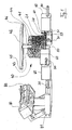
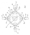
- Fig. 1 shows the mold according to the invention, in which a slider 80 is shown in the removal position of the mold according to the invention.
- a cam 20 By rotation of a cam 20 is a translational displacement of the push rods 30 and connected to these sliders 80. Just before reaching the end point of the displacement of the push rods 30 via a joint 81, a pivoting of the slider 80, which thereby release the stored in the circumferential lips 82 molding.
- the cam 20 are in the embodiment of the Fig. 1 pin-shaped projections 31 of the push rods 30 in engagement.
- a drive device 40 for a table-like designed lifting element 42 is arranged on the upper side 21 of the cam 20, a drive device 40 for a table-like designed lifting element 42 is arranged.
- the drive device 40 is provided in the form of a crank block 41, wherein a riser 44 is introduced as the circumference following, rising curve on the lifting element 42 facing side 43 of the crank block 41.
- the lifting element 42 has on its underside 45 on a pin 46 which runs on the riser 44. As a result, a displacement of the lifting element 42 is achieved perpendicular to the cam 20 and the crank block 41.
- the cam 20 and the drive device 40 are mounted together on a centrally disposed shaft 50 through which both elements are driven.
- the drive is effected by an electric motor arranged at the lower end of the shaft (not shown).
- the rotation of the shaft 50 by about 160 ° clockwise causes in the embodiment of Fig. 1 a displacement of the push rods 30 and thus the slider 80, (in Fig. 1 For reasons of clarity, only one of these slides 80 is shown) to the outside, and thus into the removal position of the molding tool.
- an upward movement of the lifting element 42 By movement of the lifting element 42, the breaking away and lifting of the mold cavity stored in the mold part takes place, the removal of which can be done quickly and easily after completion of the displacement of the lifting element 42.
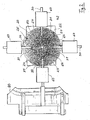
- Fig. 2 shows the embodiment of the control device according to the invention Fig. 1 in bottom view.
- the slides 80 of which in Fig. 2 only one is shown, are in the working position, ie the mold is prepared for receiving a new molding.
- the cam 20 has on its underside 22 via spirally cut into the cam 20 grooves 24, which form a slotted guide 25.
- the pin-shaped projections 31 of the push rods 30 are located on the shaft 50 nearest point, ie furthest to the edge 23 of the cam 20. About the pin-shaped projections 31 thus also the push rods 30 and with this the hinged thereto slide 80 to the center 26th the cam 20 moves towards.
- a rotation of the cam 20 by about 160 ° causes a mediated by the slide guide 25 displacement of the pin-shaped projections 31 in the grooves 24. These move spirally, ie with decreasing, radial distance to the edge 23 of the cam 20 in the groove 24, whereby a translational movement of the push rods 30 and the hinged thereto slider 80 takes place and the removal position of the mold is taken.
- the guide blocks 60 have a tunnel guide for receiving the push rods 30.
- Fig. 2 can be seen also the table-shaped lifting element 40, which is moved with rotation of the cam 20 perpendicularly away from this, thereby breaking off a mold cavity located in the mold part from the mold half and raises the worker or the removal device.
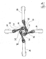
- Fig. 3a shows a further preferred embodiment of the control device according to the invention.
- a central of the shaft 50th penetrated disc 70 is provided which has perpendicular to each other, projecting pins 71.
- an end 75 is mounted in each case a link 72, whose opposite end 76 is articulated to the push rod 30.
- the push rod 30 is in the embodiment of Fig. 3a designed strip-shaped, their leadership is carried out accordingly in a rail 61 which engages around the push rod 30.
- Fig. 3b shows the control device Fig. 3a
- the disc 70 is shown rotated by 90 ° clockwise.
- the attached to the pins 71 link 72 were from the in Fig. 3a shown starting position, which is synonymous with the removal position of the mold, adjusted to the working position.
- This position change is effected by pivoting the link 72, whereby the distance between the push rods 30 and the disk center 73 is shortened and the slide 80 (see. Fig. 1 ) are moved accordingly.
- the slide 80 By reversing the direction of rotation of the drive and subsequent rotation of the disc 70 by 90 ° counterclockwise an opposite pivoting of the handlebar 72 and connected thereto, a displacement of the push rods 30 from the disk center 73 away. Due to the increased distance between the disk center point 73 and push rods 30, the slide 80 are also moved to the outside, away from the disk 70, in the removal position of the mold.
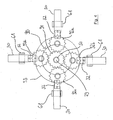
- a further preferred embodiment of the control device according to the invention in the manner of a planetary gear 90 is shown.
- the control device according to the invention has a guide pulley 93 arranged around the sun gear 91 for the planet gears 92a to 92d.
- the band-shaped push rods 30 are extended by hinged thereto, limited pivotable tabs 32 to the disk center 73 out.
- the push rods 30 are also in the embodiment of Fig.
- the control device is designed to be rotatable only in one direction and accordingly has a drive device 40 with a correspondingly adjusted riser 44 (see. Fig. 1 ).
- Fig. 5 also shows the bottom view of another embodiment of the control device according to the invention.
- a disc 70 is provided on a shaft 50 to which a concentrically arranged sun gear 91 is fixedly connected.
- the sun gear 91 drives a planetary gear 92a via a revolving belt 94.
- On the driven planetary gear 92a is eccentrically hinged to a tab 32 which is in engagement with the push rod 30.
- the push rod 30 is strip-shaped in the exemplary embodiment and is guided in a rail 61 to prevent bending occurring during actuation of the push rod 30 and to ensure their uniform, translational movement.
- a roller is mounted, in which a belt drive 95 is guided, which drives the other planet gears 92b to 92d.
- Each of the planet gears 92b to 92d has an eccentrically hinged tab 32 in extension of the push rod 30.
- the rotation of the sun gear 91 thus results in a rotation of the planetary gears 92a to 92d and thereby, depending on the achieved position of the planetary gears 92a to 92d a shortening or lengthening of the distance between the push rod 30 and the disk center 73 and associated therewith a displacement of the slider 80 (see , Fig. 1 ) in the removal or working position of the mold.
Landscapes
- Engineering & Computer Science (AREA)
- Mechanical Engineering (AREA)
- Manufacturing & Machinery (AREA)
- Moulds For Moulding Plastics Or The Like (AREA)
Priority Applications (1)
| Application Number | Priority Date | Filing Date | Title |
|---|---|---|---|
| PL07012887T PL1878552T3 (pl) | 2006-07-11 | 2007-07-02 | Narzędzie kształtowe |
Applications Claiming Priority (1)
| Application Number | Priority Date | Filing Date | Title |
|---|---|---|---|
| DE200620010761 DE202006010761U1 (de) | 2006-07-11 | 2006-07-11 | Formwerkzeug |
Publications (2)
| Publication Number | Publication Date |
|---|---|
| EP1878552A1 EP1878552A1 (de) | 2008-01-16 |
| EP1878552B1 true EP1878552B1 (de) | 2018-11-07 |
Family
ID=38336388
Family Applications (1)
| Application Number | Title | Priority Date | Filing Date |
|---|---|---|---|
| EP07012887.1A Not-in-force EP1878552B1 (de) | 2006-07-11 | 2007-07-02 | Formwerkzeug |
Country Status (5)
| Country | Link |
|---|---|
| EP (1) | EP1878552B1 (pl) |
| DE (1) | DE202006010761U1 (pl) |
| ES (1) | ES2696973T3 (pl) |
| HU (1) | HUE042936T2 (pl) |
| PL (1) | PL1878552T3 (pl) |
Cited By (1)
| Publication number | Priority date | Publication date | Assignee | Title |
|---|---|---|---|---|
| DE102021114436A1 (de) | 2021-06-04 | 2022-12-08 | FKT Formenbau und Kunststofftechnik GmbH | Entformungsbaugruppe für Spritzgießwerkzeuge |
Families Citing this family (1)
| Publication number | Priority date | Publication date | Assignee | Title |
|---|---|---|---|---|
| CN107953501B (zh) * | 2017-10-17 | 2023-10-20 | 福建鸿龙机械有限公司 | 一种转盘式eva鞋底二次发泡成型机及其成型方法 |
Family Cites Families (8)
| Publication number | Priority date | Publication date | Assignee | Title |
|---|---|---|---|---|
| DE2410446A1 (de) * | 1973-03-08 | 1974-09-19 | Jens Ove Nielsen | Auswerfvorrichtung fuer den formenteil einer giessmaschine, insbesondere einer kunststoff-spritzgiessmaschine |
| AU8212075A (en) * | 1975-06-13 | 1976-12-16 | Radial Pneus Australasia Pty L | Tyre vulcanising machine |
| JPS5937215B2 (ja) * | 1981-11-17 | 1984-09-08 | ホンダエンジニアリング株式会社 | 合成樹脂成形金型 |
| EP0354481B1 (en) * | 1988-08-09 | 1995-11-29 | Asahi Glass Company Ltd. | Method of preparing window glass with a gasket and a shaping mold for preparing such window glass |
| US6123535A (en) * | 1996-08-02 | 2000-09-26 | Libbey-Owens-Ford Co. | Molding apparatus for encapsulating a part |
| DE69910180T3 (de) * | 1999-05-24 | 2007-10-18 | Pilkington Italia S.P.A. | Anformen eines elastomerischen Profiles an eine Fensterscheibe |
| DE10064745A1 (de) * | 2000-12-22 | 2002-07-11 | Webasto Vehicle Sys Int Gmbh | Formwerkzeug und Verfahren zum randseitigen Anformen eines profilierten mehrseitigen Kunststoffrahmenteils an einen plattenförmigen Gegenstand |
| DE202005002900U1 (de) * | 2005-02-21 | 2005-06-02 | Bbg Gmbh & Co. Kg | Werkzeug |
-
2006
- 2006-07-11 DE DE200620010761 patent/DE202006010761U1/de not_active Expired - Lifetime
-
2007
- 2007-07-02 HU HUE07012887A patent/HUE042936T2/hu unknown
- 2007-07-02 EP EP07012887.1A patent/EP1878552B1/de not_active Not-in-force
- 2007-07-02 ES ES07012887T patent/ES2696973T3/es active Active
- 2007-07-02 PL PL07012887T patent/PL1878552T3/pl unknown
Non-Patent Citations (1)
| Title |
|---|
| None * |
Cited By (1)
| Publication number | Priority date | Publication date | Assignee | Title |
|---|---|---|---|---|
| DE102021114436A1 (de) | 2021-06-04 | 2022-12-08 | FKT Formenbau und Kunststofftechnik GmbH | Entformungsbaugruppe für Spritzgießwerkzeuge |
Also Published As
| Publication number | Publication date |
|---|---|
| HUE042936T2 (hu) | 2019-07-29 |
| DE202006010761U1 (de) | 2007-08-09 |
| PL1878552T3 (pl) | 2019-06-28 |
| ES2696973T3 (es) | 2019-01-21 |
| EP1878552A1 (de) | 2008-01-16 |
Similar Documents
| Publication | Publication Date | Title |
|---|---|---|
| EP2139670B1 (de) | Verfahren und vorrichtung zur herstellung eines kunststoffprofils | |
| DE2550824C2 (de) | Karussell-Formmaschine | |
| DE102014116087B4 (de) | Gekoppelte Blasformvorrichtung einer drehbaren Blasmaschine | |
| DE2146245B2 (de) | Formwerkzeuge, insbesondere zum Herstellen von Formungen aus Polyurethan | |
| DE102010004781A1 (de) | Trenn- und Abisoliereinrichtung für eine Kabelverarbeitungsmaschine | |
| EP3708328B1 (de) | Werkzeug zum spritzgiessen von kunststoff-formteilen und verfahren zum bewegen eines schiebers einer werkzeughälfte des werkzeugs | |
| EP2523795B1 (de) | Kniehebel-schliesseinheit | |
| EP1878552B1 (de) | Formwerkzeug | |
| EP1621316A1 (de) | Spritzgiessform zum Herstellen von Fittings | |
| EP1162633A1 (de) | Verfahren zur Herstellung von Drilleitern | |
| EP2110220A2 (de) | Vorrichtung zur Herstellung von Formteilen, insbesondere von Schaumformteilen | |
| EP1454783A1 (de) | Lamellen-Fahrzeugdach | |
| AT427U1 (de) | Spritzgusseinrichtung fuer kunststoffe | |
| DE10307669B3 (de) | Druckgußmaschine | |
| DE19923849C2 (de) | Formschließeinheit für eine Spritzgießmaschine | |
| DE69810378T2 (de) | Spritzgiessvorrichtung für Hohlgegenstände wie zum Beispiel Rohrverbindungen | |
| DE102006046862B3 (de) | Verfahren und Stellkrafterzeuger zur Bedienung von Montageplattformen | |
| WO2002057062A1 (de) | Auswerfvorrichtung für eine formmaschine | |
| WO2007065551A1 (de) | Antriebsvorrichtung für ein schiebetor und verfahren zu dessen montage | |
| EP1623811B1 (de) | Spritzgusswerkzeug zur Herstellung von Kunststoffteilen, insbesondere derartiges Werkzeug zum Herstellen von zwei Kunststoffleisten verbindenden Spritzguss-Eckverbindungsteilen | |
| DE2656217C2 (de) | Kurvengetriebe zum Antrieb von Arbeitsstationen einer Verpackungsmaschine | |
| DE2428631A1 (de) | Verfahren und maschine zum kontinuierlichen automatischen herstellen von lichterketten | |
| DE102014225165A1 (de) | Spritzgießmaschine mit einer Schließeinheit | |
| EP3199261A2 (de) | Vorrichtung zur herstellung von bewehrungen | |
| DE10121230C1 (de) | Werkzeug zum Mehrkomponenten-Spritzgießen von Kunststoff-Spritzteilen |
Legal Events
| Date | Code | Title | Description |
|---|---|---|---|
| PUAI | Public reference made under article 153(3) epc to a published international application that has entered the european phase |
Free format text: ORIGINAL CODE: 0009012 |
|
| AK | Designated contracting states |
Kind code of ref document: A1 Designated state(s): AT BE BG CH CY CZ DE DK EE ES FI FR GB GR HU IE IS IT LI LT LU LV MC MT NL PL PT RO SE SI SK TR |
|
| AX | Request for extension of the european patent |
Extension state: AL BA HR MK YU |
|
| 17P | Request for examination filed |
Effective date: 20080616 |
|
| 17Q | First examination report despatched |
Effective date: 20080717 |
|
| AKX | Designation fees paid |
Designated state(s): AT BE BG CH CY CZ DE DK EE ES FI FR GB GR HU IE IS IT LI LT LU LV MC MT NL PL PT RO SE SI SK TR |
|
| RIN1 | Information on inventor provided before grant (corrected) |
Inventor name: SATZGER BERNHARD Inventor name: LUDWIG, THOMAS Inventor name: BRANDNER, HANS |
|
| STAA | Information on the status of an ep patent application or granted ep patent |
Free format text: STATUS: EXAMINATION IS IN PROGRESS |
|
| GRAP | Despatch of communication of intention to grant a patent |
Free format text: ORIGINAL CODE: EPIDOSNIGR1 |
|
| STAA | Information on the status of an ep patent application or granted ep patent |
Free format text: STATUS: GRANT OF PATENT IS INTENDED |
|
| INTG | Intention to grant announced |
Effective date: 20171213 |
|
| RIN1 | Information on inventor provided before grant (corrected) |
Inventor name: LUDWIG, THOMAS Inventor name: SATZGER, BERNHARD Inventor name: BRANDNER, HANS |
|
| GRAJ | Information related to disapproval of communication of intention to grant by the applicant or resumption of examination proceedings by the epo deleted |
Free format text: ORIGINAL CODE: EPIDOSDIGR1 |
|
| STAA | Information on the status of an ep patent application or granted ep patent |
Free format text: STATUS: EXAMINATION IS IN PROGRESS |
|
| GRAP | Despatch of communication of intention to grant a patent |
Free format text: ORIGINAL CODE: EPIDOSNIGR1 |
|
| STAA | Information on the status of an ep patent application or granted ep patent |
Free format text: STATUS: GRANT OF PATENT IS INTENDED |
|
| INTC | Intention to grant announced (deleted) | ||
| INTG | Intention to grant announced |
Effective date: 20180515 |
|
| GRAS | Grant fee paid |
Free format text: ORIGINAL CODE: EPIDOSNIGR3 |
|
| GRAA | (expected) grant |
Free format text: ORIGINAL CODE: 0009210 |
|
| STAA | Information on the status of an ep patent application or granted ep patent |
Free format text: STATUS: THE PATENT HAS BEEN GRANTED |
|
| AK | Designated contracting states |
Kind code of ref document: B1 Designated state(s): AT BE BG CH CY CZ DE DK EE ES FI FR GB GR HU IE IS IT LI LT LU LV MC MT NL PL PT RO SE SI SK TR |
|
| RAP1 | Party data changed (applicant data changed or rights of an application transferred) |
Owner name: BBG GMBH & CO. KG |
|
| REG | Reference to a national code |
Ref country code: GB Ref legal event code: FG4D Free format text: NOT ENGLISH |
|
| REG | Reference to a national code |
Ref country code: CH Ref legal event code: EP Ref country code: AT Ref legal event code: REF Ref document number: 1061524 Country of ref document: AT Kind code of ref document: T Effective date: 20181115 |
|
| REG | Reference to a national code |
Ref country code: IE Ref legal event code: FG4D Free format text: LANGUAGE OF EP DOCUMENT: GERMAN |
|
| REG | Reference to a national code |
Ref country code: DE Ref legal event code: R096 Ref document number: 502007016474 Country of ref document: DE |
|
| REG | Reference to a national code |
Ref country code: ES Ref legal event code: FG2A Ref document number: 2696973 Country of ref document: ES Kind code of ref document: T3 Effective date: 20190121 |
|
| REG | Reference to a national code |
Ref country code: RO Ref legal event code: EPE |
|
| REG | Reference to a national code |
Ref country code: NL Ref legal event code: FP |
|
| REG | Reference to a national code |
Ref country code: LT Ref legal event code: MG4D |
|
| PG25 | Lapsed in a contracting state [announced via postgrant information from national office to epo] |
Ref country code: LV Free format text: LAPSE BECAUSE OF FAILURE TO SUBMIT A TRANSLATION OF THE DESCRIPTION OR TO PAY THE FEE WITHIN THE PRESCRIBED TIME-LIMIT Effective date: 20181107 Ref country code: BG Free format text: LAPSE BECAUSE OF FAILURE TO SUBMIT A TRANSLATION OF THE DESCRIPTION OR TO PAY THE FEE WITHIN THE PRESCRIBED TIME-LIMIT Effective date: 20190207 Ref country code: LT Free format text: LAPSE BECAUSE OF FAILURE TO SUBMIT A TRANSLATION OF THE DESCRIPTION OR TO PAY THE FEE WITHIN THE PRESCRIBED TIME-LIMIT Effective date: 20181107 Ref country code: IS Free format text: LAPSE BECAUSE OF FAILURE TO SUBMIT A TRANSLATION OF THE DESCRIPTION OR TO PAY THE FEE WITHIN THE PRESCRIBED TIME-LIMIT Effective date: 20190307 Ref country code: FI Free format text: LAPSE BECAUSE OF FAILURE TO SUBMIT A TRANSLATION OF THE DESCRIPTION OR TO PAY THE FEE WITHIN THE PRESCRIBED TIME-LIMIT Effective date: 20181107 |
|
| PG25 | Lapsed in a contracting state [announced via postgrant information from national office to epo] |
Ref country code: SE Free format text: LAPSE BECAUSE OF FAILURE TO SUBMIT A TRANSLATION OF THE DESCRIPTION OR TO PAY THE FEE WITHIN THE PRESCRIBED TIME-LIMIT Effective date: 20181107 Ref country code: PT Free format text: LAPSE BECAUSE OF FAILURE TO SUBMIT A TRANSLATION OF THE DESCRIPTION OR TO PAY THE FEE WITHIN THE PRESCRIBED TIME-LIMIT Effective date: 20190307 Ref country code: GR Free format text: LAPSE BECAUSE OF FAILURE TO SUBMIT A TRANSLATION OF THE DESCRIPTION OR TO PAY THE FEE WITHIN THE PRESCRIBED TIME-LIMIT Effective date: 20190208 |
|
| REG | Reference to a national code |
Ref country code: SK Ref legal event code: T3 Ref document number: E 29980 Country of ref document: SK |
|
| REG | Reference to a national code |
Ref country code: HU Ref legal event code: AG4A Ref document number: E042936 Country of ref document: HU |
|
| PG25 | Lapsed in a contracting state [announced via postgrant information from national office to epo] |
Ref country code: DK Free format text: LAPSE BECAUSE OF FAILURE TO SUBMIT A TRANSLATION OF THE DESCRIPTION OR TO PAY THE FEE WITHIN THE PRESCRIBED TIME-LIMIT Effective date: 20181107 |
|
| PGFP | Annual fee paid to national office [announced via postgrant information from national office to epo] |
Ref country code: CZ Payment date: 20190516 Year of fee payment: 13 Ref country code: PL Payment date: 20190527 Year of fee payment: 13 |
|
| REG | Reference to a national code |
Ref country code: DE Ref legal event code: R097 Ref document number: 502007016474 Country of ref document: DE |
|
| PG25 | Lapsed in a contracting state [announced via postgrant information from national office to epo] |
Ref country code: EE Free format text: LAPSE BECAUSE OF FAILURE TO SUBMIT A TRANSLATION OF THE DESCRIPTION OR TO PAY THE FEE WITHIN THE PRESCRIBED TIME-LIMIT Effective date: 20181107 |
|
| PGFP | Annual fee paid to national office [announced via postgrant information from national office to epo] |
Ref country code: FR Payment date: 20190612 Year of fee payment: 13 |
|
| PLBE | No opposition filed within time limit |
Free format text: ORIGINAL CODE: 0009261 |
|
| STAA | Information on the status of an ep patent application or granted ep patent |
Free format text: STATUS: NO OPPOSITION FILED WITHIN TIME LIMIT |
|
| PGFP | Annual fee paid to national office [announced via postgrant information from national office to epo] |
Ref country code: SK Payment date: 20190517 Year of fee payment: 13 |
|
| 26N | No opposition filed |
Effective date: 20190808 |
|
| PG25 | Lapsed in a contracting state [announced via postgrant information from national office to epo] |
Ref country code: SI Free format text: LAPSE BECAUSE OF FAILURE TO SUBMIT A TRANSLATION OF THE DESCRIPTION OR TO PAY THE FEE WITHIN THE PRESCRIBED TIME-LIMIT Effective date: 20181107 |
|
| PGFP | Annual fee paid to national office [announced via postgrant information from national office to epo] |
Ref country code: RO Payment date: 20190701 Year of fee payment: 13 |
|
| PGFP | Annual fee paid to national office [announced via postgrant information from national office to epo] |
Ref country code: GB Payment date: 20190710 Year of fee payment: 13 |
|
| PGFP | Annual fee paid to national office [announced via postgrant information from national office to epo] |
Ref country code: DE Payment date: 20190930 Year of fee payment: 13 |
|
| PG25 | Lapsed in a contracting state [announced via postgrant information from national office to epo] |
Ref country code: MC Free format text: LAPSE BECAUSE OF FAILURE TO SUBMIT A TRANSLATION OF THE DESCRIPTION OR TO PAY THE FEE WITHIN THE PRESCRIBED TIME-LIMIT Effective date: 20181107 |
|
| REG | Reference to a national code |
Ref country code: CH Ref legal event code: PL |
|
| PG25 | Lapsed in a contracting state [announced via postgrant information from national office to epo] |
Ref country code: TR Free format text: LAPSE BECAUSE OF FAILURE TO SUBMIT A TRANSLATION OF THE DESCRIPTION OR TO PAY THE FEE WITHIN THE PRESCRIBED TIME-LIMIT Effective date: 20181107 |
|
| REG | Reference to a national code |
Ref country code: BE Ref legal event code: MM Effective date: 20190731 |
|
| PG25 | Lapsed in a contracting state [announced via postgrant information from national office to epo] |
Ref country code: HU Free format text: LAPSE BECAUSE OF NON-PAYMENT OF DUE FEES Effective date: 20190703 Ref country code: NL Free format text: LAPSE BECAUSE OF NON-PAYMENT OF DUE FEES Effective date: 20190801 |
|
| REG | Reference to a national code |
Ref country code: NL Ref legal event code: MM Effective date: 20190801 |
|
| PG25 | Lapsed in a contracting state [announced via postgrant information from national office to epo] |
Ref country code: CH Free format text: LAPSE BECAUSE OF NON-PAYMENT OF DUE FEES Effective date: 20190731 Ref country code: LU Free format text: LAPSE BECAUSE OF NON-PAYMENT OF DUE FEES Effective date: 20190702 Ref country code: BE Free format text: LAPSE BECAUSE OF NON-PAYMENT OF DUE FEES Effective date: 20190731 Ref country code: LI Free format text: LAPSE BECAUSE OF NON-PAYMENT OF DUE FEES Effective date: 20190731 |
|
| PG25 | Lapsed in a contracting state [announced via postgrant information from national office to epo] |
Ref country code: IE Free format text: LAPSE BECAUSE OF NON-PAYMENT OF DUE FEES Effective date: 20190702 |
|
| PG25 | Lapsed in a contracting state [announced via postgrant information from national office to epo] |
Ref country code: IT Free format text: LAPSE BECAUSE OF NON-PAYMENT OF DUE FEES Effective date: 20190702 |
|
| REG | Reference to a national code |
Ref country code: AT Ref legal event code: MM01 Ref document number: 1061524 Country of ref document: AT Kind code of ref document: T Effective date: 20190702 |
|
| REG | Reference to a national code |
Ref country code: ES Ref legal event code: FD2A Effective date: 20201126 |
|
| PG25 | Lapsed in a contracting state [announced via postgrant information from national office to epo] |
Ref country code: AT Free format text: LAPSE BECAUSE OF NON-PAYMENT OF DUE FEES Effective date: 20190702 |
|
| PG25 | Lapsed in a contracting state [announced via postgrant information from national office to epo] |
Ref country code: CZ Free format text: LAPSE BECAUSE OF NON-PAYMENT OF DUE FEES Effective date: 20200702 Ref country code: ES Free format text: LAPSE BECAUSE OF NON-PAYMENT OF DUE FEES Effective date: 20190703 |
|
| REG | Reference to a national code |
Ref country code: DE Ref legal event code: R119 Ref document number: 502007016474 Country of ref document: DE |
|
| REG | Reference to a national code |
Ref country code: SK Ref legal event code: MM4A Ref document number: E 29980 Country of ref document: SK Effective date: 20200702 |
|
| GBPC | Gb: european patent ceased through non-payment of renewal fee |
Effective date: 20200702 |
|
| PG25 | Lapsed in a contracting state [announced via postgrant information from national office to epo] |
Ref country code: FR Free format text: LAPSE BECAUSE OF NON-PAYMENT OF DUE FEES Effective date: 20200731 Ref country code: GB Free format text: LAPSE BECAUSE OF NON-PAYMENT OF DUE FEES Effective date: 20200702 Ref country code: RO Free format text: LAPSE BECAUSE OF NON-PAYMENT OF DUE FEES Effective date: 20200702 |
|
| PG25 | Lapsed in a contracting state [announced via postgrant information from national office to epo] |
Ref country code: DE Free format text: LAPSE BECAUSE OF NON-PAYMENT OF DUE FEES Effective date: 20210202 Ref country code: CY Free format text: LAPSE BECAUSE OF FAILURE TO SUBMIT A TRANSLATION OF THE DESCRIPTION OR TO PAY THE FEE WITHIN THE PRESCRIBED TIME-LIMIT Effective date: 20181107 |
|
| PG25 | Lapsed in a contracting state [announced via postgrant information from national office to epo] |
Ref country code: SK Free format text: LAPSE BECAUSE OF NON-PAYMENT OF DUE FEES Effective date: 20200702 |
|
| PG25 | Lapsed in a contracting state [announced via postgrant information from national office to epo] |
Ref country code: MT Free format text: LAPSE BECAUSE OF FAILURE TO SUBMIT A TRANSLATION OF THE DESCRIPTION OR TO PAY THE FEE WITHIN THE PRESCRIBED TIME-LIMIT Effective date: 20181107 |
|
| PG25 | Lapsed in a contracting state [announced via postgrant information from national office to epo] |
Ref country code: PL Free format text: LAPSE BECAUSE OF NON-PAYMENT OF DUE FEES Effective date: 20200702 |