EP1876829A1 - Systeme de surveillance de la peripherie d'un vehicule - Google Patents
Systeme de surveillance de la peripherie d'un vehicule Download PDFInfo
- Publication number
- EP1876829A1 EP1876829A1 EP06732264A EP06732264A EP1876829A1 EP 1876829 A1 EP1876829 A1 EP 1876829A1 EP 06732264 A EP06732264 A EP 06732264A EP 06732264 A EP06732264 A EP 06732264A EP 1876829 A1 EP1876829 A1 EP 1876829A1
- Authority
- EP
- European Patent Office
- Prior art keywords
- vehicle
- lighting device
- image
- obstacle
- light
- Prior art date
- Legal status (The legal status is an assumption and is not a legal conclusion. Google has not performed a legal analysis and makes no representation as to the accuracy of the status listed.)
- Withdrawn
Links
- 238000012544 monitoring process Methods 0.000 title claims abstract description 49
- 238000005286 illumination Methods 0.000 claims abstract description 95
- 238000003384 imaging method Methods 0.000 claims abstract description 25
- 230000033001 locomotion Effects 0.000 claims description 19
- 230000002441 reversible effect Effects 0.000 claims description 6
- 230000035945 sensitivity Effects 0.000 claims description 3
- 230000000694 effects Effects 0.000 abstract description 17
- 230000002411 adverse Effects 0.000 abstract description 4
- 238000010586 diagram Methods 0.000 description 28
- 238000009434 installation Methods 0.000 description 28
- 238000001514 detection method Methods 0.000 description 12
- 238000012545 processing Methods 0.000 description 9
- 230000003287 optical effect Effects 0.000 description 4
- 238000003708 edge detection Methods 0.000 description 3
- 238000000034 method Methods 0.000 description 3
- 238000012806 monitoring device Methods 0.000 description 3
- 230000002829 reductive effect Effects 0.000 description 3
- 230000000153 supplemental effect Effects 0.000 description 3
- 238000000605 extraction Methods 0.000 description 2
- 235000021189 garnishes Nutrition 0.000 description 2
- 230000010076 replication Effects 0.000 description 2
- 230000000007 visual effect Effects 0.000 description 2
- 238000013459 approach Methods 0.000 description 1
- 230000004888 barrier function Effects 0.000 description 1
- 230000009286 beneficial effect Effects 0.000 description 1
- 230000000981 bystander Effects 0.000 description 1
- 238000010276 construction Methods 0.000 description 1
- 230000003247 decreasing effect Effects 0.000 description 1
- 230000002349 favourable effect Effects 0.000 description 1
- 230000003760 hair shine Effects 0.000 description 1
- 239000000463 material Substances 0.000 description 1
- 238000012986 modification Methods 0.000 description 1
- 230000004048 modification Effects 0.000 description 1
- 239000007787 solid Substances 0.000 description 1
- 238000012795 verification Methods 0.000 description 1
- 230000003313 weakening effect Effects 0.000 description 1
Images


Classifications
-
- B—PERFORMING OPERATIONS; TRANSPORTING
- B60—VEHICLES IN GENERAL
- B60Q—ARRANGEMENT OF SIGNALLING OR LIGHTING DEVICES, THE MOUNTING OR SUPPORTING THEREOF OR CIRCUITS THEREFOR, FOR VEHICLES IN GENERAL
- B60Q9/00—Arrangement or adaptation of signal devices not provided for in one of main groups B60Q1/00 - B60Q7/00, e.g. haptic signalling
- B60Q9/002—Arrangement or adaptation of signal devices not provided for in one of main groups B60Q1/00 - B60Q7/00, e.g. haptic signalling for parking purposes, e.g. for warning the driver that his vehicle has contacted or is about to contact an obstacle
- B60Q9/004—Arrangement or adaptation of signal devices not provided for in one of main groups B60Q1/00 - B60Q7/00, e.g. haptic signalling for parking purposes, e.g. for warning the driver that his vehicle has contacted or is about to contact an obstacle using wave sensors
-
- B—PERFORMING OPERATIONS; TRANSPORTING
- B60—VEHICLES IN GENERAL
- B60R—VEHICLES, VEHICLE FITTINGS, OR VEHICLE PARTS, NOT OTHERWISE PROVIDED FOR
- B60R1/00—Optical viewing arrangements; Real-time viewing arrangements for drivers or passengers using optical image capturing systems, e.g. cameras or video systems specially adapted for use in or on vehicles
- B60R1/20—Real-time viewing arrangements for drivers or passengers using optical image capturing systems, e.g. cameras or video systems specially adapted for use in or on vehicles
- B60R1/22—Real-time viewing arrangements for drivers or passengers using optical image capturing systems, e.g. cameras or video systems specially adapted for use in or on vehicles for viewing an area outside the vehicle, e.g. the exterior of the vehicle
- B60R1/23—Real-time viewing arrangements for drivers or passengers using optical image capturing systems, e.g. cameras or video systems specially adapted for use in or on vehicles for viewing an area outside the vehicle, e.g. the exterior of the vehicle with a predetermined field of view
- B60R1/26—Real-time viewing arrangements for drivers or passengers using optical image capturing systems, e.g. cameras or video systems specially adapted for use in or on vehicles for viewing an area outside the vehicle, e.g. the exterior of the vehicle with a predetermined field of view to the rear of the vehicle
-
- B—PERFORMING OPERATIONS; TRANSPORTING
- B60—VEHICLES IN GENERAL
- B60R—VEHICLES, VEHICLE FITTINGS, OR VEHICLE PARTS, NOT OTHERWISE PROVIDED FOR
- B60R1/00—Optical viewing arrangements; Real-time viewing arrangements for drivers or passengers using optical image capturing systems, e.g. cameras or video systems specially adapted for use in or on vehicles
- B60R1/20—Real-time viewing arrangements for drivers or passengers using optical image capturing systems, e.g. cameras or video systems specially adapted for use in or on vehicles
- B60R1/30—Real-time viewing arrangements for drivers or passengers using optical image capturing systems, e.g. cameras or video systems specially adapted for use in or on vehicles providing vision in the non-visible spectrum, e.g. night or infrared vision
-
- B—PERFORMING OPERATIONS; TRANSPORTING
- B60—VEHICLES IN GENERAL
- B60R—VEHICLES, VEHICLE FITTINGS, OR VEHICLE PARTS, NOT OTHERWISE PROVIDED FOR
- B60R11/00—Arrangements for holding or mounting articles, not otherwise provided for
- B60R11/04—Mounting of cameras operative during drive; Arrangement of controls thereof relative to the vehicle
-
- G—PHYSICS
- G06—COMPUTING; CALCULATING OR COUNTING
- G06V—IMAGE OR VIDEO RECOGNITION OR UNDERSTANDING
- G06V10/00—Arrangements for image or video recognition or understanding
- G06V10/10—Image acquisition
- G06V10/12—Details of acquisition arrangements; Constructional details thereof
- G06V10/14—Optical characteristics of the device performing the acquisition or on the illumination arrangements
- G06V10/145—Illumination specially adapted for pattern recognition, e.g. using gratings
-
- G—PHYSICS
- G06—COMPUTING; CALCULATING OR COUNTING
- G06V—IMAGE OR VIDEO RECOGNITION OR UNDERSTANDING
- G06V20/00—Scenes; Scene-specific elements
- G06V20/50—Context or environment of the image
- G06V20/56—Context or environment of the image exterior to a vehicle by using sensors mounted on the vehicle
- G06V20/58—Recognition of moving objects or obstacles, e.g. vehicles or pedestrians; Recognition of traffic objects, e.g. traffic signs, traffic lights or roads
- G06V20/586—Recognition of moving objects or obstacles, e.g. vehicles or pedestrians; Recognition of traffic objects, e.g. traffic signs, traffic lights or roads of parking space
-
- H—ELECTRICITY
- H04—ELECTRIC COMMUNICATION TECHNIQUE
- H04N—PICTORIAL COMMUNICATION, e.g. TELEVISION
- H04N7/00—Television systems
- H04N7/18—Closed-circuit television [CCTV] systems, i.e. systems in which the video signal is not broadcast
-
- B—PERFORMING OPERATIONS; TRANSPORTING
- B60—VEHICLES IN GENERAL
- B60R—VEHICLES, VEHICLE FITTINGS, OR VEHICLE PARTS, NOT OTHERWISE PROVIDED FOR
- B60R2300/00—Details of viewing arrangements using cameras and displays, specially adapted for use in a vehicle
- B60R2300/10—Details of viewing arrangements using cameras and displays, specially adapted for use in a vehicle characterised by the type of camera system used
- B60R2300/103—Details of viewing arrangements using cameras and displays, specially adapted for use in a vehicle characterised by the type of camera system used using camera systems provided with artificial illumination device, e.g. IR light source
-
- B—PERFORMING OPERATIONS; TRANSPORTING
- B60—VEHICLES IN GENERAL
- B60R—VEHICLES, VEHICLE FITTINGS, OR VEHICLE PARTS, NOT OTHERWISE PROVIDED FOR
- B60R2300/00—Details of viewing arrangements using cameras and displays, specially adapted for use in a vehicle
- B60R2300/30—Details of viewing arrangements using cameras and displays, specially adapted for use in a vehicle characterised by the type of image processing
- B60R2300/302—Details of viewing arrangements using cameras and displays, specially adapted for use in a vehicle characterised by the type of image processing combining image information with GPS information or vehicle data, e.g. vehicle speed, gyro, steering angle data
-
- B—PERFORMING OPERATIONS; TRANSPORTING
- B60—VEHICLES IN GENERAL
- B60R—VEHICLES, VEHICLE FITTINGS, OR VEHICLE PARTS, NOT OTHERWISE PROVIDED FOR
- B60R2300/00—Details of viewing arrangements using cameras and displays, specially adapted for use in a vehicle
- B60R2300/80—Details of viewing arrangements using cameras and displays, specially adapted for use in a vehicle characterised by the intended use of the viewing arrangement
- B60R2300/8053—Details of viewing arrangements using cameras and displays, specially adapted for use in a vehicle characterised by the intended use of the viewing arrangement for bad weather conditions or night vision
-
- B—PERFORMING OPERATIONS; TRANSPORTING
- B60—VEHICLES IN GENERAL
- B60R—VEHICLES, VEHICLE FITTINGS, OR VEHICLE PARTS, NOT OTHERWISE PROVIDED FOR
- B60R2300/00—Details of viewing arrangements using cameras and displays, specially adapted for use in a vehicle
- B60R2300/80—Details of viewing arrangements using cameras and displays, specially adapted for use in a vehicle characterised by the intended use of the viewing arrangement
- B60R2300/806—Details of viewing arrangements using cameras and displays, specially adapted for use in a vehicle characterised by the intended use of the viewing arrangement for aiding parking
-
- B—PERFORMING OPERATIONS; TRANSPORTING
- B60—VEHICLES IN GENERAL
- B60R—VEHICLES, VEHICLE FITTINGS, OR VEHICLE PARTS, NOT OTHERWISE PROVIDED FOR
- B60R2300/00—Details of viewing arrangements using cameras and displays, specially adapted for use in a vehicle
- B60R2300/80—Details of viewing arrangements using cameras and displays, specially adapted for use in a vehicle characterised by the intended use of the viewing arrangement
- B60R2300/8093—Details of viewing arrangements using cameras and displays, specially adapted for use in a vehicle characterised by the intended use of the viewing arrangement for obstacle warning
Definitions
- the present invention relates to a vehicle vicinity monitoring system for providing vehicle occupants with information related to obstacles existing in the vicinity of a vehicle.
- Patent Document 1 An invention for a vicinity monitoring device used as such a vehicle vicinity monitoring system is described in Patent Document 1, listed below. That vicinity monitoring device monitors the environment in the vicinity of a moving object such as a vehicle, and displays an image of a visual field from a desired location.
- Patent Document 1 gives an example of a device for monitoring the vicinity of a vehicle, and appropriately displaying objects that form an obstacle to parking. That device utilizes a camera on the rear of the vehicle for capturing images. Additionally, that device performs graphics calculations and parking guidance calculation operations utilizing a CPU, based on information such as obtained images, vehicle travel speed, steering state, and turning state. The results of those calculations are displayed on a monitor within the vehicle.
- Patent Document 1 JP 2005-20558 A (Paragraphs 20 through 29, FIG. 5)
- the camera mounted on the rear of the vehicle can obtain a good image during the day or in other conditions where the surroundings are well lit.
- the resulting image undergoes a variety of image processing procedures.
- border enhancement or edge detection can be performed, so as to clarify the boundary between for example the road surface and obstacles such as vehicles parked in the vicinity of the vehicle.
- the obtained image will have sufficient contrast such that border enhancement or edge detection can be performed.
- the vehicle vicinity monitoring system pertaining to the present invention uses an image-capturing device to photograph a scene in the vicinity of the vehicle, and uses a notification device to provide vehicle occupants with information concerning obstacles in the vicinity of the vehicle.
- the system is constituted as described hereunder.
- the vehicle vicinity monitoring device is characterized in that a primary lighting device, or a secondary lighting device, or both the primary lighting device and the secondary lighting device, are provided to the vehicle.
- the primary lighting device is a lighting device wherein the illumination of the illumination device provided to the vehicle directs light on an obstacle shadow created within the imaging field of the image-capturing device, whereby the shadow is minimized and the border of the obstacle is made to stand out.
- the secondary lighting device is a lighting device for projecting light in a prescribed pattern within the imaging field of the image-capturing device for the purpose of confirming the existence of the obstacle.
- the position of the obstacle to be detected is unknown.
- the installation positions of the image-capturing device and the illumination device for shining light on the obstacle using illumination are known. Therefore, in the event that an obstacle exists, it is possible to ascertain in advance the relationship between the obstacle position and the shadow created by the illumination from the illumination device, as well as the position of the shadow within the imaging field. It is therefore possible to determine in advance a direction (the prescribed direction) that will include the boundary portion between the shadow (background) and the obstacle. Light can then be directed so as to encompass the prescribed direction, thereby lightening the shadows encompassed by the imaging field, and causing the border of the obstacles to stand out. The border portion will change depending upon the position where the obstacle exists.
- the illuminating light that is directed must therefore be of a certain width so as to encompass the prescribed direction.
- the obstacle is far away from the vehicle, there is little immediacy for the border of the obstacle to be extracted. In other words, it is acceptable for the boundary between the obstacle and the background to be indistinct. Therefore, when the object is presumed to be located nearby, it will be sufficient as a minimum if a direction that will encompass the boundary portion when illuminated is selected as the prescribed direction.
- the primary lighting device can thus be positioned so as to illuminate an area that will encompass the boundary portion between an obstacle of unknown location and existence, as well as the background. As a result it is possible to remove the effects of the shadow and satisfactorily extract the border of the obstacle, while also providing vehicle occupants with information concerning the obstacle via a monitor or other device within the vehicle.
- the primary lighting device described above or a secondary lighting device as described below, or a combination of both the primary and secondary lighting systems, are provided to the vehicle.
- the secondary lighting device is a lighting device for projecting light containing a prescribed pattern into the imaging field of the image-capturing device. Light reflected from an obstacle that has been illuminated with the light having a specific pattern enters the image-capturing device, and a pattern image applicable to the prescribed pattern is recreated in the captured image. Light that contains a specified pattern and has been reflected from a ground surface (road surface) or wall surface, on the other hand, will be formed as a captured image that is different from the pattern image formed by reflection from an obstacle.
- the vehicle vicinity monitoring system pertaining to the present invention is further characterized in that a direction that is the same as the angle of vision from the image-capturing device to the obstacle is used as a reference, and the primary lighting device directs light outward from the vehicle relative to that direction.
- the primary lighting device may be able to illuminate the boundary area between an obstacle and the background. Therefore, directing light at least in the same direction as the angle of vision from the image-capturing device to the obstacle enables the obstacle shadow created by the illuminated lighting device to be made lighter within the imaging field. In other words, shadows of obstacles can be satisfactorily minimized if the lighting device directs light outward from the vehicle in the width direction, using the same direction as the angle of vision as a reference.
- the vehicle vicinity monitoring system pertaining to the present invention is further characterized in that a plurality primary lighting devices is provided, and the lighting devices direct light in prescribed directions to the left and right of the vehicle in the width direction thereof.
- the vehicle vicinity monitoring system pertaining to the present invention is further characterized in being provided with movement state detecting means for detecting the direction in which the vehicle is traveling, and in that the primary lighting devices direct light according to the results of the detection obtained from the movement state detecting means.
- light can be directed from the primary lighting device only when so required. Should the primary lighting device constantly emit light, then when vehicle vicinity monitoring is not required in that direction, light will be unnecessarily emitted, which is also undesirable from a standpoint of lowering energy usage by the vehicle.
- wasteful illumination is provided in directions in which vehicle vicinity monitoring is not required, as in the case above. It is possible to minimize the amount of power wasted through wasteful illumination by using the movement state detecting means for determining the direction in which the vehicle is traveling, and using the detection results to illuminate the side requiring vicinity monitoring.
- the vehicle vicinity monitoring system pertaining to the present invention is further characterized in that the image-capturing device is provided to a central area of the vehicle along the width direction, that the primary lighting devices are provided to the left and right sides of the vehicle along the width direction, and that the primary lighting devices collectively direct light on at least the imaging field at their own respective intensity level.
- a wide-angle primary lighting device which is capable of collectively directing light on the imaging field of the image-capturing device, directs light in the imaging field.
- the boundary area between obstacles and the background is contained within this field of illumination, allowing for lessening of the shadow cast by the illumination device.
- the contrast between an obstacle and the background is accordingly increased.
- the individual illumination intensity levels of each of the primary lighting devices are independent. Therefore, for example, should the direction of vehicle travel be used to determine a side of the vehicle for which vicinity monitoring is necessary (a side either to the right or left of the direction of travel), the illumination intensity of the primary lighting device can be controlled.
- the vehicle vicinity monitoring system pertaining to the present invention is also characterized in that the primary lighting devices provided to the right and the left of the vehicle in the width direction switch between illumination intensities so that one of the illumination intensities is stronger and the other illumination intensity is weaker.
- image processing can make an effective distinction between an obstacle in the form of a real object, and the shadow of that object.
- light from a primary lighting device provided to the side opposite the side on which the obstacle is located is able to reach away from the vehicle in the width direction toward the shadow of the obstacle. Accordingly, the effect of the shadow can be adequately eliminated in regard to the viewing angle of the image-capturing device.
- light from a lighting device that is provided to the same side as the obstacle will form a shadow of the obstacle within the imaging field of the image-capturing device, as occurs with the illumination from an illumination device. Therefore, the image-capturing device will obtain differing images, depending on the light from each of the two primary lighting devices.
- the illumination intensity of the primary lighting devices may be switched according to the detection results of the movement state detecting means as described above. By doing so, it is possible for the primary lighting device to direct light only when so required, and only in the direction required. As a result, it is possible to lessen the amount of power wasted through unneeded illumination, and to conserve energy.
- the vehicle vicinity monitoring system pertaining to the present invention is also characterized in that the secondary lighting device directs light in a prescribed direction on at least the left or right of the vehicle in the width direction.
- the position of the obstacle that is the target of detection, including whether the obstacle exists or not, is unknown.
- the installation positions of the illumination device that shines light on the obstacle when illuminated and the position of the image-capturing device are known. Therefore, in the event that an obstacle exists, it is possible to ascertain in advance the relationship between the obstacle position and the shadow created by the illumination from the illumination device, as well as the position of the shadow within the imaging field. It is therefore possible to determine in advance a direction (the prescribed direction) that will include the boundary portion between the shadow (background) and the obstacle. Light can then be directed in the prescribed direction, and thereby projected on both the obstacle and the background.
- the image-capturing device can obtain a reconstructed image of the specified pattern that shows discontinuities at the boundary area, as described above. As a result, it becomes possible to provide a system capable of extracting the boundary of the obstacle without any adverse effects caused by the obstacle shadow, even when the vicinity of the vehicle is under darker conditions than in daytime.
- the boundary portion will change depending upon the position where the obstacle exists. It is therefore necessary for the illuminating light directed in the prescribed direction to have a certain amount of breadth. On the other hand, if the obstacle is far away from the vehicle, there is little immediacy in the need to extract the border of the obstacle. In other words, it is acceptable for the boundary between the obstacle and the background to remain indistinct. Therefore, when the object is presumed to be located nearby, it will be sufficient as a minimum if a direction that will encompass the boundary portion when illuminated is selected as the prescribed direction.
- the primary lighting device can thus be positioned so as to illuminate an area that will encompass the boundary portion between an obstacle of unknown location and existence, as well as the background.
- the above conditions would be fulfilled by having the center of the optical axis be the same direction as the viewing angle from the image-capturing device to the obstacle, and projecting light of a certain width in that direction. Therefore, one embodiment that would yield a favorable projection would involve providing the secondary lighting device in the same position as the image-capturing device in the width direction of the vehicle, and projecting from that position in at least one of the prescribed directions (the viewing angle direction) on the left or right of the vehicle.
- Illumination from the secondary lighting device is reflected by obstacles, and a pattern image according to the prescribed pattern can be created by using the image-capturing device to capture that reflected light. Therefore, ideally, the patterned light should be projected at an angle such that the patterned illuminated light is reflected directly by the obstacle. In other words, the patterned light is projected at an angle such that light is reflected directly back into the image-capturing device mounted on the vehicle. For example, in the case that the obstacle is located behind the vehicle, projecting in such a manner is possible. However, in a case where the obstacle is located to the side of the vehicle, it would be necessary to project light in the prescribed pattern from far behind the vehicle, which is not practical.
- the secondary lighting device be provided so as to project in a direction away from the vehicle relative to the direction that is the same as the viewing angle from the image-capturing device to the obstacle.
- One embodiment would be for the image-capturing device to be provided to a center area, and to project from the side opposite the side of the vehicle along the width direction on which the obstacle is present. Doing so would allow for a deeper angle relative to the obstacle; i.e., an angle in a direction that is close to mirror-reflected light with regard to the viewing angle from the image-capturing device to the obstacle.
- the secondary lighting device illuminates at a minimum the side that is not easily seen by the driver.
- multiple secondary lighting devices can also be made capable of projecting only when required, and only in the direction required. Should the secondary lighting device project constantly, it would project unnecessarily in directions where vicinity monitoring is not required, which is also undesirable from a standpoint of lowering vehicle energy usage.
- the vehicle vicinity monitoring system related to the present invention is also characterized in that the prescribed pattern is one of a straight-line slit pattern, a lattice pattern or a dotted pattern.
- the boundary between the obstacle and the background can be optimally found.
- the boundary can be found according to the linearity of the two directions of orthogonal crossings. It is accordingly possible to determine the boundary in multiple directions.
- the boundary can be found according to the presence or absence of square patterns in the lattice.
- the presence or absence of the recreation of dotted patterns can be used to find boundaries according to the surface shape of the obstacle.
- the vehicle vicinity monitoring system related to the present invention is also characterized in that the image-capturing device has a sensitivity to near-infrared light; and the secondary lighting device projects light that includes, in whole or in part, near-infrared light.
- the first lighting device and the second lighting device be provided to the image-capturing device.
- the primary lighting device needs only to illuminate the boundary area between an obstacle and the background. Therefore, by illuminating at a minimum in the same direction as the angle of vision from the image-capturing device to the obstacle, it is possible to eliminate shadows of the obstacle created by the light from the illumination device within the imaging field. In other words, the shadows of obstacles can be effectively minimized if the lighting device directs light away from the vehicle in the width direction, using the same direction as the angle of vision is used as a reference. Therefore, by providing a lighting device (the primary lighting device) to the image-capturing device, at a minimum it will be possible to provide illumination in a direction approximately the same as the viewing angle. It is also necessary to adjust the directionality of the illuminating light when installing the lighting device, and such adjusting is facilitated by the lighting device being provided to the image-capturing device.
- the secondary lighting device may project the prescribed pattern on the obstacle and the background, including the boundary area as a minimum. In other words, it is sufficient for the same direction as the viewing angle from the image-capturing device to the obstacle to be used as the center optical axis, and for illuminating light to be projected in a prescribed width in that direction.
- the secondary lighting device the secondary lighting device
- the vehicle vicinity monitoring system pertaining the present invention is also characterized in that the primary lighting device is provided to one of the illumination devices of the vehicle, and the illumination device is one of a brake lamp, tail lamp, reverse lamp, turn signal, license plate lamp, or a combination lamp that comprises a plurality of these.
- an object of the present invention is to provide a vehicle vicinity monitoring system that allows the obstacle border to be extracted even at night or under other dark conditions, without any adverse effect caused by the shadows of obstacles created by the illumination of vehicle illumination devices.
- an optimal vehicle vicinity monitoring system can be constructed because it is possible to finely control the direction in which the lighting device directs (projects) light.
- the illumination device can also be an illumination device that illuminates for the purpose of increasing the brightness of the imaging field.
- Control lines and power supply lines are laid for the illumination device in order to control lighting and extinguish the illumination device. Therefore, by providing the lighting device to the illumination device it is possible for the use of control lines and power supply lines to be shared, reducing the number of lines found in the vehicle overall. Doing so also allows for integrated construction of optical components in the illumination device and the lighting device, which is beneficial from an economic and manpower standpoint.
- the secondary lighting device can also be provided to an illumination device on the vehicle.
- the illumination device may include one of the brake lamps, tail lamps, reverse lamps, turn signals, license plate lamps, or a combination lamp that comprises a plurality of these.
- the primary lighting device and the secondary lighting device may also be provided to an external part of the vehicle.
- the positional relationship between the image-capturing device and the lighting device is important for extracting the obstacle border. Placing the lighting device on an external part allows the positional relationship of the lighting device to be determined from its relationship with the vehicle body, allowing for precise installation of the lighting device. As a result, it is possible to reduce the amount of labor required for performing adjustments to directional characteristics when installing the lighting device.
- “external parts” refers to garnishes, bumpers, or body panels.
- the external parts may also be a location where the image-capturing device is installed. Therefore, it is preferable that the positional relationship between the image-capturing device and the lighting device be precisely determined.
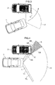
- FIG. 1 is a perspective view of an example of the vehicle vicinity monitoring system pertaining to the present invention when mounted onto a vehicle.
- FIG. 2 is a block diagram depicting an overview of the vehicle vicinity monitoring system pertaining to the present invention.
- a vehicle 1 as depicted in FIG. 1 is a mobile object on which is mounted the vehicle vicinity monitoring system pertaining to the present invention.
- a camera 3 is provided to the vehicle 1 as an image-capturing device so as to capture images of a rear view of the vehicle 1.
- the image-capturing device may be provided to the front side of the vehicle 1, and may be provided to both the front side and the rear side. In the present embodiment, an example of a rear installation is used for descriptive purposes.
- the vehicle 1 is also provided with an additional lighting device 4, which differs from illumination devices such as front positioned lights. This lighting device 4 is described below.
- Images taken by the camera 3 are input to a vicinity monitor ECU (Electronic Control Unit) 5, where image processing is performed by an image processing unit to perform border extraction and edge enhancement. Passengers(occupants) are notified of the results of the image processing via the notification device 6, which comprises a monitor 6a and a speaker 6b.
- the vicinity monitor ECU 5 also comprises a control unit and a display control unit.
- the control unit performs various decisions based on the results of image processing.
- a display control unit is used to control what the monitor 6a is to display.
- the display control unit is used to display the image obtained by the camera 3, and to superimpose the results of image processing or the results of control unit decisions, or to superimpose resulting images as a guideline.
- the results of the control unit decisions are also supplied to other ECUs in the vehicle 1. For example, if information that an obstacle is being approached too closely is transmitted to a motion control ECU 8, the motion control ECU 8 will apply a brake device, halting the vehicle 1.
- a steering wheel angle sensor 7a for detecting the operation of a steering wheel 9a, a wheel speed sensor 7b, and a shift lever switch 7c for detecting the shift position of a shift lever 9c correspond to the movement state detection means.
- the vicinity monitor ECU 5 calculates the direction of movement, the speed of movement, and the predicted path of travel of the vehicle 1.
- FIG. 3 is a descriptive diagram indicating an initial movement where the vehicle 1 is parallel parking behind a parked vehicle 2, which is used as the obstacle. The vehicle 1 moves towards the rear of the parked vehicle 2, following a path indicated by the arrow in FIG. 3. At this time, the camera 3 on the vehicle 1 captures the scene in an imaging field V.
- FIG. 4 is a descriptive diagram that shows an example where a shadow S of the parked vehicle 2 is created in the imaging field V of the camera 3.
- FIG. 4 shows the vehicle 1 and the parked vehicle 2 in a substantially parallel alignment for simplifying the description.
- the imaging field V formed by the right side limit of visibility VR and the left side limit of visibility VL indicates the angle of vision of the camera 3 mounted on the vehicle 1.
- the area between the solid line LR and the solid line LL indicates the area where illuminating light reaches when the illumination device (for example, at least a tail lamp, or a brake lamp) provided to the vehicle 1 is illuminated.
- the illumination device for example, at least a tail lamp, or a brake lamp
- the boundary line of the illuminating light is the line connecting the corner C, which is the outermost edge of the parked car 2, and the illuminated illumination device.
- the illuminating light from the illumination device is cut off at the portion located away from the vehicle 1 in the vehicle width direction relative to the boundary line of the illuminating light LS, resulting in a shadow S.
- the angle of vision VS obtained when viewing the corner C of the parked vehicle 2 from the camera 3 (indicated by a solid arrow line) is oriented in a direction away from the vehicle 1 relative to the boundary line of the illuminating light LS.
- the angle of vision VS will capture the shadow S of the parked vehicle 2 created by the illumination device, which provides illumination beyond the corner C of the parked vehicle 2.
- the shadow S of the parked vehicle 2 will appear in the captured image as a background area, which normally comprises road and wall surfaces. If the color of the parked vehicle 2 is a dark color such as black or dark blue, the contrast between the parked vehicle 2 and the shadow S will decrease. As a result, distinguishing the boundary area of the parked vehicle 2 will be complicated when image processing is performed by the vicinity monitor ECU 5. In other words, it becomes difficult to perform precise detection of the corner C, which is the most closely approached corner when the vehicle 1 is moving in a manner as shown in FIG. 3.
- the vehicle vicinity monitoring system pertaining to the present invention prevents the dark shadow S from being included in the captured image to an extent that contrast with the parked vehicle 2 is lowered. It is not necessary to completely eliminate the shadow S. It is sufficient to lighten the shadow S to provide a level of contrast allowing the vicinity monitor ECU 5 to sufficiently distinguish between the parked vehicle 2 and the background.
- the vehicle vicinity monitoring system pertaining to the present invention includes a lighting device 4 (the primary lighting device) as supplemental illumination means, separate from the illumination device which generated shadows from obstacles, for the purposes of lightening the shadow S.
- the lighting device 4 directs light outward from the vehicle 1 relative to the angle of vision VS. It is preferable that light from this lighting device 4 be directed while the illumination device is in an illuminated state. This is because when the illumination device is in an extinguished state, it will often be the case that the vicinity will be bright if it is daytime, or the vehicle 1 is not moving.
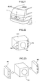
- FIG. 6 is a descriptive diagram that shows an example of the positioning of the lighting device 4 used as supplemental illumination means, and the camera 3 used as the image-capturing device.
- FIG. 6(a) is a sample setup with the illumination device 4 installed a prescribed distance from the camera 3 in the vehicle width direction, directing light to the opposite left/right direction in the width direction of vehicle 1, across from the camera 3. A more detailed description shall be provided hereunder, but this configuration allows for light to be directed away(outward) from the vehicle 1 relative to the angle of vision VS from the camera 3 to the parked vehicle 2, and therefore enables the shadow S to be satisfactorily lightened.
- FIG. 6 is a descriptive diagram that shows an example of the positioning of the lighting device 4 used as supplemental illumination means, and the camera 3 used as the image-capturing device.
- FIG. 6(a) is a sample setup with the illumination device 4 installed a prescribed distance from the camera 3 in the vehicle width direction, directing light to the opposite left/right direction in the width direction of vehicle 1, across from the camera 3.
- 6(b) is a sample setup with the illumination device 4 provided to substantially the same position as the camera 3 in the width direction of the vehicle, and light being directed in the same direction as the angle of vision VS of the camera 3.
- the shadow S can be satisfactorily lightened if light is directed away from the vehicle 1 relative to that direction.
- the lighting device 4 is equipped with a projector 4a and a lens 4b, allowing for illumination by spot lighting in an area that includes a field of illumination P.
- This spot lighting P can be a simple spot lighting P as shown in FIG. 7(a), or it can be a plurality of spot lighting P as shown in FIG. 7(b).
- FIG. 8 is a descriptive diagram that shows an example where the effects of the shadow S are decreased by the use of a setup as shown in FIG. 6(a).
- the angle of vision VS of the camera 3 is oriented in a direction away(outward) from the vehicle, beyond the boundary line of illumination LS, which connects the illuminating illumination device and the corner C (the outermost edge of the parked vehicle 2).
- a beam of light PS created by the spotlight P from the lighting device 4 provided to the edge on the side opposite the parked vehicle 2
- the shadow S will be illuminated by the lighting device 4 and become lighter.
- the angle of vision VS will extend beyond the corner C, allowing road surfaces, wall surfaces, and other aspects of the scenery to be seen, and making it possible to lessen the effects of the shadow S.
- FIG. 9 is a descriptive diagram that shows an example where the effect of the shadow S is reduced by using the setup as shown in FIG. 6(b).
- the beam of light PS created by a spotlight P from the lighting device 4 installed at the same position as camera 3 in the width direction of the vehicle is approximately the same as the angle of vision PS.
- the shadow S is illuminated by the lighting device 4 closer to the vehicle 1 relative to the beam of light PS, and the shadow S is thereby lightened. Areas where the shadow S appears darker are on the side away from the vehicle 1 in the width direction, using the angle of vision VS as a reference. As a result, the angle of vision VS will extend beyond the corner C, allowing road surfaces, wall surfaces, and other aspects of the scenery to be seen, and making it possible to lessen the effects of the shadow S.
- FIG. 10 shows an example of a captured image taken in FIG. 8 and FIG. 9. In this manner, it is possible to obtain a captured image in which the contrast between the parked vehicle 2 and the background is strong.
- the vehicle vicinity monitoring system pertaining to the present invention includes a lighting device 4 (the secondary lighting device) as supplemental illumination means, separate from the illumination device which generated shadows from obstacles.
- the lighting device 4 projects light with a prescribed pattern onto the parked vehicle 2 and the background, including at least the angle of vision VS.
- the projection from the lighting device 4 is performed while the illumination device is in an illuminated state. This is because when the illumination device is in an extinguished state, it will often be the case that the vicinity will be bright if it is daytime, or the vehicle 1 is not moving.
- FIG. 6 is a descriptive diagram depicting an example of the positioning of the lighting device 4 and the camera 3.
- the positioning of each is as described above, and a description of such will accordingly be omitted here.
- the lighting device 4 projects away from the vehicle 1 relative to the angle of vision VS from the camera 3 to the parked vehicle 2.
- the illuminating light from the lighting device 4 that is reflected by the parked vehicle 2 and captured by the camera 3 to approximate mirror-reflected light.
- the amount of light reflected is maximized when the reflection is directly opposite, and this will allow for optimal specified pattern reconstruction by the camera 3.
- the lighting device 4 is able to project illuminating light having the prescribed pattern on both the parked vehicle 4 and the background. Illuminating light from the lighting device 4 is of a prescribed width. Therefore, projecting illuminating light with the prescribed pattern in the direction of the angle of vision VS from the position of the camera 3 makes it possible to project the illuminating light with the specified pattern onto the boundary between the parked vehicle 2 and the background. As a result, it is possible for the camera 3 to clearly capture the boundary of the vehicle.
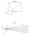
- the lighting device 4 is provided with a projector 4c and a lens 4d, and illuminating light having a prescribed pattern is projected therefrom, as shown in FIGS. 11 and 12.
- FIG. 12 shows an example where light with a straight line slit pattern is projected.
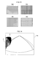
- FIG. 13 shows an example of a variety of prescribed patterns, including light with a straight line slit.
- FIG. 13(a) shows a horizontal straight line pattern. Using a pattern like this one allows for the boundaries to be satisfactorily located according to whether the continuity in a horizontal direction is disrupted.
- FIG. 13(b) shows a vertical straight line pattern. Using a pattern like this one allows for the boundaries to be satisfactorily located according to whether the continuity in a vertical direction is disrupted.
- FIG. 13(a) shows a horizontal straight line pattern. Using a pattern like this one allows for the boundaries to be satisfactorily located according to whether the continuity in a vertical direction is disrupted.
- FIG. 13(a) shows a horizontal straight
- FIG. 13(c) shows a lattice pattern. Using a pattern like this one allows for the boundaries to be satisfactorily located according to according to whether the continuity in the vertical and horizontal directions are disrupted. Alternatively, the boundary can be found according to the shape of the surface of the obstacle by the presence or absence of replication of the square pattern in the lattice.
- FIG. 13(d) is a dotted pattern. In this case, too, the boundary can be found according to the shape of the surface by the presence or absence of replication of the dotted pattern.
- FIG. 14 shows an example of a captured image taken with the prescribed pattern of FIG. 13(a) being projected by the lighting device 4.
- the straight line pattern will only be replicated in locations where the parked vehicle 2 exists. In this manner, it is possible to use discontinuities in the straight line pattern to determine the boundary between the parked vehicle 2 and the background from the captured image, even when the contrast between the parked vehicle 2 and the background is low.
- light projected by the lighting device 4 includes, in whole or in part, near-infrared light.
- the camera 3 is assumed to be sensitive to near-infrared light.
- Near-infrared light is not visible light, and so it is possible to optimally find these boundaries not only in cases where the effects of the shadows need to be controlled, but also when boundaries between the obstacle and the background are indistinct due to a lack of brightness in the environs. Additionally, because visible light is not projected onto the parked vehicle 2, vicinity monitoring can be performed without causing discomfort to third-party viewers.
- FIGS. 1, 2, and 6, Two lighting devices 4 are provided in FIGS. 1, 2, and 6, which are all referenced in Embodiments 1 and 2.
- the two lighting devices 4 do not necessarily have to be provided when the present invention is used.
- multiple lighting devices 4 are installed, as in the embodiments above, it is possible to create an optimal vicinity monitoring system without being constrained by the ease of visibility from the driver's seat.
- the direction of illumination (projection) of lighting device 4 is taken as being variable, and a configuration can be adopted wherein one lighting device 4 directs (projects) light in a plurality of directions.
- An alternative configuration may be adopted wherein only one of two lighting devices 4 is used to direct (project) light.
- the movement state detection means 7 comprises a steering wheel angle sensor 7a, a wheel speed sensor 7b, and a shift lever switch 7c. It is possible to determine that the direction of movement will be, e.g., to the rear by detecting that the shift lever switch 7c is in the reverse gear. It is also possible to learn whether the vehicle will be moving in a right or left direction using the steering wheel angle sensor 7a to detect the angle at which the steering wheel 9a is being operated. It is also possible to learn whether the vehicle will be moving in a right or left direction using the wheel speed sensor 7b to detect the difference in speed of the left and right wheels of the vehicle. Furthermore, it is possible to learn the speed in which the vehicle is moving at that time.
- the following illustrates a variety of examples of a lighting device installation embodiment.
- the description will be provided using a station wagon-type vehicle as the vehicle 1.
- the following installation examples apply to both embodiments of the lighting device 4 (the primary lighting device and the secondary lighting device).
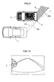
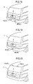
- FIG. 15 is a perspective view depicting a first installation example of the lighting device 4.
- FIG. 15 shows an example in which the lighting device 4 is installed a prescribed distance from the camera 3 in the width direction of the vehicle 1. As shown in the diagram, the camera 3 is installed as the image-capturing device in the center area in the width direction of the vehicle 1.
- the lighting devices 4 (4L and 4R) are provided to a rear combination lamp unit (illumination device), along with brake lamps, tail lamps, reverse lamps, and the like (illumination devices).
- FIG. 16 is a perspective view depicting a second installation example of the lighting device 4.
- FIG. 16 shows an example in which the lighting device 4 is installed a prescribed distance from the camera 3 in the width direction of the vehicle 1. As shown in the diagram, the camera 3 is installed as the image-capturing device in the center area in the width direction of the vehicle 1.
- the lighting devices 4 (4L and 4R) are provided to a rear combination lamp unit (illumination device), along with vehicle side lamps, turn signals, and the like (illumination devices).
- FIG. 17 is a perspective view depicting a third installation example of the lighting device 4.
- FIG. 17 shows an example in which the lighting device 4 is provided to the same location as the camera 3 in the width direction of the vehicle 1.
- the lighting device 4 can be a single device that directs light in multiple directions, or may be multiple devices provided to a single location.
- the lighting device 4 is provided along with the camera 3 onto a garnish, which is an external part of the vehicle 1.
- a license plate lamp which is an illumination device provided to the license plate.
- FIG. 22 it is possible to form a single unit by providing the camera unit 3a (the camera 3) to the center, and providing lighting units 4a (lighting devices 4) on the left and right sides of the camera in slanted directions relative to the optical axis thereof. Also, as shown in FIG. 23, it is possible to position lighting members 4A (lighting devices 4) overlaying both sides of a camera member 3A (camera 3), or to have the camera member 3A and lighting materials 4A joined together.
- FIG. 18 is a perspective view depicting a fourth installation example of the lighting device 4.
- FIG. 18 shows an example in which the lighting device 4 is installed a prescribed distance from the camera 3 in the width direction of the vehicle 1.
- the camera 3 is installed as the image-capturing device in the center area along the width direction of the vehicle 1, and the lighting devices 4 (4L and 4R) are provided to a bumper, which is an external part.
- FIG. 19 is a perspective view depicting a fifth installation example of the lighting device 4.
- FIG. 19 shows an example in which the lighting device 4 is provided to the same location as the camera 3 in the width direction of the vehicle 1.
- the lighting device 4 can be a single device that directs light in multiple directions, or may be multiple devices provided to a single location.
- the lighting device 4 is installed separately from the camera 3 onto a bumper, which is an external part of the vehicle 1.
- FIG. 20 is a perspective view depicting a sixth installation example of the lighting device 4.
- FIG. 20 shows an example in which the lighting device 4 is installed a prescribed distance from the camera 3 in the width direction of the vehicle 1.
- the camera 3 is installed as the image-capturing device in the center area in the width direction of the vehicle 1, and the lighting devices 4 (4L and 4R) are provided to a spoiler, which is an external part. If an illumination device such as a brake light is provided to the spoiler, then the lighting device 4 can be installed along with that illumination device.
- FIG. 21 is a perspective view depicting a seventh installation example of the lighting device 4.
- FIG. 21 shows an example in which the lighting device 4 is provided to the same location as the camera 3 in the width direction of the vehicle 1.
- the lighting device 4 can be a single device that directs light in multiple directions, or may be multiple devices provided to a single location.
- the lighting device 4 is installed separately from the camera 3 onto a spoiler, which is an external part of the vehicle 1.
- an illumination device such as a brake light
- the lighting device 4 can be installed along with that illumination device.
- the present invention can be applied to a vehicle vicinity monitoring system, a driving support system, or other system for detecting obstacles existing in the vicinity of a vehicle and providing vehicle occupants with information related to those obstacles.
Applications Claiming Priority (4)
| Application Number | Priority Date | Filing Date | Title |
|---|---|---|---|
| JP2005131421A JP4730589B2 (ja) | 2005-04-28 | 2005-04-28 | 車両周辺監視システム |
| JP2005131420A JP4730588B2 (ja) | 2005-04-28 | 2005-04-28 | 車両周辺監視システム |
| JP2005131419A JP4849298B2 (ja) | 2005-04-28 | 2005-04-28 | 車両周辺監視システム |
| PCT/JP2006/308553 WO2006118076A1 (fr) | 2005-04-28 | 2006-04-24 | Systeme de surveillance peripherique d’un vehicule |
Publications (2)
| Publication Number | Publication Date |
|---|---|
| EP1876829A1 true EP1876829A1 (fr) | 2008-01-09 |
| EP1876829A4 EP1876829A4 (fr) | 2010-06-09 |
Family
ID=37307876
Family Applications (1)
| Application Number | Title | Priority Date | Filing Date |
|---|---|---|---|
| EP06732264A Withdrawn EP1876829A4 (fr) | 2005-04-28 | 2006-04-24 | Systeme de surveillance de la peripherie d'un vehicule |
Country Status (3)
| Country | Link |
|---|---|
| US (1) | US20090309710A1 (fr) |
| EP (1) | EP1876829A4 (fr) |
| WO (1) | WO2006118076A1 (fr) |
Cited By (8)
| Publication number | Priority date | Publication date | Assignee | Title |
|---|---|---|---|---|
| WO2008134715A1 (fr) | 2007-04-30 | 2008-11-06 | Mobileye Technologies Ltd. | Détection d'obstruction arrière |
| GB2473338A (en) * | 2010-09-02 | 2011-03-09 | Julian Stevens | Terrain visualization device with light emitter projecting contrast pattern |
| WO2014108560A1 (fr) * | 2013-01-14 | 2014-07-17 | Robert Bosch Gmbh | Procédé et dispositif pour la production d'une image panoramique d'un environnement de véhicule d'un véhicule, procédé de production d'au moins une fonction d'aide à la conduite pour un véhicule, système à vue panoramique pour un véhicule |
| WO2018036646A1 (fr) * | 2016-08-26 | 2018-03-01 | Daimler Ag | Procédé et dispositif de détection de l'état d'ouverture d'une porte de garage |
| US10341442B2 (en) | 2015-01-12 | 2019-07-02 | Samsung Electronics Co., Ltd. | Device and method of controlling the device |
| WO2020109237A1 (fr) * | 2018-11-26 | 2020-06-04 | Zkw Group Gmbh | Système de vision de véhicule avec feux de recul adaptative |
| DE102010039092B4 (de) * | 2009-09-02 | 2020-10-22 | Robert Bosch Gmbh | Verfahren und Steuergerät zum Ermitteln eines Abstandes eines Objektes von einem Fahrzeug |
| US11667231B2 (en) | 2018-11-26 | 2023-06-06 | Magna Electronics Solutions Gmbh | Vehicle vision system with self-calibrating imager |
Families Citing this family (45)
| Publication number | Priority date | Publication date | Assignee | Title |
|---|---|---|---|---|
| US20080316312A1 (en) * | 2007-06-21 | 2008-12-25 | Francisco Castillo | System for capturing video of an accident upon detecting a potential impact event |
| US20100231715A1 (en) * | 2009-03-11 | 2010-09-16 | Delphi Technologies, Inc. | Sideview Vision System Displaying A View Dependent Upon Transmission Selector |
| JP5324310B2 (ja) * | 2009-05-14 | 2013-10-23 | 富士通テン株式会社 | 車載照明装置、画像処理装置及び画像表示システム |
| JP5503259B2 (ja) * | 2009-11-16 | 2014-05-28 | 富士通テン株式会社 | 車載照明装置、画像処理装置及び画像表示システム |
| US20110133914A1 (en) * | 2009-12-04 | 2011-06-09 | Delphi Technologies, Inc. | Image based vehicle object detection sensor with range finder |
| JP5629521B2 (ja) * | 2010-07-29 | 2014-11-19 | パナソニック株式会社 | 障害物検知システム及び方法、障害物検知装置 |
| US10691219B2 (en) | 2012-01-17 | 2020-06-23 | Ultrahaptics IP Two Limited | Systems and methods for machine control |
| US9679215B2 (en) | 2012-01-17 | 2017-06-13 | Leap Motion, Inc. | Systems and methods for machine control |
| US9070019B2 (en) | 2012-01-17 | 2015-06-30 | Leap Motion, Inc. | Systems and methods for capturing motion in three-dimensional space |
| US8638989B2 (en) | 2012-01-17 | 2014-01-28 | Leap Motion, Inc. | Systems and methods for capturing motion in three-dimensional space |
| US9501152B2 (en) | 2013-01-15 | 2016-11-22 | Leap Motion, Inc. | Free-space user interface and control using virtual constructs |
| US11493998B2 (en) | 2012-01-17 | 2022-11-08 | Ultrahaptics IP Two Limited | Systems and methods for machine control |
| US8693731B2 (en) | 2012-01-17 | 2014-04-08 | Leap Motion, Inc. | Enhanced contrast for object detection and characterization by optical imaging |
| US9285893B2 (en) | 2012-11-08 | 2016-03-15 | Leap Motion, Inc. | Object detection and tracking with variable-field illumination devices |
| US10609285B2 (en) | 2013-01-07 | 2020-03-31 | Ultrahaptics IP Two Limited | Power consumption in motion-capture systems |
| US9465461B2 (en) | 2013-01-08 | 2016-10-11 | Leap Motion, Inc. | Object detection and tracking with audio and optical signals |
| US9459697B2 (en) | 2013-01-15 | 2016-10-04 | Leap Motion, Inc. | Dynamic, free-space user interactions for machine control |
| US10042510B2 (en) | 2013-01-15 | 2018-08-07 | Leap Motion, Inc. | Dynamic user interactions for display control and measuring degree of completeness of user gestures |
| US9702977B2 (en) | 2013-03-15 | 2017-07-11 | Leap Motion, Inc. | Determining positional information of an object in space |
| US10620709B2 (en) | 2013-04-05 | 2020-04-14 | Ultrahaptics IP Two Limited | Customized gesture interpretation |
| US9916009B2 (en) | 2013-04-26 | 2018-03-13 | Leap Motion, Inc. | Non-tactile interface systems and methods |
| US9747696B2 (en) | 2013-05-17 | 2017-08-29 | Leap Motion, Inc. | Systems and methods for providing normalized parameters of motions of objects in three-dimensional space |
| US10281987B1 (en) | 2013-08-09 | 2019-05-07 | Leap Motion, Inc. | Systems and methods of free-space gestural interaction |
| US9721383B1 (en) | 2013-08-29 | 2017-08-01 | Leap Motion, Inc. | Predictive information for free space gesture control and communication |
| US9632572B2 (en) | 2013-10-03 | 2017-04-25 | Leap Motion, Inc. | Enhanced field of view to augment three-dimensional (3D) sensory space for free-space gesture interpretation |
| US9996638B1 (en) | 2013-10-31 | 2018-06-12 | Leap Motion, Inc. | Predictive information for free space gesture control and communication |
| US9613262B2 (en) | 2014-01-15 | 2017-04-04 | Leap Motion, Inc. | Object detection and tracking for providing a virtual device experience |
| US9342747B2 (en) | 2014-04-14 | 2016-05-17 | Bendix Commercial Vehicle Systems Llc | Vehicle driver assistance apparatus for assisting a vehicle driver in maneuvering the vehicle relative to an object |
| JP6178280B2 (ja) * | 2014-04-24 | 2017-08-09 | 日立建機株式会社 | 作業機械の周囲監視装置 |
| BR112017002129B1 (pt) * | 2014-08-04 | 2022-01-04 | Nissan Motor Co., Ltd | Aparelho de cálculo de autoposição e método de cálculo de autoposição |
| CN204480228U (zh) | 2014-08-08 | 2015-07-15 | 厉动公司 | 运动感测和成像设备 |
| DE112015005020T5 (de) | 2014-11-05 | 2017-07-27 | Trw Automotive U.S. Llc | Verbesserte objektdetektion unter verwendung von strukturiertem licht |
| KR101724921B1 (ko) * | 2015-10-08 | 2017-04-07 | 현대자동차주식회사 | 파워 테일 게이트 제어 장치 및 그 방법 |
| TWI596361B (zh) * | 2015-12-07 | 2017-08-21 | Metal Ind Res And Dev Centre | Using structured light sensing barrier reversing warning method |
| KR101759138B1 (ko) * | 2015-12-10 | 2017-07-18 | 현대자동차주식회사 | 차량의 후방 카메라를 이용한 테일 게이트 제어 장치 및 방법 |
| US10789850B2 (en) * | 2016-05-10 | 2020-09-29 | Mitsubishi Electric Corporation | Obstacle detection device, driving assistance system, and obstacle detection method |
| US10569613B2 (en) * | 2016-10-03 | 2020-02-25 | Tenneco Automotive Operating Company Inc. | Method of alerting driver to condition of suspension system |
| WO2019026204A1 (fr) * | 2017-08-02 | 2019-02-07 | 三菱電機株式会社 | Structure de montage de feu de revêtement routier |
| WO2019139959A1 (fr) | 2018-01-12 | 2019-07-18 | Intelligent Security Systems Corporation | Systèmes et procédés de sortie de lumière à partir d'une image |
| US11875012B2 (en) | 2018-05-25 | 2024-01-16 | Ultrahaptics IP Two Limited | Throwable interface for augmented reality and virtual reality environments |
| CN113170057B (zh) * | 2018-12-12 | 2023-06-13 | 日立安斯泰莫株式会社 | 摄像部控制装置 |
| JP7252755B2 (ja) * | 2018-12-27 | 2023-04-05 | 株式会社小糸製作所 | アクティブセンサ、物体識別システム、車両、車両用灯具 |
| KR20220155848A (ko) * | 2021-05-17 | 2022-11-24 | 현대자동차주식회사 | 주차 안내 시스템 및 방법 |
| FR3124252B1 (fr) * | 2021-06-18 | 2023-10-27 | Valeo Vision | Procédé de détection d'un objet sur une surface de route, procédé de conduite autonome et dispositif d'éclairage automobile |
| FR3124254B1 (fr) * | 2021-06-18 | 2024-02-16 | Valeo Vision | Procédé de détection d'un objet sur une surface de route, procédé de conduite autonome et dispositif d'éclairage automobile |
Citations (7)
| Publication number | Priority date | Publication date | Assignee | Title |
|---|---|---|---|---|
| JPH01240811A (ja) * | 1988-03-23 | 1989-09-26 | Alpine Electron Inc | 車両用の距離判別装置 |
| JPH09150670A (ja) * | 1995-11-28 | 1997-06-10 | Sony Corp | 車後方確認システム |
| US6285778B1 (en) * | 1991-09-19 | 2001-09-04 | Yazaki Corporation | Vehicle surroundings monitor with obstacle avoidance lighting |
| US6550949B1 (en) * | 1996-06-13 | 2003-04-22 | Gentex Corporation | Systems and components for enhancing rear vision from a vehicle |
| DE10226278A1 (de) * | 2002-06-13 | 2003-12-24 | Peter Lux | Rückfahrhilfe für Fahrzeuge |
| EP1400410A2 (fr) * | 1999-06-25 | 2004-03-24 | Fujitsu Ten Limited | Système d'assistance de conduir pour véhicules |
| US6717610B1 (en) * | 1998-11-25 | 2004-04-06 | Donnelly Corporation | Wide angle image capture system for vehicle |
Family Cites Families (9)
| Publication number | Priority date | Publication date | Assignee | Title |
|---|---|---|---|---|
| US7663502B2 (en) * | 1992-05-05 | 2010-02-16 | Intelligent Technologies International, Inc. | Asset system control arrangement and method |
| JP3570635B2 (ja) * | 1994-03-23 | 2004-09-29 | 矢崎総業株式会社 | 車両周辺監視装置 |
| JPH0818949A (ja) * | 1994-06-27 | 1996-01-19 | Olympus Optical Co Ltd | 車載用画像処理装置 |
| US5803579A (en) * | 1996-06-13 | 1998-09-08 | Gentex Corporation | Illuminator assembly incorporating light emitting diodes |
| JP4723703B2 (ja) * | 1999-06-25 | 2011-07-13 | 富士通テン株式会社 | 車両の運転支援装置 |
| ATE333192T1 (de) * | 1999-10-12 | 2006-08-15 | Matsushita Electric Ind Co Ltd | Überwachungskamera, verfahren zum anpassen einer kamera und fahrzeugüberwachungssystem |
| JP2002114097A (ja) * | 2000-10-10 | 2002-04-16 | Showa Electric Wire & Cable Co Ltd | 車載用赤外線撮像装置 |
| JP2004274154A (ja) * | 2003-03-05 | 2004-09-30 | Denso Corp | 車両用乗員保護装置 |
| US7218792B2 (en) * | 2003-03-19 | 2007-05-15 | Mitsubishi Electric Research Laboratories, Inc. | Stylized imaging using variable controlled illumination |
-
2006
- 2006-04-24 WO PCT/JP2006/308553 patent/WO2006118076A1/fr active Application Filing
- 2006-04-24 US US11/919,434 patent/US20090309710A1/en not_active Abandoned
- 2006-04-24 EP EP06732264A patent/EP1876829A4/fr not_active Withdrawn
Patent Citations (7)
| Publication number | Priority date | Publication date | Assignee | Title |
|---|---|---|---|---|
| JPH01240811A (ja) * | 1988-03-23 | 1989-09-26 | Alpine Electron Inc | 車両用の距離判別装置 |
| US6285778B1 (en) * | 1991-09-19 | 2001-09-04 | Yazaki Corporation | Vehicle surroundings monitor with obstacle avoidance lighting |
| JPH09150670A (ja) * | 1995-11-28 | 1997-06-10 | Sony Corp | 車後方確認システム |
| US6550949B1 (en) * | 1996-06-13 | 2003-04-22 | Gentex Corporation | Systems and components for enhancing rear vision from a vehicle |
| US6717610B1 (en) * | 1998-11-25 | 2004-04-06 | Donnelly Corporation | Wide angle image capture system for vehicle |
| EP1400410A2 (fr) * | 1999-06-25 | 2004-03-24 | Fujitsu Ten Limited | Système d'assistance de conduir pour véhicules |
| DE10226278A1 (de) * | 2002-06-13 | 2003-12-24 | Peter Lux | Rückfahrhilfe für Fahrzeuge |
Non-Patent Citations (1)
| Title |
|---|
| See also references of WO2006118076A1 * |
Cited By (23)
| Publication number | Priority date | Publication date | Assignee | Title |
|---|---|---|---|---|
| US9826200B2 (en) | 2007-04-30 | 2017-11-21 | Mobileye Vision Technologies Ltd. | Rear obstruction detection |
| EP2674323A1 (fr) | 2007-04-30 | 2013-12-18 | Mobileye Technologies Limited | Détection d'obstruction arrière |
| US10827151B2 (en) | 2007-04-30 | 2020-11-03 | Mobileye Vision Technologies Ltd. | Rear obstruction detection |
| US10389985B2 (en) | 2007-04-30 | 2019-08-20 | Mobileye Vision Tehcnologies Ltd. | Obstruction detection |
| EP3480057A1 (fr) | 2007-04-30 | 2019-05-08 | Mobileye Vision Technologies Ltd. | Détection d'obstruction arrière |
| EP2674324A1 (fr) | 2007-04-30 | 2013-12-18 | Mobileye Technologies Limited | Détection d'obstruction arrière |
| WO2008134715A1 (fr) | 2007-04-30 | 2008-11-06 | Mobileye Technologies Ltd. | Détection d'obstruction arrière |
| DE102010039092B4 (de) * | 2009-09-02 | 2020-10-22 | Robert Bosch Gmbh | Verfahren und Steuergerät zum Ermitteln eines Abstandes eines Objektes von einem Fahrzeug |
| CN103221775A (zh) * | 2010-09-02 | 2013-07-24 | 朱利安·史蒂文斯 | 地形可视化装置 |
| GB2473338A (en) * | 2010-09-02 | 2011-03-09 | Julian Stevens | Terrain visualization device with light emitter projecting contrast pattern |
| WO2012028855A1 (fr) * | 2010-09-02 | 2012-03-08 | Julian Stevens | Dispositif de visualisation de terrain |
| WO2012028837A1 (fr) * | 2010-09-02 | 2012-03-08 | Julian Stevens | Dispositif de visualisation de terrain |
| CN105073496A (zh) * | 2013-01-14 | 2015-11-18 | 罗伯特·博世有限公司 | 用于产生车辆的车辆周围环境的全方位视野图像的方法和设备、用于提供至少一个用于车辆的驾驶员辅助功能的方法、用于车辆的全方位视野系统 |
| WO2014108560A1 (fr) * | 2013-01-14 | 2014-07-17 | Robert Bosch Gmbh | Procédé et dispositif pour la production d'une image panoramique d'un environnement de véhicule d'un véhicule, procédé de production d'au moins une fonction d'aide à la conduite pour un véhicule, système à vue panoramique pour un véhicule |
| US10341442B2 (en) | 2015-01-12 | 2019-07-02 | Samsung Electronics Co., Ltd. | Device and method of controlling the device |
| WO2018036646A1 (fr) * | 2016-08-26 | 2018-03-01 | Daimler Ag | Procédé et dispositif de détection de l'état d'ouverture d'une porte de garage |
| US10586120B2 (en) | 2016-08-26 | 2020-03-10 | Daimler Ag | Method and apparatus for identifying the opening state of a garage door |
| WO2020109237A1 (fr) * | 2018-11-26 | 2020-06-04 | Zkw Group Gmbh | Système de vision de véhicule avec feux de recul adaptative |
| KR20210077774A (ko) * | 2018-11-26 | 2021-06-25 | 제트카베 그룹 게엠베하 | 적응형 후진 라이트를 갖는 차량 비전 시스템 |
| CN113272814A (zh) * | 2018-11-26 | 2021-08-17 | Zkw集团有限责任公司 | 具有自适应倒车灯的车辆视觉系统 |
| US11104279B2 (en) | 2018-11-26 | 2021-08-31 | Magna Electronics Solutions Gmbh | Vehicle vision system with adaptive reversing light |
| US11667231B2 (en) | 2018-11-26 | 2023-06-06 | Magna Electronics Solutions Gmbh | Vehicle vision system with self-calibrating imager |
| KR102549130B1 (ko) | 2018-11-26 | 2023-07-03 | 제트카베 그룹 게엠베하 | 적응형 후진 라이트를 갖는 차량 비전 시스템 |
Also Published As
| Publication number | Publication date |
|---|---|
| EP1876829A4 (fr) | 2010-06-09 |
| US20090309710A1 (en) | 2009-12-17 |
| WO2006118076A1 (fr) | 2006-11-09 |
Similar Documents
| Publication | Publication Date | Title |
|---|---|---|
| EP1876829A1 (fr) | Systeme de surveillance de la peripherie d'un vehicule | |
| JP5604146B2 (ja) | 車載照明装置、画像処理装置、画像表示システム及び照明方法 | |
| US10431185B2 (en) | Display system replacing side mirror and method for controlling output brightness thereof | |
| JP6120859B2 (ja) | 自律的、乃至、部分自律的運転マヌーバを実施するための車載アシスタント・システム用の方法、並びに、装置 | |
| KR102129478B1 (ko) | 자동차의 운전자 시야 관점에서의 광 조건 개선 방법 | |
| JP5324310B2 (ja) | 車載照明装置、画像処理装置及び画像表示システム | |
| US20200062168A1 (en) | Vehicle headlight control device | |
| KR20150095580A (ko) | 차량의 운전 지원 장치 | |
| GB2482951A (en) | Vehicle with projector to display information about driving conditions | |
| JP5313638B2 (ja) | 車両用前照灯装置 | |
| US20100238292A1 (en) | Exterior mirror for vehicle | |
| CN110087946B (zh) | 车辆用照明系统和车辆 | |
| US8749632B2 (en) | Image generation apparatus | |
| CN110121444B (zh) | 照明装置 | |
| JP4534871B2 (ja) | 車両用照明装置 | |
| JP5361901B2 (ja) | 前照灯制御装置 | |
| JP2013097885A (ja) | ヘッドライト装置、及びヘッドライトシステム | |
| JP4730589B2 (ja) | 車両周辺監視システム | |
| JPH06255399A (ja) | 車両の表示装置 | |
| JP2007145048A (ja) | 車両用照明装置 | |
| JP4735090B2 (ja) | 赤外画像撮像装置 | |
| JP5045974B2 (ja) | 車両運転支援装置 | |
| JP2020516528A (ja) | 車両用投光装置及び駐車プロセスの支援方法 | |
| US11794636B2 (en) | Headlamp and headlamp control system | |
| JP4849298B2 (ja) | 車両周辺監視システム |
Legal Events
| Date | Code | Title | Description |
|---|---|---|---|
| PUAI | Public reference made under article 153(3) epc to a published international application that has entered the european phase |
Free format text: ORIGINAL CODE: 0009012 |
|
| 17P | Request for examination filed |
Effective date: 20071023 |
|
| AK | Designated contracting states |
Kind code of ref document: A1 Designated state(s): DE FR |
|
| RBV | Designated contracting states (corrected) |
Designated state(s): DE FR |
|
| DAX | Request for extension of the european patent (deleted) | ||
| A4 | Supplementary search report drawn up and despatched |
Effective date: 20100511 |
|
| 17Q | First examination report despatched |
Effective date: 20140207 |
|
| STAA | Information on the status of an ep patent application or granted ep patent |
Free format text: STATUS: THE APPLICATION IS DEEMED TO BE WITHDRAWN |
|
| 18D | Application deemed to be withdrawn |
Effective date: 20170503 |