EP1874514B1 - Device for production of moulded concrete blocks - Google Patents
Device for production of moulded concrete blocks Download PDFInfo
- Publication number
- EP1874514B1 EP1874514B1 EP06723846A EP06723846A EP1874514B1 EP 1874514 B1 EP1874514 B1 EP 1874514B1 EP 06723846 A EP06723846 A EP 06723846A EP 06723846 A EP06723846 A EP 06723846A EP 1874514 B1 EP1874514 B1 EP 1874514B1
- Authority
- EP
- European Patent Office
- Prior art keywords
- holding
- clamping
- mold insert
- mould insert
- counter
- Prior art date
- Legal status (The legal status is an assumption and is not a legal conclusion. Google has not performed a legal analysis and makes no representation as to the accuracy of the status listed.)
- Not-in-force
Links
- 238000004519 manufacturing process Methods 0.000 title claims description 10
- 238000000465 moulding Methods 0.000 claims description 34
- 238000006073 displacement reaction Methods 0.000 claims description 16
- 230000008878 coupling Effects 0.000 claims description 12
- 238000010168 coupling process Methods 0.000 claims description 12
- 238000005859 coupling reaction Methods 0.000 claims description 12
- 239000012530 fluid Substances 0.000 claims description 9
- 238000000034 method Methods 0.000 claims description 8
- 230000008569 process Effects 0.000 claims description 8
- 238000005056 compaction Methods 0.000 claims description 2
- 239000004575 stone Substances 0.000 description 30
- 230000013011 mating Effects 0.000 description 8
- 238000007639 printing Methods 0.000 description 6
- 238000013016 damping Methods 0.000 description 3
- 239000000463 material Substances 0.000 description 3
- 239000002245 particle Substances 0.000 description 3
- 230000001133 acceleration Effects 0.000 description 2
- 230000009471 action Effects 0.000 description 2
- 238000007654 immersion Methods 0.000 description 2
- 239000000203 mixture Substances 0.000 description 2
- 238000007789 sealing Methods 0.000 description 2
- 230000035939 shock Effects 0.000 description 2
- 238000003860 storage Methods 0.000 description 2
- 239000000758 substrate Substances 0.000 description 2
- 230000000712 assembly Effects 0.000 description 1
- 238000000429 assembly Methods 0.000 description 1
- 230000008901 benefit Effects 0.000 description 1
- 150000001875 compounds Chemical class 0.000 description 1
- 230000006835 compression Effects 0.000 description 1
- 238000007906 compression Methods 0.000 description 1
- 230000007547 defect Effects 0.000 description 1
- 230000001419 dependent effect Effects 0.000 description 1
- 238000011161 development Methods 0.000 description 1
- 230000018109 developmental process Effects 0.000 description 1
- 239000013013 elastic material Substances 0.000 description 1
- 230000008030 elimination Effects 0.000 description 1
- 238000003379 elimination reaction Methods 0.000 description 1
- 230000005284 excitation Effects 0.000 description 1
- 238000005429 filling process Methods 0.000 description 1
- 230000010355 oscillation Effects 0.000 description 1
- 238000003825 pressing Methods 0.000 description 1
- 238000000926 separation method Methods 0.000 description 1
- 238000007493 shaping process Methods 0.000 description 1
- 239000007787 solid Substances 0.000 description 1
- 230000006641 stabilisation Effects 0.000 description 1
- 238000011105 stabilization Methods 0.000 description 1
- 230000001502 supplementing effect Effects 0.000 description 1
- 239000002023 wood Substances 0.000 description 1
Images


Classifications
-
- B—PERFORMING OPERATIONS; TRANSPORTING
- B28—WORKING CEMENT, CLAY, OR STONE
- B28B—SHAPING CLAY OR OTHER CERAMIC COMPOSITIONS; SHAPING SLAG; SHAPING MIXTURES CONTAINING CEMENTITIOUS MATERIAL, e.g. PLASTER
- B28B7/00—Moulds; Cores; Mandrels
- B28B7/0002—Auxiliary parts or elements of the mould
- B28B7/0014—Fastening means for mould parts, e.g. for attaching mould walls on mould tables; Mould clamps
-
- B—PERFORMING OPERATIONS; TRANSPORTING
- B28—WORKING CEMENT, CLAY, OR STONE
- B28B—SHAPING CLAY OR OTHER CERAMIC COMPOSITIONS; SHAPING SLAG; SHAPING MIXTURES CONTAINING CEMENTITIOUS MATERIAL, e.g. PLASTER
- B28B1/00—Producing shaped prefabricated articles from the material
- B28B1/08—Producing shaped prefabricated articles from the material by vibrating or jolting
- B28B1/087—Producing shaped prefabricated articles from the material by vibrating or jolting by means acting on the mould ; Fixation thereof to the mould
-
- B—PERFORMING OPERATIONS; TRANSPORTING
- B28—WORKING CEMENT, CLAY, OR STONE
- B28B—SHAPING CLAY OR OTHER CERAMIC COMPOSITIONS; SHAPING SLAG; SHAPING MIXTURES CONTAINING CEMENTITIOUS MATERIAL, e.g. PLASTER
- B28B3/00—Producing shaped articles from the material by using presses; Presses specially adapted therefor
- B28B3/02—Producing shaped articles from the material by using presses; Presses specially adapted therefor wherein a ram exerts pressure on the material in a moulding space; Ram heads of special form
- B28B3/022—Producing shaped articles from the material by using presses; Presses specially adapted therefor wherein a ram exerts pressure on the material in a moulding space; Ram heads of special form combined with vibrating or jolting
Definitions
- the invention relates to an apparatus for the production of concrete blocks by compacting fresh concrete in a molding machine under the action of shaking forces.
- a mold insert is removably mounted in a holding frame, which is vertically movable along vertical guide columns of a molding machine.
- the mold insert can be placed on a pad located below the mold frame and pressed by the holding frame on the substrate and can be excited by means of a vibrator to vibrate.
- a ballast with stamp plates is lowered into the upper openings of the mold cavity and presses on the fresh concrete.
- the pad is z. B. excited by rotating unbalanced masses or blow bars to vibrations, which are also transmitted to the mold insert and the fresh concrete.
- the compacted molded bodies can be removed from the mold cavities, for which purpose the mold frame is moved upwards and the stamps of the ballast hold the moldings on the substrate.
- the mold insert which is bolted to the support frame, is forced over the support frame with high force on the support. Between the pressing force transmitting, vertically opposite surfaces of support frame and mold insert a layer of damping material is inserted.
- a device in which a mold consists of a mold frame and a mold insert which is held in the mold frame by interposition of elastically prestressed damping material exists, which are handled as a form together and are not separated by the user. About flange strips on the outside of the mold frame, the mold in clamping positions of the molding machine is firmly clamped.
- a device according to the WO 03/092973 The forces between the mold frame and mold insert during the Rüttelvorgangs by a thin elastic layer, with which a gap between the mold frame and mold insert is poured, collected.
- the DE 103 33 743 A1 describes a device for the production of concrete blocks according to the preamble of claim 1, which contains a mold frame and a mold insert held therein. Attached to the mold frame holding elements engage with interposition of fluid-filled damping elements in recesses of the mold insert. The holding elements can be arranged displaceably on the mold frame, whereby the insert can be removed from the mold frame. From the DE 951 797 C is a stone forming machine is known in which a molding box is placed on a task table and held on an engagement of guide rods and guide sleeves on the work table.
- At one of the DE 203 01 954 U1 known device for shaping mixtures is a mold insert via bracing elements with a vibrating table, to which a harmonic oscillation system is attached coupled. To replace the mold, the bracing elements are released.
- the invention has for its object to provide an advantageous device for the production of concrete blocks.
- a releasable clamping device between mold insert and vibratory pad on the one hand and a releasable holding device between a machine-side support frame and the mold insert on the other hand results in an advantageous functional separation of different compounds of the mold insert in different periods of successive manufacturing cycles.
- a releasable clamping device between mold insert and vibratory pad on the one hand and a releasable holding device between a machine-side support frame and the mold insert on the other hand results in an advantageous functional separation of different compounds of the mold insert in different periods of successive manufacturing cycles.
- Of particular advantage is the possibility of loose coupling or preferably complete decoupling of the mold insert from the holding frame in the vibrating phase. In particular, no vertical contact forces between holding frame and mold insert are transmitted.
- the mold insert between two shaking in the engaged position of the holding devices on this with the holding frame, in particular its vertical mobility relative to the vibratory pad so rigidly coupled that a precise immersion of a pressure plate Auflastvoriques in the at least one mold cavity and the precise vertical position are reliably ensured by printing plates and bottom edge of the mold cavity during demolding.
- the insert is thus manageable as a conventional mold insert during filling and demolding.
- the power coupling between the holding frame and mold insert on the holding device is preferably completely canceled or greatly reduced so that during the vibration process, the holding frame measurable acceleration maximum 20%, in particular maximum 10% of the acceleration on the holding means connected part of the mold insert.
- the holding devices and clamping devices are automatically, in particular via a pressurized fluid, preferably hydraulically actuated.
- a control device in coordination with other actuators of the molding machine controls the timely operation of the holding devices and clamping devices.
- shock vibration can be used with blow bars.
- a vibrating device with vibration exciters between the base and a counterweight advantageously has a counterweight to the mold insert on the opposite.
- the holding devices advantageously have movable, preferably automatic, sides of the holding frame connected to the forming machine operable holding elements and on the side of the mold insert only passive counter-elements for releasable engagement with the holding elements.
- the passive counter-elements may in particular be openings in the mold insert into which the holding elements can be inserted.
- the holding elements are designed in an advantageous embodiment at least at their end facing the mold insert bolt-shaped.
- the opening in the mold insert is advantageously expanded on the holding frame facing away from the end of a region for the engagement of the holding elements and open at the bottom.
- the holding devices between the release position and the engagement position are substantially immovable and contain holding elements whose power coupling between the holding frame and mold insert is variable.
- the holding elements contain fluid-filled hollow body whose force coupling is adjustable by changing the fluid pressure via leads to the hollow bodies.
- the holding elements may contain magnetic coils which generate magnetic fields for the engagement position, in particular repulsive magnetic fields, wherein preferably on the side of the mold insert permanent magnets are arranged.
- the extensive decoupling of the holding frame from the mold insert during the shaking process, in particular the elimination of the vertical contact forces between the holding frame and mold insert also significantly simplifies the attachment a vertically movable in the molding machine and fixed during the shaking holding frame.
- the holding frame is advantageously made of only two arranged on opposite sides of the mold insert and individually connected to the molding machine retaining flanges or retaining strips.
- the support frame but in other embodiments, the mold insert as a U-shape to three or closed on all four sides surrounded.
- the holding elements hold the mold insert in a horizontal plane advantageously in a defined position, so that no further centering for precise alignment of mold insert and printing plates of a Auflastvoriques are necessary.
- the holding elements support the mold insert in a position lifted from the vibrating support, in particular during the demolding of the compacted concrete moldings from the mold insert.
- Clamping elements of the clamping devices engage advantageously from below into the mold insert in counter-elements, in particular in downwardly open and preferably closed up against the incidence of fresh concrete openings in the bottom of the mold insert.
- Clamping elements and counter-clamping elements are advantageously designed to rotate relative to each other.
- Contact surfaces for clamping the clamping devices can then advantageously be formed at least approximately as helical sections about the axis of rotation of clamping element or counter-clamping element.
- the clamping elements and counter-clamping elements engage in one another via a thread.
- the clamping devices brace for the shaking the mold insert against the pad with a force which is typically sufficient to to reliably prevent a lateral displacement of the decoupled from the frame mold insert on the pad.
- centering elements can be provided between the vibrating pad and the mold insert, which engage positively with one another on the vibrating pad mold insert with structures and counter-structures and determine the position of the mold insert on the vibrating pad and secure against horizontal displacement of the mold insert relative to the pad.
- an intermediate layer usually in the form of a wooden board, which serves mainly for the one-layer production as a support for the removal and storage of the concrete moldings ,
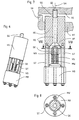
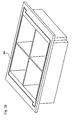
- Fig. 1 shows in an oblique view from above a vertically movable in a molding machine in the vertical z-direction holding frame in which vertically spaced from a Rüttelunterlage a mold insert is held.
- the support frame consists in the preferred example outlined of two arranged in the horizontal ⁇ -direction of the marked coordinate system on opposite sides of the mold insert FE retaining strips HLL, HLR.
- the retaining strips are permanently connected to the machine and provided for receiving various interchangeable mold inserts.
- the retaining strips are vertically movable in a conventional manner for holding frame by means of hydraulic cylinders and guided in vertical guides, which may also be formed by the hydraulic cylinder itself. For reasons of clarity, only the vertical guides are indicated by the molding machine.
- the mold insert has in a central region a stone field with a plurality of mold cavities FN, which form up and down open receptacles for fresh concrete or a similar mixture.
- the mold cavities essentially determine the shape of the concrete moldings produced on the mold insert.
- connection areas ABL and ABR which in sketched example zoom up to a narrow gap SP to the associated retaining strips.
- connection areas ABL and ABR counter holding elements are arranged to holding devices between retaining strips and mold insert and counter-clamping elements of clamping devices for vertical clamping of the mold insert against the Studttelunterlage, which hereinafter with reference to advantageous Embodiments are illustrated.
- the engaged holding means determine the horizontal position of the mold insert with respect to the retaining strips and couple the mold insert to the vertical displacement of the retaining strips along the vertical guides.
- the vibratory pad is shown in the example sketched as a rectangular vibrating table RT, which can be excited to vibrations only schematically indicated vibrators RE, the vibrations preferably have predominantly vertical components.
- vibrating devices which are known per se to the person skilled in the art, in particular vibratory devices which can be removed from the aforementioned prior art, can be used with harmonic unbalance vibration or shock vibration via blow bars.
- the amplitudes of the excited vibrations of the vibrating table are typically in a range between 0.5 mm and 5 mm.
- a stone board SB which typically consists of wood or plastic, placed on the mold insert facing top of the vibrating table is in a conventional manner.
- the stone board SB does not occupy the entire table width of the vibrating table RT in the ⁇ direction.
- lateral areas SSL, SSR of the vibrating table are provided with clamping elements SE of clamping devices.
- the clamping elements protrude in the sketched embodiment on the table surface upwards and also on the underside of the table down.
- the counter-clamping elements of the clamping devices are arranged in the connection areas ABL, ABR of the mold insert, preferably on its underside. Particularly advantageous embodiments of such clamping devices are described below in detail.
- the stone board is, in particular in one-layer production as a transport and storage pad with the compacted and demolded concrete moldings from the vibrating table in the x direction shifted, which is why along this Board edge no tensioning elements over the table surface stand out, and replaced by an empty stone board.
- a loading device is also included in the molding machine which is well known and known in the art Fig. 1 for the sake of clarity is not shown.
- the loading device engages stamping plates into the upper openings of the mold filled with fresh concrete and exerts pressure on the concrete during the vibration process.
- the printing plates also serve to reliably demould the compacted concrete moldings from the mold cavities downward by moving the mold insert relative to them upwardly after completion of the vibrating operation with substantially constant vertical relative position of stone board and printing plates and leaving the compacted concrete moldings on the stone plank.
- FIG. 2 is shown between the holding frame forming retaining strips HLL, HLR held mold insert in plan view, wherein the holding means between the holding frame and mold insert are shown partially cut.
- the retaining strips are shown simplified without the connection to the vertical guides of the molding machine.
- FIG. 3 to FIG. 5 show enlarged sections with various of the several holding devices.
- the holding devices HE1, HE2, HE3 and HE4 are each formed by a holding element on the side of the retaining strip and a counter-holding element on the side of the mold insert.
- the holding elements are transverse to each other on the gap SP opposite wall surfaces of retaining strip and mold insert, preferably substantially perpendicular to these wall surfaces linearly displaceable.
- the holding elements HB are advantageously bolt-like at least at their ends facing the mold insert with a western constant cross section.
- the counter-holding elements in the mold insert comprise in particular an opening, preferably as a bore, in the wall of the mold insert, which is slightly larger than the cross section of the bolt-shaped holding elements.
- the holding elements can be displaced between an engagement position with ends projecting into the openings GB and a release position withdrawn from the opening.
- the displacement takes place via arranged in the retaining strips actuating means, which are preferably designed as pressure-medium-actuated cylinder.
- the horizontal displacement of the holding elements allows a low overall height of the terminal areas ABL, ABR and is thus advantageously suitable for mold inserts to low heights of z. B. only a few centimeters.
- the holding elements HB are secured in the retaining strips and by the engagement in the openings GB of the mold insert there against tilting about the direction of displacement and therefore stabilize in the engaged position, the position of the mold insert in each case transversely to the respective direction of displacement.
- advantageously different holding devices are aligned with different displacement directions of the linearly displaceable holding elements.
- the holding devices HE1 and HE3 have a direction of displacement parallel to the ⁇ direction and stabilize the position of the mold insert against relative displacements of the mold insert and holding frame in the x and in the z direction, the holding means HE2 and HE4 act with positional parallel to the x direction displacement directions against relative displacements in ⁇ and z directions.
- stabilization of the position of the mold insert in the holding frame in all directions is ensured with simply designed holding devices.
- the course of the Column SP in the drawing plane of the Fig. 2 advantageously deviated from a linear course deviating.
- the gap other equivalent courses are possible.
- the mold insert is surrounded on several sides by the holding frame, in particular holding elements can also be arranged on frame sections extending in the ⁇ -direction.
- the gap is preferably only air-filled. From above incident dirt can fall down.
- dirt particles which in the release position of the holding devices are attached to holding elements HB and / or openings GB are pressed into the openings when changing to the engagement position, these openings are gradually filled, the openings GB are widened at the ends facing away from the holding strips ,
- the widenings ER are advantageously open at the bottom. As a result, dirt particles passing into the opening are displaced beyond the engagement area of the opening GB into the widening ER when the retaining element HB is moved into the engagement position and drop downwards.
- additional stop elements preferably made of elastic material for limiting the movement of the mold insert relative to the holding frame in the x-y plane may be provided.
- the gap may be provided in another embodiment with a sealing device for sealing against the ingress of dirt, but which should be easily deformable and neither vertical holding forces for lifting the mold insert of the Schwarzttelunterlage nor vertical contact forces during the Schwarzttelvorgangs has applied and no appreciable shares the shaking movement of the mold insert is to be transferred to the retaining strips.
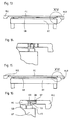
- Fig. 3 is the holding device HE1 as a section along III - III of Fig. 2 shown.
- a holding element HB is sketched here in an intermediate position between the extended position and complete engagement in the cylindrical engagement region of the opening GB.
- the opening has at its the retaining strip HLL opposite end an expansion ER on, which is open at the bottom.
- the lower boundary plane UE of the mold insert in the region of the mold cavity is lower than the lower surface of the terminal region ABL.
- the surface of the mold insert is in the example outlined in an upper boundary plane OE from the region of the mold cavities on the connection area ABL continuous, but may also be stepped or have a cover plate or a rail for a filling carriage in a conventional manner.
- the height of the mold insert between the upper and lower boundary of the mold cavities is denoted by EH.
- connection area ABL is also still a counter-clamping element GS a clamping device indicated.
- Fig. 2 Positions of several such counter-clamping elements GS are indicated in the connection areas.
- Fig. 4 shows a section through the holding device HE2 along IV - IV of Fig. 2 , From this view, the preferred circular symmetric cross section of holding element HB and opening GB can be seen as well as the advantageous extension of the expansion ER also down.
- Fig. 5 shows the holding device HE3 as a cutout V from Fig. 2 in partially cutaway view.
- the widening ER is approximately half a truncated cone in the sketched example.
- the mold insert is, as already Fig. 1 designed to be clamped by releasable clamping devices against the vibratory pad to prevent uncontrolled lifting of the mold insert from the vibrating table RT and the stone board SB during the shaking process.
- the clamping devices comprise clamping elements SE on the side of the vibrating table in lateral areas SSL, SSR and counter-clamping elements on the side of the mold insert, preferably on the underside of the connection areas ABL, ABR, which can detachably mesh with each other and can apply a high vertical clamping force between vibrating table and mold insert.
- Fig. 6 to Fig. 8 is outlined a preferred embodiment of clamping elements.
- the sketched clamping element contains in particular a about a vertical screw axis SA rotatable clamping screw SS, which is supported on the vibrating table against tensile forces upwards.
- the clamping screw engages with its screw thread SG in a mating thread GG as a counter-clamping element in the mold insert FE, preferably in a connection area ABL, ABR as to Fig. 1 to Fig. 5 already explained, and clamped when tightening the threaded connection mold insert and vibrating vertically against each other.
- the turning of the clamping screw is preferably carried out by a motor MO.
- the clamping screw S is supported with its screw head SK on the sleeve HS and guided with its shaft through the sleeve upwards.
- a drive shaft MW of the engine engages, z. B. a polygon, in the sketch to Fig. 8 a square cross-section in the screw head SK, so that rotation of the screw and rotation of the motor shaft are coupled.
- the motor shaft is only inserted in the screw head, so that in case of a defect or wear components of the clamping element can be replaced individually.
- Motor MO and sleeve HS are connected in the example outlined on more screws ST and kept at a defined distance.
- the sleeve HS can be inserted into the vibrating table from below and / or be welded into the vibrating table.
- the structure of the sleeve HS can be formed even without the sleeve as a separate component in the table body of the vibrating table itself.
- the clamping screw SS against a restoring force in the direction of placement of the mold insert on the vibrating table ie be displaced in the z-direction.
- a restoring force is in the example of FIGS. 7 to 9 applied by a compression spring VS.
- the displaceability against the restoring force allows the placement of the mold insert on the vibrating table RT or the stone board SB before the clamping screw SS is screwed with its screw thread into a counter thread GG as a counter-clamping element on the side of the mold insert.
- the clamping screw is then at its upper end under the action of the restoring force of the spring VS at the entrance of the counter thread GG, which in Fig. 7 in the bottom of a connection region ABR of a mold insert FE is indicated.
- the seat WA in the screw head for the drive shaft MW of the motor in the z-direction is sufficiently deep to allow immersion of the end of the driving motor shaft MW in the recording upon displacement of the screw down.
- the support of the clamping screw SS in the sleeve against vertical tensile forces advantageously takes place via conical bearing surfaces AF of the sleeve and the screw head, whereby any incidental dirt particles along the sloping surfaces fail down.
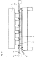
- a mold insert with retaining strips and a vibratory pad are shown at several stages of a manufacturing cycle in a molding machine, with overall side views and enlarged details shown.
- the vibrator device, the vertical guide of the retaining strips, the load-bearing device and other assemblies of the molding machine are not shown.
- Fig. 9 the mold insert FE is held with engaged holding means in the retaining strips HLL, HLR of the mold insert and vertically spaced from the Haittelunterlage with vibrating table RT and stone board SB.
- the in Fig. 10 enlarged cutout X out Fig. 9 shows that a holding element HB engages from the retaining strip HLR via the gap SP in the counter-holding element in the connection area ABR of the mold insert.
- the clamping elements SE on the side of the vibrating table are not in contact with the counter-clamping elements of the mold insert.
- the clamping screw SS is pressed by the restoring force of the spring VS in the clamping element in its upper position in the connected to the vibrating table sleeve HS.
- the holding element HB is still in engagement with the counter-holding element in the mold insert, but in this position, in the ideal case substantially free of stress, since the weight of the mold insert now rests on the stone board SB.
- the actuation of the clamping devices can advantageously be carried out in two stages, wherein in a first stage, all clamping screws are screwed with low torque in the mating thread and in a second stage tightening the screws with high torque to achieve a strong vertical tension.
- the high torque tightening in the second stage may occur before or even after release of the retainers.
- the mold insert together with the vibrating table and the stone board, performs vibrating movements relative to the holding frame fixed in the molding machine.
- the pressure plates of the loader further lower in the degree of compaction of the concrete in the mold cavities.
- the mold insert can now by moving the holding frame up in the in Fig. 21 shown position are lifted from the stone board, but with the load device AL drawn here is not lifted and the pressure plates DP hold the compacted concrete moldings BK on the stone board, so that when lifting the mold insert FE the concrete moldings BK are removed from the mold cavities.
- the clamping screws are pressed by the restoring forces of the springs back in the sleeves in their upper position.
- the vertical position of the holding frame and the mold insert must be maintained relatively accurately, so that the concrete moldings are reliably expressed from the mold cavities, but the printing plates still remain in the mold cavities.
- the vertical movement of the mold insert relative to vibrating table and / or Auflastvoriques can also be done in fixed in the molding machine holding frame and vertical movements of vibrating table or Auflastvorses.
- the operation of the holding frame and the Auflastvoriques in the molding machine, the operation of the holding devices and the clamping devices and the vibrator and the coordinated control optionally further operations within a cycle is advantageously carried out automatically or partially automatically by a control unit of the molding machine with manual triggering of individual cycle steps.
- a control unit of the molding machine with manual triggering of individual cycle steps.
- sensors can be provided for the current position of holding elements and / or clamping elements or of corresponding additional elements.
- the functions of the exemplary described holding devices which secure the mold insert in all directions in a defined position relative to the holding frame can also be divided on the vertical position of the holding frame and mold insert coupling support elements without centering on the one hand and the horizontal position of the mold insert relative to the support frame in an xy plane determining centering on the other hand, which are actuated simultaneously or successively.
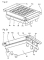
- Fig. 22 is in an oblique view from above and in Fig. 23 sketched from below a combination of support frame, mold insert and vibrating table with stone board, in which the mold insert has a much greater height between the lower and upper boundary plane of the stone field with the mold cavities.
- the handling of this mold insert is carried out substantially the same as in the preceding examples described in detail, but here are formed on the mold insert counter-holding elements in the z-direction clearly spaced from the counter-clamping elements.
- the position of the counter-holding elements and the counter-clamping elements in the x- and ⁇ -directions is substantially the same for all the different shapes, and the relative vertical Position DG of the counter-clamping elements for all different shapes in the z-direction with respect to the lower boundary plane UE of the mold inserts is the same.
- the position DH of the counter-holding elements in the z-direction with respect to the upper boundary plane OE for all mold inserts is the same.
- the mentioned relative position sizes in the z-direction are in Fig. 25 on an enlarged section from the sectional view Fig.
- mold insert FE whose arbitrary height HEV is indicated by the horizontal interruption illustrated.
- the mold inserts of different heights can then be used particularly advantageously with the same holding frame with holding elements and the same vibrating table with clamping elements, and show without further structures in each case a uniform upper side with the upper boundary plane OE
- connection area below an upper plate portion AP in which the counter-holding elements are indicated, compared to a solid block shape to the arranged on the underside of the mold insert counter-clamping elements larger recesses AA exhibit.
- the counter-clamping elements are in the example of FIGS. 22 and 23 arranged on the undersides of material webs MS.
- Fig. 26 is outlined in oblique view a combination of a mold insert with this surrounding on all four sides closed support frame HR.
- additional centering between vibrating and mold insert may be provided which are provided when placing the mold insert, which at Placing the mold insert on the vibrating table or during clamping by means of the clamping devices engage and in addition to the high-strength Fixing the mold insert on the vibrating table in the xy plane still cause a positive position securing.
- FIGS. 22 to 25 in the case of higher mold inserts in a preferred embodiment, it is assumed that the holding devices between the machine-side holding frame and the mold insert lie in the defined upper level DH of the mold insert DH and thus always without additional structure a constant upper limit over which the filling carriage is guided given is, may be given in another embodiment, a certain constant altitude between the holding devices and the lower boundary plane UE of the mold insert.
- Such a design is far more adapted to conventional molding machines, as they usually proceed with a machine-side clamping bar for receiving a flange of an interchangeable mold for placing the mold insert on the stone board or the vibrating table, the clamping bar up to a fixed stop in the machine down.
- Fig. 27 is from diagonally above and in Fig. 28 sketched obliquely from below a mold insert, wherein at the bottom of a base plate GP as connection area the stone field with the several mold star laterally surmounted and contains both the counter holding elements of the holding devices in the form of holes GB with extensions ER and the counter-clamping elements in the form of mating thread GG.
- the area of the stone field is widened laterally by a cover plate HP.
- the outer edges of the cover plate form connecting edges AKM for machine-side supports or guide plates, which are arranged on several sides adjacent to the cover plate during the filling process.
- the cover plate HP is supported by gussets KN, which are attached to side surfaces of the insert and preferably extend to the base plate GP.
- Fig. 29 is such a mold insert FEL at any height HEL in side view and in Fig. 30 an enlarged section XXX out of it sketched.
- the counter holding elements GB are arranged in a relative height position DHL which is the same for all mold inserts with respect to the lower boundary plane UE of the mold insert.
- the position of the counter holding elements is defined by a defined line of the counter holding elements, for. B. represents the center axis of a hole.
- Fig. 31 an advantageous possibility of supplementing existing molding machines is sketched to a device according to the invention.
- Conventional molding machines each have on both sides of a receiving space for a mold or a mold insert a machine flange MF with a predetermined connection pattern for a mold.
- the shape in turn has on opposite sides depending on a flange in the machine flange corresponding design.
- the machine flanges MF are each provided with a retaining strip HL, which in the sense of the present invention have machine-side holding elements HB of the holding devices between the forming frame and the mold insert.
- the retaining strips HL can be permanently connected to the machine flanges for use with several different inserts, e.g. B. bolted or welded, or clamped on the type of common form flanges only on the machine flanges and each be interchangeable with the mold insert.
- Fig. 32 is a device after Fig. 31 with inserted mold insert outlined. Connections for actuating the retaining elements HB, in particular pressure medium connections and lines are preferably provided exclusively in the retaining strips HL.
Description
Die Erfindung betrifft eine Vorrichtung zur Herstellung von Betonformsteinen durch Verdichten von Frischbeton in einer Formmaschine unter Einwirkung von Rüttelkräften.The invention relates to an apparatus for the production of concrete blocks by compacting fresh concrete in a molding machine under the action of shaking forces.
Eine derartige Vorrichtung ist beispielsweise in der
Aus der
Aus der
Die
Bei einer aus der
Der Erfindung liegt die Aufgabe zugrunde, eine vorteilhafte Vorrichtung zur Herstellung von Betonformsteinen anzugeben.The invention has for its object to provide an advantageous device for the production of concrete blocks.
Die Erfindung ist im Patentanspruch 1 beschrieben. Die abhängigen Ansprüche enthalten vorteilhafte Ausgestaltungen und Weiterbildungen der Erfindung.The invention is described in
Durch die Kombination einer lösbaren Spanneinrichtung zwischen Formeinsatz und rüttelbarer Unterlage einerseits und einer lösbaren Halteeinrichtung zwischen einem maschinenseitigen Halterahmen und dem Formeinsatz andererseits ergibt sich eine vorteilhafte funktionale Trennung unterschiedlicher Verbindungen des Formeinsatzes in unterschiedlichen Zeitabschnitten der aufeinanderfolgenden Fertigungszyklen. Insbesondere von Vorteil ist die Möglichkeit der losen Kopplung oder vorzugsweise der vollständigen Entkopplung des Formeinsatzes vom Halterahmen in der Rüttelphase. Insbesondere werden keine vertikalen Anpresskräfte zwischen Halterahmen und Formeinsatz übertragen. Andererseits ist der Formeinsatz zwischen zwei Rüttelvorgängen in der Eingriffsstellung der Halteeinrichtungen über diese mit dem Halterahmen, insbesondere auch dessen vertikaler Beweglichkeit relativ zu der rüttelbaren Unterlage so starr gekoppelt, dass ein passgenaues Eintauchen einer Druckplatte einer Auflastvorrichtung in das wenigstens eine Formnest und die präzise vertikale Position von Druckplatten und Unterkante des Formnestes beim Entformen zuverlässig gewährleistet sind. Der Einsatz ist dadurch wie ein herkömmlicher Formeinsatz beim Befüllen und Entformen handhabbar. In der Lösestellung der Halteeinrichtungen ist die Kraftkopplung zwischen Halterahmen und Formeinsatz über die Halteeinrichtung vorzugsweise vollständig aufgehoben oder so stark reduziert, dass beim Rüttelvorgang die Halterahmen messbare Beschleunigung maximal 20 %, insbesondere maximal 10 % der Beschleunigung am über die Halteeinrichtungen verbundenen Teil des Formeinsatzes beträgt.The combination of a releasable clamping device between mold insert and vibratory pad on the one hand and a releasable holding device between a machine-side support frame and the mold insert on the other hand results in an advantageous functional separation of different compounds of the mold insert in different periods of successive manufacturing cycles. Of particular advantage is the possibility of loose coupling or preferably complete decoupling of the mold insert from the holding frame in the vibrating phase. In particular, no vertical contact forces between holding frame and mold insert are transmitted. On the other hand, the mold insert between two shaking in the engaged position of the holding devices on this with the holding frame, in particular its vertical mobility relative to the vibratory pad so rigidly coupled that a precise immersion of a pressure plate Auflastvorrichtung in the at least one mold cavity and the precise vertical position are reliably ensured by printing plates and bottom edge of the mold cavity during demolding. The insert is thus manageable as a conventional mold insert during filling and demolding. In the release position of the holding devices, the power coupling between the holding frame and mold insert on the holding device is preferably completely canceled or greatly reduced so that during the vibration process, the holding frame measurable acceleration maximum 20%, in particular maximum 10% of the acceleration on the holding means connected part of the mold insert.
Die Halteeinrichtungen und Spanneinrichtungen sind automatisch, insbesondere über ein Druckfluid, vorzugsweise hydraulisch betätigbar. Vorzugsweise steuert eine Steuereinrichtung in Koordination mit anderen Betätigungselementen der Formmaschine die zeitrichtige Betätigung der Halteeinrichtungen und Spanneinrichtungen.The holding devices and clamping devices are automatically, in particular via a pressurized fluid, preferably hydraulically actuated. Preferably, a control device in coordination with other actuators of the molding machine controls the timely operation of the holding devices and clamping devices.
Hinsichtlich der Art der Rüttelanregung bestehen keine Einschränkungen, insbesondere kann auch die Schockvibration mit Schlagleisten zum Einsatz kommen. Eine Rütteleinrichtung mit Schwingungserregern zwischen der Unterlage und einer Gegenmasse weist vorteilhaft eine gegenüber dem Formeinsatz große Gegenmasse auf.With regard to the type of Rüttelanregung there are no restrictions, in particular, the shock vibration can be used with blow bars. A vibrating device with vibration exciters between the base and a counterweight advantageously has a counterweight to the mold insert on the opposite.
Die Halteeinrichtungen weisen vorteilhafterweise auf Seiten des mit der Formmaschine verbunden Halterahmens bewegliche, vorzugsweise automatisch betätigbare Halteelemente und auf Seiten des Formeinsatzes nur passive Gegenelemente zum lösbaren Eingriff mit den Halteelementen auf. Die passiven Gegenelemente können insbesondere Öffnungen in dem Formeinsatz sein, in welche die Halteelemente eingeführt werden können.The holding devices advantageously have movable, preferably automatic, sides of the holding frame connected to the forming machine operable holding elements and on the side of the mold insert only passive counter-elements for releasable engagement with the holding elements. The passive counter-elements may in particular be openings in the mold insert into which the holding elements can be inserted.
Die Halteelemente sind dabei in vorteilhafter Ausführung zumindest an ihren dem Formeinsatz zugewandten Ende bolzenförmig ausgeführt. Die Öffnung im Formeinsatz ist vorteilhafterweise auf den den Halterahmen abgewandten Ende eines Bereichs für den Eingriff der Halteelemente aufgeweitet und nach unten offen. Hierdurch kann Frischbeton, welcher u. U. in den Bereich der Öffnungen gelangt ist, zu der Aufweitung hin verschoben werden und nach unten ausfallen.The holding elements are designed in an advantageous embodiment at least at their end facing the mold insert bolt-shaped. The opening in the mold insert is advantageously expanded on the holding frame facing away from the end of a region for the engagement of the holding elements and open at the bottom. As a result, fresh concrete, which u. U. in the area of the openings has been moved to the widening and fail down.
In anderer vorteilhafter Ausführung sind die Halteeinrichtungen zwischen der Lösestellung und der Eingriffsstellung im wesentlichen unbeweglich und enthalten Halteelemente, deren Kraftkopplung zwischen Halterahmen und Formeinsatz veränderlich ist. In einer bevorzugten Ausbildung enthalten die Halteelemente fluidgefüllte Hohlkörper, deren Kraftkopplung durch Veränderung des Fluiddruckes über Zuleitungen zu den Hohlkörpern einstellbar ist. Für die starre Kopplung in der Eingriffsstellung werden die Hohlkörper mit hohem Fluiddruck beaufschlagt, für die Lösestellung werden die Hohlkörper mit geringem Druck beaufschlagt oder drucklos geschaltet und dadurch weich im Koppelverhalten. In anderer Ausbildung können die Halteelemente Magnetspulen enthalten, welche Magnetfelder für die Eingriffsstellung erzeugen, insbesondere abstoßend wirkende Magnetfelder, wobei vorzugsweise auf Seiten des Formeinsatzes Permanentmagnete angeordnet sind.In another advantageous embodiment, the holding devices between the release position and the engagement position are substantially immovable and contain holding elements whose power coupling between the holding frame and mold insert is variable. In a preferred embodiment, the holding elements contain fluid-filled hollow body whose force coupling is adjustable by changing the fluid pressure via leads to the hollow bodies. For the rigid coupling in the engaged position, the hollow body are subjected to high fluid pressure, for the release position, the hollow body are subjected to low pressure or switched without pressure and thus soft in the coupling behavior. In another embodiment, the holding elements may contain magnetic coils which generate magnetic fields for the engagement position, in particular repulsive magnetic fields, wherein preferably on the side of the mold insert permanent magnets are arranged.
Die weitgehende Entkopplung des Halterahmens vom Formeinsatz während des Rüttelvorgangs, insbesondere der Wegfall der vertikalen Anpresskräfte zwischen Halterahmen und Formeinsatz vereinfacht auch wesentlich die Befestigung eines in der Formmaschine vertikal verfahrbaren und während der Rüttelvorgang feststehenden Halterahmens.The extensive decoupling of the holding frame from the mold insert during the shaking process, in particular the elimination of the vertical contact forces between the holding frame and mold insert also significantly simplifies the attachment a vertically movable in the molding machine and fixed during the shaking holding frame.
Der Halterahmen besteht vorteilhafterweise aus lediglich zwei an gegenüberliegenden Seiten des Formeinsatzes angeordneten und einzeln mit der Formmaschine verbundenen Halteflanschen oder Halteleisten. Der Halterahmen kann aber in anderer Ausführung auch den Formeinsatz als U-Form an drei oder geschlossen an allen vier Seiten umgeben.The holding frame is advantageously made of only two arranged on opposite sides of the mold insert and individually connected to the molding machine retaining flanges or retaining strips. The support frame but in other embodiments, the mold insert as a U-shape to three or closed on all four sides surrounded.
Die Halteelemente halten den Formeinsatz in einer horizontalen Ebene vorteilhafterweise in einer definierten Position, so dass keine weiteren Zentrierelemente zur genauen Ausrichtung von Formeinsatz und Druckplatten einer Auflastvorrichtung notwendig sind. Die Halteelemente tragen den Formeinsatz in von der Rüttelunterlage abgehobener Position, insbesondere bei der Entformung der verdichteten Betonformkörper aus dem Formeinsatz.The holding elements hold the mold insert in a horizontal plane advantageously in a defined position, so that no further centering for precise alignment of mold insert and printing plates of a Auflastvorrichtung are necessary. The holding elements support the mold insert in a position lifted from the vibrating support, in particular during the demolding of the compacted concrete moldings from the mold insert.
Spannelemente der Spanneinrichtungen greifen vorteilhafterweise von unten in den Formeinsatz in Gegenelemente ein, insbesondere in nach unten offene und vorzugsweise nach oben gegen das Einfallen von Frischbeton geschlossene Öffnungen in der Unterseite des Formeinsatzes. Spannelemente und Gegenspannelemente sind vorteilhafterweise relativ zueinander verdrehbar ausgeführt. Anlageflächen zur Verspannung der Spanneinrichtungen können dann vorteilhafterweise zumindest annähernd als Wendelabschnitte um die Drehachse von Spannelement bzw. Gegenspannelement ausgebildet sein. In bevorzugter Ausführung greifen die Spannelemente und Gegenspannelemente über ein Gewinde ineinander.Clamping elements of the clamping devices engage advantageously from below into the mold insert in counter-elements, in particular in downwardly open and preferably closed up against the incidence of fresh concrete openings in the bottom of the mold insert. Clamping elements and counter-clamping elements are advantageously designed to rotate relative to each other. Contact surfaces for clamping the clamping devices can then advantageously be formed at least approximately as helical sections about the axis of rotation of clamping element or counter-clamping element. In a preferred embodiment, the clamping elements and counter-clamping elements engage in one another via a thread.
Die Spanneinrichtungen verspannen für den Rüttelvorgang den Formeinsatz gegen die Unterlage mit einer Kraft, welche typischerweise auch ausreicht, um ein seitliches Verschieben des vom Rahmen entkoppelten Formeinsatzes auf der Unterlage zuverlässig zu verhindern. Zusätzlich können zwischen Rüttelunterlage und Formeinsatz Zentrierelemente vorgesehen sein, welche bei auf der Rüttelunterlage aufgesetztem Formeinsatz mit Strukturen und Gegenstrukturen formschlüssig ineinander eingreifen und die Position des Formeinsatzes auf der Rüttelunterlage bestimmen und gegen horizontale Verschiebung des Formeinsatzes relativ zu der Unterlage sichern. Zwischen den metallischen Formeinsatz und die typischerweise gleichfalls metallische Rüttelunterlage kann in an sich bekannter Weise eine Zwischenlage, üblicherweise in Form eines Holzbretts, eingefügt sein, welche vor allem für die Ein-Lagen-Fertigung auch als Unterlage für den Abtransport und die Zwischenlagerung der Betonformkörper dient.The clamping devices brace for the shaking the mold insert against the pad with a force which is typically sufficient to to reliably prevent a lateral displacement of the decoupled from the frame mold insert on the pad. In addition, centering elements can be provided between the vibrating pad and the mold insert, which engage positively with one another on the vibrating pad mold insert with structures and counter-structures and determine the position of the mold insert on the vibrating pad and secure against horizontal displacement of the mold insert relative to the pad. Between the metallic mold insert and the typically also metallic Rüttelunterlage can be inserted in a conventional manner, an intermediate layer, usually in the form of a wooden board, which serves mainly for the one-layer production as a support for the removal and storage of the concrete moldings ,
Die Erfindung ist nachfolgend anhand bevorzugter Ausführungsbeispiele unter Bezugnahme auf die Abbildungen noch eingehend veranschaulicht. Dabei zeigt:
- Fig. 1
- einen Formeinsatz von einer Rüttelunterlage abgehoben,
- Fig. 2
- eine Draufsicht auf Formeinsatz mit Halterahmen,
- Fig. 3
- einen vergrößerten Schnitt entlang III - III von
Fig. 2 , - Fig. 4
- einen vergrößerten Schnitt entlang IV- IV von
Fig. 2 , - Fig. 5
- den Ausschnitt V von
Fig. 2 vergrößert, - Fig. 6
- eine bevorzugte Ausführung eines Spannelements,
- Fig. 7
- das Spannelement nach
Fig. 6 in teilweise geschnittener Seitenansicht, - Fig. 8
- einen Schnitt entlang VIII - VIII von
Fig. 7 , - Fig. 9 bis 21
- eine Betätigungs-Abfolge für Halteeinrichtungen und Spanneinrichtungen,
- Fig. 22
- eine Schrägansicht eines Formeinsatzes für größere Steinhöhen auf einer Rüttelunterlage,
- Fig. 23
- die Anordnung von
Fig. 21 von schräg unten, - Fig. 24
- einen Schnitt durch eine Anordnung nach
Fig. 22 , - Fig. 25
- einen Ausschnitt XXV aus
Fig. 24 , - Fig. 26
- einen um einen Formeinsatz geschlossenen Halterahmen,
- Fig. 27
- einen hohen Formeinsatz mit Halteeinrichtungen im unteren Bereich,
- Fig. 28
- den Formeinsatz nach
Fig. 27 von schräg unten, - Fig. 29
- eine Maschinennachrüstung mit Hilfs-Halterahmen,
- Fig. 30
- die Anordnung nach
Fig. 29 mit einem Formeinsatz nachFig. 27 , - Fig. 31
- ein Beispiel mit fluidgefüllten Hohlkörpern in den Halteeinrichtungen,
- Fig. 32
- ein Beispiel mit Magnetspulen in den Halteeinrichtungen.
- Fig. 1
- lifted a mold insert from a shaker pad,
- Fig. 2
- a plan view of mold insert with holding frame,
- Fig. 3
- an enlarged section along III - III of
Fig. 2 . - Fig. 4
- an enlarged section along IV- IV of
Fig. 2 . - Fig. 5
- the section V of
Fig. 2 increased - Fig. 6
- a preferred embodiment of a clamping element,
- Fig. 7
- the clamping element after
Fig. 6 in a partially sectioned side view, - Fig. 8
- a section along VIII - VIII of
Fig. 7 . - Fig. 9 to 21
- an actuating sequence for holding devices and clamping devices,
- Fig. 22
- an oblique view of a mold insert for larger stone heights on a Rüttelunterlage,
- Fig. 23
- the arrangement of
Fig. 21 from diagonally below, - Fig. 24
- a section through an arrangement after
Fig. 22 . - Fig. 25
- a section XXV
Fig. 24 . - Fig. 26
- a holding frame closed around a mold insert,
- Fig. 27
- a high mold insert with holding devices in the lower area,
- Fig. 28
- the mold insert after
Fig. 27 from diagonally below, - Fig. 29
- a machine retrofit with auxiliary support frame,
- Fig. 30
- the arrangement after
Fig. 29 with a mold insert afterFig. 27 . - Fig. 31
- an example with fluid-filled hollow bodies in the holding devices,
- Fig. 32
- an example with magnetic coils in the holding devices.
Der Halterahmen besteht im skizzierten bevorzugten Beispiel aus zwei in horizontaler γ-Richtung des mit eingezeichneten Koordinatensystems an gegenüberliegenden Seiten des Formeinsatzes FE angeordneten Halteleisten HLL, HLR. Die Halteleisten sind dauerhaft mit der Maschine verbunden und zur Aufnahme verschiedener austauschbarer Formeinsätze vorgesehen. Die Halteleisten sind in für Halterahmen an sich gebräuchlicher Weise mittels Hydraulikzylindern vertikal verfahrbar und dabei in Vertikalführungen, welche auch durch die Hydraulikzylinder selbst gebildet sein können, geführt. Von der Formmaschine sind der Übersichtlichkeit halber nur die Vertikalführungen eingezeichnet. Der Formeinsatz weist in einem mittleren Bereich ein Steinfeld mit mehreren Formnestern FN auf, welche nach oben und unten offene Aufnahmen für Frischbeton oder ein ähnliches Gemenge bilden. Die Formnester bestimmen wesentlich die Gestalt der auf dem Formeinsatz hergestellten Betonformkörper. Seitlich des Formnester-Bereichs zu den Halteleisten HLL, HLR hin weist der Formeinsatz Anschlussbereiche ABL bzw. ABR auf, welche in skizziertem Beispiel bis auf einen schmalen Spalt SP an die zugeordneten Halteleisten heranreichen. In den Anschlussbereichen sind Gegenhalteelemente zu Halteeinrichtungen zwischen Halteleisten und Formeinsatz sowie Gegenspannelemente von Spanneinrichtungen zum vertikalen Verspannen des Formeinsatzes gegen die Rüttelunterlage angeordnet, welche nachfolgend noch anhand vorteilhafter Ausführungsformen veranschaulicht sind. Die in Eingriffsstellung befindlichen Halteeinrichtungen bestimmen die horizontale Position des Formeinsatzes bezüglich der Halteleisten und koppeln den Formeinsatz an die vertikale Verschiebung der Halteleisten entlang der Vertikalführungen.The support frame consists in the preferred example outlined of two arranged in the horizontal γ-direction of the marked coordinate system on opposite sides of the mold insert FE retaining strips HLL, HLR. The retaining strips are permanently connected to the machine and provided for receiving various interchangeable mold inserts. The retaining strips are vertically movable in a conventional manner for holding frame by means of hydraulic cylinders and guided in vertical guides, which may also be formed by the hydraulic cylinder itself. For reasons of clarity, only the vertical guides are indicated by the molding machine. The mold insert has in a central region a stone field with a plurality of mold cavities FN, which form up and down open receptacles for fresh concrete or a similar mixture. The mold cavities essentially determine the shape of the concrete moldings produced on the mold insert. At the side of the cavity area to the retaining strips HLL, HLR out, the mold insert on connection areas ABL and ABR, which in sketched example zoom up to a narrow gap SP to the associated retaining strips. In the connection areas counter holding elements are arranged to holding devices between retaining strips and mold insert and counter-clamping elements of clamping devices for vertical clamping of the mold insert against the Rüttelunterlage, which hereinafter with reference to advantageous Embodiments are illustrated. The engaged holding means determine the horizontal position of the mold insert with respect to the retaining strips and couple the mold insert to the vertical displacement of the retaining strips along the vertical guides.
Die rüttelbare Unterlage ist im skizzierten Beispiel als rechteckiger Rütteltisch RT dargestellt, welcher über nur schematisch angedeutete Rütteleinrichtungen RE zu Vibrationen anregbar ist, wobei die Vibrationen vorzugsweise überwiegend vertikale Komponenten aufweisen. Zur Anregung der Vibrationen können dem Fachmann an sich bekannte Rütteleinrichtungen, insbesondere auch aus dem eingangs genannten Stand der Technik entnehmbare Rütteleinrichtungen mit harmonischer Unwuchtrüttelung oder Schockvibration über Schlagleisten dienen. Die Amplituden der angeregten Vibrationen des Rütteltisches liegen typischerweise in einem Bereich zwischen 0,5 mm und 5 mm.The vibratory pad is shown in the example sketched as a rectangular vibrating table RT, which can be excited to vibrations only schematically indicated vibrators RE, the vibrations preferably have predominantly vertical components. In order to stimulate the vibrations, vibrating devices which are known per se to the person skilled in the art, in particular vibratory devices which can be removed from the aforementioned prior art, can be used with harmonic unbalance vibration or shock vibration via blow bars. The amplitudes of the excited vibrations of the vibrating table are typically in a range between 0.5 mm and 5 mm.
Auf der dem Formeinsatz zugewandten Oberseite des Rütteltisches ist in gebräuchlicher Weise ein Steinbrett SB, welches typischerweise aus Holz oder Kunststoff besteht, aufgelegt. Das Steinbrett SB nimmt in γ-Richtung nicht die gesamte Tischbreite des Rütteltisches RT in Anspruch. In γ-Richtung beidseitig des Steinbretts sind Seitenbereiche SSL, SSR des Rütteltisches mit Spannelementen SE von Spanneinrichtungen versehen. Die Spannelemente ragen in der skizzierten Ausführungsform über die Tischoberfläche nach oben und auch über die Tischunterseite nach unten hinaus. Die Gegenspannelemente der Spanneinrichtungen sind in den Anschlussbereichen ABL, ABR des Formeinsatzes angeordnet, vorzugsweise an dessen Unterseite. Besonders vorteilhafte Ausführungen solcher Spanneinrichtungen sind nachfolgend noch im Detail beschrieben. Das Steinbrett wird, insbesondere bei Ein-Lagen-Fertigung als Transport- und Lagerunterlage mit den verdichteten und entformten Betonformkörpern vom Rütteltisch in x-Richtung verschoben, weshalb entlang dieser Brettkante keine Spannelemente über die Tischoberfläche hinausstehen, und durch ein leeres Steinbrett ersetzt.On the mold insert facing top of the vibrating table is in a conventional manner a stone board SB, which typically consists of wood or plastic, placed. The stone board SB does not occupy the entire table width of the vibrating table RT in the γ direction. In the γ direction on both sides of the stone board, lateral areas SSL, SSR of the vibrating table are provided with clamping elements SE of clamping devices. The clamping elements protrude in the sketched embodiment on the table surface upwards and also on the underside of the table down. The counter-clamping elements of the clamping devices are arranged in the connection areas ABL, ABR of the mold insert, preferably on its underside. Particularly advantageous embodiments of such clamping devices are described below in detail. The stone board is, in particular in one-layer production as a transport and storage pad with the compacted and demolded concrete moldings from the vibrating table in the x direction shifted, which is why along this Board edge no tensioning elements over the table surface stand out, and replaced by an empty stone board.
Zusätzlich zu Rütteltisch und Formeinsatz ist typischerweise noch eine Auflastvorrichtung in der Formmaschine enthalten, welche allgemein bekannt und in
In
Die Halteeinrichtungen HE1, HE2, HE3 und HE4 sind jeweils durch ein Halteelement auf Seiten der Halteleiste und ein Gegenhalteelement auf Seiten des Formeinsatzes gebildet. In vorteilhafter Ausführung sind die Halteelemente quer zu einander an dem Spalt SP gegenüberstehenden Wandflächen von Halteleiste und Formeinsatz, vorzugsweise im wesentlichen senkrecht zu diesen Wandflächen linear verschiebbar. Die Halteelemente HB sind vorteilhafterweise zumindest an ihren dem Formeinsatz zuweisenden Enden bolzenartig mit im westlichen konstantem Querschnitt ausgeführt. Die Gegenhalteelemente im Formeinsatz umfassen insbesondere eine Öffnung, vorzugsweise als Bohrung, in der Wand des Formeinsatzes, welche geringfügig größer ist als der Querschnitt der bolzenförmigen Halteelemente. Über die lineare Verschiebbarkeit können die Halteelemente zwischen einer Eingriffsstellung mit in die Öffnungen GB ragenden Enden und einer aus der Öffnung zurückgezogenen Lösestellung verschoben werden. Die Verschiebung erfolgt über in den Halteleisten angeordnete Betätigungsmittel, welche vorzugsweise als druckmittelbetätigte Zylinder ausgeführt sind. Die horizontale Verschiebung der Halteelemente ermöglicht eine geringe Bauhöhe der Anschlussbereiche ABL, ABR und ist damit vorteilhaft geeignet auch für Formeinsätze zu geringen Steinhöhen von z. B. nur wenigen Zentimetern.The holding devices HE1, HE2, HE3 and HE4 are each formed by a holding element on the side of the retaining strip and a counter-holding element on the side of the mold insert. In an advantageous embodiment, the holding elements are transverse to each other on the gap SP opposite wall surfaces of retaining strip and mold insert, preferably substantially perpendicular to these wall surfaces linearly displaceable. The holding elements HB are advantageously bolt-like at least at their ends facing the mold insert with a western constant cross section. The counter-holding elements in the mold insert comprise in particular an opening, preferably as a bore, in the wall of the mold insert, which is slightly larger than the cross section of the bolt-shaped holding elements. Via the linear displaceability, the holding elements can be displaced between an engagement position with ends projecting into the openings GB and a release position withdrawn from the opening. The displacement takes place via arranged in the retaining strips actuating means, which are preferably designed as pressure-medium-actuated cylinder. The horizontal displacement of the holding elements allows a low overall height of the terminal areas ABL, ABR and is thus advantageously suitable for mold inserts to low heights of z. B. only a few centimeters.
Die Halteelemente HB sind in den Halteleisten und durch den Eingriff in die Öffnungen GB des Formeinsatzes auch dort gegen Verkippen um die Verschieberichtung gesichert und stabilisieren daher in der Eingriffsstellung die Position des Formeinsatzes jeweils quer zur jeweiligen Verschieberichtung. Um eine in der Zeichenebene der
Der Spalt ist vorzugsweise nur luftgefüllt. Von oben einfallender Schmutz kann nach unten ausfallen. Um zu vermeiden, dass Schmutzpartikel, welche in der Lösestellung der Halteeinrichtungen sich an Halteelementen HB und/oder Öffnungen GB anlagern, beim Wechsel zur Eingriffsstellung in die Öffnungen eingedrückt werden diese nach und nach ausfüllen, sind die Öffnungen GB an den den Halteleisten abgewandten Enden aufgeweitet. Die Aufweitungen ER sind vorteilhafterweise nach unten offen. In die Öffnung gelangende Schmutzpartikel werden dadurch bei Bewegen des Halteelements HB in die Eingriffsstellung über den Eingriffsbereich der Öffnung GB hinaus in die Aufweitung ER verschoben und fallen nach unten aus. Im Spalt können zusätzlich Anschlagelemente, vorzugsweise aus elastischem Material zur Begrenzung der Bewegung des Formeinsatzes relativ zum Halterahmen in der x-y-Ebene vorgesehen sein. Der Spalt kann in anderer Ausführung auch mit einer Dichteinrichtung zur Abdichtung gegen das Eindringen von Schmutz versehen sein, welche aber leicht verformbar sein soll und weder vertikale Haltekräfte zum Abheben des Formeinsatzes von der Rüttelunterlage noch vertikale Anpresskräfte während des Rüttelvorgangs aufzubringen hat und auch keine nennenswerten Anteile der Rüttelbewegung des Formeinsatzes auf die Halteleisten übertragen soll.The gap is preferably only air-filled. From above incident dirt can fall down. In order to avoid that dirt particles, which in the release position of the holding devices are attached to holding elements HB and / or openings GB are pressed into the openings when changing to the engagement position, these openings are gradually filled, the openings GB are widened at the ends facing away from the holding strips , The widenings ER are advantageously open at the bottom. As a result, dirt particles passing into the opening are displaced beyond the engagement area of the opening GB into the widening ER when the retaining element HB is moved into the engagement position and drop downwards. In the gap, additional stop elements, preferably made of elastic material for limiting the movement of the mold insert relative to the holding frame in the x-y plane may be provided. The gap may be provided in another embodiment with a sealing device for sealing against the ingress of dirt, but which should be easily deformable and neither vertical holding forces for lifting the mold insert of the Rüttelunterlage nor vertical contact forces during the Rüttelvorgangs has applied and no appreciable shares the shaking movement of the mold insert is to be transferred to the retaining strips.
In
Im Anschlussbereich ABL ist ferner noch ein Gegenspannelement GS einer Spanneinrichtung angedeutet. In
Der Formeinsatz ist, wie bereits zu
In
Vorteilhafterweise sind eine Führungshülse HS und der Motor MO zu einer in
Eine Antriebswelle MW des Motors greift, z. B. über einen Mehrkant-, in der Skizze nach
Motor MO und Hülse HS sind im skizzierten Beispiel über weitere Schrauben ST verbunden und in definiertem Abstand gehalten. Die Hülse HS kann in den Rütteltisch von unten eingesetzt und/oder in den Rütteltisch eingeschweißt sein. Die Struktur der Hülse HS kann auch ohne die Hülse als eigenes Bauteil im Tischkörper des Rütteltisches selbst ausgebildet sein.Motor MO and sleeve HS are connected in the example outlined on more screws ST and kept at a defined distance. The sleeve HS can be inserted into the vibrating table from below and / or be welded into the vibrating table. The structure of the sleeve HS can be formed even without the sleeve as a separate component in the table body of the vibrating table itself.
In besonders vorteilhafter Ausführung kann die Spannschraube SS entgegen einer Rückstellkraft in Richtung des Aufsetzens des Formeinsatzes auf den Rütteltisch, d. h. in z-Richtung verschiebbar sein. Eine solche Rückstellkraft ist im Beispiel der
Für die Verschiebbarkeit der Spannschraube ist die Aufnahme WA im Schraubenkopf für die Antriebswelle MW des Motors in z-Richtung hinreichend tief, um ein Eintauchen des Endes der antreibenden Motorwelle MW in die Aufnahme bei Verschiebung der Schraube nach unten zu ermöglichen.For the displaceability of the clamping screw, the seat WA in the screw head for the drive shaft MW of the motor in the z-direction is sufficiently deep to allow immersion of the end of the driving motor shaft MW in the recording upon displacement of the screw down.
Die Abstützung der Spannschraube SS in der Hülse gegen vertikale Zugkräfte erfolgt vorteilhafterweise über konische Anlageflächen AF von Hülse und Schraubenkopf, wodurch eventuell einfallende Schmutzpartikel entlang der schrägen Flächen nach unten ausfallen.The support of the clamping screw SS in the sleeve against vertical tensile forces advantageously takes place via conical bearing surfaces AF of the sleeve and the screw head, whereby any incidental dirt particles along the sloping surfaces fail down.
In
In
Beim Absenken des Formeinsatzes mit Halterahmen in Pfeilrichtungen der
Das Halteelement HB ist noch in Eingriff mit dem Gegenhalteelement im Formeinsatz, ist aber in dieser Position im Idealfall im wesentlichen belastungsfrei, da das Gewicht des Formeinsatzes nun auf dem Steinbrett SB ruht.The holding element HB is still in engagement with the counter-holding element in the mold insert, but in this position, in the ideal case substantially free of stress, since the weight of the mold insert now rests on the stone board SB.
In einem nächsten Schritt, in welchem Formeinsatz FE, Halterahmen HLL, HLR und Rütteltisch RT mit Steinbrett SB gemäss
Anschließend werden die Halteeinrichtungen bei weiter unveränderter relativer Lage von Formeinsatz FE, Halterahmen HLL, HLR und Rütteltisch RT mit Steinbrett SB nach
Die Betätigung der Spanneinrichtungen kann vorteilhafterweise in zwei Stufen erfolgen, wobei in einer ersten Stufe alle Spannschrauben mit geringem Anzugsmoment in die Gegengewinde eingedreht werden und in einer zweiten Stufe ein Anziehen der Schrauben mit hohem Moment zur Erzielung einer starken vertikalen Verspannung erfolgt. Das Anziehen mit hohem Moment in der zweiten Stufe kann vor oder auch erst nach dem Lösen der Halteeinrichtungen erfolgen.The actuation of the clamping devices can advantageously be carried out in two stages, wherein in a first stage, all clamping screws are screwed with low torque in the mating thread and in a second stage tightening the screws with high torque to achieve a strong vertical tension. The high torque tightening in the second stage may occur before or even after release of the retainers.
Die darauf folgenden Vorgänge des Befüllens der Formnester des Formeinsatzes FE mit Frischbeton, das Einfahren von Druckplatten der Auflastvorrichtung in die oberen Öffnungen der Formnester und der Rüttelvorgang mit Vibrationsanregung des Rütteltisches, während der Formeinsatz fest mit dem Rütteltisch bzw. dem Steinbrett vertikal verspannt bleibt, sind allgemein bekannt und daher nicht gesondert gezeichnet.The subsequent operations of filling the mold cavities of mold insert FE with fresh concrete, the retraction of printing plates of Auflastvorrichtung in the upper openings of the mold cavities and the vibration process with vibration excitation of the vibrating table, while the mold insert firmly clamped to the vibrating table or the stone board vertically are well known and therefore not shown separately.
Während des Rüttelvorgangs führt der Formeinsatz zusammen mit Rütteltisch und Steinbrett Rüttelbewegungen relativ zu dem in der Formmaschine fixierten Halterahmen aus. Die Druckplatten der Auflastvorrichtung senken sich in dem Maß der Verdichtung des Betons weiter in die Formnester ein.During the shaking operation, the mold insert, together with the vibrating table and the stone board, performs vibrating movements relative to the holding frame fixed in the molding machine. The pressure plates of the loader further lower in the degree of compaction of the concrete in the mold cavities.
Nach Abschluss des Rüttelvorgangs befinden sich in
Im nächsten Schritt gemäß
Die Reihenfolge des Eingreifens der Halteeinrichtungen und des Lösens der Spanneinrichtungen kann auch umgekehrt sein.The order of engagement of the retainers and release of the tensioners may also be reversed.
Der Formeinsatz kann nun durch Verfahren des Halterahmens nach oben in die in
Nach Anheben der Auflastvorrichtung in eine Position oberhalb des Formeinsatzes, Entfernen des Steinbretts mit den verdichteten Betonformkörpern und Einlegen eines leeren Steinbretts auf dem Rütteltisch ist wieder die in
Die vertikale Verfahrung des Formeinsatzes relativ zu Rütteltisch und/oder Auflastvorrichtung kann auch bei in der Formmaschine fest positioniertem Halterahmen und vertikalen Bewegungen von Rütteltisch bzw. Auflastvorrichtung erfolgen.The vertical movement of the mold insert relative to vibrating table and / or Auflastvorrichtung can also be done in fixed in the molding machine holding frame and vertical movements of vibrating table or Auflastvorrichtung.
Die Verfahrung des Halterahmens und der Auflastvorrichtung in der Formmaschine, die Betätigung der Halteeinrichtungen und der Spanneinrichtungen sowie der Rütteleinrichtung und die koordinierte Steuerung gegebenenfalls weiterer Vorgänge innerhalb eines Zyklus erfolgt vorteilhafterweise durch eine Steuereinheit der Formmaschine automatisch oder teilautomatisch mit manueller Auslösung einzelner Zyklusschritte. Gegenüber herkömmlichen Steuerungen von Formmaschinen ist insbesondere die zeitrichtige Einbindung der Betätigung von Halteeinrichtungen und Spanneinrichtungen von Bedeutung. Zur Überwachung der richtig erfolgten Betätigung aller Elemente können Sensoren für die aktuelle Position von Halteelementen und/oder von Spannelementen oder von damit korrespondierenden zusätzlichen Elementen vorgesehen sein.The operation of the holding frame and the Auflastvorrichtung in the molding machine, the operation of the holding devices and the clamping devices and the vibrator and the coordinated control optionally further operations within a cycle is advantageously carried out automatically or partially automatically by a control unit of the molding machine with manual triggering of individual cycle steps. Compared to conventional controls of molding machines in particular the timely involvement of the operation of holding devices and clamping devices is important. To monitor the correct operation of all elements sensors can be provided for the current position of holding elements and / or clamping elements or of corresponding additional elements.
Die Funktionen der beispielhaft geschilderten Halteeinrichtungen, welche den Formeinsatz in allen Richtungen in definierter Position relativ zum Halterahmen sichern, können auch aufgeteilt sein auf die Vertikalposition von Halterahmen und Formeinsatz koppelnde Tragelemente ohne Zentrierfunktion einerseits und die Horizontalposition des Formeinsatzes relativ zum Halterahmen in einer x-y-Ebene bestimmende Zentrierelemente andererseits, welche gleichzeitig oder nacheinander betätigbar sind.The functions of the exemplary described holding devices which secure the mold insert in all directions in a defined position relative to the holding frame, can also be divided on the vertical position of the holding frame and mold insert coupling support elements without centering on the one hand and the horizontal position of the mold insert relative to the support frame in an xy plane determining centering on the other hand, which are actuated simultaneously or successively.
In
Um auch bei höheren Formeinsätzen den Gewichtsanteil des Anschlussbereichs mit Gegenhalteelementen und Gegenspannelementen gering zu halten, kann der Anschlussbereich unterhalb eines oberen Plattenabschnitts AP, in welchem die Gegenhalteelemente angedeutet sind, gegenüber einer massiven Blockform bis zu den an der Unterseite des Formeinsatzes angeordneten Gegenspannelementen größere Aussparungen AA aufweisen. Die Gegenspannelemente sind in dem Beispiel der
In
Um eine seitliche Verschiebung in x- oder γ-Richtung des gegen den Rütteltisch verspannten und vom Halterahmen entkoppelten Formeinsatzes relativ zum Rütteltisch während des Rüttelvorgangs zu verhindern, können zusätzliche Zentriereinrichtungen zwischen Rütteltisch und Formeinsatz vorgesehen sein, welche beim Aufsetzen des Formeinsatzes vorgesehen sein, welche beim Aufsetzen des Formeinsatzes auf dem Rütteltisch oder beim Verspannen mittels der Spanneinrichtungen in Eingriff treten und zusätzlich zu der hohen kraftschlüssigen Festlegung des Formeinsatzes auf dem Rütteltisch in der x-y-Ebene noch eine formschlüssige Lagesicherung bewirken.In order to prevent lateral displacement in the x- or γ-direction of the clamped against the vibrating table and decoupled from the holding frame mold insert relative to the vibrating during the shaking, additional centering between vibrating and mold insert may be provided which are provided when placing the mold insert, which at Placing the mold insert on the vibrating table or during clamping by means of the clamping devices engage and in addition to the high-strength Fixing the mold insert on the vibrating table in the xy plane still cause a positive position securing.
Während in
In
In
In
In
Für die Gestaltungen der Halteeinrichtungen und der Spanneinrichtungen im Detail sind eine Mehrzahl anderer Lösungen dem Fachmann an sich geläufig und bekannt, beispielsweise Keilflächen oder Hydraulikzylinder für die Spanneinrichtungen, schwenkbare Halteelemente.For the designs of the holding devices and the clamping devices in detail, a plurality of other solutions are familiar to the person skilled in the art and known, for example, wedge surfaces or hydraulic cylinders for the clamping devices, pivotable holding elements.
Claims (21)
- Device for the production of at least one moulded concrete block by the compaction of fresh concrete in a moulding machine having a holding frame (HLL, HLR, HR) on the machine, a vibrating base (RT) and a mould insert (FE) having at least one mould cavity (FN), which frame is capable of being held on the base (RT) during a vibration process and is capable of vertical displacement relative to the base (RT) for the purpose of demoulding the, at least one, compacted moulded concrete block from the mould cavity (FN), characterized in that- clamping means (SE) for clamping the mould insert (FE) to the base (RT) and holding means (HE1, HE2, HE3, HE4) for holding the mould insert (FE) in the holding frame (HLL, HLR, HR) are provided,- holding means (HE1, HE2, HE3, HE4) and clamping means (SE) are capable of automatic actuation,- during a vibration process, the clamping means (SE) clamp the mould insert (FE) to the base (RT), and the holding means (HE1, HE2, HE3, HE4) are in a release position between the mould insert (FE) and the holding frame (HLL, HLR, HR),- for the purpose of demoulding, the clamping means (SE) are released and the holding means (HE1, HE2, HE3, HE4) are in an engagement position, and- the force coupling between the mould insert (FE) and the holding frame (HLL, HLR, HR) in the release position of the holding means (HE1, HE2, HE3, HE4) is lower than in its engagement position.
- Device according to Claim 1, characterized in that a control means controls the actuation of the holding means (HE1, HE2, HE3, HE4) and/or the clamping means (SE) in the course of a manufacturing cycle.
- Device according to Claim 1 or 2, characterized in that the holding frame exhibits at least two horizontally opposed holding rails (HLL, HLR) enclosing the mould insert between them.
- Device according to Claim 3, characterized in that the holding frame surrounds the mould insert (FE) on three sides or encloses it on all sides.
- Device according to one of Claims 1 to 4, characterized in that the holding means (HE1, HE2, HE3, HE4) hold the mould insert in all directions in a defined position relative to the holding frame (HLL, HLR, HR).
- Device according to one of Claims 1 to 5, characterized in that the holding means (HE1, HE2, HE3, HE4) contain displaceable, in particular linearly displaceable, holding elements between a holding frame (HLL, HLR, HR) and a mould insert (FE).
- Device according to Claim 6, characterized in that various holding elements (HB) are displaceable in different directions, in particular directions that are orthogonal to one another.
- Device according to one of Claims 1 to 7, characterized in that holding elements (HB) engage in holding openings (GB) in the mould insert (FE).
- Device according to Claim 8, characterized in that the openings exhibit widened areas (ER) facing away from the holding frame (HLL, HLR, HR).
- Device according to Claim 9, characterized in that the widened areas (ER) are open at the bottom.
- Device according to one of Claims 1 to 5, characterized in that the holding means (HE1, HE2, HE3, HE4) contain fixed holding elements (HB) that are variable in their force coupling.
- Device according to Claim 11, characterized in that the holding elements (HB) that are variable in their force coupling are fluid-filled cavities and, for the purpose of varying the force coupling, the fluid pressure is variable via supply lines to the cavities.
- Device according to Claim 11, characterized in that the holding elements (HB) that are variable in their force coupling contain solenoid coils.
- Device according to one of Claims 1 to 13, characterized in that the clamping means (SE) contain a clamping element (SS) that is capable of rotating.
- Device according to Claim 14, characterized in that the clamping element (SS) that is capable of rotating is arranged on the side of the vibrating base (RT) and, for the purpose of clamping, engages in a counter-clamping element (GG) on the side of the mould insert (FE).
- Device according to Claim 15, characterized in that the counter-clamping element (GG) is embodied as an opening in the underside of the mould insert (FE).
- Device according to Claim 15 or 16, characterized in that the clamping element (SS) and/or the counter-clamping element (GG) exhibit(s) a contact surface in the form of a helical section about the axis of rotation (SA) of the clamping element.
- Device according to Claim 14, characterized in that the clamping element and the counter-clamping element engage in one another by means of a thread (SG, GG).
- Device according to one of Claims 1 to 18, characterized in that the clamping element (SS) and the counter-clamping element (GG) are in contact with one another, on the side of the base (RT) and on the side of the mould insert (FE) respectively, when the mould insert is placed on the base before reaching the end position, and are capable of displacement against a restoring force in the direction of placement and, once the mould insert has been placed on the base, are in preloaded contact with one another under the effect of the restoring force.
- Device according to one of Claims 1 to 19, characterized in that centring devices are provided between the base (RT) and the mould insert (FE).
- Device according to one of Claims 1 to 20, characterized in that clamping means (SE) and/or holding means (HE1, HE2, HE3, HE4) are capable of being actuated, in particular hydraulically, by means of a pressurized fluid.
Priority Applications (1)
| Application Number | Priority Date | Filing Date | Title |
|---|---|---|---|
| PL06723846T PL1874514T3 (en) | 2005-04-16 | 2006-03-30 | Device for production of moulded concrete blocks |
Applications Claiming Priority (2)
| Application Number | Priority Date | Filing Date | Title |
|---|---|---|---|
| DE102005017669A DE102005017669A1 (en) | 2005-04-16 | 2005-04-16 | Device for producing concrete blocks |
| PCT/EP2006/002879 WO2006111253A2 (en) | 2005-04-16 | 2006-03-30 | Device for production of moulded concrete blocks |
Publications (2)
| Publication Number | Publication Date |
|---|---|
| EP1874514A2 EP1874514A2 (en) | 2008-01-09 |
| EP1874514B1 true EP1874514B1 (en) | 2012-10-03 |
Family
ID=36572358
Family Applications (1)
| Application Number | Title | Priority Date | Filing Date |
|---|---|---|---|
| EP06723846A Not-in-force EP1874514B1 (en) | 2005-04-16 | 2006-03-30 | Device for production of moulded concrete blocks |
Country Status (6)
| Country | Link |
|---|---|
| EP (1) | EP1874514B1 (en) |
| DE (1) | DE102005017669A1 (en) |
| DK (1) | DK1874514T3 (en) |
| ES (1) | ES2395302T3 (en) |
| PL (1) | PL1874514T3 (en) |
| WO (1) | WO2006111253A2 (en) |
Families Citing this family (1)
| Publication number | Priority date | Publication date | Assignee | Title |
|---|---|---|---|---|
| CN114347214A (en) * | 2021-12-08 | 2022-04-15 | 中建科工集团有限公司 | Concrete test block manufacturing device |
Family Cites Families (7)
| Publication number | Priority date | Publication date | Assignee | Title |
|---|---|---|---|---|
| FR710287A (en) * | 1930-01-27 | 1931-08-20 | Shake molding machine for compressing bricks | |
| DE951797C (en) * | 1955-01-11 | 1956-10-31 | Schlosser & Co G M B H | Stone forming machine with height-adjustable feed table |
| SU988560A1 (en) * | 1981-06-02 | 1983-01-15 | Конструкторско-Технологическое Бюро Республиканского Промышленного Объединения "Укртяжстройиндустрия" Министерства Строительства Предприятий Тяжелой Индустрии Усср | Device for securing mould on vibrating platform |
| DE19508152A1 (en) * | 1995-03-08 | 1996-09-12 | Kobra Formen & Anlagenbau Gmbh | Vibrating shape |
| WO2003092973A1 (en) * | 2002-05-03 | 2003-11-13 | Rampf Formen Gmbh | Mould for the production of moulded parts on a jolting table |
| DE20301954U1 (en) * | 2003-02-05 | 2003-04-24 | Iff Weimar | Device for shaping batches |
| DE10333743A1 (en) * | 2003-07-23 | 2005-02-10 | Kobra Formen Gmbh | Arrangement for the production of moldings |
-
2005
- 2005-04-16 DE DE102005017669A patent/DE102005017669A1/en not_active Ceased
-
2006
- 2006-03-30 DK DK06723846.9T patent/DK1874514T3/en active
- 2006-03-30 EP EP06723846A patent/EP1874514B1/en not_active Not-in-force
- 2006-03-30 WO PCT/EP2006/002879 patent/WO2006111253A2/en not_active Application Discontinuation
- 2006-03-30 ES ES06723846T patent/ES2395302T3/en active Active
- 2006-03-30 PL PL06723846T patent/PL1874514T3/en unknown
Also Published As
| Publication number | Publication date |
|---|---|
| DK1874514T3 (en) | 2013-01-02 |
| WO2006111253A2 (en) | 2006-10-26 |
| EP1874514A2 (en) | 2008-01-09 |
| WO2006111253A3 (en) | 2006-12-28 |
| ES2395302T3 (en) | 2013-02-11 |
| PL1874514T3 (en) | 2013-02-28 |
| DE102005017669A1 (en) | 2006-10-19 |
Similar Documents
| Publication | Publication Date | Title |
|---|---|---|
| EP1674226B1 (en) | Moulding device with mould and method for making concrete blocks | |
| EP0496077B1 (en) | Apparatus for making building blocks | |
| DE102007063143A1 (en) | Vibrating device for producing carbon electrodes for aluminum industry, comprises a vibrating table, which is seated on vertically arranged spring elements and carries a stage construction resting on supports, and a clamping device | |
| DE102006051045A1 (en) | Device for manufacturing elements from hardenable casting mass, preferably at building site places, has transportable container that is designed inside for regulation and withdrawal of movable equipment relevant for manufacturing of element | |
| EP1874514B1 (en) | Device for production of moulded concrete blocks | |
| DE102005054992A1 (en) | Device for producing concrete blocks | |
| EP0767034B1 (en) | Mould for making concrete elements | |
| DE19912829B4 (en) | Plant for the production of cup-shaped concrete bodies | |
| EP0896866B1 (en) | Process and device for the production of moulded articles | |
| EP2035200A2 (en) | Apparatus for producing moulded concrete bricks, mould for such an apparatus and process for producing such a mould | |
| EP2718071B1 (en) | Block molding machine and method for vertically adjusting a block molding machine | |
| DE102008000462A1 (en) | Mold for the production of concrete blocks | |
| DE112004001226B4 (en) | Vibration table for concrete casting machines and method for its production | |
| EP1874516B1 (en) | Device for production of moulded concrete blocks and mould system for application in such a device | |
| DE102011054488A1 (en) | Device for manufacturing e.g. paving stones in sequential manufacturing cycles, has load lower part connected with mold upper part, load upper part connected with machine, and control device variably controlling fluid pressures in bellows | |
| DE10044677B4 (en) | Vibrating machine for the molding of unfired anode blocks, in particular for aluminum pain flow electrolysis | |
| EP0175038A1 (en) | Method of making building blocks with at least one cavity and apparatus for carrying out this method | |
| DE102005058402A1 (en) | Apparatus for producing concrete blocks to a mold system for use in such a device | |
| DE19601352C2 (en) | Device for compacting earth-moist concrete | |
| EP1281492A1 (en) | Compaction device | |
| DE102006047543A1 (en) | Device for the mechanical production of concrete blocks and suitable vibrating device | |
| DE3342314A1 (en) | MACHINE FOR MAKING CASTING MOLDS | |
| DE102022126700A1 (en) | Method and device for producing concrete bodies which have a cavity open to at least one side surface of the concrete body, as well as corresponding concrete bodies | |
| DE19620305A1 (en) | Stone moulding machine | |
| DE2901545A1 (en) | METHOD AND DEVICE FOR PRODUCING SHAPED STONES |
Legal Events
| Date | Code | Title | Description |
|---|---|---|---|
| PUAI | Public reference made under article 153(3) epc to a published international application that has entered the european phase |
Free format text: ORIGINAL CODE: 0009012 |
|
| 17P | Request for examination filed |
Effective date: 20071116 |
|
| AK | Designated contracting states |
Kind code of ref document: A2 Designated state(s): AT BE BG CH CY CZ DE DK EE ES FI FR GB GR HU IE IS IT LI LT LU LV MC NL PL PT RO SE SI SK TR |
|
| DAX | Request for extension of the european patent (deleted) | ||
| 17Q | First examination report despatched |
Effective date: 20081230 |
|
| GRAP | Despatch of communication of intention to grant a patent |
Free format text: ORIGINAL CODE: EPIDOSNIGR1 |
|
| GRAS | Grant fee paid |
Free format text: ORIGINAL CODE: EPIDOSNIGR3 |
|
| GRAA | (expected) grant |
Free format text: ORIGINAL CODE: 0009210 |
|
| AK | Designated contracting states |
Kind code of ref document: B1 Designated state(s): AT BE BG CH CY CZ DE DK EE ES FI FR GB GR HU IE IS IT LI LT LU LV MC NL PL PT RO SE SI SK TR |
|
| REG | Reference to a national code |
Ref country code: GB Ref legal event code: FG4D Free format text: NOT ENGLISH |
|
| REG | Reference to a national code |
Ref country code: CH Ref legal event code: EP Ref country code: AT Ref legal event code: REF Ref document number: 577757 Country of ref document: AT Kind code of ref document: T Effective date: 20121015 |
|
| REG | Reference to a national code |
Ref country code: IE Ref legal event code: FG4D Free format text: LANGUAGE OF EP DOCUMENT: GERMAN |
|
| REG | Reference to a national code |
Ref country code: DE Ref legal event code: R096 Ref document number: 502006012041 Country of ref document: DE Effective date: 20121129 |
|
| REG | Reference to a national code |
Ref country code: DK Ref legal event code: T3 |
|
| REG | Reference to a national code |
Ref country code: ES Ref legal event code: FG2A Ref document number: 2395302 Country of ref document: ES Kind code of ref document: T3 Effective date: 20130211 |
|
| PG25 | Lapsed in a contracting state [announced via postgrant information from national office to epo] |
Ref country code: SI Free format text: LAPSE BECAUSE OF FAILURE TO SUBMIT A TRANSLATION OF THE DESCRIPTION OR TO PAY THE FEE WITHIN THE PRESCRIBED TIME-LIMIT Effective date: 20121003 |
|
| REG | Reference to a national code |
Ref country code: PL Ref legal event code: T3 |
|
| REG | Reference to a national code |
Ref country code: NL Ref legal event code: VDEP Effective date: 20121003 |
|
| REG | Reference to a national code |
Ref country code: LT Ref legal event code: MG4D |
|
| PG25 | Lapsed in a contracting state [announced via postgrant information from national office to epo] |
Ref country code: IS Free format text: LAPSE BECAUSE OF FAILURE TO SUBMIT A TRANSLATION OF THE DESCRIPTION OR TO PAY THE FEE WITHIN THE PRESCRIBED TIME-LIMIT Effective date: 20130203 Ref country code: SE Free format text: LAPSE BECAUSE OF FAILURE TO SUBMIT A TRANSLATION OF THE DESCRIPTION OR TO PAY THE FEE WITHIN THE PRESCRIBED TIME-LIMIT Effective date: 20121003 Ref country code: NL Free format text: LAPSE BECAUSE OF FAILURE TO SUBMIT A TRANSLATION OF THE DESCRIPTION OR TO PAY THE FEE WITHIN THE PRESCRIBED TIME-LIMIT Effective date: 20121003 Ref country code: FI Free format text: LAPSE BECAUSE OF FAILURE TO SUBMIT A TRANSLATION OF THE DESCRIPTION OR TO PAY THE FEE WITHIN THE PRESCRIBED TIME-LIMIT Effective date: 20121003 Ref country code: LT Free format text: LAPSE BECAUSE OF FAILURE TO SUBMIT A TRANSLATION OF THE DESCRIPTION OR TO PAY THE FEE WITHIN THE PRESCRIBED TIME-LIMIT Effective date: 20121003 |
|
| PG25 | Lapsed in a contracting state [announced via postgrant information from national office to epo] |
Ref country code: GR Free format text: LAPSE BECAUSE OF FAILURE TO SUBMIT A TRANSLATION OF THE DESCRIPTION OR TO PAY THE FEE WITHIN THE PRESCRIBED TIME-LIMIT Effective date: 20130104 Ref country code: LV Free format text: LAPSE BECAUSE OF FAILURE TO SUBMIT A TRANSLATION OF THE DESCRIPTION OR TO PAY THE FEE WITHIN THE PRESCRIBED TIME-LIMIT Effective date: 20121003 Ref country code: PT Free format text: LAPSE BECAUSE OF FAILURE TO SUBMIT A TRANSLATION OF THE DESCRIPTION OR TO PAY THE FEE WITHIN THE PRESCRIBED TIME-LIMIT Effective date: 20130204 Ref country code: CY Free format text: LAPSE BECAUSE OF FAILURE TO SUBMIT A TRANSLATION OF THE DESCRIPTION OR TO PAY THE FEE WITHIN THE PRESCRIBED TIME-LIMIT Effective date: 20121003 |
|
| PG25 | Lapsed in a contracting state [announced via postgrant information from national office to epo] |
Ref country code: SK Free format text: LAPSE BECAUSE OF FAILURE TO SUBMIT A TRANSLATION OF THE DESCRIPTION OR TO PAY THE FEE WITHIN THE PRESCRIBED TIME-LIMIT Effective date: 20121003 Ref country code: EE Free format text: LAPSE BECAUSE OF FAILURE TO SUBMIT A TRANSLATION OF THE DESCRIPTION OR TO PAY THE FEE WITHIN THE PRESCRIBED TIME-LIMIT Effective date: 20121003 Ref country code: CZ Free format text: LAPSE BECAUSE OF FAILURE TO SUBMIT A TRANSLATION OF THE DESCRIPTION OR TO PAY THE FEE WITHIN THE PRESCRIBED TIME-LIMIT Effective date: 20121003 Ref country code: BG Free format text: LAPSE BECAUSE OF FAILURE TO SUBMIT A TRANSLATION OF THE DESCRIPTION OR TO PAY THE FEE WITHIN THE PRESCRIBED TIME-LIMIT Effective date: 20130103 |
|
| PLBE | No opposition filed within time limit |
Free format text: ORIGINAL CODE: 0009261 |
|
| STAA | Information on the status of an ep patent application or granted ep patent |
Free format text: STATUS: NO OPPOSITION FILED WITHIN TIME LIMIT |
|
| PG25 | Lapsed in a contracting state [announced via postgrant information from national office to epo] |
Ref country code: IT Free format text: LAPSE BECAUSE OF FAILURE TO SUBMIT A TRANSLATION OF THE DESCRIPTION OR TO PAY THE FEE WITHIN THE PRESCRIBED TIME-LIMIT Effective date: 20121003 Ref country code: RO Free format text: LAPSE BECAUSE OF FAILURE TO SUBMIT A TRANSLATION OF THE DESCRIPTION OR TO PAY THE FEE WITHIN THE PRESCRIBED TIME-LIMIT Effective date: 20121003 |
|
| 26N | No opposition filed |
Effective date: 20130704 |
|
| BERE | Be: lapsed |
Owner name: KOBRA FORMEN G.M.B.H. Effective date: 20130331 |
|
| PG25 | Lapsed in a contracting state [announced via postgrant information from national office to epo] |
Ref country code: MC Free format text: LAPSE BECAUSE OF NON-PAYMENT OF DUE FEES Effective date: 20130331 |
|
| REG | Reference to a national code |
Ref country code: CH Ref legal event code: PL Ref country code: DE Ref legal event code: R097 Ref document number: 502006012041 Country of ref document: DE Effective date: 20130704 |
|
| GBPC | Gb: european patent ceased through non-payment of renewal fee |
Effective date: 20130330 |
|
| REG | Reference to a national code |
Ref country code: IE Ref legal event code: MM4A |
|
| PG25 | Lapsed in a contracting state [announced via postgrant information from national office to epo] |
Ref country code: IE Free format text: LAPSE BECAUSE OF NON-PAYMENT OF DUE FEES Effective date: 20130330 Ref country code: CH Free format text: LAPSE BECAUSE OF NON-PAYMENT OF DUE FEES Effective date: 20130331 Ref country code: BE Free format text: LAPSE BECAUSE OF NON-PAYMENT OF DUE FEES Effective date: 20130331 Ref country code: LI Free format text: LAPSE BECAUSE OF NON-PAYMENT OF DUE FEES Effective date: 20130331 Ref country code: GB Free format text: LAPSE BECAUSE OF NON-PAYMENT OF DUE FEES Effective date: 20130330 |
|
| PGFP | Annual fee paid to national office [announced via postgrant information from national office to epo] |
Ref country code: DE Payment date: 20140331 Year of fee payment: 9 Ref country code: DK Payment date: 20140325 Year of fee payment: 9 |
|
| REG | Reference to a national code |
Ref country code: AT Ref legal event code: MM01 Ref document number: 577757 Country of ref document: AT Kind code of ref document: T Effective date: 20130330 |
|
| PGFP | Annual fee paid to national office [announced via postgrant information from national office to epo] |
Ref country code: FR Payment date: 20140319 Year of fee payment: 9 Ref country code: PL Payment date: 20140319 Year of fee payment: 9 Ref country code: ES Payment date: 20140324 Year of fee payment: 9 |
|
| REG | Reference to a national code |
Ref country code: DE Ref legal event code: R082 Ref document number: 502006012041 Country of ref document: DE Representative=s name: BAUR & WEBER PATENTANWAELTE, DE |
|
| PG25 | Lapsed in a contracting state [announced via postgrant information from national office to epo] |
Ref country code: AT Free format text: LAPSE BECAUSE OF NON-PAYMENT OF DUE FEES Effective date: 20130330 |
|
| PG25 | Lapsed in a contracting state [announced via postgrant information from national office to epo] |
Ref country code: TR Free format text: LAPSE BECAUSE OF FAILURE TO SUBMIT A TRANSLATION OF THE DESCRIPTION OR TO PAY THE FEE WITHIN THE PRESCRIBED TIME-LIMIT Effective date: 20121003 |
|
| PG25 | Lapsed in a contracting state [announced via postgrant information from national office to epo] |
Ref country code: HU Free format text: LAPSE BECAUSE OF FAILURE TO SUBMIT A TRANSLATION OF THE DESCRIPTION OR TO PAY THE FEE WITHIN THE PRESCRIBED TIME-LIMIT; INVALID AB INITIO Effective date: 20060330 Ref country code: LU Free format text: LAPSE BECAUSE OF NON-PAYMENT OF DUE FEES Effective date: 20130330 |
|
| REG | Reference to a national code |
Ref country code: DE Ref legal event code: R119 Ref document number: 502006012041 Country of ref document: DE |
|
| REG | Reference to a national code |
Ref country code: DK Ref legal event code: EBP Effective date: 20150331 |
|
| REG | Reference to a national code |
Ref country code: FR Ref legal event code: ST Effective date: 20151130 |
|
| PG25 | Lapsed in a contracting state [announced via postgrant information from national office to epo] |
Ref country code: DE Free format text: LAPSE BECAUSE OF NON-PAYMENT OF DUE FEES Effective date: 20151001 |
|
| PG25 | Lapsed in a contracting state [announced via postgrant information from national office to epo] |
Ref country code: FR Free format text: LAPSE BECAUSE OF NON-PAYMENT OF DUE FEES Effective date: 20150331 |
|
| REG | Reference to a national code |
Ref country code: ES Ref legal event code: FD2A Effective date: 20160426 |
|
| PG25 | Lapsed in a contracting state [announced via postgrant information from national office to epo] |
Ref country code: DK Free format text: LAPSE BECAUSE OF NON-PAYMENT OF DUE FEES Effective date: 20150331 |
|
| PG25 | Lapsed in a contracting state [announced via postgrant information from national office to epo] |
Ref country code: PL Free format text: LAPSE BECAUSE OF NON-PAYMENT OF DUE FEES Effective date: 20150330 |
|
| PG25 | Lapsed in a contracting state [announced via postgrant information from national office to epo] |
Ref country code: ES Free format text: LAPSE BECAUSE OF NON-PAYMENT OF DUE FEES Effective date: 20150331 |