EP1870552B1 - Dispositif destiné à la commande de séquence de fermeture de portes pivotantes à deux battants - Google Patents
Dispositif destiné à la commande de séquence de fermeture de portes pivotantes à deux battants Download PDFInfo
- Publication number
- EP1870552B1 EP1870552B1 EP07110679.3A EP07110679A EP1870552B1 EP 1870552 B1 EP1870552 B1 EP 1870552B1 EP 07110679 A EP07110679 A EP 07110679A EP 1870552 B1 EP1870552 B1 EP 1870552B1
- Authority
- EP
- European Patent Office
- Prior art keywords
- controlling
- closing sequence
- sequence according
- leaf
- door
- Prior art date
- Legal status (The legal status is an assumption and is not a legal conclusion. Google has not performed a legal analysis and makes no representation as to the accuracy of the status listed.)
- Active
Links
Images

Classifications
-
- E—FIXED CONSTRUCTIONS
- E05—LOCKS; KEYS; WINDOW OR DOOR FITTINGS; SAFES
- E05F—DEVICES FOR MOVING WINGS INTO OPEN OR CLOSED POSITION; CHECKS FOR WINGS; WING FITTINGS NOT OTHERWISE PROVIDED FOR, CONCERNED WITH THE FUNCTIONING OF THE WING
- E05F5/00—Braking devices, e.g. checks; Stops; Buffers
- E05F5/12—Braking devices, e.g. checks; Stops; Buffers specially for preventing the closing of a wing before another wing has been closed
-
- E—FIXED CONSTRUCTIONS
- E05—LOCKS; KEYS; WINDOW OR DOOR FITTINGS; SAFES
- E05F—DEVICES FOR MOVING WINGS INTO OPEN OR CLOSED POSITION; CHECKS FOR WINGS; WING FITTINGS NOT OTHERWISE PROVIDED FOR, CONCERNED WITH THE FUNCTIONING OF THE WING
- E05F15/00—Power-operated mechanisms for wings
- E05F15/60—Power-operated mechanisms for wings using electrical actuators
- E05F15/603—Power-operated mechanisms for wings using electrical actuators using rotary electromotors
- E05F15/611—Power-operated mechanisms for wings using electrical actuators using rotary electromotors for swinging wings
- E05F15/63—Power-operated mechanisms for wings using electrical actuators using rotary electromotors for swinging wings operated by swinging arms
-
- E—FIXED CONSTRUCTIONS
- E05—LOCKS; KEYS; WINDOW OR DOOR FITTINGS; SAFES
- E05F—DEVICES FOR MOVING WINGS INTO OPEN OR CLOSED POSITION; CHECKS FOR WINGS; WING FITTINGS NOT OTHERWISE PROVIDED FOR, CONCERNED WITH THE FUNCTIONING OF THE WING
- E05F3/00—Closers or openers with braking devices, e.g. checks; Construction of pneumatic or liquid braking devices
- E05F3/22—Additional arrangements for closers, e.g. for holding the wing in opened or other position
- E05F3/227—Additional arrangements for closers, e.g. for holding the wing in opened or other position mounted at the top of wings, e.g. details related to closer housings, covers, end caps or rails therefor
-
- E—FIXED CONSTRUCTIONS
- E05—LOCKS; KEYS; WINDOW OR DOOR FITTINGS; SAFES
- E05Y—INDEXING SCHEME ASSOCIATED WITH SUBCLASSES E05D AND E05F, RELATING TO CONSTRUCTION ELEMENTS, ELECTRIC CONTROL, POWER SUPPLY, POWER SIGNAL OR TRANSMISSION, USER INTERFACES, MOUNTING OR COUPLING, DETAILS, ACCESSORIES, AUXILIARY OPERATIONS NOT OTHERWISE PROVIDED FOR, APPLICATION THEREOF
- E05Y2201/00—Constructional elements; Accessories therefor
- E05Y2201/40—Motors; Magnets; Springs; Weights; Accessories therefor
- E05Y2201/404—Function thereof
- E05Y2201/41—Function thereof for closing
-
- E—FIXED CONSTRUCTIONS
- E05—LOCKS; KEYS; WINDOW OR DOOR FITTINGS; SAFES
- E05Y—INDEXING SCHEME ASSOCIATED WITH SUBCLASSES E05D AND E05F, RELATING TO CONSTRUCTION ELEMENTS, ELECTRIC CONTROL, POWER SUPPLY, POWER SIGNAL OR TRANSMISSION, USER INTERFACES, MOUNTING OR COUPLING, DETAILS, ACCESSORIES, AUXILIARY OPERATIONS NOT OTHERWISE PROVIDED FOR, APPLICATION THEREOF
- E05Y2201/00—Constructional elements; Accessories therefor
- E05Y2201/40—Motors; Magnets; Springs; Weights; Accessories therefor
- E05Y2201/404—Function thereof
- E05Y2201/422—Function thereof for opening
-
- E—FIXED CONSTRUCTIONS
- E05—LOCKS; KEYS; WINDOW OR DOOR FITTINGS; SAFES
- E05Y—INDEXING SCHEME ASSOCIATED WITH SUBCLASSES E05D AND E05F, RELATING TO CONSTRUCTION ELEMENTS, ELECTRIC CONTROL, POWER SUPPLY, POWER SIGNAL OR TRANSMISSION, USER INTERFACES, MOUNTING OR COUPLING, DETAILS, ACCESSORIES, AUXILIARY OPERATIONS NOT OTHERWISE PROVIDED FOR, APPLICATION THEREOF
- E05Y2201/00—Constructional elements; Accessories therefor
- E05Y2201/40—Motors; Magnets; Springs; Weights; Accessories therefor
- E05Y2201/43—Motors
- E05Y2201/434—Electromotors; Details thereof
-
- E—FIXED CONSTRUCTIONS
- E05—LOCKS; KEYS; WINDOW OR DOOR FITTINGS; SAFES
- E05Y—INDEXING SCHEME ASSOCIATED WITH SUBCLASSES E05D AND E05F, RELATING TO CONSTRUCTION ELEMENTS, ELECTRIC CONTROL, POWER SUPPLY, POWER SIGNAL OR TRANSMISSION, USER INTERFACES, MOUNTING OR COUPLING, DETAILS, ACCESSORIES, AUXILIARY OPERATIONS NOT OTHERWISE PROVIDED FOR, APPLICATION THEREOF
- E05Y2400/00—Electronic control; Electrical power; Power supply; Power or signal transmission; User interfaces
- E05Y2400/10—Electronic control
- E05Y2400/30—Electronic control of motors
- E05Y2400/3013—Electronic control of motors during manual wing operation
- E05Y2400/3015—Power assistance
-
- E—FIXED CONSTRUCTIONS
- E05—LOCKS; KEYS; WINDOW OR DOOR FITTINGS; SAFES
- E05Y—INDEXING SCHEME ASSOCIATED WITH SUBCLASSES E05D AND E05F, RELATING TO CONSTRUCTION ELEMENTS, ELECTRIC CONTROL, POWER SUPPLY, POWER SIGNAL OR TRANSMISSION, USER INTERFACES, MOUNTING OR COUPLING, DETAILS, ACCESSORIES, AUXILIARY OPERATIONS NOT OTHERWISE PROVIDED FOR, APPLICATION THEREOF
- E05Y2400/00—Electronic control; Electrical power; Power supply; Power or signal transmission; User interfaces
- E05Y2400/10—Electronic control
- E05Y2400/30—Electronic control of motors
- E05Y2400/302—Electronic control of motors during electric motor braking
-
- E—FIXED CONSTRUCTIONS
- E05—LOCKS; KEYS; WINDOW OR DOOR FITTINGS; SAFES
- E05Y—INDEXING SCHEME ASSOCIATED WITH SUBCLASSES E05D AND E05F, RELATING TO CONSTRUCTION ELEMENTS, ELECTRIC CONTROL, POWER SUPPLY, POWER SIGNAL OR TRANSMISSION, USER INTERFACES, MOUNTING OR COUPLING, DETAILS, ACCESSORIES, AUXILIARY OPERATIONS NOT OTHERWISE PROVIDED FOR, APPLICATION THEREOF
- E05Y2800/00—Details, accessories and auxiliary operations not otherwise provided for
- E05Y2800/15—Applicability
- E05Y2800/17—Universally applicable
- E05Y2800/172—Universally applicable on different wing or frame locations
-
- E—FIXED CONSTRUCTIONS
- E05—LOCKS; KEYS; WINDOW OR DOOR FITTINGS; SAFES
- E05Y—INDEXING SCHEME ASSOCIATED WITH SUBCLASSES E05D AND E05F, RELATING TO CONSTRUCTION ELEMENTS, ELECTRIC CONTROL, POWER SUPPLY, POWER SIGNAL OR TRANSMISSION, USER INTERFACES, MOUNTING OR COUPLING, DETAILS, ACCESSORIES, AUXILIARY OPERATIONS NOT OTHERWISE PROVIDED FOR, APPLICATION THEREOF
- E05Y2900/00—Application of doors, windows, wings or fittings thereof
- E05Y2900/10—Application of doors, windows, wings or fittings thereof for buildings or parts thereof
- E05Y2900/13—Type of wing
- E05Y2900/132—Doors
Definitions
- the invention relates to a device for closing sequence control for double-leaf hinged doors according to the preamble of claim 1.
- a device for closing sequence control for double-leaf doors with an underpowering inactive leaf and a swinging active leaf known, each cooperating with fixed mounted drives, each drive having an output shaft which cooperates with an electric motor for opening and a closer unit with closing spring for closing.
- the active leaf is operatively connected to a blocking device, which is controllable in dependence on the position of the passive leaf, by a transmission member is provided, which cooperates with its one end to the blocking device and with its other end with an actuated by the inactive leaf or a connected part actuator , which is arranged in the region of the housing of the passive leaf drive.
- the blocking device acts on the motor shaft of the moving leaf drive, which is in operative connection with the output shaft of the moving leaf drive.
- the active leaf is detectable by means of a releasable from the passive leaf locking mechanism.
- the axis of rotation of the inactive leaf is provided with a cam disc, which is in operative connection via an actuating element with a brake acting on the axis of rotation of the active leaf. It is provided in the brake area formed by an overload spring overload protection.
- the brake is designed as a two-part shoe brake, which surrounds a provided on the axis of the active leaf freewheel.
- the closing sequence control interacts with the rotary axes of the door leaves and can not be used in conjunction with automatic door drives.
- WO 98/07944 A1 discloses a closing sequence control device for a two-leaf, a passive leaf and a wing comprising comprehensive door whose door is each a drive unit for the controllable opening and / or closing in conjunction with a moving the door leaf serving power transmission shaft.
- the power transmission shaft is adaptively equipped with an exclusively mechanically operating device for controlling the closing sequence, namely a first-action leaf opening first on the basis of a detector signal and a subsequently likewise opening passive leaf.
- the power wing associated drive unit can be detected and released by an operable by the inactive leaf locking member, wherein a corresponding element is connected between the drive units.
- the door leaves are provided with an electro-hydraulic door drive, wherein a blocking valve is connected in the hydraulic system of the moving leaf drive and controlled by the passive leaf drive for blocking the active leaf.
- the invention has for its object to provide a universally arranged closing sequence control.
- Closing sequence controls are required for double-leaf revolving doors when the door leaves are provided with a door rebate, with the fixed leaf with its door rebate forms the stop for the active leaf. Since the two leaves overlap in the central region, the passive leaf must always be closed first before the active leaf closes completely, since otherwise the passive leaf abuts the overlap of the active leaf and the door remains partially open, which is inadmissible especially in the case of smoke and fire doors is. Therefore, the closing sequence control has a controlled by the fixed wing locking device, which detects the active leaf in an at least partially open position with open wing, and thus allows closing of the inactive leaf in front of the active leaf.
- the device according to the invention for closing sequence control ensures that on a double-leaf, having a moving leaf and a passive leaf door equipped with door drives the undercutting passive leaf logically closes in front of the sweeping active leaf.
- the active leaf is held by a blocking device in a partially open position when the inactive leaf is open, wherein the blocking device cooperates with an actuatable by the inactive leaf triggering device.
- the door drives are arranged above the door leaf and are operatively connected via rods or slide arms, which engage with sliders in a wing fixedly arranged slide, with the respective door.
- the door drives on the hinge side, ie on the side of the doors on which the door wings are pivotally received in door hinges or door hinges, or on the corresponding opposite side of the doors, the hinge opposite side.
- the door drives are designed for motorized opening and have for actuating in the closing direction on a spring arrangement.
- a controlled electric motor and the spring arrangement acts on a gear, which cooperates with the sliding arm or linkage for wing actuation.
- the door drive for the active leaf and for the fixed leaf are constructed essentially identically.
- the gangway-side door drive in addition to a brake as a blocking device, which is arranged on the motor shaft.
- the door leaf-side door drive additionally has a triggering element, which actuates the gangway-side brake via a transmission element arranged between the door drives.
- the motor shaft of the gangway side door drive is extended into a brake housing.
- a freewheel is rotatably mounted on which a brake drum is fixed.
- the freewheel allows opening of the active leaf when the brake is locked.
- the brake drum is surrounded by a brake pad which does not completely surround the brake drum.
- the brake pad has a directed towards the brake drum bias, which can also be reinforced by one or more springs, since such friction pads usually do not have high elasticity for a sufficiently large bias.
- the free area of the annular brake pad allows the engagement of a spreading element, which is designed in the manner of an eccentric. A rotation of the expansion element causes a release of the brake by the brake pad is lifted from the brake drum.
- the rotatably mounted in the brake housing expansion element is substantially cylindrical and has in the region which is arranged between the brake pad, a non-circular contour, whereby the brake pad is pressed apart depending on the angular position of the expansion element.
- the rotation of the expansion element is effected by the stand-wing-side trigger, which is connected by a transmission element, such as a cable or a belt, with the expansion element.
- a transmission element such as a cable or a belt
- a lever or a cam can be arranged to force transmission on the expansion element, which acts on the transmission element.
- the release element arranged in the gearbox of the door leaf-side door drive is rotatably mounted on the output shaft and cooperates with a winding disk which is arranged non-rotatably on the output shaft.
- a rope or band is wound up when opening the door leaf, which tensions a closing spring supported in the spring arrangement.
- the trigger element is released, and arranged on the transition wing brake brake expander rotates by the restoring force of the brake pad and possibly also acting on these springs so that the brake pad comes into contact with the brake drum and the Motor shaft in the closing direction notes.
- the trigger element is operatively connected by the transmission element, such as a cable, with the expansion element for actuating the brake.
- the transmission element can be optionally set to two opposing pivot levers on the trigger element, which is carried out without modification to the drives the logical operation of the brake.
- opening of the active leaf is possible even when the brake is detected by the arranged on the motor shaft freewheel. Damage to the door system through improper manual operation of the detected active leaf is avoided by the brake is designed so that in case of overload, the brake pad can slip on the brake drum.
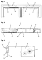
- the Fig. 1 shows a two-leaf door with a moving leaf 1 and a passive leaf 2.
- a door drive 3, 4 is arranged, which has a rotatably connected to an output shaft 10, 10 'sliding arm 13, 13' for transmitting power.
- a slider is arranged rotatably on the end facing away from the door drive 3, 4, which is guided in a guide rail 14, 14' fixed to the wing.
- a linkage of two pivotally interconnected lever arms on the output shaft 10, 10' may be arranged, wherein the linkage at the other end on the respective door 1, 2 is rotatably fixed.
- the door drives 3, 4 can be arranged on the hinge side, the side on which the door hinges are arranged, or on the opposite side, the so-called hinge opposite side.
- the door drive 3, 4 is mounted rotated by 180 ° depending on the mounting on the belt or hinge side.
- the output shaft 10, 10 ' is accessible on both sides of the transmission 8 for mounting the sliding arm 13 or the linkage.
- FIG. 2 the components of the substantially identical door drives 3, 4 are shown in a schematic diagram on the basis of the door leaf-side door drive 3.
- a drive motor 6 is connected to a not shown in the figure motor shaft 7 with a gear 8.
- the gear 8 cooperates with a spring arrangement 9, which serves as an energy store and a closing of the door 1 or 2 causes.
- a closing spring is arranged in a receiving space, wherein the closing spring is tensioned when opening the door leaf 1 or 2.
- the output shaft 10 is arranged.
- a control unit 11 for controlling the door drive 3 or 4 is provided.
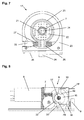
- Fig. 4 is a plan view of the low-wing door drive 4 shown, wherein the transmission is open.
- a worm is rotatably mounted, which forms a gear reducer 8 with an arrangement of gears.
- a transmission shaft is guided to the outside and forms the output shaft 10 ', at the shaft end of the sliding arm 13' is fixed.
- a winding disk 15 is rotatably disposed in the transmission 8 on the output shaft 10, on which a flat belt 16, a band or another flexible element arranged in a loop and fixed end.
- the flat belt 16 cooperates with a arranged in the spring assembly 9 spring to the tension and relaxation together.
- the motor shaft 7 is also led out on the gear side facing away from the motor housing to a rotary encoder 33 to the controller 11 of the drive motor 6 of the respective door drive 3 and 4 to arrange, as in Fig. 3 is shown.
- a learning run is carried out during which the closed and open positions of the door leaves 1, 2 are detected.
- the controller 11 detects the position of the door leaf 1, 2 and thus can detect possible obstacles in the pivoting range of the door leaf 1, 2 during operation. This would also be an electrical control of the closing sequence of the door 1, 2 in principle conceivable, however, a closing sequence control on smoke and fire doors must continue to function reliably even in case of power failure and this function will then be additionally hedged.
- FIGS. 8 and 9 If the drive motor 6 is energized to open the door leaf 1, 2, causes this via the transmission 8, a rotation of the output shaft 10, 10 '. About the force-transmitting slide arm 13, 13 ', the rotational movement of the Output shaft 10, 10 'so implemented in an opening movement of the door leaf 1, 2. The rotational movement of the output shaft 10 causes by the rotationally fixed arrangement and a same direction of rotation of the winding disk 15, whereby the flat belt 16 is wound and pulled out of the spring assembly 9, whereby the closing spring is tensioned.
- the relaxing closing spring effects a turning back of the winding disk 15 and thus of the output shaft 10, 10 '.
- the guided in the slide rail 14, 14 'sliding arm 13, 13' sets this rotational movement of the output shaft 10, 10 'in a closing movement of the door 1, 2 to.
- the drive motor 6 can in this case be operated by the controller 11 as a generator to decelerate the closing operation.
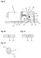
- a brake 17 is additionally arranged for mechanical closing sequence control on the moving leaf side door drive 3, which cooperates via a transmission element 18 with a arranged in the transmission 8 of the door leaf-side door drive 4 release element 19, whereby the active leaf 1 is detected in the closing direction in the open wing 2.
- the brake 17 is arranged on the gear side remote from the motor housing of the drive motor 6 of the door drive 3 in a brake housing 20 which is fixed to the motor housing.
- the rotary encoder 33 is in this case accommodated in a cover closing the brake housing 20, and interacts with a magnet 34 arranged on the motor shaft 7 for controlling the door drive 3.
- the guided out of the motor housing motor shaft 7 is guided through a recess in the brake housing 20.
- a freewheel 21 is fixed within the brake housing 20, on which a brake drum 22 is arranged rotationally fixed.
- the freewheel 21 causes a further opening of the active leaf 1 is possible with the inactive leaf 2 and thus a detected brake 17.
- the brake drum may be cup-shaped in order to reduce the mass and to reduce imbalances.
- the brake pad 23 may be biased by a spring element 27, 27 'in the direction of the brake drum 22.
- the spring element 27, 27 ' may be, for example, a steel wire spring 27, which is received in a groove of the brake pad 23.
- the brake pad 23 may also have extensions 26, which act on the brake pad 23 by springs 27 ', which are supported on the brake housing 20 to screws 35 in the braking direction.
- the rotatably mounted in the brake housing 20 expansion element 24 is substantially cylindrical and has in the region which is disposed between the brake pad 23, a contour 28, which is formed for example by two mutually parallel surfaces, and in the interrupted region of the brake pad 23rd engages, as it is in the Fig. 10 is shown.
- the distance of this area and the distance of the parallel surfaces of the contour 28 are coordinated so that in the position according to Fig. 10 the prestressed brake pad 23 acts brakingly on the brake drum 22.
- the brake pad 23 is pressed apart by the contour 28, whereby the brake 17 is released and the brake drum 22 is free.
- the motor shaft 7 and the gear 8 connected thereto can thus rotate freely with its output shaft 10.
- the tensioned when opening the active leaf 1 spring of the spring assembly 9 can cause a rotational movement of the output shaft 10 in the closing direction of the active leaf 1.
- the expansion element 24 may be formed so that it can be rotatably fixed in a recess in the brake housing 20 by snapping.
- the expansion element 24 may be provided with slots 36 which allow an elastic deformation during insertion of the expansion element 24 in the recess.
- a lever 25 is arranged on the latter, which is in operative connection via the transmission element 18 with the door leaf-side door drive 4.
- the transmission element 18 can in the simplest case be a cable. Instead of the lever 25, the cable can wrap around the spreader 24 and cause by a winding or winding the rotational movement.
- a cam 37 as in the Fig. 12 be shown, arranged or formed, whereby the balance of power can be influenced.
- the actuation of the transmission element 18 can be converted into an initial large rotational movement of the spreader 24 with a smaller force, with increasing counterforce by the force acting on the brake pad 23 steel wire spring 27 or the springs 27 'an increased force with less rotational movement.
- contour 28 is a curve in order to influence the course of the force as a function of the rotational movement of the expansion element 24, as shown in FIG Fig. 11 is shown.
- the provision of the expansion element 24 is effected by acting on the brake lining 23 in the braking position spring forces of the steel wire spring 27 or the springs 27 '.
- the triggering element 19 for regulating the closing sequence is arranged in the gear 8 of the door leaf-side door drive 4.
- the winding disk 15 rotatably connected to the output shaft 10 ' has a driver 29 which can be moved in a guide 32 arranged at least approximately semi-circularly in the triggering element 19.
- the trigger element 19 has opposite pivot lever 30, 30 ', to which the transmission element 18 optionally - depending on the mounting type of the door drive 3, 4 on the hinge side or hinge side - can be set, thereby changing without change to the door drives 3, 4, the logical operation the brake 17 takes place.
- an intermediate piece 31 is arranged, which leads out the attachment point of the transmission 8.
- the upper pivot lever 30 When mounting on the opposite side of the tape this is not required, as is accessible by a removable cover on the gear 8, the upper pivot lever 30.
- the inactive leaf 2 is in its closed position, the spring in the spring assembly 9 is relaxed.
- the rotatably mounted on the output shaft 10 winding disk 15 is located in the in Fig. 9 shown starting position.
- the driver 29 is in the semicircular Guide 32 in Appendix, whereby the trigger element 19 is pivoted counterclockwise. In this position, the transmission element 18 in the Fig. 9 shifted to the right, whereby a release of the brake 17 in the gangway side door drive 3 by turning the trigger element 19, as described above, is carried out.
- the output shaft 10 If the door drive 4 is energized to open the passive leaf 2, the output shaft 10 'rotates with the winding disk 15 and the driver 29 in the FIGS. 8 and 9 clockwise.
- the driver 29 comes out of the system with the end portion of the guide 32, whereby the on the output shaft 10 'freely rotatable trigger element 19 is pivoted by acting on the expansion element 24 restoring forces of the spring-loaded brake pad 23 in a clockwise direction.
- De brake lining 23 thus arrives in its position blocking the brake drum 22 for detecting the active leaf 1. Further opening of the active leaf 1 is possible at any time by the freewheel 21, but closing is prevented by the brake 17.
Landscapes
- Power-Operated Mechanisms For Wings (AREA)
Claims (17)
- Dispositif destiné à la commande de séquence de fermeture de portes pivotantes à deux battants, avec un battant actif (1) passant au-dessus, et un battant passif (2) passant en dessous, et avec des entraînements de porte (3, 4) du côté du battant actif et du côté du battant passif, pour l'ouverture motorisée des battants de porte (1, 2),
dans lequel chaque entraînement de porte (3, 4) présente une transmission avec un arbre de sortie (10, 10') sur lequel un bras glissant (13, 13') ou une tringlerie pour faire pivoter les battants de porte (1, 2) est disposé de façon solidaire en rotation,
et dans lequel l'arbre de sortie (10, 10') coopère avec un agencement de ressort (9) de l'entraînement de porte (3, 4) pour fermer les battants de porte (1, 2),
avec un système de blocage (17) pour le battant actif (1), qui peut être commandé en fonction de la position du battant passif (2), dans lequel le système de blocage (17) est centré par rapport à l'arbre de moteur (7) de l'entraînement de porte du côté du battant actif (3),
avec un élément de déclenchement (19) disposé dans la transmission (8) de l'entraînement de porte du côté du battant passif (4) et avec un élément de transmission (18), qui coopère par une extrémité avec le système de blocage (17) et par son autre extrémité avec l'élément de déclenchement (19) actionné par l'entraînement de porte du côté du battant passif (4) en fonction de la position du battant passif (2),
caractérisé en ce que
des leviers pivotants (30, 30') sont réalisés sur l'élément de déclenchement (19) en regard l'un de l'autre pour l'agencement sélectif de l'élément de transmission (18), de sorte que la direction d'actionnement du système de blocage (17) reste la même indépendamment d'un montage des entraînements de porte (3, 4) sur le côté de la penture ou sur le côté opposé à la penture. - Dispositif destiné à la commande de séquence de fermeture selon la revendication 1,
caractérisé en ce que l'élément de déclenchement (19) est monté de façon rotative sur l'arbre de sortie du côté du battant passif (10'). - Dispositif destiné à la commande de séquence de fermeture selon la revendication 1,
caractérisé en ce que l'élément de déclenchement (19) présente un guidage (32) pour l'engagement d'un entraîneur (29). - Dispositif destiné à la commande de séquence de fermeture selon la revendication 3,
caractérisé en ce que l'entraîneur (29) est monté sur un disque d'enroulement (15) assemblé de façon solidaire en rotation à l'arbre de sortie (10, 10'), qui est en liaison active avec l'agencement de ressort (9), dans lequel la position du disque d'enroulement (15) ou de l'entraîneur (29) correspond à la position d'ouverture du battant passif (2). - Dispositif destiné à la commande de séquence de fermeture selon la revendication 3,
caractérisé en ce que l'entraîneur (29) arrive en butée sur l'élément de déclenchement (19) dans la région terminale du guidage (32) pour une position d'ouverture du battant passif (2) à proximité de la position de fermeture, ce qui fait basculer l'élément de déclenchement (19). - Dispositif destiné à la commande de séquence de fermeture selon la revendication 1,
caractérisé en ce que le système de blocage est réalisé sous forme de frein à tambour. - Dispositif destiné à la commande de séquence de fermeture selon la revendication 6,
caractérisé en ce qu'une garniture de frein (23) est disposée à l'extérieur sur la surface d'enveloppe d'un tambour de frein (22). - Dispositif destiné à la commande de séquence de fermeture selon la revendication 7,
caractérisé en ce que le tambour de frein (22) reste libre dans une région de la garniture de frein (23) dans laquelle vient en prise un élément d'écartement (24). - Dispositif destiné à la commande de séquence de fermeture selon la revendication 8,
caractérisé en ce que l'élément d'écartement (24) présente un contour (28) qui, lors de la rotation de l'élément d'écartement (24), soulève la garniture de frein (23) du tambour de frein (22). - Dispositif destiné à la commande de séquence de fermeture selon la revendication 7,
caractérisé en ce que la garniture de frein (23) présente une précontrainte dans la direction du tambour de frein (22). - Dispositif destiné à la commande de séquence de fermeture selon la revendication 7,
caractérisé en ce que la garniture de frein (23) est précontrainte par un ressort (27, 27') dans la direction du tambour de frein (22). - Dispositif destiné à la commande de séquence de fermeture selon la revendication 11,
caractérisé en ce que le ressort (27) est disposé dans la garniture de frein (23) dans une rainure périphérique. - Dispositif destiné à la commande de séquence de fermeture selon la revendication 11,
caractérisé en ce que la garniture de frein (23) présente au moins une saillie (26), le ressort (27') étant disposé sur la saillie (26), de sorte que la garniture de frein (23) est sollicitée dans la direction du tambour de frein (22). - Dispositif destiné à la commande de séquence de fermeture selon les revendications 9 et 11,
caractérisé en ce que le contour (28) de l'élément d'écartement (24) est réalisé sous forme de courbe, de sorte que l'allure des forces lors du décollement de la garniture de frein (23) puisse être adaptée à une force opposée croissante du ressort (27, 27'). - Dispositif destiné à la commande de séquence de fermeture selon la revendication 8,
caractérisé en ce qu'un levier (25) d'actionnement est disposé sur l'élément d'écartement (24). - Dispositif destiné à la commande de séquence de fermeture selon les revendications 8 et 11,
caractérisé en ce qu'une came (37) d'actionnement est disposée sur l'élément d'écartement (24), de sorte que l'allure des forces lors du décollement de la garniture de frein (23) puisse être adaptée à une force opposée croissante du ressort (27, 27' ) . - Dispositif destiné à la commande de séquence de fermeture selon la revendication 7,
caractérisé en ce que le tambour de frein (22) est réalisé sous forme de coupe pour réduire la masse déplacée.
Applications Claiming Priority (1)
| Application Number | Priority Date | Filing Date | Title |
|---|---|---|---|
| DE102006028875A DE102006028875B3 (de) | 2006-06-21 | 2006-06-21 | Vorrichtung zur Schließfolgeregelung für zweiflügelige Drehtüren |
Publications (3)
| Publication Number | Publication Date |
|---|---|
| EP1870552A2 EP1870552A2 (fr) | 2007-12-26 |
| EP1870552A3 EP1870552A3 (fr) | 2010-07-28 |
| EP1870552B1 true EP1870552B1 (fr) | 2014-01-01 |
Family
ID=38320141
Family Applications (1)
| Application Number | Title | Priority Date | Filing Date |
|---|---|---|---|
| EP07110679.3A Active EP1870552B1 (fr) | 2006-06-21 | 2007-06-20 | Dispositif destiné à la commande de séquence de fermeture de portes pivotantes à deux battants |
Country Status (4)
| Country | Link |
|---|---|
| EP (1) | EP1870552B1 (fr) |
| DE (1) | DE102006028875B3 (fr) |
| DK (1) | DK1870552T3 (fr) |
| ES (1) | ES2445626T3 (fr) |
Cited By (1)
| Publication number | Priority date | Publication date | Assignee | Title |
|---|---|---|---|---|
| DE102022134910A1 (de) * | 2022-12-28 | 2024-07-04 | Dormakaba Deutschland Gmbh | Schließfolgeregler-Modul |
Families Citing this family (11)
| Publication number | Priority date | Publication date | Assignee | Title |
|---|---|---|---|---|
| DE102011000754A1 (de) * | 2011-02-16 | 2012-08-16 | Dorma Gmbh + Co. Kg | Türschließer für eine einen Standflügel und einen Gangflügel aufweisende zweiflügelige Tür mit einer Schließfolgeregelung |
| DE102013212649B9 (de) * | 2013-06-28 | 2014-08-28 | Geze Gmbh | Vorrichtung zur Regelung der Schließfolge einer zweiflügeligen Drehtüranlage |
| DE102013212648B3 (de) * | 2013-06-28 | 2014-06-12 | Geze Gmbh | Vorrichtung zur Regelung der Schließfolge einer zweiflügeligen Drehtüranlage |
| DE102013212650C5 (de) | 2013-06-28 | 2018-03-08 | Geze Gmbh | Vorrichtung zur Regelung der Schließfolge einer zweiflügeligen Drehtüranlage |
| DE102013212651B3 (de) | 2013-06-28 | 2014-04-03 | Geze Gmbh | Vorrichtung zur Regelung der Schließfolge einer zweiflügeligen Drehtüranlage |
| US10294707B2 (en) | 2014-03-31 | 2019-05-21 | Assa Abloy Entrance Systems Ab | Double door with inner brake |
| US10309142B2 (en) | 2014-03-31 | 2019-06-04 | Assa Abloy Entrance Systems Ab | Double door with coordinator brake |
| DE102014212570B4 (de) | 2014-06-30 | 2018-04-19 | Geze Gmbh | Blockiereinrichtung für eine Schließfolgeregelungsvorrichtung einer zweiflügeligen Drehtüranlage |
| DE102017201951A1 (de) * | 2017-02-08 | 2018-08-09 | Geze Gmbh | Verfahren zur Inbetriebnahme eines Tür- oder Fensterschliessers |
| DE102017201942A1 (de) | 2017-02-08 | 2018-08-09 | Geze Gmbh | Feststell- und/oder Notöffnungsanlage |
| CN111335769A (zh) * | 2020-03-10 | 2020-06-26 | 长虹美菱股份有限公司 | 一种自动开关门装置及应用其的冰箱 |
Citations (1)
| Publication number | Priority date | Publication date | Assignee | Title |
|---|---|---|---|---|
| DE3941711A1 (de) * | 1988-12-22 | 1990-06-28 | Geze Gmbh & Co | Vorrichtung zur regelung der schliessfolge von zweifluegeligen tueren |
Family Cites Families (6)
| Publication number | Priority date | Publication date | Assignee | Title |
|---|---|---|---|---|
| DE3421042A1 (de) * | 1984-06-06 | 1985-12-12 | Geze Gmbh, 7250 Leonberg | Bodentuerschliesser mit hydraulischer schliessfolgeregelung |
| DE4016283C1 (fr) * | 1990-05-21 | 1991-09-19 | Dorma Gmbh & Co Kg, 5828 Ennepetal, De | |
| DE4308560A1 (de) * | 1993-03-18 | 1994-09-22 | Dorma Gmbh & Co Kg | Schließfolgeregelung für eine über Türschließer selbstschließende, einen Standflügel und einen Gangflügel umfassende Tür |
| DE19532262B4 (de) * | 1995-09-01 | 2006-10-26 | Geze Gmbh | Vorrichtung zur Schließfolgeregelung für zweiflügelige Türen |
| DE29614151U1 (de) | 1996-08-16 | 1996-10-02 | Dorma Gmbh + Co. Kg, 58256 Ennepetal | Schließfolgeregelvorrichtung |
| DE10107461C2 (de) * | 2001-02-14 | 2003-07-17 | Dorma Gmbh & Co Kg | Schließfolgeregler |
-
2006
- 2006-06-21 DE DE102006028875A patent/DE102006028875B3/de active Active
-
2007
- 2007-06-20 DK DK07110679.3T patent/DK1870552T3/da active
- 2007-06-20 ES ES07110679.3T patent/ES2445626T3/es active Active
- 2007-06-20 EP EP07110679.3A patent/EP1870552B1/fr active Active
Patent Citations (1)
| Publication number | Priority date | Publication date | Assignee | Title |
|---|---|---|---|---|
| DE3941711A1 (de) * | 1988-12-22 | 1990-06-28 | Geze Gmbh & Co | Vorrichtung zur regelung der schliessfolge von zweifluegeligen tueren |
Cited By (2)
| Publication number | Priority date | Publication date | Assignee | Title |
|---|---|---|---|---|
| DE102022134910A1 (de) * | 2022-12-28 | 2024-07-04 | Dormakaba Deutschland Gmbh | Schließfolgeregler-Modul |
| DE102022134910B4 (de) | 2022-12-28 | 2025-02-20 | Dormakaba Deutschland Gmbh | Schließfolgeregler-Modul |
Also Published As
| Publication number | Publication date |
|---|---|
| DK1870552T3 (da) | 2014-01-27 |
| ES2445626T3 (es) | 2014-03-04 |
| EP1870552A2 (fr) | 2007-12-26 |
| DE102006028875B3 (de) | 2007-08-30 |
| EP1870552A3 (fr) | 2010-07-28 |
Similar Documents
| Publication | Publication Date | Title |
|---|---|---|
| EP1870552B1 (fr) | Dispositif destiné à la commande de séquence de fermeture de portes pivotantes à deux battants | |
| DE4231984C2 (de) | Elektromechanischer Drehtürantrieb | |
| DE212011100093U1 (de) | Drehflügeltürantriebsvorrichtung | |
| DE102009050185A1 (de) | Torantriebsvorrichtung mit Absolutwegsensor | |
| WO2009112562A1 (fr) | Dispositif d’entraînement de porte, en particulier entraînement direct | |
| EP1870551B1 (fr) | Dispositif destiné à contrôler la séquence de fermeture de portes pivotantes à deux battants | |
| WO2011098528A1 (fr) | Système d'entraînement de porte battante | |
| DE10260108B3 (de) | Freilaufvorrichtung für den Antrieb eines Flügels einer Tür oder eines Fensters | |
| EP1870553B1 (fr) | Dispositif destiné à la fermeture conséquente de portes rotatives à deux battants | |
| EP1870550B1 (fr) | Dispositif de commande de la séquence de fermeture de portes rotatives à deux battants | |
| EP0324075B1 (fr) | Dispositif de commande de la séquence de fermeture de portes à deux battants | |
| EP1801336A1 (fr) | Dispositif coordinateur de fermeture | |
| EP2206867B1 (fr) | Actionneur de porte destiné à l'actionnement d'un vantail | |
| DE19532262B4 (de) | Vorrichtung zur Schließfolgeregelung für zweiflügelige Türen | |
| DE10147477B4 (de) | Schließfolgeregler | |
| DE10122817A1 (de) | Schließfolgesteuerung mit Drehstange | |
| DE2923421C2 (de) | Antriebsvorrichtung für einen Tür- bzw. Torflügel | |
| DE102023134468B3 (de) | Antrieb mit Freilauffunktion für eine barrierefreie Begehung im Notfall | |
| EP1801337B1 (fr) | Dispositif de commande de la séquence de fermeture de portes à deux battants | |
| DE19532263B4 (de) | Vorrichtung zur Schließfolgeregelung für zweiflügelige Türen | |
| DE102022209690B4 (de) | Türschließer mit Freilauffunktion | |
| DE10107460A1 (de) | Schließfolgeregler | |
| DE102006041922B4 (de) | Feststeller für ein schwenkbares Bauteil, insbesondere eine Fahrzeugtür | |
| DE3941455A1 (de) | Vorrichtung zur regelung der schliessfolge von zweifluegeligen tueren | |
| EP1370741A1 (fr) | Regulateur de cycle de fermeture |
Legal Events
| Date | Code | Title | Description |
|---|---|---|---|
| PUAI | Public reference made under article 153(3) epc to a published international application that has entered the european phase |
Free format text: ORIGINAL CODE: 0009012 |
|
| AK | Designated contracting states |
Kind code of ref document: A2 Designated state(s): AT BE BG CH CY CZ DE DK EE ES FI FR GB GR HU IE IS IT LI LT LU LV MC MT NL PL PT RO SE SI SK TR |
|
| AX | Request for extension of the european patent |
Extension state: AL BA HR MK YU |
|
| PUAL | Search report despatched |
Free format text: ORIGINAL CODE: 0009013 |
|
| AK | Designated contracting states |
Kind code of ref document: A3 Designated state(s): AT BE BG CH CY CZ DE DK EE ES FI FR GB GR HU IE IS IT LI LT LU LV MC MT NL PL PT RO SE SI SK TR |
|
| AX | Request for extension of the european patent |
Extension state: AL BA HR MK RS |
|
| 17P | Request for examination filed |
Effective date: 20110125 |
|
| AKX | Designation fees paid |
Designated state(s): AT BE BG CH CY CZ DK EE ES FI FR GB GR HU IE IS IT LI LT LU LV MC MT NL PL PT RO SE SI SK TR |
|
| REG | Reference to a national code |
Ref country code: DE Ref legal event code: R108 Effective date: 20110309 Ref country code: DE Ref legal event code: 8566 |
|
| 17Q | First examination report despatched |
Effective date: 20120119 |
|
| GRAP | Despatch of communication of intention to grant a patent |
Free format text: ORIGINAL CODE: EPIDOSNIGR1 |
|
| INTG | Intention to grant announced |
Effective date: 20130729 |
|
| GRAS | Grant fee paid |
Free format text: ORIGINAL CODE: EPIDOSNIGR3 |
|
| GRAA | (expected) grant |
Free format text: ORIGINAL CODE: 0009210 |
|
| AK | Designated contracting states |
Kind code of ref document: B1 Designated state(s): AT BE BG CH CY CZ DK EE ES FI FR GB GR HU IE IS IT LI LT LU LV MC MT NL PL PT RO SE SI SK TR |
|
| REG | Reference to a national code |
Ref country code: GB Ref legal event code: FG4D Free format text: NOT ENGLISH |
|
| REG | Reference to a national code |
Ref country code: CH Ref legal event code: EP |
|
| REG | Reference to a national code |
Ref country code: DK Ref legal event code: T3 Effective date: 20140120 |
|
| REG | Reference to a national code |
Ref country code: IE Ref legal event code: FG4D Free format text: LANGUAGE OF EP DOCUMENT: GERMAN Ref country code: NL Ref legal event code: T3 |
|
| REG | Reference to a national code |
Ref country code: SE Ref legal event code: TRGR |
|
| REG | Reference to a national code |
Ref country code: NL Ref legal event code: T3 |
|
| REG | Reference to a national code |
Ref country code: AT Ref legal event code: REF Ref document number: 647691 Country of ref document: AT Kind code of ref document: T Effective date: 20140215 |
|
| REG | Reference to a national code |
Ref country code: ES Ref legal event code: FG2A Ref document number: 2445626 Country of ref document: ES Kind code of ref document: T3 Effective date: 20140304 |
|
| REG | Reference to a national code |
Ref country code: LT Ref legal event code: MG4D |
|
| PG25 | Lapsed in a contracting state [announced via postgrant information from national office to epo] |
Ref country code: LT Free format text: LAPSE BECAUSE OF FAILURE TO SUBMIT A TRANSLATION OF THE DESCRIPTION OR TO PAY THE FEE WITHIN THE PRESCRIBED TIME-LIMIT Effective date: 20140101 Ref country code: IS Free format text: LAPSE BECAUSE OF FAILURE TO SUBMIT A TRANSLATION OF THE DESCRIPTION OR TO PAY THE FEE WITHIN THE PRESCRIBED TIME-LIMIT Effective date: 20140501 |
|
| PG25 | Lapsed in a contracting state [announced via postgrant information from national office to epo] |
Ref country code: CY Free format text: LAPSE BECAUSE OF FAILURE TO SUBMIT A TRANSLATION OF THE DESCRIPTION OR TO PAY THE FEE WITHIN THE PRESCRIBED TIME-LIMIT Effective date: 20140101 Ref country code: PT Free format text: LAPSE BECAUSE OF FAILURE TO SUBMIT A TRANSLATION OF THE DESCRIPTION OR TO PAY THE FEE WITHIN THE PRESCRIBED TIME-LIMIT Effective date: 20140502 |
|
| PG25 | Lapsed in a contracting state [announced via postgrant information from national office to epo] |
Ref country code: LV Free format text: LAPSE BECAUSE OF FAILURE TO SUBMIT A TRANSLATION OF THE DESCRIPTION OR TO PAY THE FEE WITHIN THE PRESCRIBED TIME-LIMIT Effective date: 20140101 |
|
| PLBI | Opposition filed |
Free format text: ORIGINAL CODE: 0009260 |
|
| PG25 | Lapsed in a contracting state [announced via postgrant information from national office to epo] |
Ref country code: EE Free format text: LAPSE BECAUSE OF FAILURE TO SUBMIT A TRANSLATION OF THE DESCRIPTION OR TO PAY THE FEE WITHIN THE PRESCRIBED TIME-LIMIT Effective date: 20140101 Ref country code: RO Free format text: LAPSE BECAUSE OF FAILURE TO SUBMIT A TRANSLATION OF THE DESCRIPTION OR TO PAY THE FEE WITHIN THE PRESCRIBED TIME-LIMIT Effective date: 20140101 Ref country code: CZ Free format text: LAPSE BECAUSE OF FAILURE TO SUBMIT A TRANSLATION OF THE DESCRIPTION OR TO PAY THE FEE WITHIN THE PRESCRIBED TIME-LIMIT Effective date: 20140101 |
|
| 26 | Opposition filed |
Opponent name: ASSA ABLOY ENTRANCE SYSTEMS AB Effective date: 20141001 |
|
| PLAX | Notice of opposition and request to file observation + time limit sent |
Free format text: ORIGINAL CODE: EPIDOSNOBS2 |
|
| PG25 | Lapsed in a contracting state [announced via postgrant information from national office to epo] |
Ref country code: PL Free format text: LAPSE BECAUSE OF FAILURE TO SUBMIT A TRANSLATION OF THE DESCRIPTION OR TO PAY THE FEE WITHIN THE PRESCRIBED TIME-LIMIT Effective date: 20140101 Ref country code: SK Free format text: LAPSE BECAUSE OF FAILURE TO SUBMIT A TRANSLATION OF THE DESCRIPTION OR TO PAY THE FEE WITHIN THE PRESCRIBED TIME-LIMIT Effective date: 20140101 |
|
| PG25 | Lapsed in a contracting state [announced via postgrant information from national office to epo] |
Ref country code: MC Free format text: LAPSE BECAUSE OF FAILURE TO SUBMIT A TRANSLATION OF THE DESCRIPTION OR TO PAY THE FEE WITHIN THE PRESCRIBED TIME-LIMIT Effective date: 20140101 |
|
| PLAF | Information modified related to communication of a notice of opposition and request to file observations + time limit |
Free format text: ORIGINAL CODE: EPIDOSCOBS2 |
|
| PLBB | Reply of patent proprietor to notice(s) of opposition received |
Free format text: ORIGINAL CODE: EPIDOSNOBS3 |
|
| PG25 | Lapsed in a contracting state [announced via postgrant information from national office to epo] |
Ref country code: SI Free format text: LAPSE BECAUSE OF FAILURE TO SUBMIT A TRANSLATION OF THE DESCRIPTION OR TO PAY THE FEE WITHIN THE PRESCRIBED TIME-LIMIT Effective date: 20140101 |
|
| PG25 | Lapsed in a contracting state [announced via postgrant information from national office to epo] |
Ref country code: MT Free format text: LAPSE BECAUSE OF FAILURE TO SUBMIT A TRANSLATION OF THE DESCRIPTION OR TO PAY THE FEE WITHIN THE PRESCRIBED TIME-LIMIT Effective date: 20140101 |
|
| PG25 | Lapsed in a contracting state [announced via postgrant information from national office to epo] |
Ref country code: BG Free format text: LAPSE BECAUSE OF FAILURE TO SUBMIT A TRANSLATION OF THE DESCRIPTION OR TO PAY THE FEE WITHIN THE PRESCRIBED TIME-LIMIT Effective date: 20140101 |
|
| REG | Reference to a national code |
Ref country code: FR Ref legal event code: PLFP Year of fee payment: 10 |
|
| PLCK | Communication despatched that opposition was rejected |
Free format text: ORIGINAL CODE: EPIDOSNREJ1 |
|
| PG25 | Lapsed in a contracting state [announced via postgrant information from national office to epo] |
Ref country code: GR Free format text: LAPSE BECAUSE OF FAILURE TO SUBMIT A TRANSLATION OF THE DESCRIPTION OR TO PAY THE FEE WITHIN THE PRESCRIBED TIME-LIMIT Effective date: 20140402 |
|
| PG25 | Lapsed in a contracting state [announced via postgrant information from national office to epo] |
Ref country code: HU Free format text: LAPSE BECAUSE OF FAILURE TO SUBMIT A TRANSLATION OF THE DESCRIPTION OR TO PAY THE FEE WITHIN THE PRESCRIBED TIME-LIMIT; INVALID AB INITIO Effective date: 20070620 Ref country code: TR Free format text: LAPSE BECAUSE OF FAILURE TO SUBMIT A TRANSLATION OF THE DESCRIPTION OR TO PAY THE FEE WITHIN THE PRESCRIBED TIME-LIMIT Effective date: 20140101 |
|
| PLBN | Opposition rejected |
Free format text: ORIGINAL CODE: 0009273 |
|
| STAA | Information on the status of an ep patent application or granted ep patent |
Free format text: STATUS: OPPOSITION REJECTED |
|
| 27O | Opposition rejected |
Effective date: 20160709 |
|
| REG | Reference to a national code |
Ref country code: FR Ref legal event code: PLFP Year of fee payment: 11 |
|
| REG | Reference to a national code |
Ref country code: FR Ref legal event code: PLFP Year of fee payment: 12 |
|
| P01 | Opt-out of the competence of the unified patent court (upc) registered |
Effective date: 20230510 |
|
| PGFP | Annual fee paid to national office [announced via postgrant information from national office to epo] |
Ref country code: NL Payment date: 20230620 Year of fee payment: 17 Ref country code: IE Payment date: 20230620 Year of fee payment: 17 Ref country code: DK Payment date: 20230622 Year of fee payment: 17 |
|
| PGFP | Annual fee paid to national office [announced via postgrant information from national office to epo] |
Ref country code: LU Payment date: 20230621 Year of fee payment: 17 Ref country code: AT Payment date: 20230621 Year of fee payment: 17 |
|
| PGFP | Annual fee paid to national office [announced via postgrant information from national office to epo] |
Ref country code: BE Payment date: 20230620 Year of fee payment: 17 |
|
| PGFP | Annual fee paid to national office [announced via postgrant information from national office to epo] |
Ref country code: IT Payment date: 20230623 Year of fee payment: 17 Ref country code: ES Payment date: 20230828 Year of fee payment: 17 Ref country code: CH Payment date: 20230702 Year of fee payment: 17 |
|
| REG | Reference to a national code |
Ref country code: DK Ref legal event code: EBP Effective date: 20240630 |
|
| REG | Reference to a national code |
Ref country code: CH Ref legal event code: PL |
|
| REG | Reference to a national code |
Ref country code: NL Ref legal event code: MM Effective date: 20240701 |
|
| REG | Reference to a national code |
Ref country code: AT Ref legal event code: MM01 Ref document number: 647691 Country of ref document: AT Kind code of ref document: T Effective date: 20240620 |
|
| PG25 | Lapsed in a contracting state [announced via postgrant information from national office to epo] |
Ref country code: LU Free format text: LAPSE BECAUSE OF NON-PAYMENT OF DUE FEES Effective date: 20240620 |
|
| PG25 | Lapsed in a contracting state [announced via postgrant information from national office to epo] |
Ref country code: NL Free format text: LAPSE BECAUSE OF NON-PAYMENT OF DUE FEES Effective date: 20240701 |
|
| PG25 | Lapsed in a contracting state [announced via postgrant information from national office to epo] |
Ref country code: NL Free format text: LAPSE BECAUSE OF NON-PAYMENT OF DUE FEES Effective date: 20240701 |
|
| PG25 | Lapsed in a contracting state [announced via postgrant information from national office to epo] |
Ref country code: IE Free format text: LAPSE BECAUSE OF NON-PAYMENT OF DUE FEES Effective date: 20240620 |
|
| PG25 | Lapsed in a contracting state [announced via postgrant information from national office to epo] |
Ref country code: AT Free format text: LAPSE BECAUSE OF NON-PAYMENT OF DUE FEES Effective date: 20240620 Ref country code: BE Free format text: LAPSE BECAUSE OF NON-PAYMENT OF DUE FEES Effective date: 20240630 Ref country code: CH Free format text: LAPSE BECAUSE OF NON-PAYMENT OF DUE FEES Effective date: 20240630 |
|
| PG25 | Lapsed in a contracting state [announced via postgrant information from national office to epo] |
Ref country code: IT Free format text: LAPSE BECAUSE OF NON-PAYMENT OF DUE FEES Effective date: 20240620 |
|
| REG | Reference to a national code |
Ref country code: BE Ref legal event code: MM Effective date: 20240630 |
|
| PGFP | Annual fee paid to national office [announced via postgrant information from national office to epo] |
Ref country code: FI Payment date: 20250627 Year of fee payment: 19 |
|
| PG25 | Lapsed in a contracting state [announced via postgrant information from national office to epo] |
Ref country code: DK Free format text: LAPSE BECAUSE OF NON-PAYMENT OF DUE FEES Effective date: 20240630 |
|
| PGFP | Annual fee paid to national office [announced via postgrant information from national office to epo] |
Ref country code: GB Payment date: 20250618 Year of fee payment: 19 |
|
| PGFP | Annual fee paid to national office [announced via postgrant information from national office to epo] |
Ref country code: FR Payment date: 20250620 Year of fee payment: 19 |
|
| PGFP | Annual fee paid to national office [announced via postgrant information from national office to epo] |
Ref country code: SE Payment date: 20250618 Year of fee payment: 19 |
|
| REG | Reference to a national code |
Ref country code: ES Ref legal event code: FD2A Effective date: 20250730 |
|
| PG25 | Lapsed in a contracting state [announced via postgrant information from national office to epo] |
Ref country code: ES Free format text: LAPSE BECAUSE OF NON-PAYMENT OF DUE FEES Effective date: 20240621 |