EP1870552B1 - Device for regulating the closing sequence for swinging doors with two wings - Google Patents
Device for regulating the closing sequence for swinging doors with two wings Download PDFInfo
- Publication number
- EP1870552B1 EP1870552B1 EP07110679.3A EP07110679A EP1870552B1 EP 1870552 B1 EP1870552 B1 EP 1870552B1 EP 07110679 A EP07110679 A EP 07110679A EP 1870552 B1 EP1870552 B1 EP 1870552B1
- Authority
- EP
- European Patent Office
- Prior art keywords
- controlling
- closing sequence
- sequence according
- leaf
- door
- Prior art date
- Legal status (The legal status is an assumption and is not a legal conclusion. Google has not performed a legal analysis and makes no representation as to the accuracy of the status listed.)
- Active
Links
Images

Classifications
-
- E—FIXED CONSTRUCTIONS
- E05—LOCKS; KEYS; WINDOW OR DOOR FITTINGS; SAFES
- E05F—DEVICES FOR MOVING WINGS INTO OPEN OR CLOSED POSITION; CHECKS FOR WINGS; WING FITTINGS NOT OTHERWISE PROVIDED FOR, CONCERNED WITH THE FUNCTIONING OF THE WING
- E05F5/00—Braking devices, e.g. checks; Stops; Buffers
- E05F5/12—Braking devices, e.g. checks; Stops; Buffers specially for preventing the closing of a wing before another wing has been closed
-
- E—FIXED CONSTRUCTIONS
- E05—LOCKS; KEYS; WINDOW OR DOOR FITTINGS; SAFES
- E05F—DEVICES FOR MOVING WINGS INTO OPEN OR CLOSED POSITION; CHECKS FOR WINGS; WING FITTINGS NOT OTHERWISE PROVIDED FOR, CONCERNED WITH THE FUNCTIONING OF THE WING
- E05F15/00—Power-operated mechanisms for wings
- E05F15/60—Power-operated mechanisms for wings using electrical actuators
- E05F15/603—Power-operated mechanisms for wings using electrical actuators using rotary electromotors
- E05F15/611—Power-operated mechanisms for wings using electrical actuators using rotary electromotors for swinging wings
- E05F15/63—Power-operated mechanisms for wings using electrical actuators using rotary electromotors for swinging wings operated by swinging arms
-
- E—FIXED CONSTRUCTIONS
- E05—LOCKS; KEYS; WINDOW OR DOOR FITTINGS; SAFES
- E05F—DEVICES FOR MOVING WINGS INTO OPEN OR CLOSED POSITION; CHECKS FOR WINGS; WING FITTINGS NOT OTHERWISE PROVIDED FOR, CONCERNED WITH THE FUNCTIONING OF THE WING
- E05F3/00—Closers or openers with braking devices, e.g. checks; Construction of pneumatic or liquid braking devices
- E05F3/22—Additional arrangements for closers, e.g. for holding the wing in opened or other position
- E05F3/227—Additional arrangements for closers, e.g. for holding the wing in opened or other position mounted at the top of wings, e.g. details related to closer housings, covers, end caps or rails therefor
-
- E—FIXED CONSTRUCTIONS
- E05—LOCKS; KEYS; WINDOW OR DOOR FITTINGS; SAFES
- E05Y—INDEXING SCHEME ASSOCIATED WITH SUBCLASSES E05D AND E05F, RELATING TO CONSTRUCTION ELEMENTS, ELECTRIC CONTROL, POWER SUPPLY, POWER SIGNAL OR TRANSMISSION, USER INTERFACES, MOUNTING OR COUPLING, DETAILS, ACCESSORIES, AUXILIARY OPERATIONS NOT OTHERWISE PROVIDED FOR, APPLICATION THEREOF
- E05Y2201/00—Constructional elements; Accessories therefor
- E05Y2201/40—Motors; Magnets; Springs; Weights; Accessories therefor
- E05Y2201/404—Function thereof
- E05Y2201/41—Function thereof for closing
-
- E—FIXED CONSTRUCTIONS
- E05—LOCKS; KEYS; WINDOW OR DOOR FITTINGS; SAFES
- E05Y—INDEXING SCHEME ASSOCIATED WITH SUBCLASSES E05D AND E05F, RELATING TO CONSTRUCTION ELEMENTS, ELECTRIC CONTROL, POWER SUPPLY, POWER SIGNAL OR TRANSMISSION, USER INTERFACES, MOUNTING OR COUPLING, DETAILS, ACCESSORIES, AUXILIARY OPERATIONS NOT OTHERWISE PROVIDED FOR, APPLICATION THEREOF
- E05Y2201/00—Constructional elements; Accessories therefor
- E05Y2201/40—Motors; Magnets; Springs; Weights; Accessories therefor
- E05Y2201/404—Function thereof
- E05Y2201/422—Function thereof for opening
-
- E—FIXED CONSTRUCTIONS
- E05—LOCKS; KEYS; WINDOW OR DOOR FITTINGS; SAFES
- E05Y—INDEXING SCHEME ASSOCIATED WITH SUBCLASSES E05D AND E05F, RELATING TO CONSTRUCTION ELEMENTS, ELECTRIC CONTROL, POWER SUPPLY, POWER SIGNAL OR TRANSMISSION, USER INTERFACES, MOUNTING OR COUPLING, DETAILS, ACCESSORIES, AUXILIARY OPERATIONS NOT OTHERWISE PROVIDED FOR, APPLICATION THEREOF
- E05Y2201/00—Constructional elements; Accessories therefor
- E05Y2201/40—Motors; Magnets; Springs; Weights; Accessories therefor
- E05Y2201/43—Motors
- E05Y2201/434—Electromotors; Details thereof
-
- E—FIXED CONSTRUCTIONS
- E05—LOCKS; KEYS; WINDOW OR DOOR FITTINGS; SAFES
- E05Y—INDEXING SCHEME ASSOCIATED WITH SUBCLASSES E05D AND E05F, RELATING TO CONSTRUCTION ELEMENTS, ELECTRIC CONTROL, POWER SUPPLY, POWER SIGNAL OR TRANSMISSION, USER INTERFACES, MOUNTING OR COUPLING, DETAILS, ACCESSORIES, AUXILIARY OPERATIONS NOT OTHERWISE PROVIDED FOR, APPLICATION THEREOF
- E05Y2400/00—Electronic control; Electrical power; Power supply; Power or signal transmission; User interfaces
- E05Y2400/10—Electronic control
- E05Y2400/30—Electronic control of motors
- E05Y2400/3013—Electronic control of motors during manual wing operation
- E05Y2400/3015—Power assistance
-
- E—FIXED CONSTRUCTIONS
- E05—LOCKS; KEYS; WINDOW OR DOOR FITTINGS; SAFES
- E05Y—INDEXING SCHEME ASSOCIATED WITH SUBCLASSES E05D AND E05F, RELATING TO CONSTRUCTION ELEMENTS, ELECTRIC CONTROL, POWER SUPPLY, POWER SIGNAL OR TRANSMISSION, USER INTERFACES, MOUNTING OR COUPLING, DETAILS, ACCESSORIES, AUXILIARY OPERATIONS NOT OTHERWISE PROVIDED FOR, APPLICATION THEREOF
- E05Y2400/00—Electronic control; Electrical power; Power supply; Power or signal transmission; User interfaces
- E05Y2400/10—Electronic control
- E05Y2400/30—Electronic control of motors
- E05Y2400/302—Electronic control of motors during electric motor braking
-
- E—FIXED CONSTRUCTIONS
- E05—LOCKS; KEYS; WINDOW OR DOOR FITTINGS; SAFES
- E05Y—INDEXING SCHEME ASSOCIATED WITH SUBCLASSES E05D AND E05F, RELATING TO CONSTRUCTION ELEMENTS, ELECTRIC CONTROL, POWER SUPPLY, POWER SIGNAL OR TRANSMISSION, USER INTERFACES, MOUNTING OR COUPLING, DETAILS, ACCESSORIES, AUXILIARY OPERATIONS NOT OTHERWISE PROVIDED FOR, APPLICATION THEREOF
- E05Y2800/00—Details, accessories and auxiliary operations not otherwise provided for
- E05Y2800/15—Applicability
- E05Y2800/17—Universally applicable
- E05Y2800/172—Universally applicable on different wing or frame locations
-
- E—FIXED CONSTRUCTIONS
- E05—LOCKS; KEYS; WINDOW OR DOOR FITTINGS; SAFES
- E05Y—INDEXING SCHEME ASSOCIATED WITH SUBCLASSES E05D AND E05F, RELATING TO CONSTRUCTION ELEMENTS, ELECTRIC CONTROL, POWER SUPPLY, POWER SIGNAL OR TRANSMISSION, USER INTERFACES, MOUNTING OR COUPLING, DETAILS, ACCESSORIES, AUXILIARY OPERATIONS NOT OTHERWISE PROVIDED FOR, APPLICATION THEREOF
- E05Y2900/00—Application of doors, windows, wings or fittings thereof
- E05Y2900/10—Application of doors, windows, wings or fittings thereof for buildings or parts thereof
- E05Y2900/13—Type of wing
- E05Y2900/132—Doors
Definitions
- the invention relates to a device for closing sequence control for double-leaf hinged doors according to the preamble of claim 1.
- a device for closing sequence control for double-leaf doors with an underpowering inactive leaf and a swinging active leaf known, each cooperating with fixed mounted drives, each drive having an output shaft which cooperates with an electric motor for opening and a closer unit with closing spring for closing.
- the active leaf is operatively connected to a blocking device, which is controllable in dependence on the position of the passive leaf, by a transmission member is provided, which cooperates with its one end to the blocking device and with its other end with an actuated by the inactive leaf or a connected part actuator , which is arranged in the region of the housing of the passive leaf drive.
- the blocking device acts on the motor shaft of the moving leaf drive, which is in operative connection with the output shaft of the moving leaf drive.
- the active leaf is detectable by means of a releasable from the passive leaf locking mechanism.
- the axis of rotation of the inactive leaf is provided with a cam disc, which is in operative connection via an actuating element with a brake acting on the axis of rotation of the active leaf. It is provided in the brake area formed by an overload spring overload protection.
- the brake is designed as a two-part shoe brake, which surrounds a provided on the axis of the active leaf freewheel.
- the closing sequence control interacts with the rotary axes of the door leaves and can not be used in conjunction with automatic door drives.
- WO 98/07944 A1 discloses a closing sequence control device for a two-leaf, a passive leaf and a wing comprising comprehensive door whose door is each a drive unit for the controllable opening and / or closing in conjunction with a moving the door leaf serving power transmission shaft.
- the power transmission shaft is adaptively equipped with an exclusively mechanically operating device for controlling the closing sequence, namely a first-action leaf opening first on the basis of a detector signal and a subsequently likewise opening passive leaf.
- the power wing associated drive unit can be detected and released by an operable by the inactive leaf locking member, wherein a corresponding element is connected between the drive units.
- the door leaves are provided with an electro-hydraulic door drive, wherein a blocking valve is connected in the hydraulic system of the moving leaf drive and controlled by the passive leaf drive for blocking the active leaf.
- the invention has for its object to provide a universally arranged closing sequence control.
- Closing sequence controls are required for double-leaf revolving doors when the door leaves are provided with a door rebate, with the fixed leaf with its door rebate forms the stop for the active leaf. Since the two leaves overlap in the central region, the passive leaf must always be closed first before the active leaf closes completely, since otherwise the passive leaf abuts the overlap of the active leaf and the door remains partially open, which is inadmissible especially in the case of smoke and fire doors is. Therefore, the closing sequence control has a controlled by the fixed wing locking device, which detects the active leaf in an at least partially open position with open wing, and thus allows closing of the inactive leaf in front of the active leaf.
- the device according to the invention for closing sequence control ensures that on a double-leaf, having a moving leaf and a passive leaf door equipped with door drives the undercutting passive leaf logically closes in front of the sweeping active leaf.
- the active leaf is held by a blocking device in a partially open position when the inactive leaf is open, wherein the blocking device cooperates with an actuatable by the inactive leaf triggering device.
- the door drives are arranged above the door leaf and are operatively connected via rods or slide arms, which engage with sliders in a wing fixedly arranged slide, with the respective door.
- the door drives on the hinge side, ie on the side of the doors on which the door wings are pivotally received in door hinges or door hinges, or on the corresponding opposite side of the doors, the hinge opposite side.
- the door drives are designed for motorized opening and have for actuating in the closing direction on a spring arrangement.
- a controlled electric motor and the spring arrangement acts on a gear, which cooperates with the sliding arm or linkage for wing actuation.
- the door drive for the active leaf and for the fixed leaf are constructed essentially identically.
- the gangway-side door drive in addition to a brake as a blocking device, which is arranged on the motor shaft.
- the door leaf-side door drive additionally has a triggering element, which actuates the gangway-side brake via a transmission element arranged between the door drives.
- the motor shaft of the gangway side door drive is extended into a brake housing.
- a freewheel is rotatably mounted on which a brake drum is fixed.
- the freewheel allows opening of the active leaf when the brake is locked.
- the brake drum is surrounded by a brake pad which does not completely surround the brake drum.
- the brake pad has a directed towards the brake drum bias, which can also be reinforced by one or more springs, since such friction pads usually do not have high elasticity for a sufficiently large bias.
- the free area of the annular brake pad allows the engagement of a spreading element, which is designed in the manner of an eccentric. A rotation of the expansion element causes a release of the brake by the brake pad is lifted from the brake drum.
- the rotatably mounted in the brake housing expansion element is substantially cylindrical and has in the region which is arranged between the brake pad, a non-circular contour, whereby the brake pad is pressed apart depending on the angular position of the expansion element.
- the rotation of the expansion element is effected by the stand-wing-side trigger, which is connected by a transmission element, such as a cable or a belt, with the expansion element.
- a transmission element such as a cable or a belt
- a lever or a cam can be arranged to force transmission on the expansion element, which acts on the transmission element.
- the release element arranged in the gearbox of the door leaf-side door drive is rotatably mounted on the output shaft and cooperates with a winding disk which is arranged non-rotatably on the output shaft.
- a rope or band is wound up when opening the door leaf, which tensions a closing spring supported in the spring arrangement.
- the trigger element is released, and arranged on the transition wing brake brake expander rotates by the restoring force of the brake pad and possibly also acting on these springs so that the brake pad comes into contact with the brake drum and the Motor shaft in the closing direction notes.
- the trigger element is operatively connected by the transmission element, such as a cable, with the expansion element for actuating the brake.
- the transmission element can be optionally set to two opposing pivot levers on the trigger element, which is carried out without modification to the drives the logical operation of the brake.
- opening of the active leaf is possible even when the brake is detected by the arranged on the motor shaft freewheel. Damage to the door system through improper manual operation of the detected active leaf is avoided by the brake is designed so that in case of overload, the brake pad can slip on the brake drum.
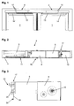
- the Fig. 1 shows a two-leaf door with a moving leaf 1 and a passive leaf 2.
- a door drive 3, 4 is arranged, which has a rotatably connected to an output shaft 10, 10 'sliding arm 13, 13' for transmitting power.
- a slider is arranged rotatably on the end facing away from the door drive 3, 4, which is guided in a guide rail 14, 14' fixed to the wing.
- a linkage of two pivotally interconnected lever arms on the output shaft 10, 10' may be arranged, wherein the linkage at the other end on the respective door 1, 2 is rotatably fixed.
- the door drives 3, 4 can be arranged on the hinge side, the side on which the door hinges are arranged, or on the opposite side, the so-called hinge opposite side.
- the door drive 3, 4 is mounted rotated by 180 ° depending on the mounting on the belt or hinge side.
- the output shaft 10, 10 ' is accessible on both sides of the transmission 8 for mounting the sliding arm 13 or the linkage.
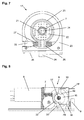
- FIG. 2 the components of the substantially identical door drives 3, 4 are shown in a schematic diagram on the basis of the door leaf-side door drive 3.
- a drive motor 6 is connected to a not shown in the figure motor shaft 7 with a gear 8.
- the gear 8 cooperates with a spring arrangement 9, which serves as an energy store and a closing of the door 1 or 2 causes.
- a closing spring is arranged in a receiving space, wherein the closing spring is tensioned when opening the door leaf 1 or 2.
- the output shaft 10 is arranged.
- a control unit 11 for controlling the door drive 3 or 4 is provided.
- Fig. 4 is a plan view of the low-wing door drive 4 shown, wherein the transmission is open.
- a worm is rotatably mounted, which forms a gear reducer 8 with an arrangement of gears.
- a transmission shaft is guided to the outside and forms the output shaft 10 ', at the shaft end of the sliding arm 13' is fixed.
- a winding disk 15 is rotatably disposed in the transmission 8 on the output shaft 10, on which a flat belt 16, a band or another flexible element arranged in a loop and fixed end.
- the flat belt 16 cooperates with a arranged in the spring assembly 9 spring to the tension and relaxation together.
- the motor shaft 7 is also led out on the gear side facing away from the motor housing to a rotary encoder 33 to the controller 11 of the drive motor 6 of the respective door drive 3 and 4 to arrange, as in Fig. 3 is shown.
- a learning run is carried out during which the closed and open positions of the door leaves 1, 2 are detected.
- the controller 11 detects the position of the door leaf 1, 2 and thus can detect possible obstacles in the pivoting range of the door leaf 1, 2 during operation. This would also be an electrical control of the closing sequence of the door 1, 2 in principle conceivable, however, a closing sequence control on smoke and fire doors must continue to function reliably even in case of power failure and this function will then be additionally hedged.
- FIGS. 8 and 9 If the drive motor 6 is energized to open the door leaf 1, 2, causes this via the transmission 8, a rotation of the output shaft 10, 10 '. About the force-transmitting slide arm 13, 13 ', the rotational movement of the Output shaft 10, 10 'so implemented in an opening movement of the door leaf 1, 2. The rotational movement of the output shaft 10 causes by the rotationally fixed arrangement and a same direction of rotation of the winding disk 15, whereby the flat belt 16 is wound and pulled out of the spring assembly 9, whereby the closing spring is tensioned.
- the relaxing closing spring effects a turning back of the winding disk 15 and thus of the output shaft 10, 10 '.
- the guided in the slide rail 14, 14 'sliding arm 13, 13' sets this rotational movement of the output shaft 10, 10 'in a closing movement of the door 1, 2 to.
- the drive motor 6 can in this case be operated by the controller 11 as a generator to decelerate the closing operation.
- a brake 17 is additionally arranged for mechanical closing sequence control on the moving leaf side door drive 3, which cooperates via a transmission element 18 with a arranged in the transmission 8 of the door leaf-side door drive 4 release element 19, whereby the active leaf 1 is detected in the closing direction in the open wing 2.
- the brake 17 is arranged on the gear side remote from the motor housing of the drive motor 6 of the door drive 3 in a brake housing 20 which is fixed to the motor housing.
- the rotary encoder 33 is in this case accommodated in a cover closing the brake housing 20, and interacts with a magnet 34 arranged on the motor shaft 7 for controlling the door drive 3.
- the guided out of the motor housing motor shaft 7 is guided through a recess in the brake housing 20.
- a freewheel 21 is fixed within the brake housing 20, on which a brake drum 22 is arranged rotationally fixed.
- the freewheel 21 causes a further opening of the active leaf 1 is possible with the inactive leaf 2 and thus a detected brake 17.
- the brake drum may be cup-shaped in order to reduce the mass and to reduce imbalances.
- the brake pad 23 may be biased by a spring element 27, 27 'in the direction of the brake drum 22.
- the spring element 27, 27 ' may be, for example, a steel wire spring 27, which is received in a groove of the brake pad 23.
- the brake pad 23 may also have extensions 26, which act on the brake pad 23 by springs 27 ', which are supported on the brake housing 20 to screws 35 in the braking direction.
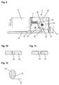
- the rotatably mounted in the brake housing 20 expansion element 24 is substantially cylindrical and has in the region which is disposed between the brake pad 23, a contour 28, which is formed for example by two mutually parallel surfaces, and in the interrupted region of the brake pad 23rd engages, as it is in the Fig. 10 is shown.
- the distance of this area and the distance of the parallel surfaces of the contour 28 are coordinated so that in the position according to Fig. 10 the prestressed brake pad 23 acts brakingly on the brake drum 22.
- the brake pad 23 is pressed apart by the contour 28, whereby the brake 17 is released and the brake drum 22 is free.
- the motor shaft 7 and the gear 8 connected thereto can thus rotate freely with its output shaft 10.
- the tensioned when opening the active leaf 1 spring of the spring assembly 9 can cause a rotational movement of the output shaft 10 in the closing direction of the active leaf 1.
- the expansion element 24 may be formed so that it can be rotatably fixed in a recess in the brake housing 20 by snapping.
- the expansion element 24 may be provided with slots 36 which allow an elastic deformation during insertion of the expansion element 24 in the recess.
- a lever 25 is arranged on the latter, which is in operative connection via the transmission element 18 with the door leaf-side door drive 4.
- the transmission element 18 can in the simplest case be a cable. Instead of the lever 25, the cable can wrap around the spreader 24 and cause by a winding or winding the rotational movement.
- a cam 37 as in the Fig. 12 be shown, arranged or formed, whereby the balance of power can be influenced.
- the actuation of the transmission element 18 can be converted into an initial large rotational movement of the spreader 24 with a smaller force, with increasing counterforce by the force acting on the brake pad 23 steel wire spring 27 or the springs 27 'an increased force with less rotational movement.
- contour 28 is a curve in order to influence the course of the force as a function of the rotational movement of the expansion element 24, as shown in FIG Fig. 11 is shown.
- the provision of the expansion element 24 is effected by acting on the brake lining 23 in the braking position spring forces of the steel wire spring 27 or the springs 27 '.
- the triggering element 19 for regulating the closing sequence is arranged in the gear 8 of the door leaf-side door drive 4.
- the winding disk 15 rotatably connected to the output shaft 10 ' has a driver 29 which can be moved in a guide 32 arranged at least approximately semi-circularly in the triggering element 19.
- the trigger element 19 has opposite pivot lever 30, 30 ', to which the transmission element 18 optionally - depending on the mounting type of the door drive 3, 4 on the hinge side or hinge side - can be set, thereby changing without change to the door drives 3, 4, the logical operation the brake 17 takes place.
- an intermediate piece 31 is arranged, which leads out the attachment point of the transmission 8.
- the upper pivot lever 30 When mounting on the opposite side of the tape this is not required, as is accessible by a removable cover on the gear 8, the upper pivot lever 30.
- the inactive leaf 2 is in its closed position, the spring in the spring assembly 9 is relaxed.
- the rotatably mounted on the output shaft 10 winding disk 15 is located in the in Fig. 9 shown starting position.
- the driver 29 is in the semicircular Guide 32 in Appendix, whereby the trigger element 19 is pivoted counterclockwise. In this position, the transmission element 18 in the Fig. 9 shifted to the right, whereby a release of the brake 17 in the gangway side door drive 3 by turning the trigger element 19, as described above, is carried out.
- the output shaft 10 If the door drive 4 is energized to open the passive leaf 2, the output shaft 10 'rotates with the winding disk 15 and the driver 29 in the FIGS. 8 and 9 clockwise.
- the driver 29 comes out of the system with the end portion of the guide 32, whereby the on the output shaft 10 'freely rotatable trigger element 19 is pivoted by acting on the expansion element 24 restoring forces of the spring-loaded brake pad 23 in a clockwise direction.
- De brake lining 23 thus arrives in its position blocking the brake drum 22 for detecting the active leaf 1. Further opening of the active leaf 1 is possible at any time by the freewheel 21, but closing is prevented by the brake 17.
Landscapes
- Power-Operated Mechanisms For Wings (AREA)
Description
Die Erfindung betrifft eine Vorrichtung zur Schließfolgeregelung für zweiflügelige Drehtüren nach dem Oberbegriff des Anspruchs 1.The invention relates to a device for closing sequence control for double-leaf hinged doors according to the preamble of
Aus der
Diese Anordnung ist aufwändig aufgebaut erlaubt nur eine Montageart, wobei die Antriebsmotoren einander zugewandt sind.This arrangement is elaborate allows only one type of mounting, the drive motors are facing each other.
Aus der
Die Schließfolgeregelung wirkt mit den Drehachsen der Türflügel zusammen und ist nicht in Verbindung mit automatischen Türantrieben verwendbar.The closing sequence control interacts with the rotary axes of the door leaves and can not be used in conjunction with automatic door drives.
Aus der
In der
Der Erfindung liegt die Aufgabe zugrunde, eine universell anordenbare Schließfolgeregelung zu schaffen.The invention has for its object to provide a universally arranged closing sequence control.
Die Aufgabe wird durch die Merkmale des Anspruchs 1 gelöst.The object is solved by the features of
Die Unteransprüche bilden vorteilhafte Ausgestaltungsmöglichkeiten der Erfindung.The subclaims form advantageous embodiments of the invention.
Schließfolgeregelungen sind für zweiflügelige Drehtüren dann erforderlich, wenn die Türflügel mit einem Türfalz versehen sind, wobei der Standflügel mit seinem Türfalz den Anschlag für den Gangflügel bildet. Da sich die beiden Türflügel im Mittelbereich überlappen, muss beim Schließvorgang stets zuerst der Standflügel geschlossen sein, ehe der Gangflügel vollständig schließt, da ansonsten der Standflügel an der Überlappung des Gangflügels anstößt und die Tür teilweise geöffnet bleibt, was insbesondere bei Rauch- und Brandschutztüren unzulässig ist. Die Schließfolgeregelung weist daher eine vom Standflügel gesteuerte Feststellvorrichtung auf, welche bei geöffnetem Standflügel den Gangflügel in einer zumindest teilweise geöffneten Position feststellt, und so ein Schließen des Standflügels vor dem Gangflügel ermöglicht.Closing sequence controls are required for double-leaf revolving doors when the door leaves are provided with a door rebate, with the fixed leaf with its door rebate forms the stop for the active leaf. Since the two leaves overlap in the central region, the passive leaf must always be closed first before the active leaf closes completely, since otherwise the passive leaf abuts the overlap of the active leaf and the door remains partially open, which is inadmissible especially in the case of smoke and fire doors is. Therefore, the closing sequence control has a controlled by the fixed wing locking device, which detects the active leaf in an at least partially open position with open wing, and thus allows closing of the inactive leaf in front of the active leaf.
Die erfindungsgemäße Vorrichtung zur Schließfolgeregelung stellt sicher, dass an einer zweiflügeligen, einen Gangflügel und einen Standflügel aufweisenden, mit Türantrieben ausgestatteten Tür der unterschlagende Standflügel folgerichtig vor dem überschlagenden Gangflügel schließt. Dazu wird der Gangflügel bei geöffnetem Standflügel durch eine Blockiervorrichtung in einer teilweise geöffneten Stellung gehalten, wobei die Blockiervorrichtung mit einer vom Standflügel betätigbaren Auslöseeinrichtung zusammenwirkt.The device according to the invention for closing sequence control ensures that on a double-leaf, having a moving leaf and a passive leaf door equipped with door drives the undercutting passive leaf logically closes in front of the sweeping active leaf. For this purpose, the active leaf is held by a blocking device in a partially open position when the inactive leaf is open, wherein the blocking device cooperates with an actuatable by the inactive leaf triggering device.
Die Türantriebe sind dabei oberhalb der Türflügel angeordnet und sind über Gestänge oder Gleitarme, die mit Gleitern in eine flügelfest angeordnete Gleitschiene eingreifen, mit dem jeweiligen Türflügel wirkverbunden.The door drives are arranged above the door leaf and are operatively connected via rods or slide arms, which engage with sliders in a wing fixedly arranged slide, with the respective door.
Es besteht die Möglichkeit, die Türantriebe auf der Bandseite, also auf der Seite der Türen, auf welcher die Türflügel schwenkbar in Türbändern oder Türscharnieren aufgenommen sind, zu montieren, oder auf der entsprechend gegenüberliegenden Seite der Türen, der Bandgegenseite.It is possible to mount the door drives on the hinge side, ie on the side of the doors on which the door wings are pivotally received in door hinges or door hinges, or on the corresponding opposite side of the doors, the hinge opposite side.
Die Türantriebe sind zum motorischen Öffnen ausgebildet und weisen zur Betätigung in Schließrichtung eine Federanordnung auf. Dabei wirkt ein gesteuerter Elektromotor und die Federanordnung auf ein Getriebe ein, das mit dem Gleitarm oder Gestänge zur Flügelbetätigung zusammenwirkt. Der Türantrieb für den Gangflügel und für den Standflügel sind dabei im Wesentlichen identisch aufgebaut. Zur Schließfolgeregelung weist der gangflügelseitige Türantrieb zusätzlich eine Bremse als Blockiervorrichtung auf, die auf der Motorwelle angeordnet ist. Der standflügelseitige Türantrieb weist zusätzlich ein Auslöseelement auf, das über ein, zwischen den Türantrieben angeordnetes Übertragungselement, die gangflügelseitige Bremse betätigt.The door drives are designed for motorized opening and have for actuating in the closing direction on a spring arrangement. In this case, a controlled electric motor and the spring arrangement acts on a gear, which cooperates with the sliding arm or linkage for wing actuation. The door drive for the active leaf and for the fixed leaf are constructed essentially identically. For closing sequence control, the gangway-side door drive in addition to a brake as a blocking device, which is arranged on the motor shaft. The door leaf-side door drive additionally has a triggering element, which actuates the gangway-side brake via a transmission element arranged between the door drives.
Die Motorwelle des gangflügelseitigen Türantriebs ist in ein Bremsgehäuse hinein verlängert. Auf dieser Verlängerung der Motorwelle ist ein Freilauf drehfest angeordnet, auf dem eine Bremstrommel festgelegt ist. Der Freilauf ermöglicht ein Öffnen des Gangflügels bei blockierter Bremse. Die Bremstrommel ist von einem Bremsbelag umgeben, welcher die Bremstrommel nicht vollständig umschließt. Der Bremsbelag weist eine in Richtung auf die Bremstrommel gerichtete Vorspannung auf, die auch durch eine oder mehrere Federn verstärkt werden kann, da derartige Reibbeläge üblicherweise keine hohe Elastizität für eine ausreichend große Vorspannung aufweisen.The motor shaft of the gangway side door drive is extended into a brake housing. On this extension of the motor shaft, a freewheel is rotatably mounted on which a brake drum is fixed. The freewheel allows opening of the active leaf when the brake is locked. The brake drum is surrounded by a brake pad which does not completely surround the brake drum. The brake pad has a directed towards the brake drum bias, which can also be reinforced by one or more springs, since such friction pads usually do not have high elasticity for a sufficiently large bias.
Der freie Bereich des ringförmigen Bremsbelags ermöglicht den Eingriff eines Spreizelements, das in der Art eines Exzenters ausgebildet ist. Ein Drehen des Spreizelements bewirkt ein Lösen der Bremse, indem der Bremsbelag von der Bremstrommel abgehoben wird.The free area of the annular brake pad allows the engagement of a spreading element, which is designed in the manner of an eccentric. A rotation of the expansion element causes a release of the brake by the brake pad is lifted from the brake drum.
Das drehbar im Bremsgehäuse gelagerte Spreizelement ist im Wesentlichen zylindrisch ausgebildet und weist in dem Bereich, der zwischen dem Bremsbelag angeordnet ist, eine unrunde Kontur auf, wodurch der Bremsbelag abhängig von der Winkelstellung des Spreizelements, auseinander gedrückt wird.The rotatably mounted in the brake housing expansion element is substantially cylindrical and has in the region which is arranged between the brake pad, a non-circular contour, whereby the brake pad is pressed apart depending on the angular position of the expansion element.
Die Drehung des Spreizelements wird durch den standflügelseitigen Auslöser bewirkt, der durch ein Übertragungselement, beispielsweise einen Seilzug oder ein Band, mit dem Spreizelement verbunden ist. Dazu kann zur Kraftübersetzung am Spreizelement ein Hebel oder eine Kurvenscheibe angeordnet sein, an der das Übertragungselement angreift.The rotation of the expansion element is effected by the stand-wing-side trigger, which is connected by a transmission element, such as a cable or a belt, with the expansion element. For this purpose, a lever or a cam can be arranged to force transmission on the expansion element, which acts on the transmission element.
Das im Getriebe des standflügelseitigen Türantriebs angeordnete Auslöseelement ist auf der Abtriebswelle drehbar angeordnet und wirkt mit einer Wickelscheibe zusammen, die drehfest auf der Abtriebswelle angeordnet ist. Auf die Wickelscheibe wird beim Öffnen des Türflügels ein Seil oder Band aufgewickelt, das eine in der Federanordnung abgestützte Schließfeder spannt. Durch einen auf der Wickelscheibe angeordneten Mitnehmer ist das Auslöseelement in der Geschlossenstellung des Türflügels so verschwenkt, dass die gangflügelseitige Bremse gelöst ist, und ein Schließen des Gangflügels durch die Schließfeder des gangflügelseitigen Türantriebs möglich ist. Wird der Standflügel durch den Türantrieb geöffnet, so wird das Auslöseelement frei, und das an der gangflügelseitigen Bremse angeordnete Spreizelement dreht sich durch die Rückstellkraft des Bremsbelags und der möglicherweise zusätzlich auf diesen einwirkenden Federn so, dass der Bremsbelag in Anlage mit der Bremstrommel gelangt und die Motorwelle in Schließrichtung feststellt. Das Auslöselement ist durch das Übertragungselement, beispielsweise einen Seilzug, mit dem Spreizelement zur Betätigung der Bremse wirkverbunden. Um das Betätigen der Bremse auch bei den unterschiedlichen Montagearten der Türantriebe einfach zu ermöglichen, kann das Übertragungselement wahlweise an zwei einander gegenüberliegenden Schwenkhebeln am Auslöseelement festgelegt werden, wodurch ohne Änderung an den Antrieben die folgerichtige Betätigung der Bremse erfolgt.The release element arranged in the gearbox of the door leaf-side door drive is rotatably mounted on the output shaft and cooperates with a winding disk which is arranged non-rotatably on the output shaft. On the winding disk a rope or band is wound up when opening the door leaf, which tensions a closing spring supported in the spring arrangement. By arranged on the winding disc driver, the trigger element is pivoted in the closed position of the door so that the gangway side brake is released, and closing of the active leaf by the closing spring of the gangway side door drive is possible. If the inactive leaf is opened by the door drive, then the trigger element is released, and arranged on the transition wing brake brake expander rotates by the restoring force of the brake pad and possibly also acting on these springs so that the brake pad comes into contact with the brake drum and the Motor shaft in the closing direction notes. The trigger element is operatively connected by the transmission element, such as a cable, with the expansion element for actuating the brake. In order to enable easy operation of the brake even with the different types of installation of the door drives, the transmission element can be optionally set to two opposing pivot levers on the trigger element, which is carried out without modification to the drives the logical operation of the brake.
Wie es bereits vorstehend beschrieben ist, ist auch bei festgestellter Bremse ein Öffnen des Gangflügels durch den auf der Motorwelle angeordneten Freilauf möglich. Eine Beschädigung der Türanlage durch eine unsachgemäße manuelle Betätigung des festgestellten Gangflügels wird vermieden, indem die Bremse so ausgelegt ist, dass bei Überlast der Bremsbelag auf der Bremstrommel durchrutschen kann.As already described above, opening of the active leaf is possible even when the brake is detected by the arranged on the motor shaft freewheel. Damage to the door system through improper manual operation of the detected active leaf is avoided by the brake is designed so that in case of overload, the brake pad can slip on the brake drum.
Im Nachfolgenden werden Ausführungsbeispiele in der Zeichnung anhand der Figuren näher erläutert.In the following, exemplary embodiments are explained in more detail in the drawing with reference to FIGS.
Dabei zeigen:
- Fig. 1
- Eine Ansicht einer zweiflügeligen Tür mit angeordneten Türantrieben;
- Fig. 2
- eine Ansicht des gangflügelseitigen Türantriebs nach
Fig. 1 mit abgenommener Abdeckung; - Fig. 3
- eine Seitenansicht der Einheit Antriebsmotor, Getriebe und Bremse des Türantriebs nach
Fig. 2 ; - Fig. 4
- eine Draufsicht auf den standflügelseitigen Türantrieb mit abgenommener Getriebeabdeckung;
- Fig. 5
- ein Schnitt durch ein Ausführungsbeispiel einer Bremse nach
Fig. 3 ; - Fig. 6
- eine Draufsicht auf die Bremse nach
Fig. 5 mit abgenommenem Deckel; - Fig. 7
- eine Draufsicht auf ein weiteres Ausführungsbeispiel einer Bremse nach
Fig. 5 mit abgenommenem Deckel; - Fig. 8
- eine Seitenansicht des standflügelseitigen Türantriebs nach
Fig. 4 , mit geschnittenem Getriebe für eine Montage auf der Bandgegenseite; - Fig. 9
- eine Seitenansicht des standflügelseitigen Türantriebs nach
Fig. 4 , mit geschnittenem Getriebe für eine Montage auf der Bandseite; - Fig. 10
- eine Ansicht auf eine Kontur des Spreizelements;
- Fig. 11
- eine Ansicht auf eine weitere Ausführung einer Kontur;
- Fig. 12
- ein Draufsicht auf eine Kurvenscheibe am Spreizelement zur Anlenkung des Übertragungselements.
- Fig. 1
- A view of a two-leaf door with arranged door drives;
- Fig. 2
- a view of the passer-side door drive after
Fig. 1 with cover removed; - Fig. 3
- a side view of the unit drive motor, gearbox and brake of the door drive to
Fig. 2 ; - Fig. 4
- a plan view of the low-wing door drive with removed gear cover;
- Fig. 5
- a section through an embodiment of a brake after
Fig. 3 ; - Fig. 6
- a top view of the brake after
Fig. 5 with lid removed; - Fig. 7
- a top view of a further embodiment of a brake according to
Fig. 5 with lid removed; - Fig. 8
- a side view of the door leaf side door drive
Fig. 4 , with cut gear for mounting on the hinge opposite side; - Fig. 9
- a side view of the door leaf side door drive
Fig. 4 , with cut gear for mounting on the hinge side; - Fig. 10
- a view of a contour of the expansion element;
- Fig. 11
- a view of another embodiment of a contour;
- Fig. 12
- a plan view of a cam on the expansion element for articulation of the transmission element.
Die
Die Türantriebe 3, 4 können auf der Bandseite, der Seite auf der die Türbänder angeordnet sind, oder auf deren Gegenseite, der sogenannten Bandgegenseite, angeordnet sein. Bei einer Montage auf der Bandgegenseite greifen die den Türantrieben 3, 4 zugeordneten Gleitarme 13, 13' unter der Türumrahmung durch. Um die zur Türöffnung erforderliche richtige Drehrichtung der Abtriebswelle 10, 10' zu nutzen, wird der Türantrieb 3, 4 abhängig von der Montage auf der Band-oder Bandgegenseite um 180° gedreht montiert. Die Abtriebswelle 10, 10' ist dazu beiderseits des Getriebes 8 zur Montage des Gleitarms 13 oder des Gestänges zugänglich. Bei einer Montage der Türantriebe 3, 4 auf der Bandseite weisen die Antriebsmotoren 6 aufeinander zu, während diese bei einer Montage auf der Bandgegenseite von einander weg weisen.The door drives 3, 4 can be arranged on the hinge side, the side on which the door hinges are arranged, or on the opposite side, the so-called hinge opposite side. When mounted on the hinge opposite side, the door drives 3, 4 associated sliding
In der
In der
Die Motorwelle 7 ist auf der getriebeabgewandten Seite ebenfalls aus dem Motorgehäuse herausgeführt, um einen Drehgeber 33 zur Steuerung 11 des Antriebsmotors 6 des jeweiligen Türantriebs 3 bzw. 4 anzuordnen, wie es in
Die
Wird zum Schließen der Türflügel 1, 2 die Bestromung des Antriebsmotors 6 aufgehoben, bewirkt die sich entspannende Schließfeder ein Zurückdrehen der Wickelscheibe 15 und damit der Abtriebswelle 10, 10'. Der in der Gleitschiene 14, 14' geführte Gleitarm 13, 13' setzt diese Drehbewegung der Abtriebswelle 10, 10' in eine Schließbewegung der Türflügel 1, 2 um. Der Antriebsmotor 6 kann hierbei von der Steuerung 11 generatorisch betrieben werden, um den Schließvorgang abzubremsen.If the energization of the
Wie es in den
Die Bremse 17 ist an der getriebeabgewandten Seite am Motorgehäuse des Antriebsmotors 6 des Türantriebs 3 in einem Bremsgehäuse 20 angeordnet, das am Motorgehäuse festgelegt ist. Der Drehgeber 33 wird hierbei in einem das Bremsgehäuse 20 verschließenden Deckel aufgenommen, und wirkt mit einem an der Motorwelle 7 angeordneten Magneten 34 zur Steuerung des Türantriebs 3 zusammen. Die aus dem Motorgehäuse herausgeführte Motorwelle 7 ist durch einen Aussparung in das Bremsgehäuse 20 geführt. Auf der Motorwelle 7 ist innerhalb des Bremsgehäuses 20 ein Freilauf 21 festgelegt, auf dem eine Bremstrommel 22 drehfest angeordnet ist. Der Freilauf 21 bewirkt, dass bei geöffnetem Standflügel 2 und damit einer festgestellten Bremse 17, ein weiteres Öffnen des Gangflügels 1 möglich ist. Die Bremstrommel kann becherförmig ausgebildet sein, um die Masse zu reduzieren und um Unwuchten zu vermindern.The
Um die Bremstrommel 22 herum ist ein Bremsbelag 23 angeordnet, wobei dieser die Bremstrommel 22 nicht vollständig umschließt, sondern im Bereich eines Spreizelements 24 unterbrochen ist. Der Bremsbelag 23 kann durch ein Federelement 27, 27' in Richtung auf die Bremstrommel 22 vorgespannt sein. Das Federelement 27, 27' kann beispielsweise eine Stahldrahtfeder 27 sein, die in einer Nut des Bremsbelags 23 aufgenommen ist. Der Bremsbelag 23 kann aber auch Fortsätze 26 aufweisen, die den Bremsbelag 23 durch Federn 27', die am Bremsgehäuse 20 an Schrauben 35 abgestützt sind, in Bremsrichtung beaufschlagen.Around the
Das drehbar im Bremsgehäuse 20 gelagerte Spreizelement 24 ist im Wesentlichen zylindrisch ausgebildet und weist in dem Bereich, der zwischen dem Bremsbelag 23 angeordnet ist, eine Kontur 28 auf, die beispielsweise durch zwei zueinander parallele Flächen gebildet ist, und in den unterbrochenen Bereich des Bremsbelags 23 eingreift, wie es in der
Wird das Spreizelement 24 gedreht, wird der Bremsbelag 23 durch die Kontur 28 auseinander gedrückt, wodurch die Bremse 17 gelöst und die Bremstrommel 22 frei wird. Bei unbestromtem Antriebsmotor 6 kann sich somit die Motorwelle 7 sowie das mit dieser verbundene Getriebe 8 mit dessen Abtriebswelle 10 frei drehen. Damit kann die beim Öffnen des Gangflügels 1 gespannte Feder der Federanordnung 9 eine Drehbewegung der Abtriebswelle 10 in Schließrichtung des Gangflügels 1 bewirken.If the
Das Spreizelement 24 kann so ausgebildet sein, dass es in einer Aussparung im Bremsgehäuse 20 durch Einrasten drehbar festlegbar ist. Dazu kann das Spreizelement 24 mit Schlitzen 36 versehen sein, welche eine elastische Verformung beim Einsetzen des Spreizelementes 24 in die Aussparung ermöglichen.The
Zum Drehen des Spreizelements 24 ist an diesem ein Hebel 25 angeordnet, welcher über das Übertragungselement 18 mit dem standflügelseitigen Türantrieb 4 in Wirkverbindung steht. Das Übertragungselement 18 kann im einfachsten Fall ein Seilzug sein. Anstelle des Hebels 25 kann der Seilzug das Spreizelement 24 auch umschlingen und durch ein Ab- bzw. Aufwickeln die Drehbewegung bewirken. Dazu kann am Spreizelement 24 eine Kurvenscheibe 37, wie in der
Das Auslöseelement 19 zur Regelung der Schließfolge ist im Getriebe 8 des standflügelseitigen Türantriebs 4 angeordnet. Die mit der Abtriebswelle 10' drehfest verbundene Wickelscheibe 15 weist einen Mitnehmer 29 auf, der in einer zumindest annähernd halbreisförmig im Auslöseelement 19 angeordneten Führung 32 bewegbar ist. Das Auslöseelement 19 weist gegenüberliegende Schwenkhebel 30, 30' auf, an welchen das Übertragungselement 18 wahlweise - abhängig von der Montageart des Türantriebs 3, 4 auf der Bandseite oder Bandgegenseite - festgelegt werden kann, wodurch ohne Änderung an den Türantrieben 3, 4 die folgerichtige Betätigung der Bremse 17 erfolgt. Um das Übertragungselement 18 bei auf der Bandseite montierten Türantrieben 3, 4 mit dem Auslöseelement 19 in Wirkverbindung zu bringen, ist ein Zwischenstück 31 angeordnet, das die Befestigungsstelle aus dem Getriebe 8 herausführt. Bei der Montage auf der Bandgegenseite ist dies nicht erforderlich, da durch einen abnehmbaren Deckel am Getriebe 8 der obere Schwenkhebel 30 zugänglich ist. Befindet sich der Standflügel 2 in seiner Geschlossenlage, ist die Feder in der Federanordnung 9 entspannt. Die auf der Abtriebswelle 10 drehfest angeordnete Wickelscheibe 15 befindet sich in der in
Wird der Türantrieb 4 zum Öffnen des Standflügels 2 bestromt, dreht sich die Abtriebswelle 10' mit der Wickelscheibe 15 und dem Mitnehmer 29 in den
Wird der Standflügel 2 durch die Federanordnung 9 wieder in die Geschlossenlage geführt, gelangt der Mitnehmer 29 erneut in Anlage an das Ende der Führung 32 und verschwenkt somit das Auslöseelement 19 in die Ausgangsposition zurück, wodurch die Bremse 17 für den Gangflügel 1 gelöst wird, und dieser folgerichtig nach dem Standflügel 2 schließt.If the
Bei Überlast, beispielsweise durch unsachgemäßes, manuelles Schließen des festgestellten Gangflügels 1, wird eine Beschädigung der gesamten Türanlage dadurch vermieden, dass die Bremse 17 so ausgelegt ist, dass in diesem Fall der Bremsbelag 23 auf der Bremstrommel 22 durchrutschen kann.In case of overload, for example due to improper, manual closing of the detected
- 11
- Gangflügelleaf
- 22
- StandflügelFixed leaf
- 33
- Türantrieb, gangflügelseitigDoor operator, gangway side
- 44
- Türantrieb, standflügelseitigDoor drive, low-floor side
- 55
- Gehäusecasing
- 66
- Antriebsmotordrive motor
- 77
- Motorwellemotor shaft
- 88th
- Getriebetransmission
- 99
- Federanordnungspring assembly
- 10, 10'10, 10 '
- Abtriebswelleoutput shaft
- 1111
- Steuerungcontrol
- 1212
- Transformatortransformer
- 13, 13'13, 13 '
- Gleitarmsliding arm
- 14, 14'14, 14 '
- Gleitschieneslide
- 1515
- Wickelscheibewinding disk
- 1616
- Flachriemenflat belts
- 1717
- Bremsebrake
- 1818
- Übertragungselementtransmission element
- 1919
- Auslöseelementtriggering element
- 2020
- Bremsgehäusebrake housing
- 2121
- Freilauffreewheel
- 2222
- Bremstrommelbrake drum
- 2323
- Bremsbelagbrake lining
- 2424
- Spreizelementspreader
- 2525
- Hebellever
- 2626
- Fortsatzextension
- 27, 27'27, 27 '
- Federfeather
- 2828
- Konturcontour
- 2929
- Mitnehmertakeaway
- 30, 30'30, 30 '
- Schwenkhebelpivoting lever
- 3131
- Zwischenstückconnecting piece
- 3232
- Führungguide
- 3333
- Drehgeberencoders
- 3434
- Magnetmagnet
- 3535
- Schraubescrew
- 3636
- Schlitzslot
- 3737
- Kurvenscheibecam
Claims (17)
- Device for controlling the closing sequence for two-leaf doors having an active leaf (1) which passes over and an inactive leaf (2) which passes under, having a door drive (3, 4) on the active leaf side and one on the inactive leaf side for the motorized opening of the door leaves (1, 2),
wherein each door drive (3, 4) has a gear mechanism with an output shaft (10, 10') on which a sliding arm (13, 13') or a linkage is arranged in a non-rotational manner to pivot the door leaves (1, 2),
and wherein the output shaft (10, 10') works with a spring arrangement (9) of the door drive (3, 4) to close the door leaves (1, 2),
having a blocking device (17) for the active leaf (1) which can be controlled depending on the position of the inactive leaf (2), wherein the blocking device (17) is arranged centrally to the motor shaft (7) of the door drive (3) on the active leaf side,
having a trigger element (19) arranged in the gear mechanism (8) of the door drive (4) on the inactive leaf side and having a transmission element (18) which interacts with one end with the blocking device (17) and with its other end with the trigger element (19) actuated by the door drive (4) on the inactive leaf side depending on the position of the inactive leaf (2),
characterized in that
pivoting levers (30, 30') for the optional arrangement of the transmission element (18) are configured opposite one another on the trigger element (19), as a result of which the actuating direction of the blocking device (17) remains the same, irrespective of an assembly of the door drives (3, 4) on the hinge side or on the opposite hinge side. - Device for controlling the closing sequence according to Claim 1,
characterized in that the trigger element (19) is rotatably mounted on the drive shaft (10') on the inactive leaf side. - Device for controlling the closing sequence according to Claim 1,
characterized in that the trigger element (19) has a guide (32) for engaging with a carrier (29). - Device for controlling the closing sequence according to Claim 3,
characterized in that the carrier (29) is arranged on a winding plate (15) connected to the output shaft (10, 10') in a non-rotational manner, which winding plate is operatively connected to the spring arrangement (9), wherein the position of the winding plate (15) or of the carrier (29) corresponds to the open position of the inactive leaf (2). - Device for controlling the closing sequence according to Claim 3,
characterized in that the carrier (29) comes into abutment with the trigger element (19) at the end section of the guide (32) when the inactive leaf (2) is in the open position close to the closed position, as a result of which the trigger element (19) is tilted. - Device for controlling the closing sequence according to Claim 1,
characterized in that the blocking device is designed as a brake drum. - Device for controlling the closing sequence according to Claim 6,
characterized in that a brake lining (23) is arranged on the outside on the curved surface of a brake drum (22). - Device for controlling the closing sequence according to Claim 7,
characterized in that the brake drum (22) remains free in a region of the brake lining (23) with which an expansion element (24) engages. - Device for controlling the closing sequence according to Claim 8,
characterized in that the expansion element (24) has a contour (28) which lifts the brake lining (23) from the brake drum (22) during rotation of the expansion element (24). - Device for controlling the closing sequence according to Claim 7,
characterized in that the brake lining (23) is pretensioned in the direction of the brake drum (22). - Device for controlling the closing sequence according to Claim 7,
characterized in that the brake lining (23) is pretensioned in the direction of the brake drum (22) by a spring (27, 27'). - Device for controlling the closing sequence according to Claim 11,
characterized in that the spring (27) is arranged in a circumferential groove in the brake lining (23). - Device for controlling the closing sequence according to Claim 11,
characterized in that the brake lining (23) exhibits at least one appendage (26), wherein the spring (27') is arranged on the appendage (26), as a result of which the brake lining (23) is exposed to force in the direction of the brake drum (22). - Device for controlling the closing sequence according to Claims 9 and 11,
characterized in that the contour (28) of the expansion element (24) is configured as a curve, which means that the distribution of forces during the release of the brake lining (23) can be adapted to an increasing counter-force of the spring (27, 27'). - Device for controlling the closing sequence according to Claim 8,
characterized in that a lever (25) for actuation is arranged on the expansion element (24). - Device for controlling the closing sequence according to Claims 8 and 11,
characterized in that a cam plate (37) for actuation is arranged on the expansion element (24), which means that the distribution of forces during the release of the brake lining (23) can be adapted to an increasing counter-force of the spring (27, 27'). - Device for controlling the closing sequence according to Claim 7,
characterized in that the brake drum (22) is cup-shaped in design, in order to reduce the mass moved.
Applications Claiming Priority (1)
| Application Number | Priority Date | Filing Date | Title |
|---|---|---|---|
| DE102006028875A DE102006028875B3 (en) | 2006-06-21 | 2006-06-21 | Electrically operated system is used with a double door arrangement using separate actuators |
Publications (3)
| Publication Number | Publication Date |
|---|---|
| EP1870552A2 EP1870552A2 (en) | 2007-12-26 |
| EP1870552A3 EP1870552A3 (en) | 2010-07-28 |
| EP1870552B1 true EP1870552B1 (en) | 2014-01-01 |
Family
ID=38320141
Family Applications (1)
| Application Number | Title | Priority Date | Filing Date |
|---|---|---|---|
| EP07110679.3A Active EP1870552B1 (en) | 2006-06-21 | 2007-06-20 | Device for regulating the closing sequence for swinging doors with two wings |
Country Status (4)
| Country | Link |
|---|---|
| EP (1) | EP1870552B1 (en) |
| DE (1) | DE102006028875B3 (en) |
| DK (1) | DK1870552T3 (en) |
| ES (1) | ES2445626T3 (en) |
Cited By (1)
| Publication number | Priority date | Publication date | Assignee | Title |
|---|---|---|---|---|
| DE102022134910A1 (en) * | 2022-12-28 | 2024-07-04 | Dormakaba Deutschland Gmbh | Closing sequence controller module |
Families Citing this family (11)
| Publication number | Priority date | Publication date | Assignee | Title |
|---|---|---|---|---|
| DE102011000754A1 (en) * | 2011-02-16 | 2012-08-16 | Dorma Gmbh + Co. Kg | Door closer for a double leaf door having a fixed leaf and a moving leaf with a closing sequence control |
| DE102013212649B9 (en) * | 2013-06-28 | 2014-08-28 | Geze Gmbh | Device for controlling the closing sequence of a two-leaf revolving door system |
| DE102013212648B3 (en) * | 2013-06-28 | 2014-06-12 | Geze Gmbh | Device for regulating close sequence of two-wing revolving door system, has locking device to block or release gear wing depending on position of suppressing condition wing and has connection point for mechanical transmission element |
| DE102013212650C5 (en) | 2013-06-28 | 2018-03-08 | Geze Gmbh | Device for controlling the closing sequence of a two-leaf revolving door system |
| DE102013212651B3 (en) | 2013-06-28 | 2014-04-03 | Geze Gmbh | Device for controlling the closing sequence of a two-leaf revolving door system |
| US10294707B2 (en) | 2014-03-31 | 2019-05-21 | Assa Abloy Entrance Systems Ab | Double door with inner brake |
| US10309142B2 (en) | 2014-03-31 | 2019-06-04 | Assa Abloy Entrance Systems Ab | Double door with coordinator brake |
| DE102014212570B4 (en) | 2014-06-30 | 2018-04-19 | Geze Gmbh | Blocking device for a closing sequence control device of a two-leaf revolving door system |
| DE102017201951A1 (en) * | 2017-02-08 | 2018-08-09 | Geze Gmbh | Procedure for commissioning a door or window shutter |
| DE102017201942A1 (en) | 2017-02-08 | 2018-08-09 | Geze Gmbh | Locking and / or emergency opening system |
| CN111335769A (en) * | 2020-03-10 | 2020-06-26 | 长虹美菱股份有限公司 | An automatic door opening and closing device and a refrigerator using the same |
Citations (1)
| Publication number | Priority date | Publication date | Assignee | Title |
|---|---|---|---|---|
| DE3941711A1 (en) * | 1988-12-22 | 1990-06-28 | Geze Gmbh & Co | Closing sequence of door wings - is controlled so that wing with top rabbet is connected to motorised door opener before wing with bottom rabbet |
Family Cites Families (6)
| Publication number | Priority date | Publication date | Assignee | Title |
|---|---|---|---|---|
| DE3421042A1 (en) * | 1984-06-06 | 1985-12-12 | Geze Gmbh, 7250 Leonberg | FLOOR DOOR CLOSER WITH HYDRAULIC CLOSURE CONTROL |
| DE4016283C1 (en) * | 1990-05-21 | 1991-09-19 | Dorma Gmbh & Co Kg, 5828 Ennepetal, De | |
| DE4308560A1 (en) * | 1993-03-18 | 1994-09-22 | Dorma Gmbh & Co Kg | Closing-sequence control for a door self-closing via door closers and comprising a standing wing and a passage wing |
| DE19532262B4 (en) * | 1995-09-01 | 2006-10-26 | Geze Gmbh | Device for closing sequence control for double-leaf doors |
| DE29614151U1 (en) | 1996-08-16 | 1996-10-02 | Dorma Gmbh + Co. Kg, 58256 Ennepetal | Closing sequence control device |
| DE10107461C2 (en) * | 2001-02-14 | 2003-07-17 | Dorma Gmbh & Co Kg | Door coordinator |
-
2006
- 2006-06-21 DE DE102006028875A patent/DE102006028875B3/en active Active
-
2007
- 2007-06-20 DK DK07110679.3T patent/DK1870552T3/en active
- 2007-06-20 ES ES07110679.3T patent/ES2445626T3/en active Active
- 2007-06-20 EP EP07110679.3A patent/EP1870552B1/en active Active
Patent Citations (1)
| Publication number | Priority date | Publication date | Assignee | Title |
|---|---|---|---|---|
| DE3941711A1 (en) * | 1988-12-22 | 1990-06-28 | Geze Gmbh & Co | Closing sequence of door wings - is controlled so that wing with top rabbet is connected to motorised door opener before wing with bottom rabbet |
Cited By (2)
| Publication number | Priority date | Publication date | Assignee | Title |
|---|---|---|---|---|
| DE102022134910A1 (en) * | 2022-12-28 | 2024-07-04 | Dormakaba Deutschland Gmbh | Closing sequence controller module |
| DE102022134910B4 (en) | 2022-12-28 | 2025-02-20 | Dormakaba Deutschland Gmbh | door closing sequence controller module |
Also Published As
| Publication number | Publication date |
|---|---|
| DK1870552T3 (en) | 2014-01-27 |
| ES2445626T3 (en) | 2014-03-04 |
| EP1870552A2 (en) | 2007-12-26 |
| DE102006028875B3 (en) | 2007-08-30 |
| EP1870552A3 (en) | 2010-07-28 |
Similar Documents
| Publication | Publication Date | Title |
|---|---|---|
| EP1870552B1 (en) | Device for regulating the closing sequence for swinging doors with two wings | |
| DE4231984C2 (en) | Electromechanical swing door drive | |
| DE212011100093U1 (en) | Swing door drive device | |
| DE102009050185A1 (en) | Door drive device with absolute travel sensor | |
| WO2009112562A1 (en) | Door drive device, in particular direct drive | |
| EP1870551B1 (en) | Device for regulating the closing sequence for swinging doors with two leaves | |
| WO2011098528A1 (en) | Swing door drive device | |
| DE10260108B3 (en) | Freewheel device for driving a wing of a door or a window | |
| EP1870553B1 (en) | Device for regulating the order of closing for rotary doors with two leafs | |
| EP1870550B1 (en) | Device for controlling the closing sequence of rotary doors with two leaves | |
| EP0324075B1 (en) | Device for controlling the closure sequence of double-wing doors | |
| EP1801336A1 (en) | Door-closing selector | |
| EP2206867B1 (en) | Door actuator for actuating a door leaf | |
| DE19532262B4 (en) | Device for closing sequence control for double-leaf doors | |
| DE10147477B4 (en) | Door coordinator | |
| DE10122817A1 (en) | Sequential control for revolving door has slide rails, slide-arms, release mechanism, transmission piece as axially fixed bar, locking mechanism and carrier | |
| DE2923421C2 (en) | Drive device for a door or gate leaf | |
| DE102023134468B3 (en) | Drive with freewheel function for barrier-free access in an emergency | |
| EP1801337B1 (en) | Device for controlling the closure sequence of double-wing doors | |
| DE19532263B4 (en) | Device for closing sequence control for double-leaf doors | |
| DE102022209690B4 (en) | Door closer with free-swing function | |
| DE10107460A1 (en) | Door coordinator | |
| DE102006041922B4 (en) | Lock for a pivotable component, in particular a vehicle door | |
| DE3941455A1 (en) | Closing sequence control for door wings - has top rabbet wing with actuating element blocking its motion fitted in housing of other wing door closer assembly | |
| EP1370741A1 (en) | Closing sequence control device |
Legal Events
| Date | Code | Title | Description |
|---|---|---|---|
| PUAI | Public reference made under article 153(3) epc to a published international application that has entered the european phase |
Free format text: ORIGINAL CODE: 0009012 |
|
| AK | Designated contracting states |
Kind code of ref document: A2 Designated state(s): AT BE BG CH CY CZ DE DK EE ES FI FR GB GR HU IE IS IT LI LT LU LV MC MT NL PL PT RO SE SI SK TR |
|
| AX | Request for extension of the european patent |
Extension state: AL BA HR MK YU |
|
| PUAL | Search report despatched |
Free format text: ORIGINAL CODE: 0009013 |
|
| AK | Designated contracting states |
Kind code of ref document: A3 Designated state(s): AT BE BG CH CY CZ DE DK EE ES FI FR GB GR HU IE IS IT LI LT LU LV MC MT NL PL PT RO SE SI SK TR |
|
| AX | Request for extension of the european patent |
Extension state: AL BA HR MK RS |
|
| 17P | Request for examination filed |
Effective date: 20110125 |
|
| AKX | Designation fees paid |
Designated state(s): AT BE BG CH CY CZ DK EE ES FI FR GB GR HU IE IS IT LI LT LU LV MC MT NL PL PT RO SE SI SK TR |
|
| REG | Reference to a national code |
Ref country code: DE Ref legal event code: R108 Effective date: 20110309 Ref country code: DE Ref legal event code: 8566 |
|
| 17Q | First examination report despatched |
Effective date: 20120119 |
|
| GRAP | Despatch of communication of intention to grant a patent |
Free format text: ORIGINAL CODE: EPIDOSNIGR1 |
|
| INTG | Intention to grant announced |
Effective date: 20130729 |
|
| GRAS | Grant fee paid |
Free format text: ORIGINAL CODE: EPIDOSNIGR3 |
|
| GRAA | (expected) grant |
Free format text: ORIGINAL CODE: 0009210 |
|
| AK | Designated contracting states |
Kind code of ref document: B1 Designated state(s): AT BE BG CH CY CZ DK EE ES FI FR GB GR HU IE IS IT LI LT LU LV MC MT NL PL PT RO SE SI SK TR |
|
| REG | Reference to a national code |
Ref country code: GB Ref legal event code: FG4D Free format text: NOT ENGLISH |
|
| REG | Reference to a national code |
Ref country code: CH Ref legal event code: EP |
|
| REG | Reference to a national code |
Ref country code: DK Ref legal event code: T3 Effective date: 20140120 |
|
| REG | Reference to a national code |
Ref country code: IE Ref legal event code: FG4D Free format text: LANGUAGE OF EP DOCUMENT: GERMAN Ref country code: NL Ref legal event code: T3 |
|
| REG | Reference to a national code |
Ref country code: SE Ref legal event code: TRGR |
|
| REG | Reference to a national code |
Ref country code: NL Ref legal event code: T3 |
|
| REG | Reference to a national code |
Ref country code: AT Ref legal event code: REF Ref document number: 647691 Country of ref document: AT Kind code of ref document: T Effective date: 20140215 |
|
| REG | Reference to a national code |
Ref country code: ES Ref legal event code: FG2A Ref document number: 2445626 Country of ref document: ES Kind code of ref document: T3 Effective date: 20140304 |
|
| REG | Reference to a national code |
Ref country code: LT Ref legal event code: MG4D |
|
| PG25 | Lapsed in a contracting state [announced via postgrant information from national office to epo] |
Ref country code: LT Free format text: LAPSE BECAUSE OF FAILURE TO SUBMIT A TRANSLATION OF THE DESCRIPTION OR TO PAY THE FEE WITHIN THE PRESCRIBED TIME-LIMIT Effective date: 20140101 Ref country code: IS Free format text: LAPSE BECAUSE OF FAILURE TO SUBMIT A TRANSLATION OF THE DESCRIPTION OR TO PAY THE FEE WITHIN THE PRESCRIBED TIME-LIMIT Effective date: 20140501 |
|
| PG25 | Lapsed in a contracting state [announced via postgrant information from national office to epo] |
Ref country code: CY Free format text: LAPSE BECAUSE OF FAILURE TO SUBMIT A TRANSLATION OF THE DESCRIPTION OR TO PAY THE FEE WITHIN THE PRESCRIBED TIME-LIMIT Effective date: 20140101 Ref country code: PT Free format text: LAPSE BECAUSE OF FAILURE TO SUBMIT A TRANSLATION OF THE DESCRIPTION OR TO PAY THE FEE WITHIN THE PRESCRIBED TIME-LIMIT Effective date: 20140502 |
|
| PG25 | Lapsed in a contracting state [announced via postgrant information from national office to epo] |
Ref country code: LV Free format text: LAPSE BECAUSE OF FAILURE TO SUBMIT A TRANSLATION OF THE DESCRIPTION OR TO PAY THE FEE WITHIN THE PRESCRIBED TIME-LIMIT Effective date: 20140101 |
|
| PLBI | Opposition filed |
Free format text: ORIGINAL CODE: 0009260 |
|
| PG25 | Lapsed in a contracting state [announced via postgrant information from national office to epo] |
Ref country code: EE Free format text: LAPSE BECAUSE OF FAILURE TO SUBMIT A TRANSLATION OF THE DESCRIPTION OR TO PAY THE FEE WITHIN THE PRESCRIBED TIME-LIMIT Effective date: 20140101 Ref country code: RO Free format text: LAPSE BECAUSE OF FAILURE TO SUBMIT A TRANSLATION OF THE DESCRIPTION OR TO PAY THE FEE WITHIN THE PRESCRIBED TIME-LIMIT Effective date: 20140101 Ref country code: CZ Free format text: LAPSE BECAUSE OF FAILURE TO SUBMIT A TRANSLATION OF THE DESCRIPTION OR TO PAY THE FEE WITHIN THE PRESCRIBED TIME-LIMIT Effective date: 20140101 |
|
| 26 | Opposition filed |
Opponent name: ASSA ABLOY ENTRANCE SYSTEMS AB Effective date: 20141001 |
|
| PLAX | Notice of opposition and request to file observation + time limit sent |
Free format text: ORIGINAL CODE: EPIDOSNOBS2 |
|
| PG25 | Lapsed in a contracting state [announced via postgrant information from national office to epo] |
Ref country code: PL Free format text: LAPSE BECAUSE OF FAILURE TO SUBMIT A TRANSLATION OF THE DESCRIPTION OR TO PAY THE FEE WITHIN THE PRESCRIBED TIME-LIMIT Effective date: 20140101 Ref country code: SK Free format text: LAPSE BECAUSE OF FAILURE TO SUBMIT A TRANSLATION OF THE DESCRIPTION OR TO PAY THE FEE WITHIN THE PRESCRIBED TIME-LIMIT Effective date: 20140101 |
|
| PG25 | Lapsed in a contracting state [announced via postgrant information from national office to epo] |
Ref country code: MC Free format text: LAPSE BECAUSE OF FAILURE TO SUBMIT A TRANSLATION OF THE DESCRIPTION OR TO PAY THE FEE WITHIN THE PRESCRIBED TIME-LIMIT Effective date: 20140101 |
|
| PLAF | Information modified related to communication of a notice of opposition and request to file observations + time limit |
Free format text: ORIGINAL CODE: EPIDOSCOBS2 |
|
| PLBB | Reply of patent proprietor to notice(s) of opposition received |
Free format text: ORIGINAL CODE: EPIDOSNOBS3 |
|
| PG25 | Lapsed in a contracting state [announced via postgrant information from national office to epo] |
Ref country code: SI Free format text: LAPSE BECAUSE OF FAILURE TO SUBMIT A TRANSLATION OF THE DESCRIPTION OR TO PAY THE FEE WITHIN THE PRESCRIBED TIME-LIMIT Effective date: 20140101 |
|
| PG25 | Lapsed in a contracting state [announced via postgrant information from national office to epo] |
Ref country code: MT Free format text: LAPSE BECAUSE OF FAILURE TO SUBMIT A TRANSLATION OF THE DESCRIPTION OR TO PAY THE FEE WITHIN THE PRESCRIBED TIME-LIMIT Effective date: 20140101 |
|
| PG25 | Lapsed in a contracting state [announced via postgrant information from national office to epo] |
Ref country code: BG Free format text: LAPSE BECAUSE OF FAILURE TO SUBMIT A TRANSLATION OF THE DESCRIPTION OR TO PAY THE FEE WITHIN THE PRESCRIBED TIME-LIMIT Effective date: 20140101 |
|
| REG | Reference to a national code |
Ref country code: FR Ref legal event code: PLFP Year of fee payment: 10 |
|
| PLCK | Communication despatched that opposition was rejected |
Free format text: ORIGINAL CODE: EPIDOSNREJ1 |
|
| PG25 | Lapsed in a contracting state [announced via postgrant information from national office to epo] |
Ref country code: GR Free format text: LAPSE BECAUSE OF FAILURE TO SUBMIT A TRANSLATION OF THE DESCRIPTION OR TO PAY THE FEE WITHIN THE PRESCRIBED TIME-LIMIT Effective date: 20140402 |
|
| PG25 | Lapsed in a contracting state [announced via postgrant information from national office to epo] |
Ref country code: HU Free format text: LAPSE BECAUSE OF FAILURE TO SUBMIT A TRANSLATION OF THE DESCRIPTION OR TO PAY THE FEE WITHIN THE PRESCRIBED TIME-LIMIT; INVALID AB INITIO Effective date: 20070620 Ref country code: TR Free format text: LAPSE BECAUSE OF FAILURE TO SUBMIT A TRANSLATION OF THE DESCRIPTION OR TO PAY THE FEE WITHIN THE PRESCRIBED TIME-LIMIT Effective date: 20140101 |
|
| PLBN | Opposition rejected |
Free format text: ORIGINAL CODE: 0009273 |
|
| STAA | Information on the status of an ep patent application or granted ep patent |
Free format text: STATUS: OPPOSITION REJECTED |
|
| 27O | Opposition rejected |
Effective date: 20160709 |
|
| REG | Reference to a national code |
Ref country code: FR Ref legal event code: PLFP Year of fee payment: 11 |
|
| REG | Reference to a national code |
Ref country code: FR Ref legal event code: PLFP Year of fee payment: 12 |
|
| P01 | Opt-out of the competence of the unified patent court (upc) registered |
Effective date: 20230510 |
|
| PGFP | Annual fee paid to national office [announced via postgrant information from national office to epo] |
Ref country code: NL Payment date: 20230620 Year of fee payment: 17 Ref country code: IE Payment date: 20230620 Year of fee payment: 17 Ref country code: DK Payment date: 20230622 Year of fee payment: 17 |
|
| PGFP | Annual fee paid to national office [announced via postgrant information from national office to epo] |
Ref country code: LU Payment date: 20230621 Year of fee payment: 17 Ref country code: AT Payment date: 20230621 Year of fee payment: 17 |
|
| PGFP | Annual fee paid to national office [announced via postgrant information from national office to epo] |
Ref country code: BE Payment date: 20230620 Year of fee payment: 17 |
|
| PGFP | Annual fee paid to national office [announced via postgrant information from national office to epo] |
Ref country code: IT Payment date: 20230623 Year of fee payment: 17 Ref country code: ES Payment date: 20230828 Year of fee payment: 17 Ref country code: CH Payment date: 20230702 Year of fee payment: 17 |
|
| REG | Reference to a national code |
Ref country code: DK Ref legal event code: EBP Effective date: 20240630 |
|
| REG | Reference to a national code |
Ref country code: CH Ref legal event code: PL |
|
| REG | Reference to a national code |
Ref country code: NL Ref legal event code: MM Effective date: 20240701 |
|
| REG | Reference to a national code |
Ref country code: AT Ref legal event code: MM01 Ref document number: 647691 Country of ref document: AT Kind code of ref document: T Effective date: 20240620 |
|
| PG25 | Lapsed in a contracting state [announced via postgrant information from national office to epo] |
Ref country code: LU Free format text: LAPSE BECAUSE OF NON-PAYMENT OF DUE FEES Effective date: 20240620 |
|
| PG25 | Lapsed in a contracting state [announced via postgrant information from national office to epo] |
Ref country code: NL Free format text: LAPSE BECAUSE OF NON-PAYMENT OF DUE FEES Effective date: 20240701 |
|
| PG25 | Lapsed in a contracting state [announced via postgrant information from national office to epo] |
Ref country code: NL Free format text: LAPSE BECAUSE OF NON-PAYMENT OF DUE FEES Effective date: 20240701 |
|
| PG25 | Lapsed in a contracting state [announced via postgrant information from national office to epo] |
Ref country code: IE Free format text: LAPSE BECAUSE OF NON-PAYMENT OF DUE FEES Effective date: 20240620 |
|
| PG25 | Lapsed in a contracting state [announced via postgrant information from national office to epo] |
Ref country code: AT Free format text: LAPSE BECAUSE OF NON-PAYMENT OF DUE FEES Effective date: 20240620 Ref country code: BE Free format text: LAPSE BECAUSE OF NON-PAYMENT OF DUE FEES Effective date: 20240630 Ref country code: CH Free format text: LAPSE BECAUSE OF NON-PAYMENT OF DUE FEES Effective date: 20240630 |
|
| PG25 | Lapsed in a contracting state [announced via postgrant information from national office to epo] |
Ref country code: IT Free format text: LAPSE BECAUSE OF NON-PAYMENT OF DUE FEES Effective date: 20240620 |
|
| REG | Reference to a national code |
Ref country code: BE Ref legal event code: MM Effective date: 20240630 |
|
| PGFP | Annual fee paid to national office [announced via postgrant information from national office to epo] |
Ref country code: FI Payment date: 20250627 Year of fee payment: 19 |
|
| PG25 | Lapsed in a contracting state [announced via postgrant information from national office to epo] |
Ref country code: DK Free format text: LAPSE BECAUSE OF NON-PAYMENT OF DUE FEES Effective date: 20240630 |
|
| PGFP | Annual fee paid to national office [announced via postgrant information from national office to epo] |
Ref country code: GB Payment date: 20250618 Year of fee payment: 19 |
|
| PGFP | Annual fee paid to national office [announced via postgrant information from national office to epo] |
Ref country code: FR Payment date: 20250620 Year of fee payment: 19 |
|
| PGFP | Annual fee paid to national office [announced via postgrant information from national office to epo] |
Ref country code: SE Payment date: 20250618 Year of fee payment: 19 |
|
| REG | Reference to a national code |
Ref country code: ES Ref legal event code: FD2A Effective date: 20250730 |
|
| PG25 | Lapsed in a contracting state [announced via postgrant information from national office to epo] |
Ref country code: ES Free format text: LAPSE BECAUSE OF NON-PAYMENT OF DUE FEES Effective date: 20240621 |