EP2206867B1 - Actionneur de porte destiné à l'actionnement d'un vantail - Google Patents
Actionneur de porte destiné à l'actionnement d'un vantail Download PDFInfo
- Publication number
- EP2206867B1 EP2206867B1 EP10000055.3A EP10000055A EP2206867B1 EP 2206867 B1 EP2206867 B1 EP 2206867B1 EP 10000055 A EP10000055 A EP 10000055A EP 2206867 B1 EP2206867 B1 EP 2206867B1
- Authority
- EP
- European Patent Office
- Prior art keywords
- door
- electrical switch
- switch
- door leaf
- electrical
- Prior art date
- Legal status (The legal status is an assumption and is not a legal conclusion. Google has not performed a legal analysis and makes no representation as to the accuracy of the status listed.)
- Active
Links
- 230000033001 locomotion Effects 0.000 claims description 55
- 230000005540 biological transmission Effects 0.000 description 7
- 238000013016 damping Methods 0.000 description 6
- 230000015572 biosynthetic process Effects 0.000 description 5
- 230000000694 effects Effects 0.000 description 5
- 238000005755 formation reaction Methods 0.000 description 5
- 230000006835 compression Effects 0.000 description 4
- 238000007906 compression Methods 0.000 description 4
- 230000009471 action Effects 0.000 description 3
- 238000010586 diagram Methods 0.000 description 3
- 238000004146 energy storage Methods 0.000 description 3
- 230000008859 change Effects 0.000 description 2
- 230000008878 coupling Effects 0.000 description 2
- 238000010168 coupling process Methods 0.000 description 2
- 238000005859 coupling reaction Methods 0.000 description 2
- 230000006870 function Effects 0.000 description 2
- 208000027418 Wounds and injury Diseases 0.000 description 1
- 230000006399 behavior Effects 0.000 description 1
- 230000008901 benefit Effects 0.000 description 1
- 230000000903 blocking effect Effects 0.000 description 1
- 239000003990 capacitor Substances 0.000 description 1
- 230000003750 conditioning effect Effects 0.000 description 1
- 230000006378 damage Effects 0.000 description 1
- 230000006837 decompression Effects 0.000 description 1
- 230000007423 decrease Effects 0.000 description 1
- 230000001419 dependent effect Effects 0.000 description 1
- 230000000881 depressing effect Effects 0.000 description 1
- 238000001514 detection method Methods 0.000 description 1
- 238000011161 development Methods 0.000 description 1
- 230000018109 developmental process Effects 0.000 description 1
- 238000000605 extraction Methods 0.000 description 1
- 208000014674 injury Diseases 0.000 description 1
- 238000009434 installation Methods 0.000 description 1
- 238000004519 manufacturing process Methods 0.000 description 1
- 239000002184 metal Substances 0.000 description 1
- 239000002245 particle Substances 0.000 description 1
- 230000001681 protective effect Effects 0.000 description 1
- 230000001172 regenerating effect Effects 0.000 description 1
- 230000002441 reversible effect Effects 0.000 description 1
- 238000010079 rubber tapping Methods 0.000 description 1
- 238000000926 separation method Methods 0.000 description 1
- 239000000779 smoke Substances 0.000 description 1
- 230000001960 triggered effect Effects 0.000 description 1
Images


Classifications
-
- E—FIXED CONSTRUCTIONS
- E05—LOCKS; KEYS; WINDOW OR DOOR FITTINGS; SAFES
- E05F—DEVICES FOR MOVING WINGS INTO OPEN OR CLOSED POSITION; CHECKS FOR WINGS; WING FITTINGS NOT OTHERWISE PROVIDED FOR, CONCERNED WITH THE FUNCTIONING OF THE WING
- E05F3/00—Closers or openers with braking devices, e.g. checks; Construction of pneumatic or liquid braking devices
- E05F3/04—Closers or openers with braking devices, e.g. checks; Construction of pneumatic or liquid braking devices with liquid piston brakes
- E05F3/10—Closers or openers with braking devices, e.g. checks; Construction of pneumatic or liquid braking devices with liquid piston brakes with a spring, other than a torsion spring, and a piston, the axes of which are the same or lie in the same direction
-
- E—FIXED CONSTRUCTIONS
- E05—LOCKS; KEYS; WINDOW OR DOOR FITTINGS; SAFES
- E05F—DEVICES FOR MOVING WINGS INTO OPEN OR CLOSED POSITION; CHECKS FOR WINGS; WING FITTINGS NOT OTHERWISE PROVIDED FOR, CONCERNED WITH THE FUNCTIONING OF THE WING
- E05F15/00—Power-operated mechanisms for wings
- E05F15/60—Power-operated mechanisms for wings using electrical actuators
- E05F15/603—Power-operated mechanisms for wings using electrical actuators using rotary electromotors
- E05F15/611—Power-operated mechanisms for wings using electrical actuators using rotary electromotors for swinging wings
-
- E—FIXED CONSTRUCTIONS
- E05—LOCKS; KEYS; WINDOW OR DOOR FITTINGS; SAFES
- E05F—DEVICES FOR MOVING WINGS INTO OPEN OR CLOSED POSITION; CHECKS FOR WINGS; WING FITTINGS NOT OTHERWISE PROVIDED FOR, CONCERNED WITH THE FUNCTIONING OF THE WING
- E05F1/00—Closers or openers for wings, not otherwise provided for in this subclass
- E05F1/08—Closers or openers for wings, not otherwise provided for in this subclass spring-actuated, e.g. for horizontally sliding wings
- E05F1/10—Closers or openers for wings, not otherwise provided for in this subclass spring-actuated, e.g. for horizontally sliding wings for swinging wings, e.g. counterbalance
- E05F1/1041—Closers or openers for wings, not otherwise provided for in this subclass spring-actuated, e.g. for horizontally sliding wings for swinging wings, e.g. counterbalance with a coil spring perpendicular to the pivot axis
- E05F1/105—Closers or openers for wings, not otherwise provided for in this subclass spring-actuated, e.g. for horizontally sliding wings for swinging wings, e.g. counterbalance with a coil spring perpendicular to the pivot axis with a compression spring
-
- E—FIXED CONSTRUCTIONS
- E05—LOCKS; KEYS; WINDOW OR DOOR FITTINGS; SAFES
- E05F—DEVICES FOR MOVING WINGS INTO OPEN OR CLOSED POSITION; CHECKS FOR WINGS; WING FITTINGS NOT OTHERWISE PROVIDED FOR, CONCERNED WITH THE FUNCTIONING OF THE WING
- E05F15/00—Power-operated mechanisms for wings
-
- E—FIXED CONSTRUCTIONS
- E05—LOCKS; KEYS; WINDOW OR DOOR FITTINGS; SAFES
- E05F—DEVICES FOR MOVING WINGS INTO OPEN OR CLOSED POSITION; CHECKS FOR WINGS; WING FITTINGS NOT OTHERWISE PROVIDED FOR, CONCERNED WITH THE FUNCTIONING OF THE WING
- E05F5/00—Braking devices, e.g. checks; Stops; Buffers
- E05F5/12—Braking devices, e.g. checks; Stops; Buffers specially for preventing the closing of a wing before another wing has been closed
-
- E—FIXED CONSTRUCTIONS
- E05—LOCKS; KEYS; WINDOW OR DOOR FITTINGS; SAFES
- E05Y—INDEXING SCHEME RELATING TO HINGES OR OTHER SUSPENSION DEVICES FOR DOORS, WINDOWS OR WINGS AND DEVICES FOR MOVING WINGS INTO OPEN OR CLOSED POSITION, CHECKS FOR WINGS AND WING FITTINGS NOT OTHERWISE PROVIDED FOR, CONCERNED WITH THE FUNCTIONING OF THE WING
- E05Y2201/00—Constructional elements; Accessories therefore
- E05Y2201/60—Suspension or transmission members; Accessories therefore
- E05Y2201/622—Suspension or transmission members elements
- E05Y2201/624—Arms
- E05Y2201/626—Levers
-
- E—FIXED CONSTRUCTIONS
- E05—LOCKS; KEYS; WINDOW OR DOOR FITTINGS; SAFES
- E05Y—INDEXING SCHEME RELATING TO HINGES OR OTHER SUSPENSION DEVICES FOR DOORS, WINDOWS OR WINGS AND DEVICES FOR MOVING WINGS INTO OPEN OR CLOSED POSITION, CHECKS FOR WINGS AND WING FITTINGS NOT OTHERWISE PROVIDED FOR, CONCERNED WITH THE FUNCTIONING OF THE WING
- E05Y2201/00—Constructional elements; Accessories therefore
- E05Y2201/60—Suspension or transmission members; Accessories therefore
- E05Y2201/622—Suspension or transmission members elements
- E05Y2201/686—Rods, links
-
- E—FIXED CONSTRUCTIONS
- E05—LOCKS; KEYS; WINDOW OR DOOR FITTINGS; SAFES
- E05Y—INDEXING SCHEME RELATING TO HINGES OR OTHER SUSPENSION DEVICES FOR DOORS, WINDOWS OR WINGS AND DEVICES FOR MOVING WINGS INTO OPEN OR CLOSED POSITION, CHECKS FOR WINGS AND WING FITTINGS NOT OTHERWISE PROVIDED FOR, CONCERNED WITH THE FUNCTIONING OF THE WING
- E05Y2400/00—Electronic control; Power supply; Power or signal transmission; User interfaces
- E05Y2400/10—Electronic control
- E05Y2400/30—Electronic control of motors
- E05Y2400/32—Position control, detection or monitoring
- E05Y2400/322—Position control, detection or monitoring by using absolute position sensors
- E05Y2400/324—Switches
-
- E—FIXED CONSTRUCTIONS
- E05—LOCKS; KEYS; WINDOW OR DOOR FITTINGS; SAFES
- E05Y—INDEXING SCHEME RELATING TO HINGES OR OTHER SUSPENSION DEVICES FOR DOORS, WINDOWS OR WINGS AND DEVICES FOR MOVING WINGS INTO OPEN OR CLOSED POSITION, CHECKS FOR WINGS AND WING FITTINGS NOT OTHERWISE PROVIDED FOR, CONCERNED WITH THE FUNCTIONING OF THE WING
- E05Y2400/00—Electronic control; Power supply; Power or signal transmission; User interfaces
- E05Y2400/10—Electronic control
- E05Y2400/30—Electronic control of motors
- E05Y2400/32—Position control, detection or monitoring
- E05Y2400/35—Position control, detection or monitoring related to specific positions
- E05Y2400/354—End positions
-
- E—FIXED CONSTRUCTIONS
- E05—LOCKS; KEYS; WINDOW OR DOOR FITTINGS; SAFES
- E05Y—INDEXING SCHEME RELATING TO HINGES OR OTHER SUSPENSION DEVICES FOR DOORS, WINDOWS OR WINGS AND DEVICES FOR MOVING WINGS INTO OPEN OR CLOSED POSITION, CHECKS FOR WINGS AND WING FITTINGS NOT OTHERWISE PROVIDED FOR, CONCERNED WITH THE FUNCTIONING OF THE WING
- E05Y2600/00—Mounting or coupling arrangements for elements provided for in this subclass
- E05Y2600/40—Mounting location; Visibility of the elements
- E05Y2600/458—Mounting location; Visibility of the elements in or on a transmission member
-
- E—FIXED CONSTRUCTIONS
- E05—LOCKS; KEYS; WINDOW OR DOOR FITTINGS; SAFES
- E05Y—INDEXING SCHEME RELATING TO HINGES OR OTHER SUSPENSION DEVICES FOR DOORS, WINDOWS OR WINGS AND DEVICES FOR MOVING WINGS INTO OPEN OR CLOSED POSITION, CHECKS FOR WINGS AND WING FITTINGS NOT OTHERWISE PROVIDED FOR, CONCERNED WITH THE FUNCTIONING OF THE WING
- E05Y2900/00—Application of doors, windows, wings or fittings thereof
- E05Y2900/10—Application of doors, windows, wings or fittings thereof for buildings or parts thereof
- E05Y2900/13—Application of doors, windows, wings or fittings thereof for buildings or parts thereof characterised by the type of wing
- E05Y2900/132—Doors
Definitions
- the present invention is directed to a door actuator configured to open and / or close a connected rotary wing, i. H. to pivot a connected door leaf in at least one direction.
- the door operator has a drive unit and a closer shaft for actuating the door leaf.
- the closer shaft can be driven by the drive unit via a mechanical operative connection, wherein the mechanical operative connection has at least one element which performs a movement when the closer shaft is driven by the drive unit.
- Door operators of the present type may be designed as a purely mechanical door closer, so that the drive unit comprises only a spring energy store, which has a closing spring, which is tensioned at a manual opening of the door, so that the closing movement of the door can be performed by the closing spring.
- a gear must be provided between the spring energy store and the closer shaft, which includes, for example, a cam against which a pressure roller runs, wherein the pressure roller is pressed against the cam and the pressure force is applied by the spring force accumulator.
- the connecting member between the spring energy accumulator and the pressure roller can represent an element that performs a linear movement.
- the energy stored in the closing spring can be transmitted via other types of transmission to the closer shaft, this rack-and-pinion arrangements are known, and also mechanical-fluidic power transmissions are possible, which also have at least one movable element.
- door drives have an electric drive motor, which can drive the closer shaft either individually or in addition to the spring energy storage, in a direction opposite to the action of the closing spring direction.
- the closer shaft By rotation of the closer shaft, the door leaf is moved between a closed position and an open position, wherein the operative connection between the closer shaft and the door leaf often comprises a sliding arm, which is guided in a slide rail end.
- the operative connection between the closer shaft and the door leaf can also be designed in accordance with any further known design.
- a gear and / or a pump is provided, which may also have an element that performs a movement and in particular a linear movement.
- the drive unit consequently comprises both an electric drive motor and a spring force accumulator.
- the mechanical operative connection between the drive unit and the closer shaft may comprise any type of transmission comprising one or more movable elements.
- rotary encoders In order to detect the opening state of the door leaf of the door, rotary encoders are known, which are usually arranged in the transmission for driving the closer shaft and output an electrical signal. Such rotary encoders can be controlled or read by means of relatively expensive electronics, and in the event of a failure of the electronics, in particular in the case of door arrangements with a closing sequence control, it may further be necessary to obtain a simple electrical signal via the opening state of the door leaf. A decoupling of the closing sequence control of the electrical control of the individual door drives of the door leaves is not possible in known door drives, so that only with increased effort an electrical signal is available as information about the opening and closing state of the door leaf. EP562153A1 .
- GB1037549A or US5651162A For example, motorized door operators disclose a sensor arrangement which allows the detection of the position of the drive shaft of the motor and consequently the door position.
- a similar device for a window is also off US4614059A known.
- the known solutions are relatively complicated and expensive to manufacture.
- the invention includes the technical teaching that an electrical switch is provided, which is actuated by a movable element of the door actuator according to the invention such that electrical information about an open position of the rotary wing is provided. Ie. the electrical switch is mechanically operated by the movable element.
- the electrical switch is actuated by the movable element in such a way that the electrical switch preferably outputs electrical information when the door leaf assumes a specific open position.
- the provision of the electrical information is therefore possibly one of them existing encoder in the transmission of the door operator decoupled.
- the arrangement of the electrical switch may be provided in addition to a rotary encoder, wherein the electrical switch may be formed as a simple on-off switch.
- a drive unit of the door actuator according to the invention on an electric drive motor, which can be switched off by the electrical switch.
- the opening position leading to shutdown of the door leaf connected to the door operator preferably corresponds to the end impact of the door leaf, so that the shutdown by the electrical switch is preferably carried out in the final impact of the door leaf.
- the final impact describes the maximum possible opening position of the door leaf, so that in this position, the electric drive motor must be turned off, the shutdown can be done by the electrical switch.
- the electrical switch can be arranged within the door operator such that the actuation of the electrical switch corresponds to the position of the end impact of the door leaf.
- the drive motor is operated as a generator when driving the door leaf in the at least one direction.
- the drive motor preferably sets the closing movement of the door leaf against a predetermined resistance, thus dampening the movement of the door leaf.
- the electrical switch is connected to the drive motor in such a way that upon actuation of the electrical switch the predetermined resistance of the drive motor is changed. As a result, a change in the damping behavior without hydraulic aids is possible.
- the electrical switch is preferably connected in series between an electrical load resistor and the drive motor.
- the entire interconnection part of a control for the door drive Preferably, apart from the drive motor and electrical switch, the entire interconnection part of a control for the door drive.
- the end impact of the door leaf may be present, for example, at an opening angle of 90 °, whereby an opening angle of 120 ° and more may occur.
- the electrical switch is received in a simple manner so mechanically in the door drive, that the output of the electrical information about the achievement of the end impact of the door leaf takes place in the correct position.
- the electric drive motor can be switched off by the electrical switch, which can be connected to a controller, so that the electrical information only causes the shutdown of the electric drive motor by the controller.
- the electrical information about the opening state of the door leaf can also serve only to monitor the door, for example by means of a central, existing in a building control center.
- the drive unit has a spring energy store with a closing spring, which is operatively connected to the closer shaft and is stretched over the opening movement of the door leaf and relaxed again via the closing movement of the door leaf.
- a movement of the door leaf is effected in the closed position, wherein the operative connection between the closing spring and the closer shaft comprises the movable member.
- the movable element is arranged between the closing spring and the closer shaft and designed as a flap carriage, which is connected via a rod, a pull and / or push rod, with the closing spring and on which a pressure roller is accommodated, which rolls over the cam on the closer shaft is seated.
- the rod extends according to the invention through the closing spring and is connected to the flap carriage or attached to this stationary, against which the closing spring is supported.
- the closing spring compresses, and the rod executes a linear movement.
- the rod is preferably rigidly connected to the flap carriage so that it moves equally with the rod. If, for example, the door leaf is opened, either manually or by means of a possibly existing electric drive motor, the pressure roll rolls over the cam disk, the radial distance of the pressure roller increasing from the axis of rotation of the closing spring. This increase in the radial distance leads to a linear movement of the flap carriage and the rod, whereby the closing spring is compressed.
- the movement position of the flap carriage corresponds to the respective opening position of the door leaf.
- the electric switch may be arranged in the vicinity of the flap truck so that it is actuated by the flap carriage in the execution of its linear movement.
- a door operator not according to the invention may be provided in a door arrangement which has a fixed leaf and a moving leaf. In such door arrangements closing sequence controls are provided, so that initially the inactive leaf, an open position, for example, the closed position must take, in which a safe closing of the active leaf is guaranteed to subsequently close the active leaf, as this overtops the inactive leaf with a door rebate.
- mechanical coupling elements are provided between the door operator of the inactive leaf and the door operator of the active leaf, wherein a part of these coupling elements may comprise a signal plunger which is arranged on the flap carriage and mitbewegbar with this.
- the electrical switch can therefore be arranged, for example, in the door leaf side door actuator so that it can be actuated by the movement of the signal plunger.
- the signal tappet may for this purpose have an actuating lug which interacts with a triggering element of the electrical switch for its actuation.
- the signal tappet may extend in a longitudinal direction which runs parallel to the extension direction of the closing spring, wherein the signal tappet may be arranged adjacent to the spring force accumulator.
- the switch receptacle for receiving the electrical switch can be accommodated by means of receiving elements on a base body of the door drive and / or the spring energy store.
- the switch receptacle can be designed to be adjustable with the electric switch in the direction of movement of the signal plunger in order to make the triggering of the electrical switch adjustable depending on the open position of the door leaf.
- with differently wide-opening door leaves can be done so a simple adjustment of the position of the electrical switch so that it detects, for example, at an opening position of 90 ° or, for example, at an opening position of 120 ° or beyond the Endschlag position of the door leaf.
- these can be provided with oblong holes, in which the receiving elements are taken longitudinally movable.
- the elongated holes may extend within the switch receptacle in the direction of movement of the signal plunger and have a mushroom-like approach, which has a diameter or a slot width, through which the receiving elements can be guided. If the switch receptacle is moved relative to the receiving elements, they travel through the narrow region of the oblong holes, and the switch receptacle is arranged captively by the receiving elements or even fixed.
- the receiving elements can be designed to be screwed, so that the screws of the receiving elements are released upon adjustment of the switch receptacle and tightened upon reaching the desired position.
- the receiving elements may comprise spring-loaded clamping body, so that the switch receptacle can be moved longitudinally movable by a force to be applied. In this case, the force required to move the switch receptacle is greater than the actuation force of the electrical switch, so that the switch receptacle does not change its position without manual intervention by the receiving elements within the door drive.
- the electrical switch is actuated by a plunger, which is arranged at the end of the spring force accumulator.
- the spring force accumulator extends along the direction of movement of the flap carriage or the drawbar, wherein in the region of the free and the tab carriage end remote from the pull rod of the plunger is arranged. If the door is operated, there is a longitudinal movement of the rod, so that this longitudinal movement is continued in the ram end to the rod. Consequently, the axial movement position of the plunger corresponds to the open position of the door leaf.
- the operative connection between the plunger and the electrical switch according to the invention comprises a rocking element, which is received in a rocking axis pivotable in the door drive.
- the rocker element has a first Betreliistsanformung which is articulated by the plunger, wherein the rocker element further has a second Betreliistsanformung which serves to trigger the electrical switch.
- the rocking axis extends at an angle and preferably transversely to the direction of movement of the plunger, wherein the two Betreliistsanformungen are introduced on a respective opposite side in the rocking element in order to pivot both Betreliistsanformache to the rocking axis around.
- the electrical switch is preferably received by means of a switch receptacle in the door drive, wherein the switch receptacle with the electrical switch in the position relative to the rocker element is adjustable to make the triggering of the electrical switch adjustable depending on the open position of the door leaf. If the door leaf is opened, the closing spring compresses. Consequently pulls or pushes the tab carriage, the rod a little way out of the closing spring, so that the plunger is moved toward the closer shaft and thus away from the electrical switch. This initially increases the distance between the electrical switch and the plunger.
- the first actuating formation follows the movement of the plunger, with the opposing second actuating formation moving in the direction of the electrical switch by the rotation about the rocking axis.
- a spring element is provided which biases the rocker element about the rocker axis such that the first actuating formation in the direction of the ram is preferably urged in such a way that it comes to rest against the ram permanently.
- the spring element may be formed as a double leg spring and causes a sufficiently large bias around the rocker axis, that also the electrical switch can be actuated.
- the door operator may have a locking device with which the door leaf is lockable in an open position, wherein the locking device can be designed switchable with the electrical switch.
- the determination of the door leaf can be done, for example, in the area of the end impact, so that the electrical switch then activates the locking device when the door leaf has reached the end impact.
- the door operator has a system carrier for forming its basic structure, wherein at least the electrical switch, the switch receptacle and / or the rocker element can be accommodated in the system carrier.
- the electrical switch can likewise advantageously be fastened to the spring force accumulator or to the drive motor, wherein the arrangement of the electrical switch must only take place on a stationary element within the door drive.
- FIG. 1a is a perspective view of a door operator according to a non-inventive embodiment in the form of a door drive 1 in parts.
- the door drive 1 is used to actuate a door leaf of a connected door, not shown.
- the basic structure of the Door drive 1 is exemplified by a in FIG. 1a for reasons of clarity not shown system support 17 of the door drive 1 formed, which may be extended in a modular manner by further carrier components of the door drive 1.
- the closer shaft 2 is driven in rotation by means of a drive unit.
- the door drive 1 is in the present case designed as an electric door drive 1 with an electric drive motor 4.
- the closer shaft 2 is drivingly connected to the drive motor 4 via a gear 20.
- the drive unit further has an in FIG. 1 This is coupled via a plate carriage 5 with the closer shaft 2 such that upon rotation of the closer shaft 2, a compression of the shutter spring 19 can be effected.
- a pressure roller is attached to the flap carriage 5 - in a manner not shown in detail - which rolls on a cam which is arranged rotationally fixed on the closer shaft 2.
- a signal plunger 6 is mounted in a preferably rigid arrangement, which cooperates with an electrical switch 3 to its actuation.
- a switch receptacle 7 is provided in order to receive the electrical switch 3 within the door drive 1.
- FIG. 1b shows the door drive 1 of FIG. 1a , but with system carrier 17 and an unspecified control for the door drive. 1
- FIG. 2 shows a perspective view of the drive unit of the door drive 1 with the electric drive motor 4 and the spring energy storage 18, in which the in FIG. 2 invisible closing spring 19 is received and cooperates linearly movable with the flap carriage 5 to enable the closer shaft 2 in rotation.
- the signal plunger 6 extends along the longitudinal axis of the spring force accumulator 18 and consequently along the direction of movement of the flap carriage 5, which is indicated by a double arrow.
- the signal plunger 6 is mounted on the flap carriage 5 via a plunger seat 21, so that it performs the same linear movement as the flap carriage 5.
- the signal plunger 6 has an actuating lug 8, which points in the direction of the electrical switch 3.
- the electrical switch 3 has a triggering element 9, which is preferably arranged spring-back over the switch 3 and thus forms a switching lug.
- the actuating lug 8 of the signal plunger 6 at least partially covers the triggering element 9 of the electric switch 3. Due to an inclination of the triggering element 9 with respect to the path of movement of the actuating lug 8, the triggering element 9 is lowered in FIG FIG. 2 pressed and thus the electrical switch 3 is actuated.
- the switch 3, an electrical signal provide. The operation of the electrical switch 3 is thus carried out by depressing the trigger element 8 in the direction of switch 3.
- the electrical switch 3 is received on the spring retainer 18 and the housing thereof via the switch receptacle 7.
- the recording is done by way of example via receiving elements 10, which are guided in slots 15 within the switch receptacle 7 along.
- the electrical switch 3 in its direction of movement, ie preferably in the direction of movement of the flap carriage 5, be changed in its axial position with respect to the actuating lug 8.
- the electrical switch 3 is firmly received in the switch receptacle 7.
- the switch receptacle 7 has a Griffanformung 22, so that the axial position of the switch receptacle 7 can be changed manually. Consequently, the electric switch 3 can be displaced in the direction of movement of the flap carriage 5, represented by the double arrow, such that the triggering of the electrical switch 3 by the signal plunger 6 can take place at differently adjustable positions which correspond to respective rotational positions of the closer shaft 2. Since the respective rotational positions of the shutter shaft 2 correspond to a respective door opening angle, it is possible to set the operation of the electric switch 3 by means of the actuating lug 8 to a desired door opening angle.
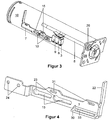
- FIG. 3 shows the relevant parts of the signal plunger 6 of the unspecified here door drive 1.
- the spring energy accumulator 18 opens at a in FIG. 3 right end, ie that of the shutter shaft 2, not shown facing end, for example in a flange plate 28 and is inserted into this.
- the flange plate 28 is used to fasten the spring force accumulator 18 preferably on a gear housing of the door drive 1.
- the signal plunger 6 is stored in the flange plate 28 by means of a guide bush 29 inserted into this linearly stored.
- the guide bushing 29 is designed so that the signal plunger 6 brushes along it in such a way that dirt particles from the outside, ie from the left in FIG. 3 , not through the flange plate 28 through and thus can get into a transmission housing interior.
- the receiving elements 10 are shown, to which the switch receptacle 7 is attached via the elongated holes 15 on the spring force spoke 18 or mounted at least longitudinally movably.
- FIG. 4 shows a perspective view of only the switch receptacle 7 of one with respect to FIG. 3 opposite side, in which the slots 15 are incorporated for receiving the receiving elements 10, not shown here.
- the oblong holes 15 preferably extend in the longitudinal direction of the switch receptacle 7, which corresponds to the direction of movement of the flap carriage 5, also not shown, within the door drive 1.
- the elongated holes 15 terminate in a respective mushroom-shaped formation 23, through which the receiving elements 10, not shown here, can first be passed through in order to clamp in the region of the oblong holes 15, for example.
- the receiving elements 10 may have screw-head-like ends, which may indeed be guided through the mushroom-like formations, but due to the narrower design of the slots 15 abut against the surface of the sheet-like switch receptacle 7.
- the Griffanformung 22 On the opposite side of the thus formed attachment for the electrical switch 3 through the mounting holes 24 is the Griffanformung 22, wherein the switch receptacle 7 is made in one piece by stamped Biegever-drive of a sheet metal component.
- the switch receptacle 7 has a projection 30.
- the projection 30 has in turn a slot 33 inside.
- the slot 33 is used for fixed attachment of the switch receptacle 7 on the door drive 1, on the system support 17 and on the housing of the spring force memory 18th
- through holes 31 are provided. These serve to carry out conventional cable ties, by means of which the connection lines of the electrical switch 3 can be fixed and thus securely laid.
- FIG. 5a shows the arrangement of switch receptacle 7 and exemplary system support 17 in a perspective view obliquely from the front right above with respect to the system carrier 17.
- the slot 33 of the locking projection and a corresponding mounting opening 32 in the system carrier 17 are aligned.
- the electrical switch 3 is hinted at.
- FIG. 5b shows the arrangement of FIG. 5a along a section line A - A in FIG. 5a ,
- the locking of the switch receptacle 7 on the system carrier 17 by means of a locking screw 34 which is inserted from one side through the mounting hole 32 and the slot 33 and bolted at the free end with a nut 35, as indicated by the dashed line.
- the system carrier 17 is in FIGS. 5a and 5b each shown from a top.
- the door drive 1 or its system support 17 is mounted with a bottom, for example on a mounting plate, which in turn is attached, for example, to a lintel. Ie. the top of the system carrier 17 always points to the fitter.
- both the locking screw 34 for screwing and the Griffanformung 22 for moving the switch receptacle 7 are accessible at any time, which facilitates the adjustment of the switch receptacle 16.
- the locking nut 35 is preferably taken captive by means of terminals or the like in the system support 17.
- the locking screw 34 is screwed into the mounting opening 32, for example, self-tapping.
- FIG. 6 shows a perspective view of the signal plunger 6, on which the actuating lug 8 is formed for triggering the trigger element 9 of the electric switch 3, not shown here.
- closer shaft 2 of the door drive 1 end facing the signal plunger 6 has a receiving end 25. The receiving end is used to attach the signal plunger 6 to the flap carriage 5, not shown here.
- FIG. 7 shows the connection of the signal plunger 6 here, for example, to the tab truck 5 from a different perspective.
- the signal plunger 6 is screwed with its receiving end 25 in a correspondingly formed receptacle 21 of the flap carriage 5, but can also be pressed, glued or attached in any other way.
- the attachment of the signal plunger 6 on the tab carriage 5 is rigid, but can also be designed, for example, pivotable. In the case guaranteed the above-described, not shown here guide bush 29, the linear movement of the signal plunger. 6
- a pressure roller 39 rolls on the circumferential surface of a corresponding Hubkurvenance 40 of the door drive 1 by way of example substantially pressed in the direction of signal plunger 6 from. Drucktolle 39 and Hubkurvenin 40 are added freely rotatable in the tab carriage 5.
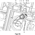
- FIG. 8a an inventive embodiment of an arrangement is now shown an electric switch 3 'within the door drive 1, for reasons of clarity without system support 17.
- the electrical switch 3' is attached via a switch receptacle 16 on the door drive 1.
- the switch receptacle 16 is arranged variably in the door drive 1 preferably along the double arrow shown.
- the electrical switch 3 ' is mounted below the preferably sheet-shaped switch receptacle 16 and has an actuating end, preferably in the form of a triggering element 9', so that at a pressure on the actuating end of the electrical switch 3 'can be triggered.
- a plunger 11 is attached.
- a rocking element 12 is provided, which is received in the door drive 1 so as to be pivotable about a rocking axis 13.
- the rocker axis 13 extends transversely to the direction of movement of the non-visible flap carriage 5 and thus transversely to the compression direction of the closing spring 19th
- the rocker element 12 has a first Betreliistsanformung 26 which is articulated by the plunger 11, and a second Betreliistsanformung 27, which serves to trigger the electrical switch 3 '.
- the Betreliistsanformept 26, 27 are ends of the rocker element 12th
- the rocker element 12 is acted upon by a spring element 14 by way of example in the form of a double leg spring such that the spring element 14 presses the first actuating projection 26 against the plunger 11 or pushes in the direction of the plunger 11.
- the other spring end of the double leg spring is, as in FIG. 8b to recognize, at an inner, down in FIG. 8b pointing surface preferably supported by the system carrier 17.
- the supported on the system support 17 spring ends preferably have a distance to each other, so that between them, a gap is formed in which the second Befest Trentsanformung 27 is arranged and by a in FIG. 8b recognizable passage opening 36 in the system carrier 17 passes freely pivotable.
- the spring element 14 is provided to bring the rocker element 12 with the first Betsch Trentsanformung 26 permanently against the plunger 11 for conditioning, and also extends around the rocking axis 13 around.
- FIG. 8b is the shutter spring 19 to recognize approach.
- the electrical switch 3 ' is similar to the electrical switch 3 now attached to the switch receptacle 16 by means of mounting holes 24'.
- the switch receptacle 16 is provided with fastening means 37, for example in the form of screws.
- the screws are accommodated in oblong holes 38 of the system carrier 17 of the door drive 1.
- the slots 38 extend along the direction of movement of the plunger 11.
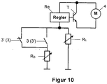
- FIG. 9 shows a schematic diagram of an interconnection of the switch 3, 3 'according to another embodiment of the invention. Additional switching elements such as protective capacitors and the like are omitted for clarity.
- the drive motor 4 can be operated as a generator when closing a door leaf. So that the drive motor 4 does not block the movement of the door leaf, the electrical energy generated by it must be dissipated.
- an adjustable electrical resistance R 1 preferably in the form of a potentiometer.
- the potentiometer offers the possibility of adapting the door drive to the respective conditions on site, for example to the door leaf weight.
- the drive motor 4 is connected in series with a control element, for example in the form of an NPN transistor T, with its collector and emitter terminals.
- the emitter terminal of the transistor T is further coupled to an input of a regulator Re.
- An output of the regulator Re is coupled to the base of the transistor T and thus controls the transistor T.
- Another output of the regulator Re is connected in series with the resistor R 1 , which is connected with its other terminal to ground. Ie. the removal of the electrical energy generated by the drive motor 4 is dissipated via the resistor R 1 , which thus determines the resistance that opposes the drive motor 4 due to its regenerative operation of its own movement and thus the movement of the door leaf; he thus determines the damping effect of the drive motor.
- the resistor R 1 is connected in parallel to a series circuit consisting essentially of the switch 3 and another electrical resistor R 2 , again in the form of a potentiometer.
- the switch 3 is actuated.
- a preferred solution is to increase the driving force of the door drive 4 shortly before reaching the closed position, for example at 7 ° opening angle of the door leaf. This happens because the switch 3 on operation, the resistor R 2 switches.
- the switch 3 ' is connected in a similar manner as an opener, as shown in the left-hand part of the interconnection, the reverse effect can be achieved. Ie. an actuation of the switch 3 'leads to a separation of the electrical connection between now a third electrical resistance R 3 and the controller Re and thus the drive motor 4. This reduces the power that can be dissipated by the resistance circuit; the damping effect of the drive motor 4 increases. This can be used, for example, to reduce the closing speed of the door leaf, so that the risk of injury due to the falling door leaf can be reduced.
- the interconnection according to FIG. 9 is preferably formed such that the normally-open switch 3 is actuated when the door leaf occupies an opening angle smaller and / or equal to a predetermined first opening angle near the closing position.
- the switch 3 ' which is designed as an opener, is actuated when the door leaf occupies an opening angle greater than or equal to a predetermined second opening angle, preferably close to the opening position.
- the regulator Re is designed as a constant voltage regulator, i. H. it controls the voltage applied to the drive motor 4 voltage.
- the resistors R 1 , R 2 , R 3 , R D used can, of course, each be designed as unchangeable electrical resistors.
- the switches 3, 3 ' can now be used to connect or disconnect the drive motor or to connect a respective electrical resistance or to disconnect it electrically from the drive motor.
- the electrical switches 3, 3 ' are identical. Furthermore, it is possible to provide both described switch arrangements on one and the same door drive 1 at the same time. This has the advantage that the switches 3, 3 'can be used to detect once the fully open position and once the fully closed position of the connected door leaf. Alternatively, the switches 3, 3 'can be operated redundantly, so that a switch 3, 3' can fail without impairing the operational safety.
- the invention is of course also applicable to door operators, in which the pressure roller between the closing spring and cam is arranged. In that case, the pressure roller holder is designed to receive the signal plunger 6 in a stationary manner for the electrical switch 3. For the electric switch 3 'this time a push rod is inserted into the closing spring, which actuates the rocking element 12.
- the switches 3, 3 ' are also suitable for closing sequence controls.
- one of the switches 3, 3 ' can be provided for triggering or releasing an exemplary electric locking device, the actuation of which causes blocking or release of the door leaf-side door actuator.
- the other switch 3 ', 3 can be used to detect the fully open position of the passive leaf, for example, to shut off a drive motor 4.
Claims (11)
- Actionneur de porte (1), aménagé à pivoter un vantail de porte en au moins une direction, avec• une unité d'entraînement (4, 5, 18), et• un arbre de fermeture (2) pour l'actionnement du vantail de porte, lequel arbre est entraîné par l'intermédiaire d'une connexion opérationnelle mécanique à l'unité d'entraînement (4, 5, 18) par l'unité d'entraînement en ladite au moins une direction, dans lequel• la connexion opérationnelle mécanique présente au moins un élément (5), lequel exécute un mouvement lors de l'entraînement de l'arbre de fermeture (2) par l'intermédiaire de l'unité d'entraînement (4, 5, 18), et• un commutateur (3') électrique est prévu, lequel est actionné mécaniquement par l'intermédiaire de l'élément (5) déplaçable de telle façon qu'une information électrique sur une position ouverte du vantail tournant est mise à disposition, dans lequel• le mouvement dudit au moins un élément (5) est un mouvement linéaire,• dans lequel l'unité d'entraînement (4, 5, 18) présente par ailleurs un accumulateur d'énergie de ressort (18) avec un ressort de fermeture (19), lequel- est connecté opérationnellement à l'arbre de fermeture (2),- est mis en tension par l'intermédiaire d'un mouvement d'ouverture du vantail de porte, et- est détendu par l'intermédiaire d'un mouvement de fermeture du vantail de porte,• dans lequel la connexion opérationnelle mécanique est branchée entre le ressort de fermeture (19) et l'arbre de fermeture (2),• dans lequel l'élément (5) déplaçable est aménagé au moyen d'un chariot à éclisses (5), lequel est mécaniquement connecté opérationnellement à une tige, laquelle s'étend à travers le ressort de fermeture (19),• dans lequel accumulateur d'énergie de ressort (18) s'étend le long de la direction du mouvement du chariot à éclisses (5), respectivement de la tige,caractérisé en ce que• dans la région d'une extrémité libre de la tige et détournée du chariot à éclisses (5) est agencé un poussoir (11), lequel coopère avec le commutateur électrique (3'), dans lequel• la connexion opérationnelle entre le poussoir (11) et le commutateur électrique (3') comporte un élément basculant (12), lequel est accommodé de façon pivotable en un axe basculant (13) dans l'actionneur de porte (1),• dans lequel l'élément basculant (12) comprend une première conformation d'actionnement (26), laquelle est articulable par l'intermédiaire du poussoir (11),• l'élément basculant (12) comprend une deuxième conformation d'actionnement (27), laquelle sert au déclenchement du commutateur électrique (3').
- Actionneur de porte (1) selon la revendication 1, caractérisé en ce que l'unité d'entraînement (4, 5, 18) présente par ailleurs un moteur d'entraînement électrique (4).
- Actionneur de porte (1) selon la revendication 2, caractérisé en ce que le commutateur électrique (3') est couplé de telle façon au moteur d'entraînement (4) que le commutateur électrique (3'), lors d'un actionnement du moteur d'entraînement (4), se déconnecte à une position d'ouverture prédéterminée du vantail de porte.
- Actionneur de porte (1) selon la revendication 2, caractérisé en ce que• le moteur d'entraînement (4), lors de l'entraînement du vantail de porte en ladite au moins une direction, est opéré de façon génératrice, de sorte que le moteur d'entraînement (4) oppose une résistance prédéterminée au mouvement du vantail de porte, et• le commutateur électrique (3') est interconnecté de telle façon au moteur d'entraînement (4) que, lors d'un actionnement du commutateur électrique (3'), la résistance prédéterminée du moteur d'entraînement est changée.
- Actionneur de porte (1) selon la revendication 4, caractérisé en ce que le commutateur électrique (3') est connecté en série entre une résistance de charge (R2) et le moteur d'entraînement (4).
- Actionneur de porte (1) selon l'une des revendications 3 à 5, caractérisé en ce que l'actionnement du commutateur électrique (3') se fait dans la butée terminale du vantail de porte.
- Actionneur de porte (1) selon la revendication 1, caractérisé en ce que• le commutateur électrique (3') est accommodé dans l'actionneur de porte (1) au moyen d'une réception de commutateur (16), et• la réception de commutateur (16) avec le commutateur électrique (3') est ajustable en une position en relation à l'élément basculant (12), dans lequel une position respective du commutateur électrique (3') par rapport à l'élément basculant (12) correspond à un angle d'ouverture associé du vantail de porte.
- Actionneur de porte (1) selon la revendication 7, caractérisé en ce que l'élément basculant (12) est mis sous prétension au moyen d'un élément de ressort (14) autour de l'axe basculant (13) de telle façon que la première conformation d'actionnement (26) est pressée en direction du poussoir (11).
- Actionneur de porte (1) selon l'une des revendications 7 à 8, caractérisé en ce que la réception de commutateur (16)• est agencé de façon stationnaire sur un support de système (17) de l'actionneur de porte (1), et• est ajustable avec le commutateur électrique (3') en direction d'un mouvement du poussoir (11), dans lequel une position respective du commutateur électrique (3') par rapport à l'élément basculant (12) correspond à un angle d'ouverture associé du vantail de porte.
- Actionneur de porte (1) selon l'une des revendications mentionnées ci-avant, caractérisé en ce que• l'actionneur de porte (1) présente un dispositif de maintien ouvert, avec lequel le vantail de porte peut être maintenu ouvert en une position d'ouverture, et• un actionnement du dispositif de maintien ouvert est piloté par l'intermédiaire du commutateur électrique (3').
- Actionneur de porte (1) selon l'une des revendications mentionnées ci-avant, caractérisé en ce que• l'actionneur de porte (1) présente un support de système (17) pour l'aménagement de la structure de base de celui-ci, et au moins ledit commutateur électrique (3'), la réception de commutateur (7, 16) et/ou l'élément basculant (12) est attaché(e)/sont attachés sur le support de système.
Applications Claiming Priority (1)
| Application Number | Priority Date | Filing Date | Title |
|---|---|---|---|
| DE102009004505A DE102009004505A1 (de) | 2009-01-09 | 2009-01-09 | Türbetätiger zur Betätigung eines Türblattes |
Publications (3)
| Publication Number | Publication Date |
|---|---|
| EP2206867A2 EP2206867A2 (fr) | 2010-07-14 |
| EP2206867A3 EP2206867A3 (fr) | 2014-05-14 |
| EP2206867B1 true EP2206867B1 (fr) | 2018-08-22 |
Family
ID=42104694
Family Applications (1)
| Application Number | Title | Priority Date | Filing Date |
|---|---|---|---|
| EP10000055.3A Active EP2206867B1 (fr) | 2009-01-09 | 2010-01-07 | Actionneur de porte destiné à l'actionnement d'un vantail |
Country Status (2)
| Country | Link |
|---|---|
| EP (1) | EP2206867B1 (fr) |
| DE (1) | DE102009004505A1 (fr) |
Cited By (1)
| Publication number | Priority date | Publication date | Assignee | Title |
|---|---|---|---|---|
| CN111021874A (zh) * | 2019-12-09 | 2020-04-17 | 国网智能科技股份有限公司 | 一种隧道防火门及相关的自检方法和防火方法 |
Families Citing this family (2)
| Publication number | Priority date | Publication date | Assignee | Title |
|---|---|---|---|---|
| DE102012103210A1 (de) | 2012-04-13 | 2013-10-17 | Gu Automatic Gmbh | Einrichtung zur Schließfolgeregelung einer selbstschließenden zweiflügligen Tür sowie ein Verfahren zur Schließregelung einer selbstschließenden Tür und Feuerschutztür mit einer Einrichtung zur Schließfolgeregelung |
| CN108625750B (zh) * | 2018-05-18 | 2023-06-27 | 郑州金特莱电子有限公司 | 一种用于监控防火门的全自动开闭门器 |
Family Cites Families (5)
| Publication number | Priority date | Publication date | Assignee | Title |
|---|---|---|---|---|
| US3210065A (en) * | 1962-10-17 | 1965-10-05 | Crown Ind Inc | Hydraulic door opener |
| US4614059A (en) * | 1985-07-01 | 1986-09-30 | Trampe Douglas R | Automatic window |
| US5193647A (en) * | 1992-03-23 | 1993-03-16 | Thomas Industries, Inc. | Easy opening door control device |
| US5651162A (en) * | 1996-01-04 | 1997-07-29 | Keszthelyi; Laszlo | Hydraulic door control system |
| US7234201B2 (en) * | 2003-07-18 | 2007-06-26 | Jackson Corporation | Door closer power adjusting device |
-
2009
- 2009-01-09 DE DE102009004505A patent/DE102009004505A1/de not_active Withdrawn
-
2010
- 2010-01-07 EP EP10000055.3A patent/EP2206867B1/fr active Active
Non-Patent Citations (1)
| Title |
|---|
| None * |
Cited By (1)
| Publication number | Priority date | Publication date | Assignee | Title |
|---|---|---|---|---|
| CN111021874A (zh) * | 2019-12-09 | 2020-04-17 | 国网智能科技股份有限公司 | 一种隧道防火门及相关的自检方法和防火方法 |
Also Published As
| Publication number | Publication date |
|---|---|
| EP2206867A3 (fr) | 2014-05-14 |
| EP2206867A2 (fr) | 2010-07-14 |
| DE102009004505A1 (de) | 2010-07-15 |
Similar Documents
| Publication | Publication Date | Title |
|---|---|---|
| EP2318624B1 (fr) | Mécanisme d'ouverture de porte à réglage automatique du pêne d'ouverture | |
| EP3697999A1 (fr) | Dispositif d'installation pour une portière de véhicule automobile | |
| DE102009006948B4 (de) | Vorrichtung und Verfahren zur elektromotorischen Betätigung einer Tür | |
| EP2225430B1 (fr) | Dispositif de verrouillage d'une porte | |
| EP1550784B1 (fr) | Dispositif d'entraînement de gâche pour une serrure de véhicule | |
| DE102006028875B3 (de) | Vorrichtung zur Schließfolgeregelung für zweiflügelige Drehtüren | |
| WO2018137839A1 (fr) | Agencement de poignée de porte pour porte de véhicule | |
| WO2018137837A1 (fr) | Ensemble poignée de porte pour une portière de véhicule | |
| DE102012111085B4 (de) | Türöffner | |
| EP0911471A2 (fr) | Dispositif d'arrêt pour deux éléments montés de manière pivotante | |
| EP2206867B1 (fr) | Actionneur de porte destiné à l'actionnement d'un vantail | |
| EP1865130B1 (fr) | Agencement de déverrouillage d'une fenêtre, d'une porte ou analogue | |
| DE102009004498B4 (de) | Türanordnung mit einer Schließfolgeregelung | |
| WO2012095090A1 (fr) | Garniture pour actionneur de porte battante | |
| EP1870553B1 (fr) | Dispositif destiné à la fermeture conséquente de portes rotatives à deux battants | |
| EP3325751A1 (fr) | Entraînement d'un battant pivotant | |
| DE102007055354B4 (de) | Feststellvorrichtung für einen Türschließer | |
| DE102008013494A1 (de) | Türschließer | |
| DE19532263B4 (de) | Vorrichtung zur Schließfolgeregelung für zweiflügelige Türen | |
| EP1580360B1 (fr) | Actionneur pour véhicules automobiles | |
| DE102021204341B3 (de) | Türantrieb | |
| DE102006041922B4 (de) | Feststeller für ein schwenkbares Bauteil, insbesondere eine Fahrzeugtür | |
| DE19723174C2 (de) | Elektrisch betriebener Sicherheitsverschluß mit zusätzlichem Betätigungsantrieb für Türen und Fenster | |
| EP0899403A1 (fr) | Dispositif entrebâilleur pour éléments montés de façon pivotante | |
| WO2024002616A1 (fr) | Charnière de porte pliante et unité fonctionnelle comprenant une porte pliante |
Legal Events
| Date | Code | Title | Description |
|---|---|---|---|
| PUAI | Public reference made under article 153(3) epc to a published international application that has entered the european phase |
Free format text: ORIGINAL CODE: 0009012 |
|
| AK | Designated contracting states |
Kind code of ref document: A2 Designated state(s): AT BE BG CH CY CZ DE DK EE ES FI FR GB GR HR HU IE IS IT LI LT LU LV MC MK MT NL NO PL PT RO SE SI SK SM TR |
|
| AX | Request for extension of the european patent |
Extension state: AL BA RS |
|
| RAP1 | Party data changed (applicant data changed or rights of an application transferred) |
Owner name: DORMA GMBH + CO. KG |
|
| PUAL | Search report despatched |
Free format text: ORIGINAL CODE: 0009013 |
|
| AK | Designated contracting states |
Kind code of ref document: A3 Designated state(s): AT BE BG CH CY CZ DE DK EE ES FI FR GB GR HR HU IE IS IT LI LT LU LV MC MK MT NL NO PL PT RO SE SI SK SM TR |
|
| AX | Request for extension of the european patent |
Extension state: AL BA RS |
|
| RIC1 | Information provided on ipc code assigned before grant |
Ipc: E05F 15/12 20060101AFI20140407BHEP Ipc: E05F 15/10 20060101ALI20140407BHEP Ipc: E05F 3/10 20060101ALI20140407BHEP |
|
| 17P | Request for examination filed |
Effective date: 20141111 |
|
| RBV | Designated contracting states (corrected) |
Designated state(s): AT BE BG CH CY CZ DE DK EE ES FI FR GB GR HR HU IE IS IT LI LT LU LV MC MK MT NL NO PL PT RO SE SI SK SM TR |
|
| RAP1 | Party data changed (applicant data changed or rights of an application transferred) |
Owner name: DORMA DEUTSCHLAND GMBH |
|
| REG | Reference to a national code |
Ref country code: DE Ref legal event code: R079 Ref document number: 502010015278 Country of ref document: DE Free format text: PREVIOUS MAIN CLASS: E05F0015120000 Ipc: E05F0015603000 |
|
| RIC1 | Information provided on ipc code assigned before grant |
Ipc: E05F 15/611 20150101ALI20160119BHEP Ipc: E05F 15/603 20150101AFI20160119BHEP |
|
| 17Q | First examination report despatched |
Effective date: 20160202 |
|
| STAA | Information on the status of an ep patent application or granted ep patent |
Free format text: STATUS: EXAMINATION IS IN PROGRESS |
|
| RAP1 | Party data changed (applicant data changed or rights of an application transferred) |
Owner name: DORMAKABA DEUTSCHLAND GMBH |
|
| GRAP | Despatch of communication of intention to grant a patent |
Free format text: ORIGINAL CODE: EPIDOSNIGR1 |
|
| STAA | Information on the status of an ep patent application or granted ep patent |
Free format text: STATUS: GRANT OF PATENT IS INTENDED |
|
| INTG | Intention to grant announced |
Effective date: 20180315 |
|
| GRAS | Grant fee paid |
Free format text: ORIGINAL CODE: EPIDOSNIGR3 |
|
| GRAA | (expected) grant |
Free format text: ORIGINAL CODE: 0009210 |
|
| STAA | Information on the status of an ep patent application or granted ep patent |
Free format text: STATUS: THE PATENT HAS BEEN GRANTED |
|
| AK | Designated contracting states |
Kind code of ref document: B1 Designated state(s): AT BE BG CH CY CZ DE DK EE ES FI FR GB GR HR HU IE IS IT LI LT LU LV MC MK MT NL NO PL PT RO SE SI SK SM TR |
|
| REG | Reference to a national code |
Ref country code: GB Ref legal event code: FG4D Free format text: NOT ENGLISH |
|
| REG | Reference to a national code |
Ref country code: CH Ref legal event code: EP |
|
| REG | Reference to a national code |
Ref country code: AT Ref legal event code: REF Ref document number: 1032731 Country of ref document: AT Kind code of ref document: T Effective date: 20180915 |
|
| REG | Reference to a national code |
Ref country code: IE Ref legal event code: FG4D Free format text: LANGUAGE OF EP DOCUMENT: GERMAN |
|
| REG | Reference to a national code |
Ref country code: DE Ref legal event code: R096 Ref document number: 502010015278 Country of ref document: DE |
|
| REG | Reference to a national code |
Ref country code: NL Ref legal event code: MP Effective date: 20180822 |
|
| REG | Reference to a national code |
Ref country code: LT Ref legal event code: MG4D |
|
| PG25 | Lapsed in a contracting state [announced via postgrant information from national office to epo] |
Ref country code: GR Free format text: LAPSE BECAUSE OF FAILURE TO SUBMIT A TRANSLATION OF THE DESCRIPTION OR TO PAY THE FEE WITHIN THE PRESCRIBED TIME-LIMIT Effective date: 20181123 Ref country code: NO Free format text: LAPSE BECAUSE OF FAILURE TO SUBMIT A TRANSLATION OF THE DESCRIPTION OR TO PAY THE FEE WITHIN THE PRESCRIBED TIME-LIMIT Effective date: 20181122 Ref country code: BG Free format text: LAPSE BECAUSE OF FAILURE TO SUBMIT A TRANSLATION OF THE DESCRIPTION OR TO PAY THE FEE WITHIN THE PRESCRIBED TIME-LIMIT Effective date: 20181122 Ref country code: SE Free format text: LAPSE BECAUSE OF FAILURE TO SUBMIT A TRANSLATION OF THE DESCRIPTION OR TO PAY THE FEE WITHIN THE PRESCRIBED TIME-LIMIT Effective date: 20180822 Ref country code: FI Free format text: LAPSE BECAUSE OF FAILURE TO SUBMIT A TRANSLATION OF THE DESCRIPTION OR TO PAY THE FEE WITHIN THE PRESCRIBED TIME-LIMIT Effective date: 20180822 Ref country code: LT Free format text: LAPSE BECAUSE OF FAILURE TO SUBMIT A TRANSLATION OF THE DESCRIPTION OR TO PAY THE FEE WITHIN THE PRESCRIBED TIME-LIMIT Effective date: 20180822 Ref country code: IS Free format text: LAPSE BECAUSE OF FAILURE TO SUBMIT A TRANSLATION OF THE DESCRIPTION OR TO PAY THE FEE WITHIN THE PRESCRIBED TIME-LIMIT Effective date: 20181222 Ref country code: NL Free format text: LAPSE BECAUSE OF FAILURE TO SUBMIT A TRANSLATION OF THE DESCRIPTION OR TO PAY THE FEE WITHIN THE PRESCRIBED TIME-LIMIT Effective date: 20180822 |
|
| PG25 | Lapsed in a contracting state [announced via postgrant information from national office to epo] |
Ref country code: ES Free format text: LAPSE BECAUSE OF FAILURE TO SUBMIT A TRANSLATION OF THE DESCRIPTION OR TO PAY THE FEE WITHIN THE PRESCRIBED TIME-LIMIT Effective date: 20180822 Ref country code: LV Free format text: LAPSE BECAUSE OF FAILURE TO SUBMIT A TRANSLATION OF THE DESCRIPTION OR TO PAY THE FEE WITHIN THE PRESCRIBED TIME-LIMIT Effective date: 20180822 Ref country code: HR Free format text: LAPSE BECAUSE OF FAILURE TO SUBMIT A TRANSLATION OF THE DESCRIPTION OR TO PAY THE FEE WITHIN THE PRESCRIBED TIME-LIMIT Effective date: 20180822 |
|
| PG25 | Lapsed in a contracting state [announced via postgrant information from national office to epo] |
Ref country code: EE Free format text: LAPSE BECAUSE OF FAILURE TO SUBMIT A TRANSLATION OF THE DESCRIPTION OR TO PAY THE FEE WITHIN THE PRESCRIBED TIME-LIMIT Effective date: 20180822 Ref country code: PL Free format text: LAPSE BECAUSE OF FAILURE TO SUBMIT A TRANSLATION OF THE DESCRIPTION OR TO PAY THE FEE WITHIN THE PRESCRIBED TIME-LIMIT Effective date: 20180822 Ref country code: IT Free format text: LAPSE BECAUSE OF FAILURE TO SUBMIT A TRANSLATION OF THE DESCRIPTION OR TO PAY THE FEE WITHIN THE PRESCRIBED TIME-LIMIT Effective date: 20180822 Ref country code: RO Free format text: LAPSE BECAUSE OF FAILURE TO SUBMIT A TRANSLATION OF THE DESCRIPTION OR TO PAY THE FEE WITHIN THE PRESCRIBED TIME-LIMIT Effective date: 20180822 Ref country code: CZ Free format text: LAPSE BECAUSE OF FAILURE TO SUBMIT A TRANSLATION OF THE DESCRIPTION OR TO PAY THE FEE WITHIN THE PRESCRIBED TIME-LIMIT Effective date: 20180822 |
|
| REG | Reference to a national code |
Ref country code: DE Ref legal event code: R097 Ref document number: 502010015278 Country of ref document: DE |
|
| PG25 | Lapsed in a contracting state [announced via postgrant information from national office to epo] |
Ref country code: SK Free format text: LAPSE BECAUSE OF FAILURE TO SUBMIT A TRANSLATION OF THE DESCRIPTION OR TO PAY THE FEE WITHIN THE PRESCRIBED TIME-LIMIT Effective date: 20180822 Ref country code: DK Free format text: LAPSE BECAUSE OF FAILURE TO SUBMIT A TRANSLATION OF THE DESCRIPTION OR TO PAY THE FEE WITHIN THE PRESCRIBED TIME-LIMIT Effective date: 20180822 Ref country code: SM Free format text: LAPSE BECAUSE OF FAILURE TO SUBMIT A TRANSLATION OF THE DESCRIPTION OR TO PAY THE FEE WITHIN THE PRESCRIBED TIME-LIMIT Effective date: 20180822 |
|
| PLBE | No opposition filed within time limit |
Free format text: ORIGINAL CODE: 0009261 |
|
| STAA | Information on the status of an ep patent application or granted ep patent |
Free format text: STATUS: NO OPPOSITION FILED WITHIN TIME LIMIT |
|
| 26N | No opposition filed |
Effective date: 20190523 |
|
| PG25 | Lapsed in a contracting state [announced via postgrant information from national office to epo] |
Ref country code: MC Free format text: LAPSE BECAUSE OF FAILURE TO SUBMIT A TRANSLATION OF THE DESCRIPTION OR TO PAY THE FEE WITHIN THE PRESCRIBED TIME-LIMIT Effective date: 20180822 Ref country code: SI Free format text: LAPSE BECAUSE OF FAILURE TO SUBMIT A TRANSLATION OF THE DESCRIPTION OR TO PAY THE FEE WITHIN THE PRESCRIBED TIME-LIMIT Effective date: 20180822 |
|
| REG | Reference to a national code |
Ref country code: CH Ref legal event code: PL |
|
| GBPC | Gb: european patent ceased through non-payment of renewal fee |
Effective date: 20190107 |
|
| PG25 | Lapsed in a contracting state [announced via postgrant information from national office to epo] |
Ref country code: LU Free format text: LAPSE BECAUSE OF NON-PAYMENT OF DUE FEES Effective date: 20190107 |
|
| REG | Reference to a national code |
Ref country code: BE Ref legal event code: MM Effective date: 20190131 |
|
| REG | Reference to a national code |
Ref country code: IE Ref legal event code: MM4A |
|
| PG25 | Lapsed in a contracting state [announced via postgrant information from national office to epo] |
Ref country code: FR Free format text: LAPSE BECAUSE OF NON-PAYMENT OF DUE FEES Effective date: 20190131 |
|
| PG25 | Lapsed in a contracting state [announced via postgrant information from national office to epo] |
Ref country code: BE Free format text: LAPSE BECAUSE OF NON-PAYMENT OF DUE FEES Effective date: 20190131 |
|
| PG25 | Lapsed in a contracting state [announced via postgrant information from national office to epo] |
Ref country code: CH Free format text: LAPSE BECAUSE OF NON-PAYMENT OF DUE FEES Effective date: 20190131 Ref country code: GB Free format text: LAPSE BECAUSE OF NON-PAYMENT OF DUE FEES Effective date: 20190107 Ref country code: LI Free format text: LAPSE BECAUSE OF NON-PAYMENT OF DUE FEES Effective date: 20190131 |
|
| PG25 | Lapsed in a contracting state [announced via postgrant information from national office to epo] |
Ref country code: IE Free format text: LAPSE BECAUSE OF NON-PAYMENT OF DUE FEES Effective date: 20190107 |
|
| REG | Reference to a national code |
Ref country code: AT Ref legal event code: MM01 Ref document number: 1032731 Country of ref document: AT Kind code of ref document: T Effective date: 20190107 |
|
| PG25 | Lapsed in a contracting state [announced via postgrant information from national office to epo] |
Ref country code: TR Free format text: LAPSE BECAUSE OF FAILURE TO SUBMIT A TRANSLATION OF THE DESCRIPTION OR TO PAY THE FEE WITHIN THE PRESCRIBED TIME-LIMIT Effective date: 20180822 |
|
| PG25 | Lapsed in a contracting state [announced via postgrant information from national office to epo] |
Ref country code: AT Free format text: LAPSE BECAUSE OF NON-PAYMENT OF DUE FEES Effective date: 20190107 |
|
| PG25 | Lapsed in a contracting state [announced via postgrant information from national office to epo] |
Ref country code: PT Free format text: LAPSE BECAUSE OF FAILURE TO SUBMIT A TRANSLATION OF THE DESCRIPTION OR TO PAY THE FEE WITHIN THE PRESCRIBED TIME-LIMIT Effective date: 20181222 Ref country code: MT Free format text: LAPSE BECAUSE OF FAILURE TO SUBMIT A TRANSLATION OF THE DESCRIPTION OR TO PAY THE FEE WITHIN THE PRESCRIBED TIME-LIMIT Effective date: 20180822 |
|
| PG25 | Lapsed in a contracting state [announced via postgrant information from national office to epo] |
Ref country code: CY Free format text: LAPSE BECAUSE OF FAILURE TO SUBMIT A TRANSLATION OF THE DESCRIPTION OR TO PAY THE FEE WITHIN THE PRESCRIBED TIME-LIMIT Effective date: 20180822 |
|
| PG25 | Lapsed in a contracting state [announced via postgrant information from national office to epo] |
Ref country code: HU Free format text: LAPSE BECAUSE OF FAILURE TO SUBMIT A TRANSLATION OF THE DESCRIPTION OR TO PAY THE FEE WITHIN THE PRESCRIBED TIME-LIMIT; INVALID AB INITIO Effective date: 20100107 |
|
| PG25 | Lapsed in a contracting state [announced via postgrant information from national office to epo] |
Ref country code: MK Free format text: LAPSE BECAUSE OF FAILURE TO SUBMIT A TRANSLATION OF THE DESCRIPTION OR TO PAY THE FEE WITHIN THE PRESCRIBED TIME-LIMIT Effective date: 20180822 |
|
| PGFP | Annual fee paid to national office [announced via postgrant information from national office to epo] |
Ref country code: DE Payment date: 20240119 Year of fee payment: 15 |