EP1868750B1 - Method for straightening an eccentric shaft - Google Patents
Method for straightening an eccentric shaft Download PDFInfo
- Publication number
- EP1868750B1 EP1868750B1 EP06739752A EP06739752A EP1868750B1 EP 1868750 B1 EP1868750 B1 EP 1868750B1 EP 06739752 A EP06739752 A EP 06739752A EP 06739752 A EP06739752 A EP 06739752A EP 1868750 B1 EP1868750 B1 EP 1868750B1
- Authority
- EP
- European Patent Office
- Prior art keywords
- shaft
- crankshaft
- rollers
- compressive force
- intersection
- Prior art date
- Legal status (The legal status is an assumption and is not a legal conclusion. Google has not performed a legal analysis and makes no representation as to the accuracy of the status listed.)
- Not-in-force
Links
Images


Classifications
-
- B—PERFORMING OPERATIONS; TRANSPORTING
- B21—MECHANICAL METAL-WORKING WITHOUT ESSENTIALLY REMOVING MATERIAL; PUNCHING METAL
- B21D—WORKING OR PROCESSING OF SHEET METAL OR METAL TUBES, RODS OR PROFILES WITHOUT ESSENTIALLY REMOVING MATERIAL; PUNCHING METAL
- B21D3/00—Straightening or restoring form of metal rods, metal tubes, metal profiles, or specific articles made therefrom, whether or not in combination with sheet metal parts
- B21D3/16—Straightening or restoring form of metal rods, metal tubes, metal profiles, or specific articles made therefrom, whether or not in combination with sheet metal parts of specific articles made from metal rods, tubes, or profiles, e.g. crankshafts, by specially adapted methods or means
-
- B—PERFORMING OPERATIONS; TRANSPORTING
- B21—MECHANICAL METAL-WORKING WITHOUT ESSENTIALLY REMOVING MATERIAL; PUNCHING METAL
- B21K—MAKING FORGED OR PRESSED METAL PRODUCTS, e.g. HORSE-SHOES, RIVETS, BOLTS OR WHEELS
- B21K1/00—Making machine elements
- B21K1/06—Making machine elements axles or shafts
- B21K1/08—Making machine elements axles or shafts crankshafts
-
- B—PERFORMING OPERATIONS; TRANSPORTING
- B23—MACHINE TOOLS; METAL-WORKING NOT OTHERWISE PROVIDED FOR
- B23P—METAL-WORKING NOT OTHERWISE PROVIDED FOR; COMBINED OPERATIONS; UNIVERSAL MACHINE TOOLS
- B23P17/00—Metal-working operations, not covered by a single other subclass or another group in this subclass
Definitions
- This invention relates to a method for straightening eccentric shafts of the type used in internal combustion engines, such as camshafts or crankshafts, especially previously hardened shafts, by deep fillet rolling.
- Eccentric shafts are made for a variety of uses.
- One of the most common uses is in internal combustion engines.
- the power is generated within a plurality of cylinders by reciprocating pistons which, depending on the combustion cycle employed, compress air or a combustible mixture of fuel and air for subsequent ignition.
- the pistons follow a reciprocating axial path, and are connected on a side opposite to their combustion face to connecting rods.
- the connecting rods are in turn connected to an eccentric shaft, the crankshaft.
- the crankshaft is used to translate the axial reciprocating motion of the pistons into rotational motion.
- the pressures generated by combustion in the cylinder acting through this rotational motion create the power output of the engine.
- Another eccentric shaft, the camshaft is typically used in internal combustion engines to control the timing of the intake and exhaust valves in the cylinders.
- Eccentric shafts are required to withstand both high torsional loading, as well as millions of load cycles. For this reason eccentric shafts are usually made of strong and ductile materials, such as steel, and are often hardened for added strength, either by cold working, or by heat treating, or by induction hardening the eccentric shaft to change the crystalline structure of the metal in the high load concentration areas to increase strength.
- the straightness of the eccentric shaft is critical to its operation, partly because it has to fit within the engine structure and partly because a lack of straightness can cause severe vibration. Straightness also gives the eccentric shaft good balance for rotation and reduces torsional vibrations.
- Induction hardening is a widely used process for the surface hardening of steel eccentric shafts.
- a crankshaft is heated by alternating magnetic fields to a temperature within or above the transformation range of steel, followed by immediate quenching.
- the core of the crankshaft remains unaffected by the treatment, and its physical properties are those of the material it was initially formed in, but the hardness of the case is considerably increased by residual compressive stresses in the material, a result of quenching.
- Eccentric shafts oftentimes may develop excessive run-out, or axial misalignment, partly as a result of residual stresses from the machining and induction hardening operations. In such cases, the run-out renders a part non-conforming to the eccentric shaft specifications, potentially resulting in scrap of a relatively expensive component. This is particularly important in a high volume production process because the material rejected increases cycle time and rework cost, as well as scrap rates.
- the traditional method to straighten induction-hardened eccentric shafts is to straighten them using a press straightener to impart a load in a single plane to the eccentric shaft.
- the resulting deflection of the eccentric shaft may push a portion of the hardened case out of compression and into tension, thus locally lowering the strength of the shaft.
- eccentric shafts such as engine crankshafts and camshafts, and especially induction-hardened crankshafts and camshafts, without compromising their strength.
- the JP 11 333520 A discloses a straightening method without lowering the fatigue strength is fillet parts by cold roll-working.
- the US 5,333,480 discloses a truing operation for straightening out of true work pieces such as crankshafts, wherein the fatigue strength of the work piece achieved in a previous strengthening operation must not again be reduced.
- This is achieved by a truing operation, wherein locally bounded compressive residual stresses are induced in a surface layer zone of the work piece by a hardening operation, whereby the respective out of true deformation of the work piece is at least reduced.
- the truing operation is repeated until the out of true deformation is eliminated.
- the compressive residual stresses are induced in a surface layer zone of the work piece by a locally limited hardening operation, e.g. a surface strengthening rolling operation.
- any out of true deformation may be even completely eliminated.
- one roller is pressed against the notch or shoulder area, for example a transition concave fillet of the circumferential surface of the crankshaft end or a shoulder area.
- the present invention is directed to a method for straightening eccentric shafts, such as engine crankshafts or a camshafts, according to claim 1.
- the following describes a method of straightening a hardened eccentric shaft for an internal combustion engine, such as a crankshaft or camshaft, by the use of a selectively-programmed deep rolling machine.
- An induction hardened shaft has regions where the material of the shaft is steel having a martensitic structure. Martensite is the hard constituent that is the chief component of quenched steel.
- a typical crankshaft is shown in FIG. 1 .
- This crankshaft is configured for use in a V-8 internal combustion engine, preferably a diesel engine, but the advantages of this invention can be realized when used not only on a crankshaft resembling the one shown, but any eccentric shaft, such as a crankshaft or a camshaft, used on any engine or machine.
- a crankshaft 100 typically includes at one end, a cylindrical front seal surface 105 to engage a conventional front seal (not shown) disposed on a front side of an engine.
- a rear seal surface 109 similarly provides engagement of a conventional rear crankshaft seal (not shown) disposed on a rear side of the engine.
- crankshaft 100 has five main journals 103 which engage in a conventional manner main bearings (not shown) in the crankcase (not shown) to support the crankshaft 100, and four crankthrows or crankpins 101 to which conventional connecting rods (not shown) are connected to input the power from the pistons to the crankshaft 100.
- main bearings not shown
- crankpins 101 Disposed between and separating the crankpins 101 from the main journals 103 are counterweights 119 which form the walls between the main journals 103 and the crankpins 101.
- the crankshaft 100 further has a front target 107 and a rear target 111 identifying the centers of the front journal 105 and the rear journal 109 respectively defining an imaginary centerline 113 through the crankshaft 100, and providing points of engagement with a deep rolling machine 300 (shown in FIG. 3A ).
- the crankshaft centerline 113 is a straight line coinciding with the axis of rotation extending between the front target 107 and rear target 111.
- FIG. 2 A detailed view of the intersection between two adjacent counterweights 119 around one crankpin 101 is shown in FIG. 2 .
- a continuous peripheral groove or fillet 201 can be seen on either side of the crankpin 101, the groove 201 having a smooth radius blending into the counterweight 119. Similar grooves are found on either side of each crankpin 101.
- a similar continuous peripheral groove 203 is located between each main journal 103 and the adjacent counterweight 119.
- Each of the grooves 201, 203 is located in a stress concentration area on the crankshaft 100 during operation, and is intended to alleviate the stresses going through it during engine operation. These grooves are manufactured to provide residual compressive stresses as a result of the induction hardening operation in the surface in these areas, to help offset tensile stresses that occur during operation.
- crankshafts that undergo hardening develop problems with the straightness of their centerlines.
- This invention presents a method to straighten the centerline 113 of a crankshaft 100, without compromising the residual compressive stresses provided in each groove 201, 203, after the crankshaft 100 has undergone an induction hardening process.
- Traditional hardening operations for crankshafts for example deep fillet rolling, cause the metal crystals in the material to elongate and work harden. In the case where induction hardening is used, the metal structure is martensitic and behaves differently when subjected to loading.
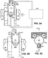
- a deep rolling machine 300 which holds and rotates the crankshaft 100 about the axis between the targets 107 and 111, has appropriate crankpin structures 305 with rollers 303 running in each crankpin groove 201, and is able to follow each crankpin 101 in its orbit as the crankshaft 100 rotates about its centerline 113 without losing contact between the rollers 303 and the grooves 201 is used to straighten the induction hardened shaft, as shown in FIG. 3A .
- an appropriate support structure 307 with rollers 308 is provided to run on the body of the crankpin 309 without losing contact between the rollers 308 and the body of the crankpin 309.
- the deep roller machine 300 is a typical machine known in the art for deep rolling of fillets in crankshafts for hardening the crankshaft by cold working the material, such as the software driven, electronically-controlled deep fillet rolling machine illustrated in U.S. Patent No. 5,493,761 , which is incorporated herein by reference.
- the deep roller machine 300 used for this invention is capable of imparting through the rollers 303 a compressive force 301 to the grooves 201 of the crankshaft.
- the application of the compressive force 301 to the grooves 201 is arranged to act only for a predetermined angle of rotation of the crankshaft 100 as it rotates in the deep rolling machine 300.
- the rollers 308 ride against the central portion of the crankpin between the rollers to resist and divide the radial (relative to the crankpin) component of the compressive force 301. This resistance and division of the compressive force 301 is made possible by forcible engagement of the grooves 201.
- the compressive force 301 is the force that causes the crankshaft 100 to deform in the section clamped by the machine 300, in this case, the crankpin 101.
- the rotational orientation of the crankshaft 100 in the machine 300 is advantageously controlled and known.
- the compressive force 301 acts during the time when the crankpin 101 is substantially at or approaching a position adjacent rotationally to a predetermined rotational position offset relative to a Top Dead Center (TDC) known mounting rotational position, and the rollers 303 are substantially at, or ramping up or down from, a position rotationally opposed to a corresponding Bottom Dead Center (BDC) location of the crankpin 101, as is shown in FIG. 3B and FIG. 3C .
- TDC Top Dead Center
- BDC Bottom Dead Center
- each compressive force 301 Through the application of each compressive force 301, the section of the crankshaft 100 that includes the crankpin 101 between the rollers 303 is straightened through the flow of solid material or plastic deformation inside each groove 201 by the action of the axial components of the compressive forces 301 applied through the rollers 303.
- the compressive forces 301 maintain the material of the crankshaft 100 in compression, and thus, do not lessen its strength.
- the deep roller machine 300 used for this invention is also capable of clamping a main journal 103, as shown in FIG. 4A .
- An appropriate journal structure 401 has rollers 303 in contact with the journal grooves 203 and a support structure 307 having rollers 308 is in contact with the journal body surface 403 of the journal 103.
- the application of the compressive force 301 is again arranged to act only for a predetermined angle of rotation of the crankshaft 100 as it rotates in the deep rolling machine 300.
- the compressive force 301 is the force that causes the crankshaft 100 to straighten in the section clamped by the machine 300, in this case, the journal 103.
- the compressive force 301 acts through the rollers 303 on the grooves 201 during a predetermined circumferential segment substantially at, or ramping up or down from, a rotational position of the crankshaft 100 corresponding to a plane of maximum positive run-out while the rollers 308 are spaced along across a diametrically opposed circumferential segment to resist and divide the radial component of the compressive force 301 as is shown in FIG. 4B and FIG. 4C .
- the compressive forces 301 may advantageously be an impulse force applied to a central location of the predetermined circumferential segment.
- each compressive force 301 Through the application of each compressive force 301, the section of the crankshaft 100 that includes the journal 103 between the rollers 303 is straightened through the flow of solid material or plastic deformation inside each groove 201 by the action of the axial components of the compressive forces 301 applied the rollers 303. These compressive forces do not put the material of the crankshaft 100 into tension, and thus, do not lessen its strength.
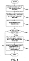
- the straightening method of a crankpin 101 shown for example, for the crankshaft 100 is shown in FIG. 5 as a flowchart.
- the method shown in FIG. 5 applies for the straightening of a crankpin 101, but is also applicable to the straightening of the journal 103 as presented earlier, and also for the straightening of a feature on any eccentric shaft, like for example the straightening of a lobe or a journal feature on a camshaft.
- the crankshaft 100 is mounted by targets 107 and 111 for rotation in the deep rolling machine 300 in step 901 of FIG. 5 .
- the crankshaft 100 is rotated in the deep rolling machine 300 in step 903.
- Appropriate sensors sense the rotational position and alignment of the crankpin 101 during the rotation of the crankshaft 100 to record the angular position thereof relative to a known crankshaft reference position, such as a plane established between TDC and BDC of the pin 101, as well as deflection in step 905.
- each roller 303 makes contact with its respective groove 201 on either side of a crankpin 101 and the rollers 308 engage the body portion 309 of the crankpin 101 in step 909.
- the deep rolling machine 300 may be capable of engaging a single crankpin 101 or a single main journal 103, or a plurality of them simultaneously.
- rollers 308 have fixed axes to provide passive resistance to the compressive forces 301 generated by the rollers 303 but alternatively may be actively loaded by the structures 307. Once the rollers 303 are engaged in their respective grooves 201 and the rollers 308 engaged on the body surface, a compressive force 301 is imparted through each roller 303 and/or 308 as described above. This compressive force 301 makes adjustments to the straightness of the crankshaft 100 in step 911.
- Fig. 6 illustrates the application of the compressive force 301 when the plane of maximum run-out corresponds to an angle 605 relative to an initial mounting rotational position of the crankshaft 100. Each application of the compressive force 301 occurs once for a full revolution of the crankshaft 100.
- each rotation of the crankshaft 100 is shown with respect to a specific crankpin 100 engaged by the deep rolling machine 300.
- the duration of application of the compressive force 301 is shown as ramping up before the angle 605 , reaching a maximum value at the angle 605 , and ramping back down after the angle 605 to a low nominal value at least sufficient to maintain the engagement of the rollers 303, 308 that could be zero.
- a computer connected to sensors makes a determination on whether the crankshaft 100 is in a state of acceptable straightness. If the crankshaft 100 straightness is still not acceptable, an additional application of the compressive force 301 is required, which can have an equal, lesser or greater magnitude than the first application.
- crankshaft 100 has attained a desired straightness for the crankpin 101 that is engaged.
- the magnitude of the compressive force 301 depends on the amount of deflection that is being corrected, and may advantageously be between about 6 to 17 kN.
- the deep rolling machine 300 then disengages the crankpin 101 and proceeds to engage an adjacent crankpin 101 as described earlier.
- the straightening process may be repeated on the adjacent crankpin 101.
- all of the crankpins may be engaged and straightened sequentially as the crankshaft rotates.
- a similar process may be applied to the main journals. After each crankpin 101 and/or main journal has been subjected to the straightening process, the crankshaft 100 should be acceptably straight.
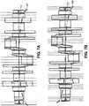
- crankshafts can be found in many different forms. As is shown in FIG. 7A and FIG. 7B , a crankshaft can have a bowed centerline 417 or an S-shaped centerline 415. These are two examples of the at least 10 different families of distortions that have been observed in crankshafts thus far, whose centerlines may deviate three-dimensionally from a desired straight centerline 113. This invention is advantageously suitable to manage any deflection of the centerline 113 of a crankshaft 100, because it is able to align each crankpin 101 or main journal 103 independently of the rest.
- crankshafts having a martensitic crystalline structure without compromising its strength, and the ability to perform a straightening operation quickly and using common equipment in the art of manufacturing crankshafts are additional advantages.
- This embodiment involves operations made to crankshafts designed for use in internal combustion engines. This method, however, would work equally well for crankshafts, camshafts or any eccentric shaft designed for any other application or machine.
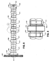
- a typical camshaft 501 is shown in FIG. 8 .
- This camshaft 501 is configured for use in a V-8 internal combustion engine, preferably a diesel engine, but the advantages of this invention can be realized when used not only on a camshaft resembling the one shown, but any camshaft used on any engine or machine.
- a camshaft 501 typically may include at one end, a cylindrical front seal surface 503 to engage a conventional front seal (not shown) disposed on a front side of an engine.
- a rear seal surface 505 similarly provides engagement of a conventional rear crankshaft seal (not shown) and a rear driving gear 507 disposed on a rear side of the engine.
- the camshaft 501 may have one or more main journals 509 which engage in a conventional manner bearings (not shown) in the engine (not shown) to support the camshaft 501, and a plurality of lobes 511 that are engaged by conventional cam followers (not shown) or valve lifters (not shown) to actuate intake and exhaust valves for the cylinders.
- a camshaft 501 for a V8 engine as shown, sixteen lobes 511 are separated by the journals 509 in sets of four.
- the camshaft 501 further has a front target 513 and a rear target 515 identifying the centers of the front journal 503 and the rear journal 505 respectively, defining an imaginary centerline 517 through the camshaft 501, and providing points of engagement with a deep rolling machine.
- the camshaft centerline 517 is a straight line coinciding with the axis of rotation extending between the front target 513 and rear target 515.
- FIG. 9 A detailed view of the intersection between two adjacent sets of lobes 511 around one journal 509 is shown in FIG. 9 .
- a continuous peripheral groove or fillet 601 can be seen on either side of the journal 509 forming a smooth radius blending into the main shaft 603. Similar fillets are found on either side of each journal 509.
- the area of each of the fillets 601 is a stress concentration area on the camshaft 501 during operation.
- Each fillet 601 is intended to alleviate the stresses going through it during engine operation.
- These fillets are manufactured to provide residual compressive stresses in the steel in these areas. The compressive stresses in the fillets help offset tensile stresses that occur during operation.
- camshafts that undergo a hardening process may develop problems with the straightness of their centerlines.
- This invention presents a method to straighten the centerline 517 of a camshaft 501, without compromising the residual compressive stresses provided in each fillet 601, after the camshaft 501 has undergone a hardening process.
- a deep rolling machine 300 may be used to hold and rotate the camshaft 501 about the rotational axis 517 between the targets 513 and 515.
- An appropriate journal structure 701 with rollers 703 running on each fillet 601 may be provided to follow each journal 509 without losing contact between the rollers 703 and the fillets 601.
- an appropriate support structure 705 with rollers 707 may be provided to run on the body of the journal 509 without losing contact between the rollers 707 and the body of the journal 509.
- a compressive force 709 would cause the camshaft 501 to straighten in the section clamped by the machine 300, in this case, the journal 509 shown in FIG. 10B by acting through the rollers 709 on the grooves 601 during a predetermined circumferential segment substantially at, or ramping up or down from, a rotational position of the camshaft 501 corresponding to a plane of maximum run-out while the rollers 707 are arranged to resist and divide the radial component of the compressive force 709 as shown in FIG. 10C .
- each compressive force 709 the section of the camshaft 501 that includes the journal 509 between the rollers 703, 707 may be straightened by causing plastic deformation or flow of solid material around each fillet 601 by the action of the axial components of each compressive force 709. These compressive forces do not put the material of the camshaft 501 into tension, and thus, do not lessen its strength.
- Each compressive force 301, 709 is equal in magnitude in a radial force balance direction.
- the application of each compressive force 301, 709 may occur in any desired scheme that is a function of angle of rotation of the crankshaft 100 or the camshaft 501 mounted in the deep rolling machine 300, or a function of timing with respect to the rotational speed of the crankshaft 100 or the camshaft 501 mounted in the deep rolling machine 300.
- Angular sensors, visual sensors, rotational position sensors, stress sensors, positional sensors, timing sensors, and so forth can sense the angular position or the rotational speed of the crankshaft 100 or the camshaft 501 as mounted in the machine 300 during operation.
Landscapes
- Engineering & Computer Science (AREA)
- Mechanical Engineering (AREA)
- Shafts, Cranks, Connecting Bars, And Related Bearings (AREA)
- Finish Polishing, Edge Sharpening, And Grinding By Specific Grinding Devices (AREA)
- Golf Clubs (AREA)
- Mechanical Treatment Of Semiconductor (AREA)
- Forging (AREA)
- Heat Treatment Of Articles (AREA)
Applications Claiming Priority (2)
| Application Number | Priority Date | Filing Date | Title |
|---|---|---|---|
| US11/100,701 US7188497B2 (en) | 2005-04-07 | 2005-04-07 | Method for straightening an eccentric shaft |
| PCT/US2006/011145 WO2006110312A2 (en) | 2005-04-07 | 2006-03-27 | Method for straightening an eccentric shaft |
Publications (3)
| Publication Number | Publication Date |
|---|---|
| EP1868750A2 EP1868750A2 (en) | 2007-12-26 |
| EP1868750A4 EP1868750A4 (en) | 2009-04-08 |
| EP1868750B1 true EP1868750B1 (en) | 2012-04-25 |
Family
ID=37081849
Family Applications (1)
| Application Number | Title | Priority Date | Filing Date |
|---|---|---|---|
| EP06739752A Not-in-force EP1868750B1 (en) | 2005-04-07 | 2006-03-27 | Method for straightening an eccentric shaft |
Country Status (9)
| Country | Link |
|---|---|
| US (1) | US7188497B2 (enExample) |
| EP (1) | EP1868750B1 (enExample) |
| JP (1) | JP5271698B2 (enExample) |
| KR (1) | KR20080003869A (enExample) |
| CN (1) | CN101180142B (enExample) |
| AT (1) | ATE554865T1 (enExample) |
| BR (1) | BRPI0607023B1 (enExample) |
| CA (1) | CA2603996C (enExample) |
| WO (1) | WO2006110312A2 (enExample) |
Families Citing this family (12)
| Publication number | Priority date | Publication date | Assignee | Title |
|---|---|---|---|---|
| DE102010056616A1 (de) * | 2010-12-23 | 2012-06-28 | Hegenscheidt-Mfd Gmbh & Co. Kg | Verfahren zum Richtwalzen von Kurbelwellen |
| CN103447357B (zh) * | 2013-08-30 | 2015-07-29 | 神华集团有限责任公司 | 搅拌器轴的校直方法 |
| CN104438479A (zh) * | 2014-10-28 | 2015-03-25 | 南车戚墅堰机车有限公司 | 机车曲轴变形校调方法 |
| CN104646457A (zh) * | 2015-01-16 | 2015-05-27 | 滨州海得曲轴有限责任公司 | 一种曲轴轴颈直线度矫正方法 |
| US10227937B2 (en) | 2015-11-04 | 2019-03-12 | Ge Global Sourcing Llc | Methods and system for a turbocharger |
| CN108620452B (zh) * | 2017-03-22 | 2020-05-12 | 沈阳铸造研究所 | 一种钛合金异型管状铸件的热矫形方法 |
| DE102017113071A1 (de) * | 2017-06-14 | 2018-12-20 | Maschinenfabrik Alfing Kessler Gmbh | Verfahren und Vorrichtung zur Nachbearbeitung einer Kurbelwelle |
| CN107695138B (zh) * | 2017-09-20 | 2019-04-30 | 上海理工大学 | 一种曲轴扭转变形的矫正装置和方法 |
| CN110871341A (zh) * | 2018-08-31 | 2020-03-10 | 蒂森克虏伯发动机系统(大连)有限公司 | 制造带齿凸轮轴的方法 |
| JP7305567B2 (ja) * | 2020-01-22 | 2023-07-10 | 株式会社東芝 | 接合形タービンロータの曲がり修正方法 |
| CN111649705B (zh) * | 2020-06-30 | 2024-08-13 | 中国计量科学研究院 | 一种用于凸轮轴测量仪校准的偏心轴及其校准方法 |
| CN116618479B (zh) * | 2023-07-19 | 2023-09-22 | 常州三协电机股份有限公司 | 一种丝杆校直装置 |
Family Cites Families (20)
| Publication number | Priority date | Publication date | Assignee | Title |
|---|---|---|---|---|
| DE2346796A1 (de) * | 1973-09-17 | 1975-04-03 | Eitel Kg Werzeugmaschinenfabri | Automatisches richtverfahren und richtmaschine dafuer mit mehreren richtstellen |
| SU730550A1 (ru) * | 1977-07-13 | 1980-04-30 | Научно-Производственное Объединение По Технологии Машиностроения "Цниитмаш" | Способ упрочн ющей обработки коленчатых валов |
| JPS59101228A (ja) * | 1982-11-30 | 1984-06-11 | Hino Motors Ltd | クランクシヤフトの曲り矯正法と装置 |
| DE3701223A1 (de) * | 1987-01-17 | 1988-07-28 | Augustin Hans Georg | Verfahren und vorrichtung zum richten eines werkstuecks |
| DE3789961D1 (de) | 1987-07-13 | 1994-07-07 | Hegenscheidt Gmbh Wilhelm | Verfahren und Einrichtung zum Richten von Schlag aufweisenden Werkstücken. |
| US5235838A (en) | 1987-07-13 | 1993-08-17 | W. Hegenscheidt Gesellschaft Mbh | Method and apparatus for truing or straightening out of true work pieces |
| DE59004629D1 (de) | 1990-06-15 | 1994-03-24 | Hegenscheidt Gmbh Wilhelm | Verfahren zum Glatt- bzw Festwalzen von mehrhübigen Kurbelwellen und Maschine zur Durchführung des Verfahrens. |
| US5495738A (en) | 1994-05-13 | 1996-03-05 | Hegenscheidt Corporation | Metal rolling machine with opposing banks of jaw units for working a centered workpiece and method of rolling annular fillets of workpieces |
| US5445003A (en) | 1994-01-03 | 1995-08-29 | Hegenscheidt Corporation | Engine crank pin rolling equipment, rolling tool and method of rolling adjacent and offset crank pins |
| US5575167A (en) * | 1994-01-03 | 1996-11-19 | Hegenscheidt Corporation | Deep rolling split-pin fillets of crankshafts |
| US5493761A (en) | 1994-10-24 | 1996-02-27 | Ingersoll Cm Systems, Inc. | Apparatus for fillet rolling of crankshafts |
| JP3593753B2 (ja) * | 1995-08-04 | 2004-11-24 | 日産自動車株式会社 | フィレットローリング加工装置およびこの装置における傷判定方法 |
| WO1998051432A1 (en) | 1997-05-16 | 1998-11-19 | Hegenscheidt-Mfd Corporation | Support tool for deep rolling crankshaft fillets |
| DE19722308C1 (de) * | 1997-05-28 | 1998-04-16 | Hegenscheidt Mfd Gmbh | Festwalzmaschine für Kurbelwellen |
| JP3634961B2 (ja) * | 1998-05-22 | 2005-03-30 | 株式会社神戸製鋼所 | クランク軸の曲がり矯正方法 |
| FR2790691B1 (fr) * | 1999-03-09 | 2001-04-27 | Process Conception Ing Sa | Perfectionnements aux machines de galetage, notamment pour le vilebrequin d'un moteur de vehicule automobile |
| DE10052753A1 (de) | 2000-10-25 | 2002-05-08 | Hegenscheidt Mfd Gmbh & Co Kg | Gerät zum Festwalzen von Kurbelwellen |
| US6393885B1 (en) | 2000-11-07 | 2002-05-28 | Hegenscheidt Mfd Corporation | Tooling for deep rolling fillets of crankshaft journals |
| ATE499162T1 (de) | 2000-11-22 | 2011-03-15 | Ingersoll Cm Systems Inc | Vorrichtung und verfahren für das walzen von werkstücken |
| ATE308405T1 (de) | 2001-05-28 | 2005-11-15 | Hegenscheidt Mfd Gmbh & Co Kg | Vorrichtung zum festwalzen von einstichen und radien der lagerstellen von kurbelwellen |
-
2005
- 2005-04-07 US US11/100,701 patent/US7188497B2/en not_active Expired - Lifetime
-
2006
- 2006-03-27 KR KR1020077025825A patent/KR20080003869A/ko not_active Ceased
- 2006-03-27 BR BRPI0607023-0A patent/BRPI0607023B1/pt active IP Right Grant
- 2006-03-27 CA CA2603996A patent/CA2603996C/en not_active Expired - Fee Related
- 2006-03-27 AT AT06739752T patent/ATE554865T1/de active
- 2006-03-27 CN CN2006800177791A patent/CN101180142B/zh active Active
- 2006-03-27 JP JP2008505363A patent/JP5271698B2/ja not_active Expired - Fee Related
- 2006-03-27 WO PCT/US2006/011145 patent/WO2006110312A2/en not_active Ceased
- 2006-03-27 EP EP06739752A patent/EP1868750B1/en not_active Not-in-force
Also Published As
| Publication number | Publication date |
|---|---|
| CN101180142B (zh) | 2010-09-29 |
| KR20080003869A (ko) | 2008-01-08 |
| CA2603996C (en) | 2012-01-10 |
| WO2006110312A3 (en) | 2007-08-30 |
| US20060225478A1 (en) | 2006-10-12 |
| ATE554865T1 (de) | 2012-05-15 |
| WO2006110312A2 (en) | 2006-10-19 |
| US7188497B2 (en) | 2007-03-13 |
| BRPI0607023B1 (pt) | 2020-11-03 |
| EP1868750A4 (en) | 2009-04-08 |
| CN101180142A (zh) | 2008-05-14 |
| JP5271698B2 (ja) | 2013-08-21 |
| CA2603996A1 (en) | 2006-10-19 |
| BRPI0607023A2 (pt) | 2009-08-04 |
| JP2008535665A (ja) | 2008-09-04 |
| EP1868750A2 (en) | 2007-12-26 |
Similar Documents
| Publication | Publication Date | Title |
|---|---|---|
| EP1868750B1 (en) | Method for straightening an eccentric shaft | |
| KR101310772B1 (ko) | 왕복 피스톤 엔진용 기어휠 및 밸런스 샤프트 | |
| US4569109A (en) | Method of making a split bearing assembly | |
| US4684267A (en) | Split bearing assemblies | |
| US7036468B2 (en) | Internal combustion engine with variable compression ratio and compression ratio control method | |
| EP1382866B1 (en) | Connecting rod with a split rod-eye | |
| US20090257702A1 (en) | Shaft with roller bearing | |
| US20140260787A1 (en) | Selectively strengthened crankshaft | |
| US20100107808A1 (en) | Method for increasing torsional fatigue strength in crankshafts | |
| US4015485A (en) | Crank shaft for a multi-cylinder short stroke internal combustion engine | |
| JP2613079B2 (ja) | クランクシャフトの製造方法 | |
| JP2006247727A (ja) | クランクシャフトにおけるカウンタウエイトの形状矯正方法 | |
| Blanchard et al. | Assembled camshaft with sintered cam lobes: torsional fatigue strength and wear performance | |
| JPS5969516A (ja) | クランクシヤフト | |
| JP6037017B2 (ja) | 組立カムシャフト | |
| CN112639306A (zh) | 曲轴 | |
| JP3368802B2 (ja) | 組立式カムシャフト | |
| US10794270B2 (en) | Connecting rod for an internal combustion engine with variable compression | |
| JP3037925B2 (ja) | 一体式中空プッシュロッドの製造方法 | |
| JP2011043208A (ja) | クランクシャフト | |
| JP6102407B2 (ja) | カムの製造方法 | |
| JP6241367B2 (ja) | 複リンク式ピストンクランク機構におけるリンク連結構造およびリンク連結方法 | |
| Kavuri et al. | Fracture, Fatigue Growth Rate And Vibration Analysis Of Camshaft In Railways | |
| JP2007247528A (ja) | 内燃機関の可変圧縮比機構 |
Legal Events
| Date | Code | Title | Description |
|---|---|---|---|
| PUAI | Public reference made under article 153(3) epc to a published international application that has entered the european phase |
Free format text: ORIGINAL CODE: 0009012 |
|
| 17P | Request for examination filed |
Effective date: 20071018 |
|
| AK | Designated contracting states |
Kind code of ref document: A2 Designated state(s): AT BE BG CH CY CZ DE DK EE ES FI FR GB GR HU IE IS IT LI LT LU LV MC NL PL PT RO SE SI SK TR |
|
| AX | Request for extension of the european patent |
Extension state: AL BA HR MK YU |
|
| RIC1 | Information provided on ipc code assigned before grant |
Ipc: B23P 17/00 20060101ALI20080124BHEP Ipc: B21K 1/08 20060101ALI20080124BHEP Ipc: B21D 37/16 20060101ALI20080124BHEP Ipc: B21D 15/00 20060101ALI20080124BHEP Ipc: B21C 51/00 20060101ALI20080124BHEP Ipc: B21B 37/00 20060101ALI20080124BHEP Ipc: B21B 37/24 20060101AFI20080124BHEP |
|
| DAX | Request for extension of the european patent (deleted) | ||
| RBV | Designated contracting states (corrected) |
Designated state(s): AT DE FR GB IT SE |
|
| RBV | Designated contracting states (corrected) |
Designated state(s): AT DE FR GB IT SE |
|
| A4 | Supplementary search report drawn up and despatched |
Effective date: 20090306 |
|
| 17Q | First examination report despatched |
Effective date: 20091006 |
|
| GRAP | Despatch of communication of intention to grant a patent |
Free format text: ORIGINAL CODE: EPIDOSNIGR1 |
|
| GRAS | Grant fee paid |
Free format text: ORIGINAL CODE: EPIDOSNIGR3 |
|
| GRAA | (expected) grant |
Free format text: ORIGINAL CODE: 0009210 |
|
| AK | Designated contracting states |
Kind code of ref document: B1 Designated state(s): AT DE FR GB IT SE |
|
| REG | Reference to a national code |
Ref country code: GB Ref legal event code: FG4D |
|
| REG | Reference to a national code |
Ref country code: AT Ref legal event code: REF Ref document number: 554865 Country of ref document: AT Kind code of ref document: T Effective date: 20120515 |
|
| REG | Reference to a national code |
Ref country code: DE Ref legal event code: R096 Ref document number: 602006029080 Country of ref document: DE Effective date: 20120621 |
|
| REG | Reference to a national code |
Ref country code: AT Ref legal event code: MK05 Ref document number: 554865 Country of ref document: AT Kind code of ref document: T Effective date: 20120425 |
|
| PG25 | Lapsed in a contracting state [announced via postgrant information from national office to epo] |
Ref country code: SE Free format text: LAPSE BECAUSE OF FAILURE TO SUBMIT A TRANSLATION OF THE DESCRIPTION OR TO PAY THE FEE WITHIN THE PRESCRIBED TIME-LIMIT Effective date: 20120425 |
|
| PG25 | Lapsed in a contracting state [announced via postgrant information from national office to epo] |
Ref country code: AT Free format text: LAPSE BECAUSE OF FAILURE TO SUBMIT A TRANSLATION OF THE DESCRIPTION OR TO PAY THE FEE WITHIN THE PRESCRIBED TIME-LIMIT Effective date: 20120425 |
|
| PG25 | Lapsed in a contracting state [announced via postgrant information from national office to epo] |
Ref country code: IT Free format text: LAPSE BECAUSE OF FAILURE TO SUBMIT A TRANSLATION OF THE DESCRIPTION OR TO PAY THE FEE WITHIN THE PRESCRIBED TIME-LIMIT Effective date: 20120425 |
|
| PLBE | No opposition filed within time limit |
Free format text: ORIGINAL CODE: 0009261 |
|
| STAA | Information on the status of an ep patent application or granted ep patent |
Free format text: STATUS: NO OPPOSITION FILED WITHIN TIME LIMIT |
|
| 26N | No opposition filed |
Effective date: 20130128 |
|
| PGFP | Annual fee paid to national office [announced via postgrant information from national office to epo] |
Ref country code: FR Payment date: 20130315 Year of fee payment: 8 |
|
| REG | Reference to a national code |
Ref country code: DE Ref legal event code: R097 Ref document number: 602006029080 Country of ref document: DE Effective date: 20130128 |
|
| PGFP | Annual fee paid to national office [announced via postgrant information from national office to epo] |
Ref country code: DE Payment date: 20130328 Year of fee payment: 8 |
|
| GBPC | Gb: european patent ceased through non-payment of renewal fee |
Effective date: 20130327 |
|
| PG25 | Lapsed in a contracting state [announced via postgrant information from national office to epo] |
Ref country code: GB Free format text: LAPSE BECAUSE OF NON-PAYMENT OF DUE FEES Effective date: 20130327 |
|
| REG | Reference to a national code |
Ref country code: DE Ref legal event code: R119 Ref document number: 602006029080 Country of ref document: DE |
|
| REG | Reference to a national code |
Ref country code: FR Ref legal event code: ST Effective date: 20141128 |
|
| PG25 | Lapsed in a contracting state [announced via postgrant information from national office to epo] |
Ref country code: FR Free format text: LAPSE BECAUSE OF NON-PAYMENT OF DUE FEES Effective date: 20140331 Ref country code: DE Free format text: LAPSE BECAUSE OF NON-PAYMENT OF DUE FEES Effective date: 20141001 |
|
| REG | Reference to a national code |
Ref country code: DE Ref legal event code: R119 Ref document number: 602006029080 Country of ref document: DE Effective date: 20141001 |