EP1865587A2 - Magnetkern bestehend aus magnetischem Metallpulver für elektrische Maschinen - Google Patents
Magnetkern bestehend aus magnetischem Metallpulver für elektrische Maschinen Download PDFInfo
- Publication number
- EP1865587A2 EP1865587A2 EP07252001A EP07252001A EP1865587A2 EP 1865587 A2 EP1865587 A2 EP 1865587A2 EP 07252001 A EP07252001 A EP 07252001A EP 07252001 A EP07252001 A EP 07252001A EP 1865587 A2 EP1865587 A2 EP 1865587A2
- Authority
- EP
- European Patent Office
- Prior art keywords
- edge
- core segment
- section
- assembly
- top section
- Prior art date
- Legal status (The legal status is an assumption and is not a legal conclusion. Google has not performed a legal analysis and makes no representation as to the accuracy of the status listed.)
- Granted
Links
Images

Classifications
-
- H—ELECTRICITY
- H01—ELECTRIC ELEMENTS
- H01F—MAGNETS; INDUCTANCES; TRANSFORMERS; SELECTION OF MATERIALS FOR THEIR MAGNETIC PROPERTIES
- H01F3/00—Cores, Yokes, or armatures
- H01F3/08—Cores, Yokes, or armatures made from powder
-
- H—ELECTRICITY
- H02—GENERATION; CONVERSION OR DISTRIBUTION OF ELECTRIC POWER
- H02K—DYNAMO-ELECTRIC MACHINES
- H02K1/00—Details of the magnetic circuit
- H02K1/06—Details of the magnetic circuit characterised by the shape, form or construction
- H02K1/12—Stationary parts of the magnetic circuit
- H02K1/14—Stator cores with salient poles
- H02K1/146—Stator cores with salient poles consisting of a generally annular yoke with salient poles
- H02K1/148—Sectional cores
-
- H—ELECTRICITY
- H02—GENERATION; CONVERSION OR DISTRIBUTION OF ELECTRIC POWER
- H02K—DYNAMO-ELECTRIC MACHINES
- H02K1/00—Details of the magnetic circuit
- H02K1/06—Details of the magnetic circuit characterised by the shape, form or construction
- H02K1/22—Rotating parts of the magnetic circuit
- H02K1/24—Rotor cores with salient poles ; Variable reluctance rotors
-
- H—ELECTRICITY
- H02—GENERATION; CONVERSION OR DISTRIBUTION OF ELECTRIC POWER
- H02K—DYNAMO-ELECTRIC MACHINES
- H02K1/00—Details of the magnetic circuit
- H02K1/02—Details of the magnetic circuit characterised by the magnetic material
-
- H—ELECTRICITY
- H02—GENERATION; CONVERSION OR DISTRIBUTION OF ELECTRIC POWER
- H02K—DYNAMO-ELECTRIC MACHINES
- H02K2201/00—Specific aspects not provided for in the other groups of this subclass relating to the magnetic circuits
- H02K2201/06—Magnetic cores, or permanent magnets characterised by their skew
-
- Y—GENERAL TAGGING OF NEW TECHNOLOGICAL DEVELOPMENTS; GENERAL TAGGING OF CROSS-SECTIONAL TECHNOLOGIES SPANNING OVER SEVERAL SECTIONS OF THE IPC; TECHNICAL SUBJECTS COVERED BY FORMER USPC CROSS-REFERENCE ART COLLECTIONS [XRACs] AND DIGESTS
- Y10—TECHNICAL SUBJECTS COVERED BY FORMER USPC
- Y10T—TECHNICAL SUBJECTS COVERED BY FORMER US CLASSIFICATION
- Y10T29/00—Metal working
- Y10T29/49—Method of mechanical manufacture
- Y10T29/49002—Electrical device making
- Y10T29/49009—Dynamoelectric machine
Definitions
- the present invention relates to core components for use in electrical machines and, more particularly, a component assembly for use in an electrical machine, most typically an electric motor.
- stator stationary element
- rotor movable or rotating elements
- the interaction between the stator and the rotor is caused by the interaction of a magnetic field generated by either the stator or the rotor.
- Such magnetic field is usually generated or induced by electric currents in a winding placed on either the stator or the rotor.
- Such winding usually comprises a plurality of coils wound about a winding support.
- the winding support is usually comprised of a soft magnetic material which traditionally is made of laminations of selected steel materials. The laminations are insulated from each other in order to reduce eddy currents.
- the core segments have skewed ends. Accordingly, the cogging torque of the motor itself is reduced.
- the present invention provides an improved component assembly for an electrical machine and, more specifically, an improved stator or rotor assembly for use in an electrical motor or generator.
- the improved component assembly comprises a top section and a bottom section.
- Each top section is comprised of a generally cylindrical center portion, a plurality of winding supports extending radially outward from the center portion, and a core segment at a radial edge of each winding support.
- Each bottom section is comprised of a generally cylindrical center portion, a plurality of winding supports extending radially outward from the center portion, and a core segment in a radial edge of each winding segment support.
- the top section and the bottom section are combined to form the component assembly.
- each of the top section and the bottom section are formed of ferrous magnetic powder particles.
- ferrous magnetic powder particles are mutually insulated.
- the ferrous magnetic metal powder particles are pressure formed in a powder metal operation into a solid form.
- such an improved component assembly comprised of a combined top section and bottom section with skewed core segments formed of mutually insulated ferrous magnetic powder metal particles provides improved performance in the electrical machine.
- Such improved performance is mainly due to the skewed core segments which reduce the cogging torque of the electrical machine and the use of the mutually insulated ferrous magnetic powder metal particles to form the top section and the bottom section which also reduces eddy current losses.
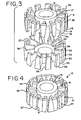
- a component for use in an electrical machine is shown generally at 10.
- Such component 10 can be a stator or a rotor for use most typically in a motor, but component 10 could also be used in a generator.
- Component 10 is seen to be comprised of a top section 9 and having a center portion 12.
- Center portion 12 is usually cylindrical in shape with a central open section.
- Center portion 12 includes a radial center axis 13.
- a plurality of winding supports 17 extend radially outward from center portion 12 outer surface. The number of each such winding supports can vary based on the size and design of component 10, but the number is usually between eight and twenty-four.
- Each winding support 17 is generally rectangular in shape, having a top edge and a bottom edge that are parallel and an inside edge adjacent center portion 12 outer surface.
- Each winding support 17 also has an outer edge.
- Each outer edge of each winding support 17 has a top section core segment 14 affixed thereto or protruding therefrom.
- Each top section core segment 14 has a top edge 40, and a bottom edge 42; top edge 40 and bottom edge 42 are usually parallel.
- Each top section core segment 14 also includes a first side edge 44 and a second side edge 46.
- First side edge 44 is usually parallel with radial center axis 13.
- Second side edge 46 is usually skewed at an acute angle to radial center axis 13; such outer angle is usually between five and thirty degrees.
- Center portion 12 of top section 9 is generally cylindrical with a centered open section and a radial center axis 13. Center portion 12 has a generally flat bottom surface 26.
- Each top section core segment 14 has an outer surface 16 that is convex about top section radial axis 13.
- the convex nature of the top section core segment 14 outer surface 16 is designed to form a generally cylindrical form outer edge of top section 9.
- Component 10 is seen to be also comprised of a bottom section 29 having a center portion 20.
- Center portion 20 is usually cylindrical in shape with a central open section.
- Center portion 20 includes a radial center axis 13 when top section 9 is combined with bottom section 29.
- a plurality of winding supports 27 extend radially outward from center portion 20 outer surface. The number of such winding supports can vary based on the size and design or component 10, but the number is usually between eight and twenty-four.
- Each winding support 27 is generally rectangular in shape, having a top edge and a bottom edge that are parallel and an inside edge adjacent center portion 20 outer surface.
- Each winding support 27 also has an outer edge.
- Each outer edge of each winding support 27 has a bottom section core segment 22 affixed thereto or protruding therefrom.
- Each bottom section core segment 22 has a top edge 50 and a bottom edge 52; top edge 50 and bottom edge 52 are usually parallel.
- Each bottom section core segment 22 also includes a first side edge 54 and a second side edge 56.
- First side edge 54 is usually parallel with radial center axis 13.
- Second side edge 56 is usually skewed at an acute angle to radial center axis 13; such outer angle is usually between five and thirty degrees.
- Center portion 20 of bottom section 29 is generally cylindrical with a central open section and a radial center axis 13. Center portion 20 has a generally flat top surface 24.
- Each bottom section core segment 22 has an outer surface 30 that is convex about bottom section radial axis 13.
- the convex nature of bottom section core segment 22 outer surface 30 is designed to form a generally cylindrical form outer edge of bottom section 29.
- top section 9 When top section 9 is fitted on top of bottom section 29, a complete component 10 is formed.
- the bottom surface 26 of top section center portion 12 is seen to fit against top surface 24 of bottom section center portion 20.
- Each winding support 17 of top section 9 is seen to fit adjacent a winding support 27 of bottom section 29.
- a generally rectangular combined winding support is formed to receive winding 18.
- Winding 18 is a typical winding of an insulated electrical wire that provides the magnetic field for the electrical machine.
- Each top section core segment 14 is seen to combine with an adjacent bottom section core segment 22 to form a combined skewed core segment 25 in the assembled component 10.
- each top section core segment 14 is seen to be placed adjacent side edge 54 of each bottom section core segment 22.
- combined skewed core segment 25 is formed.
- Combined skewed core segment 25 is seen to have a top edge 35 and a bottom edge 37 that are usually parallel.
- Combined skewed core segment 25 is also seen to have a first side edge 39 and a second side edge 41 that are also usually parallel, but at an acute angle of from five to thirty degrees from the top edge 35.
- each combined skewed core segment 25 is usually a parallelogram; further, each combined skewed core segment 25 is spaced to be electrically insulated from adjacent combined skewed core segments.
- Such combined core segments 25 where utilized as stators or rotors in electrical machines such as motors tend to reduce the cogging torque of the electrical motor.
- top section 9 and bottom section 29 are usually unitary structures comprised of a compacted ferrous magnetic powder.
- the compacted ferrous magnetic powder itself is comprised of insulated ferrous powder particles.
- the ferrous magnetic powder is die compacted in a powder metal operation. Some subsequent heat treatment to produce stress relieved components may be performed. Such heat treatment also aids in providing a compound with high magnetic permeability and low core loss.
- the ferrous magnetic powder particles used are insulated electrically from each other to diminish the build up of eddy currents within the assembled component 10.
- top section 9 is shown with its previously described components.
- ferrous powder metal die compaction techniques it is quite difficult to form a skewed edge such as second side edge 46.
- the difficulty arises from the compaction of a skewed edge to the direction of the die compaction and the difficulty of die compaction and the difficulty in removing the compacted part having a skewed edge from the die.
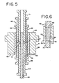
- the method of the present invention accomplishes the die compaction of the top section 9, and also bottom section 29, using, in one embodiment, the die arrangement shown in Figs. 5 and 6.
- Die 68 is shown as being somewhat cylindrical in over all shape, given the cross sectional view of Fig. 5.
- Die 68 has an outer edge 67, top edge 65, bottom edge 63 and inner edge 61.
- Inner edge 61 of die 68 abuts inner die section 69.
- Inner die section 69 has a generally cylindrical opening centrally located therein.
- Inner die section 69 has shelf edges that form first side edge 44 and second side edge 46 of top section 9.
- First upper fill punch 62 is adjacent the inner edge of infer die section 69.
- Second upper fill punch 60 is adjacent the inner edge of first upper fill punch 62.
- Third upper fill punch 71 is adjacent the inner edge of second upper fill punch 60.
- first lower fill punch 70 is adjacent the inner edge of inner die section 69.
- Second lower fill punch 66 is adjacent the inner edge of first lower fill punch 70.
- Third lower fill punch 64 is adjacent the inner edge of second lower fill punch 66.
- Al fill punches mentioned above are generally cylindrical in shape given the generally cylindrical shape of top section 9 and die 68.
- a core rod 65 extends along what will be the radial center axis 13 of top section 9. Core rod 65 is adjacent the inner edges of third upper fill punch 71 and third lower fill punch 64.
- the opening corresponding to what will become top section 9 is filled with the appropriate ferrous magnetic powder.
- the die compaction is accomplished using, in one embodiment, the die arrangement described above.
- the ferrous magnetic powder used to form top section 9 and bottom section 29 is usually a high purity soft magnetic iron powder.
- the ferrous powder particles are coated with an organic, inorganic, or a combination insulating coating.
- top section 9 and bottom section 29 may be bonded to each other using a bonding adhesive or an epoxy. It is also possible for the top section 9 to be held together to bottom section 29 sufficiently, depending on component design, by the windings 18.
Landscapes
- Engineering & Computer Science (AREA)
- Power Engineering (AREA)
- Iron Core Of Rotating Electric Machines (AREA)
- Manufacture Of Motors, Generators (AREA)
Applications Claiming Priority (1)
| Application Number | Priority Date | Filing Date | Title |
|---|---|---|---|
| US11/446,260 US7538467B2 (en) | 2006-06-05 | 2006-06-05 | Magnetic powder metal composite core for electrical machines |
Publications (3)
| Publication Number | Publication Date |
|---|---|
| EP1865587A2 true EP1865587A2 (de) | 2007-12-12 |
| EP1865587A3 EP1865587A3 (de) | 2011-05-11 |
| EP1865587B1 EP1865587B1 (de) | 2018-10-10 |
Family
ID=38543945
Family Applications (1)
| Application Number | Title | Priority Date | Filing Date |
|---|---|---|---|
| EP07252001.8A Active EP1865587B1 (de) | 2006-06-05 | 2007-05-16 | Magnetkern bestehend aus magnetischem Metallpulver für elektrische Maschinen |
Country Status (8)
| Country | Link |
|---|---|
| US (2) | US7538467B2 (de) |
| EP (1) | EP1865587B1 (de) |
| JP (1) | JP4489096B2 (de) |
| KR (1) | KR100885763B1 (de) |
| CN (1) | CN101098087B (de) |
| EA (1) | EA011006B1 (de) |
| ES (1) | ES2693611T3 (de) |
| TW (1) | TWI355129B (de) |
Cited By (2)
| Publication number | Priority date | Publication date | Assignee | Title |
|---|---|---|---|---|
| US20200350798A1 (en) * | 2018-01-17 | 2020-11-05 | Genesis Robotics And Motion Technologies Vanada Ukc | Actuator stator |
| EP3920375A1 (de) * | 2017-05-31 | 2021-12-08 | Genesis Robotics and Motion Technologies Canada, ULC | Einsätze für träger für elektrische maschinen |
Families Citing this family (13)
| Publication number | Priority date | Publication date | Assignee | Title |
|---|---|---|---|---|
| WO2008100043A1 (en) * | 2007-02-16 | 2008-08-21 | Samsung Electronics Co., Ltd. | Active reflective polarizer and magnetic display panel comprising the same |
| US20080199667A1 (en) * | 2007-02-16 | 2008-08-21 | Samsung Electronics Co., Ltd. | Magnetic field controlled active reflector and magnetic display panel comprising the active reflector |
| US20080198441A1 (en) * | 2007-02-16 | 2008-08-21 | Samsung Electronics Co., Ltd. | Color selective active polarizer and magnetic display panel employing the same |
| US7864269B2 (en) * | 2007-02-16 | 2011-01-04 | Samsung Electronics Co., Ltd. | Liquid crystal display device switchable between reflective mode and transmissive mode by employing active reflective polarizer |
| US7683982B2 (en) * | 2007-02-16 | 2010-03-23 | Samsung Electronics Co., Ltd. | Active reflective polarizer, liquid crystal display employing the same and method for the same |
| US7931856B2 (en) * | 2007-09-04 | 2011-04-26 | Burgess-Norton Mfg. Co., Inc. | Method of manufacturing crankshaft bushing |
| JP5726065B2 (ja) | 2008-03-19 | 2015-05-27 | ホガナス アクチボラグ (パブル) | 一体に圧縮成形された固定子 |
| US8754566B2 (en) * | 2009-12-16 | 2014-06-17 | Nidec Motor Corporation | Assembling method for a stator and stator produced thereby |
| US9742242B2 (en) * | 2011-10-13 | 2017-08-22 | Mitsubishi Electric Corporation | Rotary electric machine including a stator coil end cooling construction and rotor with dual fan blades |
| WO2014095495A1 (en) * | 2012-12-19 | 2014-06-26 | Höganäs Ab (Publ) | Inductor core |
| JP2020202705A (ja) * | 2019-06-12 | 2020-12-17 | 本田技研工業株式会社 | 回転電機 |
| CN114157097B (zh) * | 2021-11-18 | 2023-09-26 | 东南大学 | 磁悬浮磁通切换电机的定子结构 |
| EP4187758B1 (de) * | 2021-11-29 | 2026-04-29 | Hamilton Sundstrand Corporation | Stator für elektrische maschinen |
Family Cites Families (16)
| Publication number | Priority date | Publication date | Assignee | Title |
|---|---|---|---|---|
| SU486428A1 (ru) * | 1972-08-23 | 1975-09-30 | Всесоюзный Научно-Исследовательский Проектно-Конструкторский Институт Технологии Электротехнических Машин Малой Мощности | Способ изготовлени и сборки статоров электрических машин |
| JPH02254954A (ja) * | 1989-03-27 | 1990-10-15 | Hitachi Ltd | スロットモータ |
| RU2016467C1 (ru) * | 1991-07-03 | 1994-07-15 | Государственный Пермский технический университет | Способ изготовления магнитопровода статора однофазного асинхронного двигателя |
| US6060800A (en) * | 1995-07-12 | 2000-05-09 | Minebea Co., Ltd. | Motor structure |
| AU2001289191A1 (en) * | 2000-09-06 | 2002-03-22 | Robert W. Ward | Stator core design |
| US6441530B1 (en) * | 2000-12-01 | 2002-08-27 | Petersen Technology Corporation | D.C. PM motor with a stator core assembly formed of pressure shaped processed ferromagnetic particles |
| JP3790438B2 (ja) * | 2001-05-07 | 2006-06-28 | 建準電機工業股▲分▼有限公司 | 電動機のステータ組の改良構造 |
| JP2004260935A (ja) * | 2003-02-26 | 2004-09-16 | Asmo Co Ltd | 回転電機のコア |
| US6903480B2 (en) * | 2003-02-26 | 2005-06-07 | Asmo Co., Ltd. | Core having axially assembled core sub-parts and dynamo-electric machine member having the same |
| JP4041443B2 (ja) * | 2003-09-16 | 2008-01-30 | 本田技研工業株式会社 | クローポール型モータのステータ |
| CA2453730C (en) * | 2003-12-12 | 2012-02-21 | Jean-Yves Dube | Electric motor with modular stator ring and improved heat dissipation |
| JP2005184937A (ja) * | 2003-12-17 | 2005-07-07 | Asmo Co Ltd | 電機子コア、電機子及びモータ |
| JP2005204369A (ja) * | 2004-01-13 | 2005-07-28 | Asmo Co Ltd | 回転電機のコア、及びモータ |
| US6956307B2 (en) * | 2004-03-08 | 2005-10-18 | Amsted Industries Incorporated | Soft magnetic composite powder metal cores |
| JPWO2005107038A1 (ja) * | 2004-04-30 | 2008-03-21 | 住友電気工業株式会社 | 圧粉磁心およびその製造方法 |
| JP2006148996A (ja) * | 2004-11-16 | 2006-06-08 | Asmo Co Ltd | 回転電機の巻線方法、回転電機のコア、及び回転電機 |
-
2006
- 2006-06-05 US US11/446,260 patent/US7538467B2/en active Active
-
2007
- 2007-05-16 EP EP07252001.8A patent/EP1865587B1/de active Active
- 2007-05-16 ES ES07252001.8T patent/ES2693611T3/es active Active
- 2007-05-30 JP JP2007142950A patent/JP4489096B2/ja not_active Expired - Fee Related
- 2007-06-01 KR KR1020070053917A patent/KR100885763B1/ko not_active Expired - Fee Related
- 2007-06-04 EA EA200701004A patent/EA011006B1/ru not_active IP Right Cessation
- 2007-06-04 TW TW096119936A patent/TWI355129B/zh not_active IP Right Cessation
- 2007-06-05 CN CN2007101102318A patent/CN101098087B/zh not_active Expired - Fee Related
-
2009
- 2009-03-20 US US12/383,069 patent/US20090183357A1/en not_active Abandoned
Non-Patent Citations (1)
| Title |
|---|
| None |
Cited By (2)
| Publication number | Priority date | Publication date | Assignee | Title |
|---|---|---|---|---|
| EP3920375A1 (de) * | 2017-05-31 | 2021-12-08 | Genesis Robotics and Motion Technologies Canada, ULC | Einsätze für träger für elektrische maschinen |
| US20200350798A1 (en) * | 2018-01-17 | 2020-11-05 | Genesis Robotics And Motion Technologies Vanada Ukc | Actuator stator |
Also Published As
| Publication number | Publication date |
|---|---|
| US7538467B2 (en) | 2009-05-26 |
| EA011006B1 (ru) | 2008-12-30 |
| CN101098087B (zh) | 2011-07-13 |
| US20090183357A1 (en) | 2009-07-23 |
| JP4489096B2 (ja) | 2010-06-23 |
| US20070278891A1 (en) | 2007-12-06 |
| EP1865587A3 (de) | 2011-05-11 |
| CN101098087A (zh) | 2008-01-02 |
| EP1865587B1 (de) | 2018-10-10 |
| TWI355129B (en) | 2011-12-21 |
| ES2693611T3 (es) | 2018-12-12 |
| TW200805857A (en) | 2008-01-16 |
| KR20070116544A (ko) | 2007-12-10 |
| EA200701004A1 (ru) | 2008-02-28 |
| KR100885763B1 (ko) | 2009-02-26 |
| JP2007325492A (ja) | 2007-12-13 |
Similar Documents
| Publication | Publication Date | Title |
|---|---|---|
| EP1865587A2 (de) | Magnetkern bestehend aus magnetischem Metallpulver für elektrische Maschinen | |
| RU2237335C2 (ru) | Статор с зубцами, выполненными из магнитомягкого порошкового материала | |
| EP1575146B1 (de) | Komposit-weichmagnetischer Pulverkern | |
| EP2458714B1 (de) | Keil für einen Stator eines Generators mit vorgeformten Spulenwindungen | |
| US20080211324A1 (en) | Linear motor | |
| WO2010084672A1 (ja) | 回転電機 | |
| JP4937274B2 (ja) | ラインスタート型永久磁石同期モータ用のロータアセンブリ | |
| US20150247530A1 (en) | Active part of an electrical machine, radial magnetic bearing and method for producing a radial magnetic bearing | |
| EP2466731A1 (de) | Synchronmotor mit Permanentmagneten | |
| WO2007141489A2 (en) | Magnetic core of an electric machine having anisotropic material embedded in isotropic material | |
| US11722019B2 (en) | Stator assembly with heat recovery for electric machines | |
| US20060108878A1 (en) | Linear motor and stator core therefor | |
| JP5274496B2 (ja) | 磁性金属体および磁性金属体を用いた回転電機の製造方法 | |
| JP2004140951A (ja) | 永久磁石埋め込みモータ | |
| EP1837977B1 (de) | Statorkomponent aus magnetischem Pulvermetall | |
| US20200112219A1 (en) | Inserts for carriers for electric machines | |
| Washington et al. | Methods for the construction of single-sided axial flux machines using soft magnetic composites | |
| EP2763284A2 (de) | Aufbauanordnung eines Permanentmagnet-Läufer für einem Generator |
Legal Events
| Date | Code | Title | Description |
|---|---|---|---|
| PUAI | Public reference made under article 153(3) epc to a published international application that has entered the european phase |
Free format text: ORIGINAL CODE: 0009012 |
|
| AK | Designated contracting states |
Kind code of ref document: A2 Designated state(s): AT BE BG CH CY CZ DE DK EE ES FI FR GB GR HU IE IS IT LI LT LU LV MC MT NL PL PT RO SE SI SK TR |
|
| AX | Request for extension of the european patent |
Extension state: AL BA HR MK YU |
|
| RIC1 | Information provided on ipc code assigned before grant |
Ipc: H02K 29/00 20060101ALN20101222BHEP Ipc: H02K 1/02 20060101ALN20101222BHEP Ipc: H02K 1/24 20060101ALI20101222BHEP Ipc: H02K 1/14 20060101ALI20101222BHEP Ipc: H02K 1/08 20060101AFI20071009BHEP |
|
| PUAL | Search report despatched |
Free format text: ORIGINAL CODE: 0009013 |
|
| AK | Designated contracting states |
Kind code of ref document: A3 Designated state(s): AT BE BG CH CY CZ DE DK EE ES FI FR GB GR HU IE IS IT LI LT LU LV MC MT NL PL PT RO SE SI SK TR |
|
| AX | Request for extension of the european patent |
Extension state: AL BA HR MK RS |
|
| 17P | Request for examination filed |
Effective date: 20111110 |
|
| AKX | Designation fees paid |
Designated state(s): CH DE ES FR GB LI SE |
|
| 17Q | First examination report despatched |
Effective date: 20120209 |
|
| GRAP | Despatch of communication of intention to grant a patent |
Free format text: ORIGINAL CODE: EPIDOSNIGR1 |
|
| STAA | Information on the status of an ep patent application or granted ep patent |
Free format text: STATUS: GRANT OF PATENT IS INTENDED |
|
| RIC1 | Information provided on ipc code assigned before grant |
Ipc: H02K 1/02 20060101ALN20180222BHEP Ipc: H02K 1/08 20060101AFI20180222BHEP Ipc: H02K 1/14 20060101ALI20180222BHEP Ipc: H02K 29/00 20060101ALN20180222BHEP Ipc: H02K 1/24 20060101ALI20180222BHEP |
|
| INTG | Intention to grant announced |
Effective date: 20180315 |
|
| GRAS | Grant fee paid |
Free format text: ORIGINAL CODE: EPIDOSNIGR3 |
|
| GRAJ | Information related to disapproval of communication of intention to grant by the applicant or resumption of examination proceedings by the epo deleted |
Free format text: ORIGINAL CODE: EPIDOSDIGR1 |
|
| GRAL | Information related to payment of fee for publishing/printing deleted |
Free format text: ORIGINAL CODE: EPIDOSDIGR3 |
|
| STAA | Information on the status of an ep patent application or granted ep patent |
Free format text: STATUS: EXAMINATION IS IN PROGRESS |
|
| GRAR | Information related to intention to grant a patent recorded |
Free format text: ORIGINAL CODE: EPIDOSNIGR71 |
|
| STAA | Information on the status of an ep patent application or granted ep patent |
Free format text: STATUS: GRANT OF PATENT IS INTENDED |
|
| INTC | Intention to grant announced (deleted) | ||
| RIC1 | Information provided on ipc code assigned before grant |
Ipc: H02K 1/14 20060101ALI20180801BHEP Ipc: H02K 29/00 20060101ALN20180801BHEP Ipc: H02K 1/24 20060101ALI20180801BHEP Ipc: H02K 1/02 20060101ALN20180801BHEP Ipc: H02K 1/08 20060101AFI20180801BHEP |
|
| GRAA | (expected) grant |
Free format text: ORIGINAL CODE: 0009210 |
|
| STAA | Information on the status of an ep patent application or granted ep patent |
Free format text: STATUS: THE PATENT HAS BEEN GRANTED |
|
| AK | Designated contracting states |
Kind code of ref document: B1 Designated state(s): CH DE ES FR GB LI SE |
|
| INTG | Intention to grant announced |
Effective date: 20180903 |
|
| REG | Reference to a national code |
Ref country code: GB Ref legal event code: FG4D |
|
| REG | Reference to a national code |
Ref country code: CH Ref legal event code: EP |
|
| REG | Reference to a national code |
Ref country code: DE Ref legal event code: R096 Ref document number: 602007056416 Country of ref document: DE |
|
| REG | Reference to a national code |
Ref country code: SE Ref legal event code: TRGR |
|
| REG | Reference to a national code |
Ref country code: ES Ref legal event code: FG2A Ref document number: 2693611 Country of ref document: ES Kind code of ref document: T3 Effective date: 20181212 |
|
| REG | Reference to a national code |
Ref country code: DE Ref legal event code: R097 Ref document number: 602007056416 Country of ref document: DE |
|
| PLBE | No opposition filed within time limit |
Free format text: ORIGINAL CODE: 0009261 |
|
| STAA | Information on the status of an ep patent application or granted ep patent |
Free format text: STATUS: NO OPPOSITION FILED WITHIN TIME LIMIT |
|
| 26N | No opposition filed |
Effective date: 20190711 |
|
| PGFP | Annual fee paid to national office [announced via postgrant information from national office to epo] |
Ref country code: FR Payment date: 20230420 Year of fee payment: 17 Ref country code: ES Payment date: 20230601 Year of fee payment: 17 Ref country code: DE Payment date: 20230419 Year of fee payment: 17 Ref country code: CH Payment date: 20230602 Year of fee payment: 17 |
|
| PGFP | Annual fee paid to national office [announced via postgrant information from national office to epo] |
Ref country code: SE Payment date: 20230419 Year of fee payment: 17 |
|
| PGFP | Annual fee paid to national office [announced via postgrant information from national office to epo] |
Ref country code: GB Payment date: 20230420 Year of fee payment: 17 |
|
| REG | Reference to a national code |
Ref country code: DE Ref legal event code: R119 Ref document number: 602007056416 Country of ref document: DE |
|
| REG | Reference to a national code |
Ref country code: CH Ref legal event code: PL |
|
| REG | Reference to a national code |
Ref country code: SE Ref legal event code: EUG |
|
| GBPC | Gb: european patent ceased through non-payment of renewal fee |
Effective date: 20240516 |
|
| PG25 | Lapsed in a contracting state [announced via postgrant information from national office to epo] |
Ref country code: CH Free format text: LAPSE BECAUSE OF NON-PAYMENT OF DUE FEES Effective date: 20240531 |
|
| PG25 | Lapsed in a contracting state [announced via postgrant information from national office to epo] |
Ref country code: DE Free format text: LAPSE BECAUSE OF NON-PAYMENT OF DUE FEES Effective date: 20241203 |
|
| PG25 | Lapsed in a contracting state [announced via postgrant information from national office to epo] |
Ref country code: FR Free format text: LAPSE BECAUSE OF NON-PAYMENT OF DUE FEES Effective date: 20240531 |
|
| PG25 | Lapsed in a contracting state [announced via postgrant information from national office to epo] |
Ref country code: GB Free format text: LAPSE BECAUSE OF NON-PAYMENT OF DUE FEES Effective date: 20240516 |
|
| REG | Reference to a national code |
Ref country code: ES Ref legal event code: FD2A Effective date: 20250702 |
|
| PG25 | Lapsed in a contracting state [announced via postgrant information from national office to epo] |
Ref country code: ES Free format text: LAPSE BECAUSE OF NON-PAYMENT OF DUE FEES Effective date: 20240517 |
|
| PG25 | Lapsed in a contracting state [announced via postgrant information from national office to epo] |
Ref country code: SE Free format text: LAPSE BECAUSE OF NON-PAYMENT OF DUE FEES Effective date: 20240517 |