EP1861181B1 - Cue stick and method of making same - Google Patents
Cue stick and method of making same Download PDFInfo
- Publication number
- EP1861181B1 EP1861181B1 EP06748301A EP06748301A EP1861181B1 EP 1861181 B1 EP1861181 B1 EP 1861181B1 EP 06748301 A EP06748301 A EP 06748301A EP 06748301 A EP06748301 A EP 06748301A EP 1861181 B1 EP1861181 B1 EP 1861181B1
- Authority
- EP
- European Patent Office
- Prior art keywords
- wood
- cue stick
- sections
- longitudinal
- base shaft
- Prior art date
- Legal status (The legal status is an assumption and is not a legal conclusion. Google has not performed a legal analysis and makes no representation as to the accuracy of the status listed.)
- Not-in-force
Links
Images


Classifications
-
- A—HUMAN NECESSITIES
- A63—SPORTS; GAMES; AMUSEMENTS
- A63D—BOWLING GAMES, e.g. SKITTLES, BOCCE OR BOWLS; INSTALLATIONS THEREFOR; BAGATELLE OR SIMILAR GAMES; BILLIARDS
- A63D15/00—Billiards, e.g. carom billiards or pocket billiards; Billiard tables
- A63D15/08—Cues
Definitions
- This invention relates to a cue stick for playing pool or billiards and methods of making the cue stick and components thereof.
- a cue stick for playing pool or billiards is typically an elongated tapered shaft with a handle at one cnd and a tip at the other end.
- the shaft and handle can be integrally formed or comprised of two or more members engaged together.
- the cue stick is made of a hardwood such as hard maple; however, it can also be made of a non-wood material such as aluminium, stainless steel or plastic.
- a cue stick In order to provide optimum performance, a cue stick needs to be stiff and perfectly straight. It is also desirable for the cue stick to generate minimal vibration when striking the cue ball, and to provide a radially consistent "feel" and performance regardless of the orientation or rotation of the cue stick in the player's hand.
- a sleeve is generally mounted around the tip end of a cue stick to prevent splitting and wear of the tip end due to impact of the tip with the cue ball.
- the tip end should have a high strength-to-weighratio.
- sleeves are typically made of ivory or reinforced plastic.
- sleeves made of such material are relatively heavy which can adversely affect the performance of the cue stick. For example, it has been demonstrated that a relatively low rip end mass relative to a cue ball mass helps to decrease cue ball deflection when the cue ball is struck off centre to impart spin.
- the present invention provides an improved cue stick according to claim 1.
- the invention also includes a method of making a cue stick according to claim 6.
- the cue stick of this invention comprises a base shaft, a tip end piece, an inner core pin, and a sleeve.
- the base shaft has a first end, a second end opposed to the first end, an internal anchoring space extending through the second end, and a longitudinal cavity disposed between the first end and the second end.
- the longitudinal cavity is at least 305 mm (12 inches) in length.
- the tip end piece has a lower portion extending through the second end of the base shaft into the internal anchoring space of the base shaft, an upper portion spaced from the lower portion, and a bore disposed between the lower portion and the upper portion and extending through the lower portion.
- the tip end piece further comprises a first end and a second end opposed to the first end.
- the inner core pin extends at one end through the second end of the base shaft into the internal anchoring space of the base shaft, and extends at the other end through the lower portion of the tip end piece into the bore of the tip end piece.
- a sleeve extends around the upper portion of the tip end piece.
- the sleeve has a bottom edge and a top edge opposed to the bottom edge.
- the second end of the tip end piece is flush with the top edge of the sleeve.
- a cue tip is attached to the second end of the tip end piece.
- the base shaft may extend the entire length of the cue stick, excluding the length of the tip end piece, in which case the base shaft includes the handle of the cue stick.
- the base shaft extends from the first end of the tip end piece for only a portion of the cue stick length, in which case a separate handle is attached to the first end of the base shaft.
- One or more components of the inventive cue stick each comprises at least three longitudinal, rounded wood sections attached together.
- Each section has a longitudinally extending concave surface, a longitudinally extending convex surface, and an arcuate outer surface.
- the concave surface of each section abuts the convex surface of an adjacent section.
- the wood fiber orientation runs longitudinally and the end grain direction of each section varies from the end grain direction of adjacent sections.
- the handle is formed of such construction, it may be covered by a decorative outer veneer or sleeve.
- such a handle may be integrally formed with the base shaft or may be a separate component attached to the first end of the base shaft.
- the tip end piece of the inventive cue stick is made of basswood or multiple layers of wood oriented substantially parallel to the longitudinal axis of the tip end piece.
- the inner core pin that extends at one end into the internal anchoring space of the base shaft, and extends at the other end through the lower portion of the tip end piece preferably has a compressive strength of 10,34 mPa (1500 psi) or greater and a specific gravity of 0.3 or less, and is preferably made of balsa wood.
- the sleeve of the inventive cue stick is attached around the upper portion of the tip end piece.
- the sleeve preferably comprises a plurality of stacked wood layers wherein the wood cell fibers of each layer extend within the plane of the layer and each layer is oriented in a plane perpendicular to the longitudinal axis of the tip end piece.
- the wood cell fiber orientation of each layer varies from the fiber orientation of an adjacent layer.
- the inventive cue stick comprises a base shaft, a tip end piece, and a sleeve.
- the base shaft and sleeve are as described above.
- the tip end piece is different.
- this embodiment of the cue stick does not include the inner core pin.
- the tip end piece has a lower portion extending through the second end of the base shaft and into the internal anchoring space of the base shaft.
- the sleeve extends around an upper portion of the tip end piece.
- the tip end piece preferably comprises multiple alternating layers of a hardwood, each layer having a compressive strength of 31,03 mPa (4500 psi) or greater, and another wood having a specific gravity of 0.4 or less.
- a method of this invention for making a cue stick comprises the following steps. Three or more blanks are lathe-turned to form dowels having a predetermined radius. A groove is cut in each dowel wherein the groove defines an arc with a radius the same as the predetermined dowel radius, thereby producing shaped rods having a longitudinally extending concave surface and a longitudinally extending convex surface. The shaped rods are arranged such that the concave surface of each shaped rod abuts the convex surface of an adjacent shaped rod to form a substantially solid bundle having a symmetrical cross section. Each shaped rod is then affixed to an adjacent shaped rod at a contact surface defined by abutting concave and convex walls.
- six shaped rods are bundled and affixed using an adhesive.
- the bundle is clamped using a hexagonal clamp until the glue has dried or the epoxy has cured.
- an axial bore is drilled through at least a portion of the bundle.
- the bore may be filled with a filling material or a vibration-dampening material.
- a method of this invention for making a reinforcing sleeve for a cue stick comprises the following steps.
- a plurality of wood layers, each having a fiber orientation in the plane of the layer, are coated with an adhesive.
- a laminated starting block is formed by attaching a cutting pattern to one end and stacking the coated layers to a height in the range of from about 25,4 mm to about 38,1 mm (one to about one and one-half inches) and such that the fiber orientation of adjacent layers is misaligned.
- Square blanks are cut from the laminated starting block; each blank is machined to a sleeve by rounding the external surface and drilling out the center.
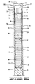
- FIGS. 1A-1C are perspective views of a cue stick of this invention.
- FIG. 2 is a sectional view of the tip end piece, inner core pin and sleeve of one embodiment of the inventive cue stick.
- FIG. 3A is a sectional view of the base shaft of this invention.
- FIG. 3B is a sectional view of the handle of the invention.
- FIG. 3C is a cross-sectional view taken along line 3C-3C of either FIG. 3A or FIG. 3B .
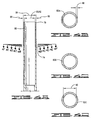
- FIG. 4A illustrates the sleeve of this invention.
- FIG. 4B is a cross-sectional view taken along line 4B-4B of FIG. 4A .
- FIG. 4C is a cross-sectional view taken along line 4C-4C of FIG. 4A .
- FIG. 4D is a cross-sectional view taken along line 4D-4D of FIG. 4A .
- FIG. 4E is a cross-sectional view taken along line 4E-4E of FIG. 4A .
- FIG. 4F is a cross-sectional view taken along line 4F-4F of FIG. 4A .
- FIG. 5 is a sectional view of another embodiment of the inventive cue stick.
- FIG. 6 is a cross-sectional view taken along line 6-6 of FIG. 5 .
- FIG. 7A illustrates a laminated dowel
- FIG. 7B is a cross-sectional view taken along line 7B-7B of FIG. 7A .
- FIG. 8 is a perspective view of a shaped rod used to make the base shaft of the inventive cue stick.
- FIG. 9 is a cross-sectional view of a component arrangement used to form a base shaft or handle of the inventive cue stick.
- FIG. 10 is another cross-sectional view of a component arrangement used to form a base shaft or handle of the inventive cue stick.
- FIG. 11 is yet another cross-sectional view of a component arrangement used to form a base shaft or handle of the inventive cue stick.
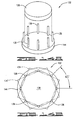
- FIG. 12 is a perspective view of a hexagonal press for manufacturing a base shaft or handle of the inventive cue stick.
- FIG. 13 is a cutting pattern for making multiple sleeves in accordance with the invention.
- FIG. 14A is a flat press for making the sleeve laminated starting block in accordance with the invention.
- FIG. 14B shows the layer placement in the flat press in accordance with the invention.
- the cue stick of this invention has an improved resistance to warping and a radially consistent feel and performance.
- the cue stick has dampened vibration and includes a tip end section that has a low mass, high strength and durability, and high performance characteristics.
- the cue stick 10 of this invention comprises a base shaft 12, a tip end piece 14, an inner core pin 16, and a sleeve 18.
- the base shaft 12 has a first end 20, a second end 22 opposed to the first end, an internal anchoring space 23 extending through the second end, and a longitudinal cavity 24 disposed between the first end 20 and the second end 22.
- the longitudinal cavity 24 extends at least 305 mm (12 inches), preferably at least 508 mm (20 inches), in length.
- the tip end piece 14 has a lower portion 26 extending through the second end 22 of the base shaft into the internal anchoring space 23 of the base shaft, an upper portion 28 spaced from the lower portion 26, and a bore 30 disposed between the lower portion 26 and the upper portion 28 and extending through the lower portion 26.
- the inner core pin 16 extends at one end 32 through the second end 22 of the base shaft into the internal anchoring space 23 of the base shaft, and extends at the other end 34 through the lower portion 26 of the tip end piece into the bore 30 of the tip end piece.
- the sleeve 18 extends around the upper portion 28 of the tip end piece.
- a cue tip 36 is attached to the tip end piece.
- the base shaft 12 may extend the entire length 37 of the cue stick, excluding the tip end length, as in FIG. 1A , or it may extend for a lesser portion 37' of the cue stick length, in which case a handle 38 is attached to the first end 20 of the base shaft at a joint 39 as shown in FIG. 1B .
- the "handle" is defined herein to include any portion of the cue stick attached to the base shaft first end 20.
- the use of joint 39 in a cue stick allows the player to separate the two pieces for ease in carrying and storing the cue stick.
- Another common configuration comprises two joints, 39 and 39' as shown in FIG. 1C .
- the handle comprises more than one longitudinal piece, namely handle piece 38a and handle piece 38b.
- joints 39 and 39' are bolt-type couplings allowing the handle to be readily engaged and disengaged.
- the handle may be a separate and previously existing handle.
- the handle is constructed according to this invention.
- the handle may additionally be covered by an outer veneer or sleeve comprising decorative material.
- one or more components of the inventive cue stick each comprise a plurality of longitudinal rounded sections 40 attached together.
- a "rounded" section means a section having only curved longitudinal surfaces, i.e., having no flat longitudinal surfaces.
- a component comprising rounded longitudinal sections has less of a tendency to warp, in part because the process of shaping the rounded sections results in less internal stress as will be described later.
- the rounded longitudinal sections have been formed by a stepwise removal of outer wood layers between two end points.
- the base shaft 12 and/or handle 38 preferably each include at least three longitudinal, rounded sections 40 attached together. More preferably, the base shaft 12 and/or handle 38 (or section thereof) each include six rounded sections attached together. Each section has a longitudinally extending concave surface 42, a longitudinally extending convex surface 44, and an arcuate outer surface 46. The concave surface 42 of each section abuts the convex surface 44 of an adjacent section.
- the longitudinal sections 40 are attached together with an adhesive. Examples of suitable adhesives for attaching the sections 40 together are epoxy resins, polyvinyl acetates, and polyurethane.
- the longitudinal rounded sections 40 are preferably made of wood.
- wood as used herein and in the appended claims is defined to include naturally fibrous materials such as hardwoods and bamboo, as well as synthetic fibrous materials having properties similar to wood.
- wood refers to naturally fibrous materials. Examples of suitable wood include, but are not limited to, maple, oak, birch, hickory, white ash, and black cherry.
- each section 40 is formed of multiple glued layers of hardwood.
- each section 40 is formed of laminated maple hardwood. When a laminated hardwood is used, preferably each layer has a thickness in the range of about 018 mm (1/32 inch) to about 312 mm (1/8 inch). More preferably the layers have a thickness of about 115 mm (1/16 inch).
- the wood used to form the rounded longitudinal sections 40 comprises elongated wood cell fibers arranged in a generally uniform orientation. Preferably the wood cell fiber orientation is aligned longitudinally in each longitudinal rounded section 40. If the wood is laminated, preferably each layer is also aligned longitudinally with the section 40.
- the wood used to form the longitudinal sections also has an end grain 50.
- the "end grain” 50 of a longitudinal section 40 is defined as the growth lines in the case of a section formed of a single piece of wood, and the glue lines in the case of a section formed of laminated wood.
- the "end grain direction" is defined as the direction of the growth lines in the case of a section made from a single piece of wood, or the direction of the glue lines in the case of a section made from laminated wood.
- the end grain direction of each section 40 varies from the end grain direction of adjacent sections 40. Varying the end grain direction of each section helps to achieve a more uniform radial distribution of the physical properties of the wood.
- the end grain direction of each section varies by at least 10 degrees from the end grain direction of the sections adjacent thereto. More preferably, the end grain direction varies by about (360/n) degrees, where n is the number of sections used to form the base shaft or handle.
- n is the number of sections used to form the base shaft or handle.
- the end grain of each section should vary by about (360/3) or 120 degrees from the adjacent sections.
- a longitudinal cavity 24 is dis osed between the first end 20 and the second end 22 of the base shaft 12 and extends at least 305 mm (12 inches) along the length of the base shaft. More preferably, the length 51 of the longitudinal cavity is at least 508 mm (20 inches). Preferably the longitudinal cavity diameter 48 is in the range of about 30% to about 80% of the base shaft diameter at the first end 20, and more preferably about 7,9 mm (5/16 inch). Similarly, as shown by FIG 3B , a longitudinal handle cavity 24' may be disposed along the length of the handle.
- the longitudinal cavity 24 and longitudinal handle cavity 24' can be left vacant to increase flexibility of the shaft or may be filled with a filling material.
- a filling material can be added to the cavity 24 and/or cavity 24' to increase the weight of the cue stick.
- the cavity 24 is filled with a vibration-dampening material to reduce the vibration felt by the player due to impacting a cue ball with the cue stick.
- the vibration-dampening material preferably has a high surface area that diffuses reflections and attenuates the vibration as it reflects off the surface. Examples of suitable dampening materials include, but are not limited to, cork, foam, sponge, and balsa wood.
- the tip end piece 14 of the cue stick 10 is shaped like a cylinder and has a first, open end 54 adjacent to the lower portion 26 of the tip end piece and a second, closed end 58 adjacent to the upper portion 28 of the tip end piece.
- the lower portion 26 extends through the second end 22 of the base shaft into the internal anchoring space 23 of the base shaft and is stopped by a first shoulder 62.
- a portion of an outside surface 64 of the tip end piece 14 is affixed to an inner surface 66 of the base shaft 12.
- the surfaces 64 and 66 are affixed using an adhesive. Examples of suitable adhesive include, but are not limited to, those described for gluing the longitudinal rounded sections 40 together.
- the tip end piece 14 is made of a material having a low specific gravity and a compression and bend strength slightly less than that of the shaft.
- suitable materials include, but are not limited to, basswood, aspen, black cottonwood, and butternut.
- the tip end piece 14 is made of basswood, and more preferably it is made of multiple layers of basswood sheet or veneer wherein the layers are adhesively adjoined.
- the thickness of the wood layers used for the tip end piece 14 is preferably in the range of about 0,8 mm (1/32 inch) to about 3,2 mm (1/8 inch).
- suitable adhesives include, but are not limited to, epoxy resins, polyvinyl acetates, and polyurethane.
- the inner core pin 16 extends at one end 32 through the second end 22 of the base shaft 12 into the internal anchoring space 23 of the base shaft, and is stopped by a second shoulder 68 or end 70.
- the inner core pin 16 extends at its other end 34 through the lower portion 26 of the tip end piece 14 and into the bore 30 of the tip end piece.
- a lower pin surface 72 is affixed to the inner surface 66 of the base shaft 12.
- An upper pin surface 56 is affixed to an inner surface 60 of the tip end piece bore.
- the surfaces 72 and 76 and the surfaces 56 and 60 are affixed using an adhesive. Examples of suitable adhesives are the same as described above for affixing the rounded longitudinal sections 40 together.
- the inner core pin 16 provides additional structural integrity and reinforces the surface adhesion of the tip end piece 14 to the base shaft 12.
- the inner core pin 16 is preferably composed of a material that is very light but still possesses a relatively high compressive and bending strength.
- the inner core pin material has a compressive strength of 10,34 mPa (1500 psi) or greater and a specific gravity of 0.3 or less, and more preferably is made of balsa wood.
- the sleeve 18 extends around the upper portion 28 of the tip end piece.
- the sleeve 18 functions to prevent splitting or spreading of the end of the cue stick 10.
- the sleeve 18 has a bottom edge 74 and a top edge 76 opposed to the bottom edge.
- the bottom edge 74 of the sleeve 18 abuts an edge 78 of the second end 22 of the base shaft 12.
- the bottom edge 74 of the sleeve 18 and the edge 78 of the base shaft 12 are adhesively attached together.
- an inner surface 80 of the sleeve 18 is adhesively attached to the outside surface 64 of the tip end piece 14.
- the top edge 76 of the sleeve 18 is flush with the closed, second end 58 of the tip end piece 14.
- the cue tip 36 is attached to the second end 58 of the tip end piece.
- the sleeve 18 preferably has a specific gravity less than 1.0. More importantly, the sleeve should also have a high band strength-to-weight ratio. To maximize the band strength, the wood cell fiber orientation in the installed sleeve 18 is preferably aligned in a plane substantially perpendicular to the longitudinal axis of the cue stick.
- the sleeve 18 is preferably formed of multiple laminations or veneers of wood, and more preferably of multiple laminations or veneers of a hardwood or bamboo. Suitable materials for the sleeve 18 include, but are not limited to, maple, bamboo, oak, birch, hickory, white ash and black cherry.
- the laminated sleeve is formed from thin hardwood layers or veneers, preferably between 0,5 mm (0.020 inch) and 1,5 mm (060 inch) thick, and more preferably between about 0,6 mm (0.025 inch) and 0,8 mm (0.030 inch) thick.
- the wood cell fibers of each layer should extend within the plane of the layer, and each layer is preferably oriented in a plane perpendicular to the longitudinal axis of the tip end piece 14.
- the wood cell fiber orientation of each layer varies from the fiber orientation of an adjacent layer; more preferably the wood cell fiber orientation of each layer varies by at least 10 degrees from the wood cell fiber orientation of an adjacent layer. Most preferably the wood cell fiber orientation of each layer varies by approximately 45 degrees from the wood cell fiber orientation of an adjacent layer.
- the laminated sleeve layers are arranged such that the fiber orientation of the middle layer(s) varies from the fiber orientation of both adjacent layers, more preferably by at least 10 degrees, and most preferably by about 45 degrees from the fiber orientation of both adjacent layers as shown in FIG. 4 .
- the fiber orientations 82A-82E are symbolized by lines in each of the layers portrayed in FIG. 4 .
- the fiber orientation of each layer varies by about 45 degrees from layer(s) adjacent thereto. In this way, the band strength is uniform in all radial directions.
- Each layer is preferably adhered to adjacent layer(s) with a thin coating of high strength adhesive.
- the sleeve comprises between 20 to 70 layers of wood.
- the sleeve length is in the range of about 25,4 mm (1.0 inch) to about 12,7 mm (5 inch).
- the outer diameter 84 of the sleeve should match the outer diameter 86 of the base shaft second end 22.
- the thickness of the sleeve wall 88 is preferably between about 0,6 mm (0.025 inch) and 1,5 mm (0.060 inch) and is determined by the desired band strength balanced with the desired tip section weight. The sleeve wall thickness 88 then sets or determines the inner diameter 90 of the sleeve which should match the inner diameter 92 of the base shaft second end.
- FIGS. 5 and 6 another preferred embodiment uses a solid laminated composite tip end piece 94.
- the composite tip end piece 94 has an upper portion 96 and a lower portion 98.
- the lower portion 98 extends through the second end 22 of the base shaft 12 into the internal anchoring space 23 of the base shaft and is stopped when the edge 78 of the base shaft 12 abuts an upper shoulder 100 of the composite tip end piece 94.
- a surface 106 of the lower portion 98 of the composite tip end piece 94 is preferably adhesively attached to the inner surface 66 of the base shaft 12.
- the sleeve 18 extends around the upper portion 96 of the composite tip end piece 94.
- the bottom edge 74 of the sleeve 18 abuts the edge 78 of the second end 22 of the base shaft 12.
- the bottom edge 74 of the sleeve 18 and the edge 78 of the base shaft 12 are adhesively attached together.
- the inner surface 80 of the sleeve 18 is adhesively attached to a surface 108 of the upper portion 96 of the composite tip end piece 94.
- the top edge 76 of the sleeve 18 is flush with a top end 110 of the composite tip end piece 94.
- the composite tip end piece 94 is made by adhesively combining layers of the material described above for the tip end piece, and layers of material described for the inner core pin 16, in a manner to produce a laminate sheet.
- the layers are alternated and made of balsa and basswood.
- the wood fibers in each layer are oriented parallel to the axis of the cue stick and the layer itself is in a plane parallel to the axis of the cue stick.
- the thickness of each wood layer used for the composite tip end piece is preferably in the range of about 0,4 mm (1/64 inch) to about 3,2 mm (1/8 inch).
- Suitable adhesives for adhesively combining the layers are the same as those described above.
- the dowel 112 can be made of any material, but preferably is made of hard wood. More preferably, the dowel 112 is made from multiple glued layers of hard wood. Most plywoods are manufactured with the fiber grain orientation varying from one layer to the next. In the present invention, however, preferably each layer is stacked such that the wood fibers are running in the same plane and in the same direction.
- Dowel blanks are machined from wood or layered hardwood such that the wood fibers run longitudinally.
- the blank is rounded using a lathe.
- the wood is allowed to relax between passes.
- the dowel made using this procedure is much straighter and has less tendency to warp than dowels made using conventional methods.
- each dowel 112 is grooved using any procedure known to those in the art, but preferably using a round nose cutter or router bit that is the same diameter as the dowel.
- This procedure converts each dowel 112 to a shaped rod 114 having a crescent shaped cross-section 116.
- Each shaped rod has a concave surface 42 and a convex surface 44.
- the radius of the convex cut is equal to the radius of the concave cut.
- Multiple shaped rods 114 are then coated with adhesive and arranged such that the concave surface 42 of each shaped rod abuts a convex surface 44 of an adjacent shaped rod to form a substantially solid bundle 117, examples of which are shown in FIGS. 9-11 .
- the grooves are preferably cut such that the end grain runs either parallel or perpendicular to a tangent at the center of the groove.
- the end grain of each shaped rod in FIG. 9 runs perpendicular to a tangent at the center of the groove.
- the end grain runs parallel to a tangent at the center of the grain. Either method assures that the shaped rods will bundle such that the end grain direction of each section uniformly varies from adjacent sections. Varying the end grain direction provides radial symmetry to the physical properties of the finished base shaft.
- the bundle 117 may be arranged leaving an axial hole 119 as shown in FIG. 9 , or with the sections meeting at the center as in FIGS. 10 and 11 .
- Any number of shaped rods can be bundled.
- six 12,7 mm (1 ⁇ 2-inch) diameter dowels are grooved to a depth of 4,4 mm (11/64 inch), coated with adhesive, bundled as in FIG. 9 , placed in a 1-1,6 mm (1-1/16 inch) hexagonal press 118.
- the bundle 117 is placed in a base 120 of the hexagonal press 118.
- the press top 122 fits such that bolts 124 protrude through bolt holes 126.
- the press is then securely closed and pressure uniformly applied by threading nuts (not shown) to a uniform tightness onto the bolts. After the adhesive has dried or cured, the nuts are removed and the top 122 lifted using handles 128 or the like.
- the bundle 117 is machined using a lathe to produce a smooth circular outer bundle circumference.
- the outer bundle circumference is then tapered by means known to those skilled in the art to produce a base shaft 12 tapered from the first end 20 to the second end 22.
- the longitudinal cavity 24 and/or 24' is drilled from either end of the base shaft or the handle and extends the desired length.
- the longitudinal cavity 24 and/or 24' may be created using a gun drill or any other technique such as is known in the art. If an axial hole 119 is formed in the bundle 117, the hole can serve as a pilot for drilling the longitudinal cavity 24.
- a laminated starting block is first formed from thin hardwood layers or veneers, each layer having a wood fiber orientation in the plane of the layer, and each layer being preferably between 0,5 mm (0.020 inch) and 1,5 mm (0.060 inch) thick, and more preferably between about 0,6 mm (0.025 inch) and 0,8 mm (0.030 inch) thick.
- Each layer is coated with a thin layer of a high strength adhesive. Examples of suitable adhesives are the same as described above.
- a cutting pattern 130 such as the pattern shown in FIG. 13 is attached to the bottom side of the first layer which is placed in a flat press 132 as shown in FIG. 14A .
- a second layer is coated with adhesive and placed with the adhesive side down onto the top of the first layer and so on.
- the coated layers are preferably stacked such that the wood fiber orientation of each wood layer varies from the wood fiber orientation of an adjacent layer; preferably the wood fiber orientation of each layer varies by at least 10 degrees from the wood fiber orientation of an adjacent layer.
- the flat press 132 shown in FIG. 14A assists in varying the fiber orientation of each layer by approximately 45 degrees from the fiber orientation of an adjacent layer.
- the corners 134 of each layer fit between press rods 136.
- the next layer is rotated 45 degrees, or a multiple of 45 degrees, and the corner 134' of the next layer may be placed as in FIG. 14B .
- plate 138 is placed on top and clamped to the flat press 132.
- the layers are allowed to dry or cure to produce a laminated starting block for the sleeve.
- Sleeves are machined making use of the cutting pattern 130 and using equipment and procedures known to those in the art.
- small holes are drilled using a drill press at each center mark 140 of the pattern attached to the laminated starting block.
- Square blanks are cut along lines 142 using, for example, a band saw; each blank is then rounded using, for example, a lathe.
- the small holes are then used as pilot holes to drill out the center and produce the sleeve.
- Preferred sleeve dimensions are as previously described.
Applications Claiming Priority (2)
| Application Number | Priority Date | Filing Date | Title |
|---|---|---|---|
| US11/076,833 US7507164B2 (en) | 2005-03-10 | 2005-03-10 | Cue stick and method of making same |
| PCT/US2006/007986 WO2006098941A2 (en) | 2005-03-10 | 2006-03-06 | Cue stick and method of making same |
Publications (3)
| Publication Number | Publication Date |
|---|---|
| EP1861181A2 EP1861181A2 (en) | 2007-12-05 |
| EP1861181A4 EP1861181A4 (en) | 2010-12-08 |
| EP1861181B1 true EP1861181B1 (en) | 2012-11-28 |
Family
ID=36971753
Family Applications (1)
| Application Number | Title | Priority Date | Filing Date |
|---|---|---|---|
| EP06748301A Not-in-force EP1861181B1 (en) | 2005-03-10 | 2006-03-06 | Cue stick and method of making same |
Country Status (6)
| Country | Link |
|---|---|
| US (1) | US7507164B2 (zh) |
| EP (1) | EP1861181B1 (zh) |
| JP (1) | JP4869328B2 (zh) |
| CN (1) | CN101128242B (zh) |
| CA (1) | CA2595941C (zh) |
| WO (1) | WO2006098941A2 (zh) |
Families Citing this family (15)
| Publication number | Priority date | Publication date | Assignee | Title |
|---|---|---|---|---|
| GB0022835D0 (en) * | 2000-09-18 | 2000-11-01 | Aventis Cropscience Sa | New herbicidal composition |
| US6966910B2 (en) * | 2002-04-05 | 2005-11-22 | Stephen Ritland | Dynamic fixation device and method of use |
| WO2003094699A2 (en) | 2002-05-08 | 2003-11-20 | Stephen Ritland | Dynamic fixation device and method of use |
| WO2008013693A1 (en) * | 2006-07-28 | 2008-01-31 | Clawson Custom Cues, Inc.D/B/A Predator Products | Cue stick |
| US20080132346A1 (en) * | 2006-11-02 | 2008-06-05 | Clawson Custom Cues, Inc. | Cue stick shaft |
| US20080160735A1 (en) * | 2006-12-28 | 2008-07-03 | Qimonda Ag | Forming Polysilicon Regions |
| CN201132057Y (zh) * | 2007-08-13 | 2008-10-15 | 张荣士 | 具芯管的撞球杆 |
| WO2009055806A1 (en) * | 2007-10-26 | 2009-04-30 | Owen D W | Cue stick, cue stick handle with rigid forearm and method of making the same |
| CN101721803A (zh) * | 2008-10-14 | 2010-06-09 | 张荣士 | 撞球杆前肢 |
| US8876618B1 (en) | 2013-10-16 | 2014-11-04 | Lienard Brown | Cue stick for billiards sports |
| CN103737020B (zh) * | 2013-11-25 | 2016-08-17 | 哈尔滨汽轮机厂有限责任公司 | 高温合金gh901材质的汽轮机主汽调节阀杆外圆的车削方法 |
| CN105451833A (zh) * | 2014-03-24 | 2016-03-30 | 克劳森手工球杆股份有限公司 | 球杆杆头插入物 |
| US9416931B1 (en) * | 2015-07-21 | 2016-08-16 | Larry D. Ross | Method of making a bamboo lamp or other item |
| CN105771283B (zh) * | 2016-03-10 | 2024-01-12 | 黄祥君 | 一种投掷吸盘飞镖及其标靶 |
| CN108525241A (zh) * | 2018-04-23 | 2018-09-14 | 中山市富达运动器材有限公司 | 一种减震式守门员冰球棍及其震动测试方法 |
Family Cites Families (24)
| Publication number | Priority date | Publication date | Assignee | Title |
|---|---|---|---|---|
| US132054A (en) * | 1872-10-08 | Improvement in billiard-cues | ||
| US672646A (en) * | 1900-10-24 | 1901-04-23 | Harry E Mereness Jr | Billiard-cue. |
| GB190501809A (en) * | 1905-01-30 | 1905-09-14 | Frederick John Williams | An Improved Cue for Billiards and similar Games |
| US941728A (en) * | 1907-05-03 | 1909-11-30 | Richard Jah Preast | Cue. |
| US951453A (en) * | 1909-05-28 | 1910-03-08 | Burroughes & Watts Ltd | Billiard-cue. |
| US1241194A (en) * | 1915-06-07 | 1917-09-25 | Albert Pick & Company | Manufacture of billiard-cues. |
| US1210076A (en) * | 1916-04-10 | 1916-12-26 | Harry A Jost | Reinforced ferrule for cues. |
| US1248634A (en) * | 1916-05-10 | 1917-12-04 | Andrew D Du Bose | Billiard-cue. |
| GB180514A (en) * | 1921-04-14 | 1922-06-01 | Henry Edgar Davies | Improvements in billiard cues |
| US1505609A (en) * | 1922-06-16 | 1924-08-19 | Charles E Seeman | Sectional billiard cue |
| US1565612A (en) * | 1925-03-20 | 1925-12-15 | Ajello Vincent | Cue tip |
| JPS5530016A (en) * | 1978-08-19 | 1980-03-03 | Amino Tekko Kk | Pillarrlike material and making method thereof |
| JPH03239501A (ja) * | 1990-02-15 | 1991-10-25 | Yoshihisa Koyama | 多角形中空シャフト並びにその製造方法並びに複層シャフト部材の製造方法並びに多角形シャフト並びにシャフトの握部並びに円形シャフト並びに中空シャフト用節部材及びシャフトの継手 |
| US6110051A (en) * | 1997-11-25 | 2000-08-29 | Lorraine C. Mccarty Trust | Billiard cue |
| US5725437A (en) * | 1994-09-29 | 1998-03-10 | Lorraine C. McCarty | Billiard/pool cue |
| US5820473A (en) * | 1996-04-25 | 1998-10-13 | Lambros; Michael | Billard cue with improved joints for greater stability |
| US6132321A (en) * | 1996-07-17 | 2000-10-17 | Wethered; William | Cue stick joint and interchangeable cue |
| US5749788A (en) * | 1996-12-12 | 1998-05-12 | Bourque; Daniel R. | Tunable joint for a pool cue having compressive inserts |
| US6736733B2 (en) * | 1999-01-08 | 2004-05-18 | Kuo-Pin Yu | On billiard cue |
| US20020072423A1 (en) * | 2000-12-07 | 2002-06-13 | Pot Rick D. | Billiard cue stick |
| US20020082098A1 (en) * | 2000-12-21 | 2002-06-27 | Shih-Chuan Lai Chuang | Tubular exercise member having a wooden layer and a method for making the same |
| US20020132677A1 (en) * | 2001-03-14 | 2002-09-19 | Jung-Shih Chang | Billiard cue having an improved shaft |
| CA2414550C (en) * | 2002-12-13 | 2006-08-15 | Sam Miksym Nazaruk | Cue, super-shaft |
| US6869370B2 (en) * | 2003-05-08 | 2005-03-22 | Yeghia Davtyan | Laminated cue with central elongated member |
-
2005
- 2005-03-10 US US11/076,833 patent/US7507164B2/en not_active Expired - Fee Related
-
2006
- 2006-03-06 CN CN2006800057075A patent/CN101128242B/zh not_active Expired - Fee Related
- 2006-03-06 EP EP06748301A patent/EP1861181B1/en not_active Not-in-force
- 2006-03-06 JP JP2008500821A patent/JP4869328B2/ja not_active Expired - Fee Related
- 2006-03-06 CA CA2595941A patent/CA2595941C/en not_active Expired - Fee Related
- 2006-03-06 WO PCT/US2006/007986 patent/WO2006098941A2/en active Application Filing
Also Published As
| Publication number | Publication date |
|---|---|
| CA2595941A1 (en) | 2006-09-21 |
| JP4869328B2 (ja) | 2012-02-08 |
| US7507164B2 (en) | 2009-03-24 |
| EP1861181A4 (en) | 2010-12-08 |
| JP2008532633A (ja) | 2008-08-21 |
| CA2595941C (en) | 2012-07-17 |
| EP1861181A2 (en) | 2007-12-05 |
| CN101128242A (zh) | 2008-02-20 |
| US20060205525A1 (en) | 2006-09-14 |
| WO2006098941A3 (en) | 2007-05-31 |
| CN101128242B (zh) | 2012-04-25 |
| WO2006098941A2 (en) | 2006-09-21 |
Similar Documents
| Publication | Publication Date | Title |
|---|---|---|
| EP1861181B1 (en) | Cue stick and method of making same | |
| US5800293A (en) | Laminated wood bat and method of making same | |
| FI113014B (fi) | Menetelmä jääkiekko- tai vastaavan mailan lavan valmistamiseksi sekä mailan lapa ja lapaydin | |
| US8075414B2 (en) | Cue stick and cue stick handle with rigid forearm and method of making the same | |
| US6010417A (en) | Baseball bat | |
| US20020037780A1 (en) | Hockey stick with reinforced shaft | |
| US8834305B2 (en) | Reinforced bamboo lacrosse shaft | |
| KR100671880B1 (ko) | 적층 구조형 단풍나무 야구 배트 | |
| US8409038B2 (en) | Baseball bat | |
| CN102940961A (zh) | 竹木乒乓球拍底板及制作方法 | |
| US4968032A (en) | Hockey stick shaft | |
| US8808120B2 (en) | Bamboo lacrosse shaft | |
| US20050124441A1 (en) | Spiral wound laminate wood and method for construction | |
| US7297068B2 (en) | Vibration damping for a cue stick | |
| KR102061248B1 (ko) | 당구 큐의 휨 방지와 타격력이 향상된 큐대와 그 제조방법 | |
| US8795107B2 (en) | Symmetrical wood composite bat | |
| KR100436625B1 (ko) | 휨 발생이 없는 당구용 큐우 | |
| US2618481A (en) | Laminated bowling pin | |
| CA1310674C (en) | Reinforced hockey stick | |
| CN113681669B (zh) | 竹枪钉及其生产方法 | |
| WO2021059802A1 (ja) | バドミントンラケット | |
| CN203886145U (zh) | 球棒 | |
| US20100240467A1 (en) | Domed tip pads for cue sticks and cue sticks having same | |
| JPS6171075A (ja) | バツト | |
| IE20090135A1 (en) | A hurley stick |
Legal Events
| Date | Code | Title | Description |
|---|---|---|---|
| PUAI | Public reference made under article 153(3) epc to a published international application that has entered the european phase |
Free format text: ORIGINAL CODE: 0009012 |
|
| 17P | Request for examination filed |
Effective date: 20070809 |
|
| AK | Designated contracting states |
Kind code of ref document: A2 Designated state(s): AT BE BG CH CY CZ DE DK EE ES FI FR GB GR HU IE IS IT LI LT LU LV MC NL PL PT RO SE SI SK TR |
|
| AX | Request for extension of the european patent |
Extension state: AL BA HR MK YU |
|
| DAX | Request for extension of the european patent (deleted) | ||
| A4 | Supplementary search report drawn up and despatched |
Effective date: 20101110 |
|
| GRAP | Despatch of communication of intention to grant a patent |
Free format text: ORIGINAL CODE: EPIDOSNIGR1 |
|
| GRAS | Grant fee paid |
Free format text: ORIGINAL CODE: EPIDOSNIGR3 |
|
| GRAA | (expected) grant |
Free format text: ORIGINAL CODE: 0009210 |
|
| AK | Designated contracting states |
Kind code of ref document: B1 Designated state(s): AT BE BG CH CY CZ DE DK EE ES FI FR GB GR HU IE IS IT LI LT LU LV MC NL PL PT RO SE SI SK TR |
|
| REG | Reference to a national code |
Ref country code: GB Ref legal event code: FG4D |
|
| REG | Reference to a national code |
Ref country code: CH Ref legal event code: EP |
|
| REG | Reference to a national code |
Ref country code: AT Ref legal event code: REF Ref document number: 585824 Country of ref document: AT Kind code of ref document: T Effective date: 20121215 |
|
| REG | Reference to a national code |
Ref country code: IE Ref legal event code: FG4D |
|
| REG | Reference to a national code |
Ref country code: DE Ref legal event code: R096 Ref document number: 602006033341 Country of ref document: DE Effective date: 20130124 |
|
| REG | Reference to a national code |
Ref country code: AT Ref legal event code: MK05 Ref document number: 585824 Country of ref document: AT Kind code of ref document: T Effective date: 20121128 |
|
| REG | Reference to a national code |
Ref country code: NL Ref legal event code: VDEP Effective date: 20121128 |
|
| REG | Reference to a national code |
Ref country code: LT Ref legal event code: MG4D |
|
| PG25 | Lapsed in a contracting state [announced via postgrant information from national office to epo] |
Ref country code: ES Free format text: LAPSE BECAUSE OF FAILURE TO SUBMIT A TRANSLATION OF THE DESCRIPTION OR TO PAY THE FEE WITHIN THE PRESCRIBED TIME-LIMIT Effective date: 20130311 Ref country code: LT Free format text: LAPSE BECAUSE OF FAILURE TO SUBMIT A TRANSLATION OF THE DESCRIPTION OR TO PAY THE FEE WITHIN THE PRESCRIBED TIME-LIMIT Effective date: 20121128 Ref country code: FI Free format text: LAPSE BECAUSE OF FAILURE TO SUBMIT A TRANSLATION OF THE DESCRIPTION OR TO PAY THE FEE WITHIN THE PRESCRIBED TIME-LIMIT Effective date: 20121128 Ref country code: SE Free format text: LAPSE BECAUSE OF FAILURE TO SUBMIT A TRANSLATION OF THE DESCRIPTION OR TO PAY THE FEE WITHIN THE PRESCRIBED TIME-LIMIT Effective date: 20121128 |
|
| PGFP | Annual fee paid to national office [announced via postgrant information from national office to epo] |
Ref country code: GB Payment date: 20130107 Year of fee payment: 8 Ref country code: DE Payment date: 20130110 Year of fee payment: 8 |
|
| PG25 | Lapsed in a contracting state [announced via postgrant information from national office to epo] |
Ref country code: BE Free format text: LAPSE BECAUSE OF FAILURE TO SUBMIT A TRANSLATION OF THE DESCRIPTION OR TO PAY THE FEE WITHIN THE PRESCRIBED TIME-LIMIT Effective date: 20121128 Ref country code: PT Free format text: LAPSE BECAUSE OF FAILURE TO SUBMIT A TRANSLATION OF THE DESCRIPTION OR TO PAY THE FEE WITHIN THE PRESCRIBED TIME-LIMIT Effective date: 20130328 Ref country code: PL Free format text: LAPSE BECAUSE OF FAILURE TO SUBMIT A TRANSLATION OF THE DESCRIPTION OR TO PAY THE FEE WITHIN THE PRESCRIBED TIME-LIMIT Effective date: 20121128 Ref country code: SI Free format text: LAPSE BECAUSE OF FAILURE TO SUBMIT A TRANSLATION OF THE DESCRIPTION OR TO PAY THE FEE WITHIN THE PRESCRIBED TIME-LIMIT Effective date: 20121128 Ref country code: GR Free format text: LAPSE BECAUSE OF FAILURE TO SUBMIT A TRANSLATION OF THE DESCRIPTION OR TO PAY THE FEE WITHIN THE PRESCRIBED TIME-LIMIT Effective date: 20130301 Ref country code: LV Free format text: LAPSE BECAUSE OF FAILURE TO SUBMIT A TRANSLATION OF THE DESCRIPTION OR TO PAY THE FEE WITHIN THE PRESCRIBED TIME-LIMIT Effective date: 20121128 |
|
| PG25 | Lapsed in a contracting state [announced via postgrant information from national office to epo] |
Ref country code: AT Free format text: LAPSE BECAUSE OF FAILURE TO SUBMIT A TRANSLATION OF THE DESCRIPTION OR TO PAY THE FEE WITHIN THE PRESCRIBED TIME-LIMIT Effective date: 20121128 |
|
| PG25 | Lapsed in a contracting state [announced via postgrant information from national office to epo] |
Ref country code: SK Free format text: LAPSE BECAUSE OF FAILURE TO SUBMIT A TRANSLATION OF THE DESCRIPTION OR TO PAY THE FEE WITHIN THE PRESCRIBED TIME-LIMIT Effective date: 20121128 Ref country code: CZ Free format text: LAPSE BECAUSE OF FAILURE TO SUBMIT A TRANSLATION OF THE DESCRIPTION OR TO PAY THE FEE WITHIN THE PRESCRIBED TIME-LIMIT Effective date: 20121128 Ref country code: EE Free format text: LAPSE BECAUSE OF FAILURE TO SUBMIT A TRANSLATION OF THE DESCRIPTION OR TO PAY THE FEE WITHIN THE PRESCRIBED TIME-LIMIT Effective date: 20121128 Ref country code: DK Free format text: LAPSE BECAUSE OF FAILURE TO SUBMIT A TRANSLATION OF THE DESCRIPTION OR TO PAY THE FEE WITHIN THE PRESCRIBED TIME-LIMIT Effective date: 20121128 Ref country code: BG Free format text: LAPSE BECAUSE OF FAILURE TO SUBMIT A TRANSLATION OF THE DESCRIPTION OR TO PAY THE FEE WITHIN THE PRESCRIBED TIME-LIMIT Effective date: 20130228 |
|
| PG25 | Lapsed in a contracting state [announced via postgrant information from national office to epo] |
Ref country code: IT Free format text: LAPSE BECAUSE OF FAILURE TO SUBMIT A TRANSLATION OF THE DESCRIPTION OR TO PAY THE FEE WITHIN THE PRESCRIBED TIME-LIMIT Effective date: 20121128 Ref country code: RO Free format text: LAPSE BECAUSE OF FAILURE TO SUBMIT A TRANSLATION OF THE DESCRIPTION OR TO PAY THE FEE WITHIN THE PRESCRIBED TIME-LIMIT Effective date: 20121128 Ref country code: NL Free format text: LAPSE BECAUSE OF FAILURE TO SUBMIT A TRANSLATION OF THE DESCRIPTION OR TO PAY THE FEE WITHIN THE PRESCRIBED TIME-LIMIT Effective date: 20121128 |
|
| PLBE | No opposition filed within time limit |
Free format text: ORIGINAL CODE: 0009261 |
|
| STAA | Information on the status of an ep patent application or granted ep patent |
Free format text: STATUS: NO OPPOSITION FILED WITHIN TIME LIMIT |
|
| PG25 | Lapsed in a contracting state [announced via postgrant information from national office to epo] |
Ref country code: MC Free format text: LAPSE BECAUSE OF NON-PAYMENT OF DUE FEES Effective date: 20130331 |
|
| REG | Reference to a national code |
Ref country code: CH Ref legal event code: PL |
|
| 26N | No opposition filed |
Effective date: 20130829 |
|
| PG25 | Lapsed in a contracting state [announced via postgrant information from national office to epo] |
Ref country code: CY Free format text: LAPSE BECAUSE OF FAILURE TO SUBMIT A TRANSLATION OF THE DESCRIPTION OR TO PAY THE FEE WITHIN THE PRESCRIBED TIME-LIMIT Effective date: 20121128 |
|
| REG | Reference to a national code |
Ref country code: DE Ref legal event code: R097 Ref document number: 602006033341 Country of ref document: DE Effective date: 20130829 |
|
| REG | Reference to a national code |
Ref country code: FR Ref legal event code: ST Effective date: 20131129 |
|
| REG | Reference to a national code |
Ref country code: IE Ref legal event code: MM4A |
|
| PG25 | Lapsed in a contracting state [announced via postgrant information from national office to epo] |
Ref country code: LI Free format text: LAPSE BECAUSE OF NON-PAYMENT OF DUE FEES Effective date: 20130331 Ref country code: CH Free format text: LAPSE BECAUSE OF NON-PAYMENT OF DUE FEES Effective date: 20130331 Ref country code: IE Free format text: LAPSE BECAUSE OF NON-PAYMENT OF DUE FEES Effective date: 20130306 Ref country code: FR Free format text: LAPSE BECAUSE OF NON-PAYMENT OF DUE FEES Effective date: 20130402 |
|
| REG | Reference to a national code |
Ref country code: DE Ref legal event code: R119 Ref document number: 602006033341 Country of ref document: DE |
|
| GBPC | Gb: european patent ceased through non-payment of renewal fee |
Effective date: 20140306 |
|
| REG | Reference to a national code |
Ref country code: DE Ref legal event code: R119 Ref document number: 602006033341 Country of ref document: DE Effective date: 20141001 |
|
| PG25 | Lapsed in a contracting state [announced via postgrant information from national office to epo] |
Ref country code: DE Free format text: LAPSE BECAUSE OF NON-PAYMENT OF DUE FEES Effective date: 20141001 Ref country code: GB Free format text: LAPSE BECAUSE OF NON-PAYMENT OF DUE FEES Effective date: 20140306 |
|
| PG25 | Lapsed in a contracting state [announced via postgrant information from national office to epo] |
Ref country code: TR Free format text: LAPSE BECAUSE OF FAILURE TO SUBMIT A TRANSLATION OF THE DESCRIPTION OR TO PAY THE FEE WITHIN THE PRESCRIBED TIME-LIMIT Effective date: 20121128 |
|
| PG25 | Lapsed in a contracting state [announced via postgrant information from national office to epo] |
Ref country code: HU Free format text: LAPSE BECAUSE OF FAILURE TO SUBMIT A TRANSLATION OF THE DESCRIPTION OR TO PAY THE FEE WITHIN THE PRESCRIBED TIME-LIMIT; INVALID AB INITIO Effective date: 20060306 Ref country code: LU Free format text: LAPSE BECAUSE OF NON-PAYMENT OF DUE FEES Effective date: 20130306 |
|
| PG25 | Lapsed in a contracting state [announced via postgrant information from national office to epo] |
Ref country code: IS Free format text: LAPSE BECAUSE OF FAILURE TO SUBMIT A TRANSLATION OF THE DESCRIPTION OR TO PAY THE FEE WITHIN THE PRESCRIBED TIME-LIMIT Effective date: 20121128 |