EP1858304A2 - Elektronisches Vorschaltgerät und Verfahren zum Betreiben eines elektronisches Vorschaltsgerät - Google Patents
Elektronisches Vorschaltgerät und Verfahren zum Betreiben eines elektronisches Vorschaltsgerät Download PDFInfo
- Publication number
- EP1858304A2 EP1858304A2 EP07107311A EP07107311A EP1858304A2 EP 1858304 A2 EP1858304 A2 EP 1858304A2 EP 07107311 A EP07107311 A EP 07107311A EP 07107311 A EP07107311 A EP 07107311A EP 1858304 A2 EP1858304 A2 EP 1858304A2
- Authority
- EP
- European Patent Office
- Prior art keywords
- electronic ballast
- microprocessor
- terminals
- combination signal
- signal
- Prior art date
- Legal status (The legal status is an assumption and is not a legal conclusion. Google has not performed a legal analysis and makes no representation as to the accuracy of the status listed.)
- Granted
Links
Images

Classifications
-
- H—ELECTRICITY
- H05—ELECTRIC TECHNIQUES NOT OTHERWISE PROVIDED FOR
- H05B—ELECTRIC HEATING; ELECTRIC LIGHT SOURCES NOT OTHERWISE PROVIDED FOR; CIRCUIT ARRANGEMENTS FOR ELECTRIC LIGHT SOURCES, IN GENERAL
- H05B41/00—Circuit arrangements or apparatus for igniting or operating discharge lamps
- H05B41/14—Circuit arrangements
- H05B41/26—Circuit arrangements in which the lamp is fed by power derived from DC by means of a converter, e.g. by high-voltage DC
- H05B41/28—Circuit arrangements in which the lamp is fed by power derived from DC by means of a converter, e.g. by high-voltage DC using static converters
- H05B41/295—Circuit arrangements in which the lamp is fed by power derived from DC by means of a converter, e.g. by high-voltage DC using static converters with semiconductor devices and specially adapted for lamps with preheating electrodes, e.g. for fluorescent lamps
- H05B41/298—Arrangements for protecting lamps or circuits against abnormal operating conditions
- H05B41/2981—Arrangements for protecting lamps or circuits against abnormal operating conditions for protecting the circuit against abnormal operating conditions
- H05B41/2985—Arrangements for protecting lamps or circuits against abnormal operating conditions for protecting the circuit against abnormal operating conditions against abnormal lamp operating conditions
-
- H—ELECTRICITY
- H05—ELECTRIC TECHNIQUES NOT OTHERWISE PROVIDED FOR
- H05B—ELECTRIC HEATING; ELECTRIC LIGHT SOURCES NOT OTHERWISE PROVIDED FOR; CIRCUIT ARRANGEMENTS FOR ELECTRIC LIGHT SOURCES, IN GENERAL
- H05B41/00—Circuit arrangements or apparatus for igniting or operating discharge lamps
- H05B41/14—Circuit arrangements
- H05B41/26—Circuit arrangements in which the lamp is fed by power derived from DC by means of a converter, e.g. by high-voltage DC
- H05B41/28—Circuit arrangements in which the lamp is fed by power derived from DC by means of a converter, e.g. by high-voltage DC using static converters
- H05B41/282—Circuit arrangements in which the lamp is fed by power derived from DC by means of a converter, e.g. by high-voltage DC using static converters with semiconductor devices
- H05B41/285—Arrangements for protecting lamps or circuits against abnormal operating conditions
- H05B41/2851—Arrangements for protecting lamps or circuits against abnormal operating conditions for protecting the circuit against abnormal operating conditions
- H05B41/2855—Arrangements for protecting lamps or circuits against abnormal operating conditions for protecting the circuit against abnormal operating conditions against abnormal lamp operating conditions
-
- Y—GENERAL TAGGING OF NEW TECHNOLOGICAL DEVELOPMENTS; GENERAL TAGGING OF CROSS-SECTIONAL TECHNOLOGIES SPANNING OVER SEVERAL SECTIONS OF THE IPC; TECHNICAL SUBJECTS COVERED BY FORMER USPC CROSS-REFERENCE ART COLLECTIONS [XRACs] AND DIGESTS
- Y02—TECHNOLOGIES OR APPLICATIONS FOR MITIGATION OR ADAPTATION AGAINST CLIMATE CHANGE
- Y02B—CLIMATE CHANGE MITIGATION TECHNOLOGIES RELATED TO BUILDINGS, e.g. HOUSING, HOUSE APPLIANCES OR RELATED END-USER APPLICATIONS
- Y02B20/00—Energy efficient lighting technologies, e.g. halogen lamps or gas discharge lamps
Definitions
- the present invention relates to an electronic ballast having a microprocessor, at least one first terminal for connecting a supply voltage, a plurality of second terminals for connecting at least one light source, wherein the second terminals are coupled to the microprocessor. It also relates to a method for operating such a ballast.
- the present invention initially relates to a problem of manual or automatic wiring in luminaires.
- luminaires usually include all those elements which belong to receive and operate a lamp, for example an electronic ballast, the lamp itself, reflectors, sockets etc.
- a luminaire manufacturer purchases lamps and electronic ballasts and assembles them in a housing. which is designed according to his own wishes.
- the advantage here is that electronic ballasts are standardized and thus interchangeable.
- the electronic ballast and the at least one lamp are at least partially wired manually in the luminaire manufacturer. Especially if several lamps to be connected to an electronic ballast, there is a risk of incorrect contacting, in particular by confusing the order of the connections.
- the object of the present invention is therefore to develop an electronic ballast of the type mentioned above and a corresponding method for operating such an electronic ballast such that the risk of lamp early failure can be reduced.
- the present invention is based on the knowledge to use the already existing microprocessor to the voltage applied to at least two of the second terminals Combining signals to generate at least one combination signal. If a table is then stored in the electronic ballast in which a desired value range of the at least one combination signal is stored, the actual value of the at least one combination signal can be compared with the corresponding desired value range of the at least one combination signal by means of the microprocessor. If the actual value is outside the setpoint range, there is either incorrect wiring or at least one light source with the wrong nominal power is used.
- a specification of the error can be made depending on the measured actual value. In the case of a first set of actual values or actual value ranges, there is a false wiring; with a second set of actual values or actual value ranges, at least one of the light sources used has an incorrect nominal power.
- microprocessor may be provided for the tasks to be performed by a microprocessor within the scope of the present invention
- an already existing microprocessor is often already used, as mentioned. This is due to the fact that electronic ballasts are often designed by adjusting the parameters of the signal provided at its output for the operation of a variety of different lamps. The parameters to be varied as a function of the connected lamp are, for example, power, operating frequency, etc. Accordingly, such a microprocessor is already designed for determining the lamp or lamps connected to the electronic ballast, relevant lamp operating data, such as currents, Check voltages, resistances, across the multitude of second terminals with the lamp or lamps connected.
- a particularly preferred embodiment of the present invention is characterized in that the microprocessor is further designed to cause the output of an alarm signal, in particular in the form of an acoustic and / or optical and / or logical signal, when the actual value of the at least one combination signal outside the corresponding setpoint range of the at least one combination signal is located.
- an operator or a test device of an automatic production can be informed immediately after the incorrect wiring of the at least one lamp or immediately after the onset of a light source with the wrong nominal power and be prompted to correct the error.
- the electronic ballast preferably has at least one information connection, in particular at least one DALI (Digital Addressable Lighting Interface) bus connection, for causing the output of the alarm signal.
- DALI Digital Addressable Lighting Interface
- the alarm signal comprises the information that the light source is incorrectly connected to the electronic ballast, in particular, which of the second terminals are incorrectly connected to the at least one light source. This allows the operator to quickly correct the miswiring in a variety of second ports.
- the alarm signal may further comprise the information that the at least one light source or, in the case of multiple light sources, at least one light source has a wrong rated power.
- the signal present at a second connection can be described by a multiplicity of parameters, wherein the microprocessor is designed to form at least the difference of the values of a parameter of two signals in order to generate the at least one combination signal.
- the at least one combination signal corresponds to the electrical resistance between the two relevant terminals.
- the combination signal may represent another electrical characteristic, such as current, voltage, capacitance or inductance.
- the microprocessor is designed to generate the at least one combination signal when connected, but not yet ignited light source.
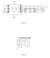
- an electronic ballast 100 is shown with a microprocessor 102, which is wired to a first lamp La1 and a second lamp La2.
- the electronic ballast 100 has on the input side a supply voltage connection for a supply voltage U N , which is formed by the terminals 1 and 2. The connections 3 and 5 are not used.
- Terminal 4 is intended for connection to the ground potential.
- Terminal 6 is provided for DALI terminal DA (-), while terminal 7 is for DALI terminal DA (+).
- the electronic ballast 100 is connected to the two lamps La1, La2.
- the lamp La1 has terminals a, b, c, d, while the lamp La2 terminals e, f, g, h has.
- the common lamp line L1 is connected to the terminal 21 of the electronic ballast 100.
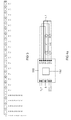
- FIG. 2 shows a table in which the terminals of the electronic ballast are indicated above, wherein in the table the connection of the respective lamp La1, La2 is indicated, which is connected to the corresponding terminal of the electronic ballast 100. There are eight correct combinations, see lines 1 to 8 of the table in FIG. 2.
- FIG. 3 shows a table indicating the ohmic resistance to be measured, which can be measured in accordance with the wiring variants given in FIG. 2 between the respective two terminals, which are indicated in the heading of the table in FIG.
- the value "R" corresponds to the ohmic resistance of the filament electrode of a lamp La1, La2. 2
- the value R between terminals 21 and 22 corresponds to the ohmic resistance of the filament electrode of a lamp La1, La2. 2
- the value R between terminals 21 and 23 the value R between terminals 21 and 23, the value R between terminals 24 and 25, and between terminals 26 results and 27, the value R.
- the resistance measured between all the other combinations of terminals 21 to 27 of the electronic ballast 100 is ⁇ .
- the electronic ballast corresponds to the electronic ballast of FIG. 1 and the lamps La1, La2 correspond to those of FIG. 1. They will therefore not be described again.
- Fig. 1 is the wiring of the common line L1.
- the common line L1 is connected to the terminal 23 of the electronic ballast 100, while in Fig. 4b, the common line L1 is connected to the terminal 22 of the electronic ballast 100.
- Such miswiring would result in lamp blackout and early lamp failure.
- FIG. 5 corresponds to the table of Fig. 2, wherein now false combinations are listed.
- Line 1 corresponds to the wiring variant shown in FIG. 4a
- line 2 corresponds to the wiring variant shown in FIG. 4b.
- Other incorrectly wired variants are possible, but are not listed for the sake of clarity.
- Fig. 6 corresponds to the table of Fig. 3, wherein in line 1 to be measured between the respective terminals ohmic resistances for the wiring variant of Fig. 4a and in line 2 for the wiring variant of Fig. 4b to be measured ohmic resistances are reproduced.
- an ohmic resistance of "2R” can therefore be measured between the terminals 21 and 22 in the wiring variant of FIG. 4a.
- a comparison with the ohmic resistors to be measured for correct combinations according to FIG. 3 shows that this is clearly to be regarded as an indication of a false wiring.
- a value of "2R" can also be measured for the wiring variant of FIG. 4b between the terminals 21 and 23, see line 2 of the table of FIG. 6, which in turn is a clear indication of a false wiring.
- the electronic ballast 100 Upon detection of a miswiring by comparing the measured resistance values, see FIGS. 3 and 6, with the resistance values of a table stored in the electronic ballast 100 defining a setpoint range, for example +/- 10% of the optimum setpoint, it can be determined whether there is wrong or correct wiring. In the event of a detected incorrect wiring, the output of an alarm signal can be initiated via the DALI bus connection DA (-) and DA (+). Alternatively to the output of an alarm signal via the DALI bus connection DA (-), DA (+), the at least one lamp La1, La2 can also be controlled by the electronic ballast 100 in such a way that it flashes. As a result, the operator is also informed quickly and easily about the presence of a false wiring.
Landscapes
- Circuit Arrangement For Electric Light Sources In General (AREA)
- Keying Circuit Devices (AREA)
- Electronic Switches (AREA)
- Discharge-Lamp Control Circuits And Pulse- Feed Circuits (AREA)
- Circuit Arrangements For Discharge Lamps (AREA)
- Arrangement Of Elements, Cooling, Sealing, Or The Like Of Lighting Devices (AREA)
Abstract
Description
- Die vorliegende Erfindung betrifft ein elektronisches Vorschaltgerät mit einem Mikroprozessor, mindestens einem ersten Anschluss zum Anschließen einer Versorgungsspannung, einer Vielzahl von zweiten Anschlüssen zum Anschließen mindestens einer Lichtquelle, wobei die zweiten Anschlüsse mit dem Mikroprozessor gekoppelt sind. Sie betrifft überdies ein Verfahren zum Betreiben eines derartigen Vorschaltgeräts.
- Die vorliegende Erfindung betrifft zunächst ein Problem der manuellen oder automatischen Verdrahtung in Leuchten. Leuchten umfassen dabei üblicherweise alle diejenigen Elemente, die dazugehören, um eine Lampe aufzunehmen und zu betreiben, beispielsweise ein elektronisches Vorschaltgerät, die Lampe selbst, Reflektoren, Fassungen, etc. Häufig bezieht dabei ein Leuchtenhersteller Lampen und elektronische Vorschaltgeräte und montiert diese in einem Gehäuse, das nach seinen eigenen Wünschen gestaltet ist. Vorteilhaft hierbei ist, dass elektronische Vorschaltgeräte genormt und damit austauschbar sind. Bei der Herstellung der Leuchte werden beim Leuchtenhersteller das elektronische Vorschaltgerät und die mindestens eine Lampe zumindest zum Teil manuell verdrahtet. Besonders wenn mehrere Lampen mit einem elektronischen Vorschaltgerät verbunden werden sollen, besteht die Gefahr einer falschen Kontaktierung, insbesondere durch Verwechslung der Reihenfolge der Anschlüsse. Dies führt im ungünstigsten Fall dazu, dass ein Lampenbetrieb nicht möglich wird. Diese Art von Fehler kann jedoch in einem Test schnell erkannt werden. Deutlich problematischer sind Fehler, die sich durch eine falsche Kontaktierung ergeben, bei denen die Lampen gezündet werden können und Licht abgeben. Da derartige Fehler häufig erst durch Kundenreklamation nach mehreren 100 Std. Betriebsdauer auffallen, muss dann vor Ort der Fehler behoben werden. Da sich die Lampen dann bereits aufgrund der Falschverdrahtung und des damit einhergehenden Betriebs mit nicht für den Betrieb zugelassenen Parametern an ihrem Lebensdauerende befinden, müssen die Lampen bzw. Leuchten dann vielfach ausgetauscht werden. Je nach Zugänglichkeit der Leuchte, wobei hier insbesondere die Einbauhöhe, die Einbausituation sowie die Anzahl der eingebauten Lampen bzw. Leuchten von Bedeutung sind, kann eine Behebung des Fehlers sehr kostspielig und sehr zeitaufwändig werden.
- Durch eine fehlerhafte, leuchteninterne Verdrahtung kann es beispielsweise bei Leuchten mit zwei Lampen zu einer Verdoppelung des Lampenstroms über einer Lampenelektrode kommen, was in einem Lampenfrühausfall nach bereits einem wenigen hundert Betriebsstunden resultiert.
- Ähnliche Folgen ergeben sich, wenn mindestens eine für das elektronische Vorschaltgerät ungeeignete Lampe bei ansonsten technisch richtiger Verdrahtung zwischen Lampe und elektronischem Vorschaltgerät eingesetzt und betrieben wird. Beispielsweise können Benutzer bei einem Lampenwechsel in eine richtig verdrahtete Leuchte versehentlich Lampen, die geometrisch identisch sind, aber unschiedliche Nennleistung aufweisen, einsetzen. Selbst wenn das elektronische Vorschaltgerät die Fähigkeit aufweist, die Nennleistung der eingesetzten Lampe zu bestimmen, ergibt sich bei einem zwei- oder mehrflammigen elektronischen Vorschaltgerät ein Problem dadurch, wenn zwei Lampen unterschiedlicher Nennleistung eingesetzt sind. Ein zwei- oder mehrflammiges Vorschaltgerät kann nämlich nur Lampen gleicher Nennleistung betreiben. Auch in diesem Fall wird eine der beiden Lampen mit nicht zulässigen Betriebsparametern betrieben, was nach mehreren Betriebsstunden zu ihrer Zerstörung führt. Beispielsweise sind die Lampen H0 54W und HE 28W der Anmelderin mit einer Nennleistung von 54W bzw. 28 W äußerlich völlig identisch. Eine Unterscheidung ist nur aufgrund des Stempelaufdrucks möglich.
- Die Aufgabe der vorliegenden Erfindung besteht deshalb darin, ein elektronisches Vorschaltgerät der eingangs genannten Art und ein entsprechendes Verfahren zum Betreiben eines derartigen elektronischen Vorschaltgeräts derart weiterzubilden, dass die Gefahr eines Lampenfrühausfalls reduziert werden kann.
- Diese Aufgabe wird gelöst durch ein elektronisches Vorschaltgerät mit den Merkmalen von Patentanspruch 1 sowie durch ein Verfahren zum Betreiben eines elektronischen Vorschaltgeräts mit den Merkmalen von Patentanspruch 9.
- Der vorliegenden Erfindung liegt die Erkenntnis zugrunde, den ohnehin vorhandenen Mikroprozessor zu nutzen, um die an mindestens zwei der zweiten Anschlüsse anliegenden Signale zur Erzeugung mindestens eines Kombinationssignals zu kombinieren. Wird nun in dem elektronischen Vorschaltgerät eine Tabelle abgelegt, in der ein Sollwertbereich des mindestens einen Kombinationssignals gespeichert ist, so kann mittels des Mikroprozessors der Istwert des mindestens einen Kombinationssignals mit dem entsprechenden Sollwertbereich des mindestens einen Kombinationssignals verglichen werden. Liegt der Istwert außerhalb des Sollwertbereichs, liegt entweder eine Falschverdrahtung vor oder es ist mindestens eine Lichtquelle mit einer falschen Nennleistung eingesetzt.
- Eine Spezifizierung des Fehlers kann in Abhängigkeit des gemessenen Istwerts getroffen werden. Bei einer ersten Menge von Istwerten bzw. Istwertbereichen liegt eine Falschverdrahtung vor, bei einer zweiten Menge von Istwerten bzw. Istwertbereichen weist mindestens eine der eingesetzten Lichtquellen eine falsche Nennleistung auf.
- Wenngleich für die im Rahmen der vorliegenden Erfindung von einem Mikroprozessor zu erledigenden Aufgaben ein separater Mikroprozessor vorgesehen werden kann, so wird dennoch häufig bereits, wie erwähnt, ein ohnehin vorhandener Mikroprozessor verwendet werden. Dies hat seine Ursache darin, dass elektronische Vorschaltgeräte häufig durch Anpassung der Parameter des an ihrem Ausgang bereitgestellten Signals für den Betrieb einer Vielzahl unterschiedlicher Lampen ausgelegt sind. Die in Abhängigkeit der angeschlossenen Lampe zu variierenden Parameter sind beispielsweise Leistung, Betriebsfrequenz, etc. Zur Bestimmung der an das EVG angeschlossenen Lampe bzw. Lampen ist demnach ein derartiger Mikroprozessor bereits ausgelegt, relevante Lampenbetriebsdaten, wie Ströme, Spannungen, Widerstände, über die Vielzahl von zweiten Anschlüssen bei angeschlossener Lampe bzw. angeschlossenen Lampen zu prüfen.
- Eine besonders bevorzugte Ausführungsform der vorliegenden Erfindung zeichnet sich dadurch aus, dass der Mikroprozessor weiterhin ausgelegt ist, die Ausgabe eines Alarmsignals, insbesondere in Form eines akustischen und/oder optischen und/oder logischen Signals, zu veranlassen, wenn der Istwert des mindestens einen Kombinationssignals außerhalb des entsprechenden Sollwertbereichs des mindestens einen Kombinationssignals liegt. Dadurch kann eine Bedienperson oder eine Prüfeinrichtung einer automatischen Fertigung unmittelbar nach der Falschverdrahtung der mindestens einen Lampe oder unmittelbar nach dem Einsetzen einer Lichtquelle mit falscher Nennleistung informiert und zur Korrektur des Fehlers aufgefordert werden.
- Bevorzugt weist hierbei das elektronische Vorschaltgerät mindestens einen Informationsanschluss, insbesondere mindestens einen DALI (Digital Adressable Lighting Interface)-Busanschluss auf, zur Veranlassung der Ausgabe des Alarmsignals.
- Bevorzugt umfasst das Alarmsignal die Information, dass die Lichtquelle falsch an das elektronische Vorschaltgerät angeschlossen ist, insbesondere, welche der zweiten Anschlüsse falsch an die mindestens eine Lichtquelle angeschlossen sind. Dadurch wird der Bedienperson bei einer Vielzahl von zweiten Anschlüssen eine schnelle Korrektur der Falschverdrahtung ermöglicht.
- Bevorzugt kann das Alarmsignal weiterhin die Information umfassen, dass die mindestens eine Lichtquelle oder bei mehreren Lichtquellen mindestens eine Lichtquelle eine falsche Nennleistung aufweist.
- Besonders einfach lässt sich die bei der zuletzt genannten bevorzugten Ausführungsform erwähnte Information erhalten, wenn der Mikroprozessor ausgelegt ist, eine Vielzahl von Kombinationssignalen, insbesondere Kombinationssignale aller Kombinationsmöglichkeiten, zu erzeugen und auszuwerten. Je größer die Anzahl der ausgewerteten Kombinationssignale, umso eindeutiger lässt sich bei entsprechendem Ausbau der im elektronischen Vorschaltgerät angelegten Tabelle der Fehler spezifizieren.
- Bei einer bevorzugten Weiterbildung ist das an einem zweiten Anschluss anliegende Signal durch eine Vielzahl von Parametern beschreibbar, wobei der Mikroprozessor ausgelegt ist, zur Erzeugung des mindestens einen Kombinationssignals zumindest die Differenz der Werte eines Parameters zweier Signale zu bilden. Besonders hervorzuheben ist hierbei eine Ausführungsform, bei der das mindestens eine Kombinationssignal dem elektrischen Widerstand zwischen den zwei betreffenden Anschlüssen entspricht. Alternativ kann das Kombinationssignal eine andere elektrische Kenngröße darstellen, beispielsweise Strom, Spannung, Kapazität oder Induktivität.
- Weiterhin bevorzugt ist der Mikroprozessor ausgelegt, das mindestens eine Kombinationssignal bei angeschlossener, jedoch noch nicht gezündeter Lichtquelle zu erzeugen. Durch diese Maßnahme wird eine Schädigung der angeschlossenen Lichtquelle infolge der falschen Verdrahtung oder des Einsetzens einer Lichtquelle mit falscher Nennleistung zuverlässig verhindert.
- Weitere vorteilhafte Ausführungsformen ergeben sich aus den Unteransprüchen.
- Die im Vorhergehenden mit Bezug auf das erfindungsgemäße elektronische Vorschaltgerät erwähnten bevorzugten Ausführungsformen gelten in entsprechender Weise für das erfindungsgemäße Verfahren zum Betreiben eines elektronischen Vorschaltgeräts.
- Im Nachfolgenden wird nunmehr ein Ausführungsbeispiel eines erfindungsgemäßen elektronischen Vorschaltgeräts unter Bezugnahme auf die beigefügten Zeichnungen näher beschrieben. Es zeigen:
- Fig. 1
- in schematischer Darstellung zwei korrekt mit einem erfindungsgemäßen Vorschaltgerät verdrahtete Lampen;
- Fig. 2
- eine Tabelle mit Verdrahtungsvarianten betreffend die beiden Lampen und das erfindungsgemäße elektronische Vorschaltgerät gemäß Fig. 1, die richtig sind;
- Fig. 3
- eine Tabelle, die angibt, welcher ohmsche Widerstand zwischen jeweils zwei zweiten Anschlüssen eines erfindungsgemäßen elektronischen Vorschaltgeräts bei den Kombinationen gemäß Fig. 2 gemessen werden können;
- Fig. 4a
- in schematischer Darstellung ein erstes Ausführungsbeispiel von zwei falsch mit einem erfindungsgemäßen Vorschaltgerät verdrahtete Lampen;
- Fig. 4b
- in schematischer Darstellung ein zweites Ausführungsbeispiel von zwei falsch mit einem erfindungsgemäßen Vorschaltgerät verdrahtete Lampen;
- Fig. 5
- eine Tabelle, die auszugsweise Verdrahtungsvarianten betreffend die beiden Lampen und das erfindungsgemäße elektronische Vorschaltgerät gemäß Fig. 4a und Fig. 4b zeigt, die falsch sind; und
- Fig. 6
- eine Tabelle, die angibt, welcher ohmsche Widerstand zwischen jeweils zwei zweiten Anschlüssen eines erfindungsgemäßen elektronischen Vorschaltgeräts bei den Kombinationen gemäß Fig. 5 gemessen werden können.
- In Fig. 1 ist ein erfindungsgemäßes elektronisches Vorschaltgerät 100 mit einem Mikroprozessor 102 dargestellt, das mit einer ersten Lampe La1 und einer zweiten Lampe La2 verdrahtet ist. Das elektronische Vorschaltgerät 100 weist eingangsseitig einen Versorgungsspannungsanschluss für eine Versorgungsspannung UN auf, der von den Anschlüssen 1 und 2 gebildet wird. Die Anschlüsse 3 und 5 sind nicht belegt. Anschluss 4 ist für den Anschluss an das Massepotenzial vorgesehen. Der Anschluss 6 ist für den DALI-Anschluss DA(-) vorgesehen, während der Anschluss 7 für den DALI-Anschluss DA(+) vorgesehen ist. Ausgangsseitig ist das elektronische Vorschaltgerät 100 mit den beiden Lampen La1, La2 verbunden. Die Lampe La1 weist dabei Anschlüsse a, b, c, d auf, während die Lampe La2 Anschlüsse e, f, g, h aufweist. Die gemeinsame Lampenleitung L1 ist mit dem Anschluss 21 des elektronischen Vorschaltgeräts 100 verbunden.
- Fig. 2 zeigt eine Tabelle, in der oben die Anschlüsse des elektronischen Vorschaltgeräts angegeben sind, wobei in der Tabelle der Anschluss der jeweiligen Lampe La1, La2 angegeben ist, der mit dem entsprechenden Anschluss des elektronischen Vorschaltgeräts 100 verbunden ist. Es ergeben sich acht richtige Kombinationen, siehe die Zeilen 1 bis 8 der Tabelle in Fig. 2.
- In Fig. 3 ist eine Tabelle wiedergegeben, die den zu messenden ohmschen Widerstand angibt, der entsprechend den in Fig. 2 angegebenen Verdrahtungsvarianten zwischen jeweils den beiden Anschlüssen gemessen werden kann, die in der Überschrift der Tabelle in Fig. 3 angegeben sind. In dieser Tabelle entspricht der Wert "R" dem ohmschen Widerstand der Wendelelektrode einer Lampe La1, La2. Demnach ergibt sich für die in Zeile 1 der Tabelle von Fig. 2 aufgeführte Verdrahtungsvariante zwischen den Anschlüssen 21 und 22 der Wert R, zwischen den Anschlüssen 21 und 23 der Wert R, zwischen den Anschlüssen 24 und 25 der Wert R und zwischen den Anschlüssen 26 und 27 der Wert R. Der zwischen allen anderen Kombinationen von Anschlüssen 21 bis 27 des elektronischen Vorschaltgeräts 100 gemessene Widerstand beträgt ∞.
- In den Figuren 4a und 4b entspricht das elektronische Vorschaltgerät dem elektronischen Vorschaltgerät von Fig. 1 und die Lampen La1, La2 denen von Fig. 1. Sie werden deshalb nicht nochmals beschrieben. Unterschiedlich zu Fig. 1 ist jedoch die Verdrahtung der gemeinsamen Leitung L1. In Fig. 4a ist die gemeinsame Leitung L1 mit dem Anschluss 23 des elektronischen Vorschaltgeräts 100 verbunden, während in Fig. 4b die gemeinsame Leitung L1 mit dem Anschluss 22 des elektronischen Vorschaltgeräts 100 verbunden ist. Eine derartige Falschverdrahtung würde zu einer Lampenschwärzung und einem Lampenfrühausfall führen.
- Die Tabelle in Fig. 5 entspricht der Tabelle von Fig. 2, wobei nunmehr falsche Kombinationen aufgeführt sind. Die Zeile 1 entspricht der in Fig. 4a dargestellten Verdrahtungsvariante, während die Zeile 2 der in Fig. 4b dargestellten Verdrahtungsvariante entspricht. Weitere falschverdrahtete Varianten sind möglich, sind jedoch der besseren Übersichtlichkeit wegen nicht aufgeführt.
- Fig. 6 entspricht der Tabelle von Fig. 3, wobei in Zeile 1 die zwischen den jeweiligen Anschlüssen zu messenden ohmschen Widerstände für die Verdrahtungsvariante von Fig. 4a und in Zeile 2 die für die Verdrahtungsvariante von Fig. 4b zu messenden ohmschen Widerstände wiedergegeben sind. Gemäß Fig. 6 kann demnach bei der Verdrahtungsvariante von Fig. 4a zwischen den Anschlüssen 21 und 22 ein ohmscher Widerstand von "2R" gemessen werden. Ein Vergleich mit den für richtige Kombinationen zu messenden ohmschen Widerständen gemäß Fig. 3 zeigt, dass dies eindeutig als Hinweis auf eine Falschverdrahtung zu werten ist. Entsprechend kann für die Verdrahtungsvariante von Fig. 4b zwischen den Anschlüssen 21 und 23, siehe Zeile 2 der Tabelle von Fig. 6, ebenfalls ein Wert von "2R" gemessen werden, was wiederum ein deutlicher Hinweis auf eine Falschverdrahtung zu werten ist.
- Bei Feststellung einer Falschverdrahtung durch Vergleich der gemessenen Widerstandswerte, siehe Fig. 3 und Fig. 6, mit den Widerstandswerten einer in dem elektronischen Vorschaltgerät 100 abgelegten Tabelle, die einen Sollwertbereich definieren, beispielsweise +/-10 % vom optimalen Sollwert, kann festgestellt werden, ob eine falsche oder richtige Verdrahtung vorliegt. Im Falle einer festgestellten Falschverdrahtung kann über den DALI-Busanschluss DA (-) und DA (+) die Ausgabe eines Alarmsignals veranlasst werden. Alternativ zur Ausgabe eines Alarmsignals über den DALI-Busanschluss DA(-), DA(+) kann die mindestens eine Lampe La1, La2 auch derart vom elektronischen Vorschaltgerät 100 angesteuert werden, dass sie blinkt. Dadurch wird die Bedienperson ebenfalls schnell und auf einfache Weise über das Vorliegen einer Falschverdrahtung informiert.
Claims (10)
- Elektronisches Vorschaltgerät mit- einem Mikroprozessor (102);- mindestens einem ersten Anschluss (1, 2) zum Anschließen einer Versorgungsspannung (UN);- einer Vielzahl von zweiten Anschlüssen (21 bis 27) zum Anschließen mindestens einer Lichtquelle (La1, La2), wobei die zweiten Anschlüsse (21 bis 27) mit dem Mikroprozessor (102) gekoppelt sind;dadurch gekennzeichnet,
dass der Mikroprozessor (102) ausgelegt ist, die an mindestens zwei der zweiten Anschlüsse (21, 22) anliegenden Signale zur Erzeugung mindestens eines Kombinationssignals zu kombinieren;
wobei das elektronische Vorschaltgerät (100) eine Tabelle umfasst, in der ein Sollwertbereich des mindestens einen Kombinationssignals abgelegt ist,
wobei der Mikroprozessor (102) weiterhin ausgelegt ist, zur Auswertung den Istwert des mindestens einen Kombinationssignals mit dem entsprechenden Sollwertbereich des mindestens einen Kombinationssignals zu vergleichen. - Elektronisches Vorschaltgerät nach Anspruch 1,
dadurch gekennzeichnet,
dass der Mikroprozessor (102) weiterhin ausgelegt ist, die Ausgabe eines Alarmsignals, insbesondere in Form eines akustischen und/oder optischen und/oder logischen Signals, zu veranlassen, wenn der Istwert des mindestens einen Kombinationssignals außerhalb des entsprechenden Sollwertbereichs des mindestens einen Kombinationssignals liegt. - Elektronisches Vorschaltgerät nach Anspruch 2,
dadurch gekennzeichnet,
dass das elektronische Vorschaltgerät (100) mindestens einen Informationsanschluss, insbesondere einen DALI-Busanschluss (DA(-), DA(+)) aufweist, zur Veranlassung der Ausgabe des Alarmsignals. - Elektronisches Vorschaltgerät nach einem der Ansprüche 2 oder 3,
dadurch gekennzeichnet,
dass das Alarmsignal die Information umfasst, dass die mindestens eine Lichtquelle (La1, La2) falsch an das elektronische Vorschaltgerät (100) angeschlossen ist, insbesondere, welche der zweiten Anschlüsse (21 bis 27) falsch an die mindestens eine Lichtquelle (La1, La2) angeschlossen sind. - Elektronisches Vorschaltgerät nach einem der Ansprüche 2 bis 4,
dadurch gekennzeichnet,
dass das Alarmsignal die Information umfasst, dass die mindestens eine Lichtquelle (La1, La2) oder, bei mehreren Lichtquellen, mindestens eine Lichtquelle eine falsche Nennleistung aufweist. - Elektronisches Vorschaltgerät nach einem der vorhergehenden Ansprüche,
dadurch gekennzeichnet,
dass der Mikroprozessor (102) ausgelegt ist, eine Vielzahl von Kombinationssignalen, insbesondere Kombinationssignale aller Kombinationsmöglichkeiten, zu erzeugen und auszuwerten. - Elektronisches Vorschaltgerät nach einem der vorhergehenden Ansprüche,
dadurch gekennzeichnet,
dass das an einem zweiten Anschluss (21 bis 27) anliegende Signal durch eine Vielzahl von Parametern beschreibbar ist, wobei der Mikroprozessor (102) ausgelegt ist, zur Erzeugung des mindestens einen Kombinationssignals zumindest die Differenz der Werte eines Parameters zweier Signale zu bilden. - Elektronisches Vorschaltgerät nach Anspruch 7,
dadurch gekennzeichnet,
dass das mindestens eine Kombinationssignal dem ohmschen Widerstand zwischen den zwei betreffenden Anschlüssen entspricht. - Elektronisches Vorschaltgerät nach einem der vorhergehenden Ansprüche,
dadurch gekennzeichnet,
dass der Mikroprozessor (102) ausgelegt ist, das mindestens eine Kombinationssignal bei angeschlossener, jedoch noch nicht gezündeter Lichtquelle (La1, La2) zu erzeugen. - Verfahren zum Betreiben eines elektronischen Vorschaltgeräts, das einen Mikroprozessor (102), mindestens einen ersten Anschluss (1, 2) zum Anschließen einer Versorgungsspannung (UN) und eine Vielzahl von zweiten Anschlüssen (21 bis 27) zum Anschließen mindestens einer Lichtquelle (La1, La2) umfasst, wobei die zweiten Anschlüsse mit dem Mikroprozessor (102) gekoppelt sind, gekennzeichnet durch folgende Schritte:a)Erzeugen mindestens eines Kombinationssignals aus den an mindestens zwei der zweiten Anschlüsse (21, 22) anliegenden Signalen;b)Vergleichen des Istwerts des mindestens einen Kombinationssignals mit einem entsprechenden Sollwertbereich des mindestens einen Kombinationssignals, wobei der Sollwertbereich des mindestens einen Kombinationssignals in einer Tabelle in dem elektronischen Vorschaltgerät (100) abgelegt ist.
Applications Claiming Priority (1)
| Application Number | Priority Date | Filing Date | Title |
|---|---|---|---|
| DE102006022837A DE102006022837A1 (de) | 2006-05-16 | 2006-05-16 | Elektronisches Vorschaltgerät und Verfahren zum Betreiben eines elektronischen Vorschaltgeräts |
Publications (3)
| Publication Number | Publication Date |
|---|---|
| EP1858304A2 true EP1858304A2 (de) | 2007-11-21 |
| EP1858304A3 EP1858304A3 (de) | 2011-06-08 |
| EP1858304B1 EP1858304B1 (de) | 2012-08-29 |
Family
ID=38372429
Family Applications (1)
| Application Number | Title | Priority Date | Filing Date |
|---|---|---|---|
| EP07107311A Not-in-force EP1858304B1 (de) | 2006-05-16 | 2007-05-02 | Elektronisches Vorschaltgerät und Verfahren zur Inbetriebsnahme eines elektronisches Vorschaltsgeräts |
Country Status (4)
| Country | Link |
|---|---|
| EP (1) | EP1858304B1 (de) |
| CN (1) | CN101080129A (de) |
| DE (1) | DE102006022837A1 (de) |
| TW (1) | TW200746907A (de) |
Cited By (2)
| Publication number | Priority date | Publication date | Assignee | Title |
|---|---|---|---|---|
| WO2014005160A1 (en) * | 2012-06-29 | 2014-01-03 | Osram Sylvania Inc. | Detection of interconnected outputs |
| WO2019197245A1 (de) * | 2018-04-12 | 2019-10-17 | Tridonic Gmbh & Co Kg | Mehrkanal-led-treibervorrichtung für mehrere led-module sowie verfahren zum betreiben einer mehrkanal-led-treibervorrichtung |
Family Cites Families (9)
| Publication number | Priority date | Publication date | Assignee | Title |
|---|---|---|---|---|
| EP0889675A1 (de) * | 1997-07-02 | 1999-01-07 | MAGNETEK S.p.A. | Elektronisches Vorhaltgerät mit Lampentyperkennung |
| US6160361A (en) * | 1998-07-29 | 2000-12-12 | Philips Electronics North America Corporation | For improvements in a lamp type recognition scheme |
| US6281641B1 (en) * | 2000-05-01 | 2001-08-28 | Universal Lighting Technologies | Electronic ballast for one or more lamps |
| CN1572126A (zh) * | 2001-10-18 | 2005-01-26 | 皇家飞利浦电子股份有限公司 | 镇流器短路保护电路 |
| RU2301509C2 (ru) * | 2001-10-27 | 2007-06-20 | Б Унд С Электронише Герете Гмбх | Параллельно подключаемые пускорегулирующие аппараты на основе типа лампы |
| DE10163034B4 (de) * | 2001-12-20 | 2014-08-28 | Tridonic Gmbh & Co Kg | Elektronisches Vorschaltgerät mit Überspannungsüberwachung |
| CN1902988A (zh) * | 2003-12-11 | 2007-01-24 | 皇家飞利浦电子股份有限公司 | 能够确定灯类型的电子镇流器 |
| US7619367B2 (en) * | 2004-07-09 | 2009-11-17 | Koninklijke Philips Electronics N.V. | Electronic ballast protection |
| WO2009062552A1 (de) * | 2007-11-15 | 2009-05-22 | Osram Gesellschaft mit beschränkter Haftung | Anordnung und verfahren zum testen einer verdrahtung für mindestens eine entladungslampe |
-
2006
- 2006-05-16 DE DE102006022837A patent/DE102006022837A1/de not_active Withdrawn
-
2007
- 2007-05-02 EP EP07107311A patent/EP1858304B1/de not_active Not-in-force
- 2007-05-11 TW TW096116739A patent/TW200746907A/zh unknown
- 2007-05-16 CN CNA2007101288590A patent/CN101080129A/zh active Pending
Cited By (3)
| Publication number | Priority date | Publication date | Assignee | Title |
|---|---|---|---|---|
| WO2014005160A1 (en) * | 2012-06-29 | 2014-01-03 | Osram Sylvania Inc. | Detection of interconnected outputs |
| US9660436B2 (en) | 2012-06-29 | 2017-05-23 | Osram Sylvania Inc. | Detection of interconnected outputs |
| WO2019197245A1 (de) * | 2018-04-12 | 2019-10-17 | Tridonic Gmbh & Co Kg | Mehrkanal-led-treibervorrichtung für mehrere led-module sowie verfahren zum betreiben einer mehrkanal-led-treibervorrichtung |
Also Published As
| Publication number | Publication date |
|---|---|
| EP1858304B1 (de) | 2012-08-29 |
| EP1858304A3 (de) | 2011-06-08 |
| DE102006022837A1 (de) | 2007-11-22 |
| TW200746907A (en) | 2007-12-16 |
| CN101080129A (zh) | 2007-11-28 |
Similar Documents
| Publication | Publication Date | Title |
|---|---|---|
| DE102010002707A1 (de) | Fehlererkennung für eine Serienschaltung elektrischer Lasten | |
| DE102012107766B4 (de) | Fehlererkennung für eine Serienschaltung elektrischer Lasten | |
| EP1233657B1 (de) | Schutzschaltung für eine Leuchtstofflampe | |
| DE102008033176A1 (de) | Verfahren zum Herstellen einer Lichtquellenanordnung und Lichtquellenanordnung | |
| EP2123133B2 (de) | Universal-evg zum betrieb hg-freier und hg-haltiger d-lampen | |
| EP1858304B1 (de) | Elektronisches Vorschaltgerät und Verfahren zur Inbetriebsnahme eines elektronisches Vorschaltsgeräts | |
| DE102005038084B4 (de) | Verfahren zur Detektion des Ausfalls eines Zündschaltkreises für eine Lampe in einem Projektionsgerät mit zwei Detektionsschaltkreisen und zwei Anzeigen, entsprechendes System und entsprechendes Projektionsgerät | |
| DE2933999A1 (de) | Durchgangspruefschaltung | |
| EP0612412B1 (de) | Verfahren und vorrichtung zur polaritätsprüfung von elektrolytkondensatoren | |
| EP2645529B1 (de) | Schaltungsanordnung und Verfahren zum Testen eines Leuchtdiodenzweigs einer Schaltungsanordnung | |
| DE102005004916B4 (de) | Verfahren zum Betreiben einer Hochdruckentladungslampe und Betriebsgerät für eine Hochdruckentladungslampe sowie Beleuchtungseinrichtung | |
| DE10209620A1 (de) | EOL-Erkennung mit integrieter Wendelabfrage | |
| DE2653153A1 (de) | Vorrichtung zum pruefen eines fahrzeugwarnsystems | |
| EP1722607A2 (de) | Elektrische Lampe und Beleuchtungssystem und Verfahren zum Betreiben einer elektrischen Lampe oder eines Beleuchtungssystems | |
| DE4004400A1 (de) | Schaltungsanordnung zur funktionsueberwachung von gluehkerzen eines dieselmotors | |
| DE3121311C2 (de) | ||
| DE102011108229B4 (de) | Produktionssystem sowie Verfahren zur Überprüfung von Kfz-Steckdosen bei der Montage von Kraftfahrzeugen | |
| EP1932399B1 (de) | Verfahren zum einstellen eines elektronischen vorschaltgeräts | |
| EP3541149A1 (de) | Leuchte und verfahren zur erkennung von led-modulen | |
| WO2018073229A1 (de) | Verfahren zum regeln eines betriebsstroms einer leuchteinheit sowie steuergerät und kraftfahrzeug | |
| DE102008020667A1 (de) | Verfahren zur Fehlerüberwachung an einem Beleuchtungsausgang eines Kraftfahrzeuges | |
| WO2009062552A1 (de) | Anordnung und verfahren zum testen einer verdrahtung für mindestens eine entladungslampe | |
| DE3701070C2 (de) | ||
| DE102023129270A1 (de) | Scheinwerfer mit Leuchtmittelerkennung und automatischer Betriebsparametereinstellung | |
| DE102013101322A1 (de) | Beleuchtungsanlage, insbesondere zur Not- und/oder Sicherheitsbeleuchtung |
Legal Events
| Date | Code | Title | Description |
|---|---|---|---|
| PUAI | Public reference made under article 153(3) epc to a published international application that has entered the european phase |
Free format text: ORIGINAL CODE: 0009012 |
|
| AK | Designated contracting states |
Kind code of ref document: A2 Designated state(s): AT BE BG CH CY CZ DE DK EE ES FI FR GB GR HU IE IS IT LI LT LU LV MC MT NL PL PT RO SE SI SK TR |
|
| AX | Request for extension of the european patent |
Extension state: AL BA HR MK YU |
|
| PUAL | Search report despatched |
Free format text: ORIGINAL CODE: 0009013 |
|
| AK | Designated contracting states |
Kind code of ref document: A3 Designated state(s): AT BE BG CH CY CZ DE DK EE ES FI FR GB GR HU IE IS IT LI LT LU LV MC MT NL PL PT RO SE SI SK TR |
|
| AX | Request for extension of the european patent |
Extension state: AL BA HR MK RS |
|
| 17P | Request for examination filed |
Effective date: 20111205 |
|
| AKX | Designation fees paid |
Designated state(s): AT BE BG CH CY CZ DE DK EE ES FI FR GB GR HU IE IS IT LI LT LU LV MC MT NL PL PT RO SE SI SK TR |
|
| 17Q | First examination report despatched |
Effective date: 20120124 |
|
| GRAP | Despatch of communication of intention to grant a patent |
Free format text: ORIGINAL CODE: EPIDOSNIGR1 |
|
| RTI1 | Title (correction) |
Free format text: ELECTRONIC BALLAST AND METHOD FOR INSTALLING AN ELECTRONIC BALLAST |
|
| RAP1 | Party data changed (applicant data changed or rights of an application transferred) |
Owner name: OSRAM AG |
|
| GRAS | Grant fee paid |
Free format text: ORIGINAL CODE: EPIDOSNIGR3 |
|
| GRAA | (expected) grant |
Free format text: ORIGINAL CODE: 0009210 |
|
| AK | Designated contracting states |
Kind code of ref document: B1 Designated state(s): AT BE BG CH CY CZ DE DK EE ES FI FR GB GR HU IE IS IT LI LT LU LV MC MT NL PL PT RO SE SI SK TR |
|
| REG | Reference to a national code |
Ref country code: GB Ref legal event code: FG4D Free format text: NOT ENGLISH |
|
| REG | Reference to a national code |
Ref country code: CH Ref legal event code: EP |
|
| REG | Reference to a national code |
Ref country code: AT Ref legal event code: REF Ref document number: 573641 Country of ref document: AT Kind code of ref document: T Effective date: 20120915 |
|
| REG | Reference to a national code |
Ref country code: IE Ref legal event code: FG4D Free format text: LANGUAGE OF EP DOCUMENT: GERMAN |
|
| REG | Reference to a national code |
Ref country code: DE Ref legal event code: R096 Ref document number: 502007010451 Country of ref document: DE Effective date: 20121025 |
|
| REG | Reference to a national code |
Ref country code: NL Ref legal event code: VDEP Effective date: 20120829 |
|
| REG | Reference to a national code |
Ref country code: LT Ref legal event code: MG4D Effective date: 20120829 |
|
| PG25 | Lapsed in a contracting state [announced via postgrant information from national office to epo] |
Ref country code: IS Free format text: LAPSE BECAUSE OF FAILURE TO SUBMIT A TRANSLATION OF THE DESCRIPTION OR TO PAY THE FEE WITHIN THE PRESCRIBED TIME-LIMIT Effective date: 20121229 Ref country code: LT Free format text: LAPSE BECAUSE OF FAILURE TO SUBMIT A TRANSLATION OF THE DESCRIPTION OR TO PAY THE FEE WITHIN THE PRESCRIBED TIME-LIMIT Effective date: 20120829 Ref country code: FI Free format text: LAPSE BECAUSE OF FAILURE TO SUBMIT A TRANSLATION OF THE DESCRIPTION OR TO PAY THE FEE WITHIN THE PRESCRIBED TIME-LIMIT Effective date: 20120829 Ref country code: CY Free format text: LAPSE BECAUSE OF FAILURE TO SUBMIT A TRANSLATION OF THE DESCRIPTION OR TO PAY THE FEE WITHIN THE PRESCRIBED TIME-LIMIT Effective date: 20120829 |
|
| RAP2 | Party data changed (patent owner data changed or rights of a patent transferred) |
Owner name: OSRAM GMBH |
|
| PG25 | Lapsed in a contracting state [announced via postgrant information from national office to epo] |
Ref country code: PT Free format text: LAPSE BECAUSE OF FAILURE TO SUBMIT A TRANSLATION OF THE DESCRIPTION OR TO PAY THE FEE WITHIN THE PRESCRIBED TIME-LIMIT Effective date: 20121231 Ref country code: SI Free format text: LAPSE BECAUSE OF FAILURE TO SUBMIT A TRANSLATION OF THE DESCRIPTION OR TO PAY THE FEE WITHIN THE PRESCRIBED TIME-LIMIT Effective date: 20120829 Ref country code: GR Free format text: LAPSE BECAUSE OF FAILURE TO SUBMIT A TRANSLATION OF THE DESCRIPTION OR TO PAY THE FEE WITHIN THE PRESCRIBED TIME-LIMIT Effective date: 20121130 Ref country code: LV Free format text: LAPSE BECAUSE OF FAILURE TO SUBMIT A TRANSLATION OF THE DESCRIPTION OR TO PAY THE FEE WITHIN THE PRESCRIBED TIME-LIMIT Effective date: 20120829 Ref country code: SE Free format text: LAPSE BECAUSE OF FAILURE TO SUBMIT A TRANSLATION OF THE DESCRIPTION OR TO PAY THE FEE WITHIN THE PRESCRIBED TIME-LIMIT Effective date: 20120829 |
|
| REG | Reference to a national code |
Ref country code: DE Ref legal event code: R081 Ref document number: 502007010451 Country of ref document: DE Owner name: OSRAM GMBH, DE Free format text: FORMER OWNER: PATENT-TREUHAND-GESELLSCHAFT FUER ELEKTRISCHE GLUEHLAMPEN MBH, 81543 MUENCHEN, DE Effective date: 20120829 Ref country code: DE Ref legal event code: R081 Ref document number: 502007010451 Country of ref document: DE Owner name: OSRAM GMBH, DE Free format text: FORMER OWNER: OSRAM AG, 81543 MUENCHEN, DE Effective date: 20130205 |
|
| RAP2 | Party data changed (patent owner data changed or rights of a patent transferred) |
Owner name: OSRAM GMBH |
|
| PG25 | Lapsed in a contracting state [announced via postgrant information from national office to epo] |
Ref country code: EE Free format text: LAPSE BECAUSE OF FAILURE TO SUBMIT A TRANSLATION OF THE DESCRIPTION OR TO PAY THE FEE WITHIN THE PRESCRIBED TIME-LIMIT Effective date: 20120829 Ref country code: RO Free format text: LAPSE BECAUSE OF FAILURE TO SUBMIT A TRANSLATION OF THE DESCRIPTION OR TO PAY THE FEE WITHIN THE PRESCRIBED TIME-LIMIT Effective date: 20120829 Ref country code: ES Free format text: LAPSE BECAUSE OF FAILURE TO SUBMIT A TRANSLATION OF THE DESCRIPTION OR TO PAY THE FEE WITHIN THE PRESCRIBED TIME-LIMIT Effective date: 20121210 Ref country code: DK Free format text: LAPSE BECAUSE OF FAILURE TO SUBMIT A TRANSLATION OF THE DESCRIPTION OR TO PAY THE FEE WITHIN THE PRESCRIBED TIME-LIMIT Effective date: 20120829 Ref country code: CZ Free format text: LAPSE BECAUSE OF FAILURE TO SUBMIT A TRANSLATION OF THE DESCRIPTION OR TO PAY THE FEE WITHIN THE PRESCRIBED TIME-LIMIT Effective date: 20120829 Ref country code: NL Free format text: LAPSE BECAUSE OF FAILURE TO SUBMIT A TRANSLATION OF THE DESCRIPTION OR TO PAY THE FEE WITHIN THE PRESCRIBED TIME-LIMIT Effective date: 20120829 |
|
| PG25 | Lapsed in a contracting state [announced via postgrant information from national office to epo] |
Ref country code: SK Free format text: LAPSE BECAUSE OF FAILURE TO SUBMIT A TRANSLATION OF THE DESCRIPTION OR TO PAY THE FEE WITHIN THE PRESCRIBED TIME-LIMIT Effective date: 20120829 Ref country code: PL Free format text: LAPSE BECAUSE OF FAILURE TO SUBMIT A TRANSLATION OF THE DESCRIPTION OR TO PAY THE FEE WITHIN THE PRESCRIBED TIME-LIMIT Effective date: 20120829 |
|
| PLBE | No opposition filed within time limit |
Free format text: ORIGINAL CODE: 0009261 |
|
| STAA | Information on the status of an ep patent application or granted ep patent |
Free format text: STATUS: NO OPPOSITION FILED WITHIN TIME LIMIT |
|
| PG25 | Lapsed in a contracting state [announced via postgrant information from national office to epo] |
Ref country code: BG Free format text: LAPSE BECAUSE OF FAILURE TO SUBMIT A TRANSLATION OF THE DESCRIPTION OR TO PAY THE FEE WITHIN THE PRESCRIBED TIME-LIMIT Effective date: 20121129 |
|
| 26N | No opposition filed |
Effective date: 20130530 |
|
| REG | Reference to a national code |
Ref country code: DE Ref legal event code: R097 Ref document number: 502007010451 Country of ref document: DE Effective date: 20130530 |
|
| REG | Reference to a national code |
Ref country code: DE Ref legal event code: R081 Ref document number: 502007010451 Country of ref document: DE Owner name: OSRAM GMBH, DE Free format text: FORMER OWNER: OSRAM GMBH, 81543 MUENCHEN, DE Effective date: 20130823 |
|
| BERE | Be: lapsed |
Owner name: OSRAM A.G. Effective date: 20130531 |
|
| PG25 | Lapsed in a contracting state [announced via postgrant information from national office to epo] |
Ref country code: MC Free format text: LAPSE BECAUSE OF FAILURE TO SUBMIT A TRANSLATION OF THE DESCRIPTION OR TO PAY THE FEE WITHIN THE PRESCRIBED TIME-LIMIT Effective date: 20120829 |
|
| REG | Reference to a national code |
Ref country code: CH Ref legal event code: PL |
|
| GBPC | Gb: european patent ceased through non-payment of renewal fee |
Effective date: 20130502 |
|
| PG25 | Lapsed in a contracting state [announced via postgrant information from national office to epo] |
Ref country code: LI Free format text: LAPSE BECAUSE OF NON-PAYMENT OF DUE FEES Effective date: 20130531 Ref country code: DE Free format text: LAPSE BECAUSE OF NON-PAYMENT OF DUE FEES Effective date: 20131203 Ref country code: CH Free format text: LAPSE BECAUSE OF NON-PAYMENT OF DUE FEES Effective date: 20130531 |
|
| REG | Reference to a national code |
Ref country code: IE Ref legal event code: MM4A |
|
| REG | Reference to a national code |
Ref country code: DE Ref legal event code: R119 Ref document number: 502007010451 Country of ref document: DE Effective date: 20131203 |
|
| PG25 | Lapsed in a contracting state [announced via postgrant information from national office to epo] |
Ref country code: IT Free format text: LAPSE BECAUSE OF NON-PAYMENT OF DUE FEES Effective date: 20130502 Ref country code: BE Free format text: LAPSE BECAUSE OF NON-PAYMENT OF DUE FEES Effective date: 20130531 |
|
| REG | Reference to a national code |
Ref country code: FR Ref legal event code: ST Effective date: 20140131 |
|
| PG25 | Lapsed in a contracting state [announced via postgrant information from national office to epo] |
Ref country code: IE Free format text: LAPSE BECAUSE OF NON-PAYMENT OF DUE FEES Effective date: 20130502 Ref country code: GB Free format text: LAPSE BECAUSE OF NON-PAYMENT OF DUE FEES Effective date: 20130502 |
|
| PG25 | Lapsed in a contracting state [announced via postgrant information from national office to epo] |
Ref country code: FR Free format text: LAPSE BECAUSE OF NON-PAYMENT OF DUE FEES Effective date: 20130531 |
|
| REG | Reference to a national code |
Ref country code: AT Ref legal event code: MM01 Ref document number: 573641 Country of ref document: AT Kind code of ref document: T Effective date: 20130502 |
|
| PG25 | Lapsed in a contracting state [announced via postgrant information from national office to epo] |
Ref country code: AT Free format text: LAPSE BECAUSE OF NON-PAYMENT OF DUE FEES Effective date: 20130502 |
|
| PG25 | Lapsed in a contracting state [announced via postgrant information from national office to epo] |
Ref country code: MT Free format text: LAPSE BECAUSE OF FAILURE TO SUBMIT A TRANSLATION OF THE DESCRIPTION OR TO PAY THE FEE WITHIN THE PRESCRIBED TIME-LIMIT Effective date: 20120829 |
|
| PG25 | Lapsed in a contracting state [announced via postgrant information from national office to epo] |
Ref country code: TR Free format text: LAPSE BECAUSE OF FAILURE TO SUBMIT A TRANSLATION OF THE DESCRIPTION OR TO PAY THE FEE WITHIN THE PRESCRIBED TIME-LIMIT Effective date: 20120829 |
|
| PG25 | Lapsed in a contracting state [announced via postgrant information from national office to epo] |
Ref country code: LU Free format text: LAPSE BECAUSE OF NON-PAYMENT OF DUE FEES Effective date: 20130502 Ref country code: HU Free format text: LAPSE BECAUSE OF FAILURE TO SUBMIT A TRANSLATION OF THE DESCRIPTION OR TO PAY THE FEE WITHIN THE PRESCRIBED TIME-LIMIT; INVALID AB INITIO Effective date: 20070502 |