EP1858209B1 - Procédé et système pour indiquer la cause de déconnexion d'une connection de signalisation dans un réseau UMTS - Google Patents
Procédé et système pour indiquer la cause de déconnexion d'une connection de signalisation dans un réseau UMTS Download PDFInfo
- Publication number
- EP1858209B1 EP1858209B1 EP06118909A EP06118909A EP1858209B1 EP 1858209 B1 EP1858209 B1 EP 1858209B1 EP 06118909 A EP06118909 A EP 06118909A EP 06118909 A EP06118909 A EP 06118909A EP 1858209 B1 EP1858209 B1 EP 1858209B1
- Authority
- EP
- European Patent Office
- Prior art keywords
- signaling connection
- release indication
- connection release
- user equipment
- cause
- Prior art date
- Legal status (The legal status is an assumption and is not a legal conclusion. Google has not performed a legal analysis and makes no representation as to the accuracy of the status listed.)
- Active
Links
- 230000011664 signaling Effects 0.000 title claims abstract description 214
- 238000000034 method Methods 0.000 title claims abstract description 77
- 238000012545 processing Methods 0.000 claims abstract description 10
- 230000002159 abnormal effect Effects 0.000 claims description 36
- 230000007704 transition Effects 0.000 claims description 36
- 230000000977 initiatory effect Effects 0.000 claims description 5
- 238000012544 monitoring process Methods 0.000 abstract description 14
- 238000001914 filtration Methods 0.000 abstract description 5
- 238000004891 communication Methods 0.000 description 48
- 210000004027 cell Anatomy 0.000 description 20
- 230000006870 function Effects 0.000 description 18
- 238000010586 diagram Methods 0.000 description 11
- 238000007726 management method Methods 0.000 description 8
- 230000008569 process Effects 0.000 description 8
- 230000009471 action Effects 0.000 description 5
- 230000005540 biological transmission Effects 0.000 description 5
- 238000006243 chemical reaction Methods 0.000 description 5
- 238000012790 confirmation Methods 0.000 description 4
- 230000000694 effects Effects 0.000 description 4
- 230000006399 behavior Effects 0.000 description 3
- 230000001960 triggered effect Effects 0.000 description 3
- FAMLQSCGIQGDPV-UHFFFAOYSA-N 3,4-dihydroxy-6-[4-hydroxy-5-(hydroxymethyl)-2-(sulfooxymethyl)oxolan-3-yl]oxy-5-sulfooxyoxane-2-carboxylic acid Chemical compound OC1C(CO)OC(COS(O)(=O)=O)C1OC1C(OS(O)(=O)=O)C(O)C(O)C(C(O)=O)O1 FAMLQSCGIQGDPV-UHFFFAOYSA-N 0.000 description 2
- 230000004913 activation Effects 0.000 description 2
- 230000003321 amplification Effects 0.000 description 2
- 239000002131 composite material Substances 0.000 description 2
- 230000004048 modification Effects 0.000 description 2
- 238000012986 modification Methods 0.000 description 2
- 238000003199 nucleic acid amplification method Methods 0.000 description 2
- 102000018059 CS domains Human genes 0.000 description 1
- 108050007176 CS domains Proteins 0.000 description 1
- 206010000210 abortion Diseases 0.000 description 1
- 238000013475 authorization Methods 0.000 description 1
- 230000008901 benefit Effects 0.000 description 1
- 210000004271 bone marrow stromal cell Anatomy 0.000 description 1
- 230000001413 cellular effect Effects 0.000 description 1
- 230000006835 compression Effects 0.000 description 1
- 238000007906 compression Methods 0.000 description 1
- 238000004590 computer program Methods 0.000 description 1
- 238000013500 data storage Methods 0.000 description 1
- 230000009849 deactivation Effects 0.000 description 1
- 230000006837 decompression Effects 0.000 description 1
- 230000001419 dependent effect Effects 0.000 description 1
- 238000013461 design Methods 0.000 description 1
- 230000004069 differentiation Effects 0.000 description 1
- 238000009434 installation Methods 0.000 description 1
- 238000004519 manufacturing process Methods 0.000 description 1
- 230000002085 persistent effect Effects 0.000 description 1
- 230000004044 response Effects 0.000 description 1
- 230000015607 signal release Effects 0.000 description 1
- 230000005236 sound signal Effects 0.000 description 1
- 230000001360 synchronised effect Effects 0.000 description 1
- 238000012546 transfer Methods 0.000 description 1
Images


Classifications
-
- H—ELECTRICITY
- H04—ELECTRIC COMMUNICATION TECHNIQUE
- H04W—WIRELESS COMMUNICATION NETWORKS
- H04W76/00—Connection management
- H04W76/30—Connection release
- H04W76/38—Connection release triggered by timers
-
- H—ELECTRICITY
- H04—ELECTRIC COMMUNICATION TECHNIQUE
- H04W—WIRELESS COMMUNICATION NETWORKS
- H04W76/00—Connection management
- H04W76/30—Connection release
-
- H—ELECTRICITY
- H04—ELECTRIC COMMUNICATION TECHNIQUE
- H04W—WIRELESS COMMUNICATION NETWORKS
- H04W76/00—Connection management
- H04W76/20—Manipulation of established connections
- H04W76/27—Transitions between radio resource control [RRC] states
-
- Y—GENERAL TAGGING OF NEW TECHNOLOGICAL DEVELOPMENTS; GENERAL TAGGING OF CROSS-SECTIONAL TECHNOLOGIES SPANNING OVER SEVERAL SECTIONS OF THE IPC; TECHNICAL SUBJECTS COVERED BY FORMER USPC CROSS-REFERENCE ART COLLECTIONS [XRACs] AND DIGESTS
- Y02—TECHNOLOGIES OR APPLICATIONS FOR MITIGATION OR ADAPTATION AGAINST CLIMATE CHANGE
- Y02D—CLIMATE CHANGE MITIGATION TECHNOLOGIES IN INFORMATION AND COMMUNICATION TECHNOLOGIES [ICT], I.E. INFORMATION AND COMMUNICATION TECHNOLOGIES AIMING AT THE REDUCTION OF THEIR OWN ENERGY USE
- Y02D30/00—Reducing energy consumption in communication networks
- Y02D30/70—Reducing energy consumption in communication networks in wireless communication networks
Definitions
- the present application relates to radio resource control between User Equipment (UE) and Universal Terrestrial Radio Access Network (UTRAN), and in particular to the release of an existing signaling connection in a UMTS network.
- UE User Equipment
- UTRAN Universal Terrestrial Radio Access Network
- a Universal Mobile Telecommunication System is a broadband, packet based system for the transmission of text, digitized voice, video and multimedia. It is a highly subscribed to standard for third generation and is generally based on Wideband Coded Division Multiple Access (W-CDMA).
- W-CDMA Wideband Coded Division Multiple Access
- a Radio Resource Control (RRC) part of the protocol stack is responsible for the assignment, configuration and release of radio resources between the UE and the UTRAN.
- RRC Radio Resource Control
- This RRC protocol is described in detail in the 3GPP TS 25.331 specifications.
- Two basic modes that the UE can be in are defined as "idle mode" and "UTRA connected mode".
- UTRA stands for UMTS Terrestrial Radio Access.
- idle mode the UE is required to request a RRC connection whenever it wants to send any user data or in response to a page whenever the UTRAN or the Serving GPRS Support Node (SGSN) pages it to receive data from an external data network such as a push server.
- Idle and Connected mode behaviors are described in details in 3GPP specifications TS 25.304 and TS 25.331.
- the device When in a UTRA RRC connected mode, the device can be in one of four states. These are:
- the transition from an idle to the connected mode and vise-versa is controlled by the UTRAN.
- the network decides whether to move the UE to the CELL_DCH or CELL_FACH state.
- the network may also move the UE from one RRC state to another prior to releasing the connection.
- the state transitions are typically triggered by data activity or inactivity between the UE and network. Since the network may not know when the UE has completed data exchange, it typically keeps the RRC connection for some time in anticipation of more data to/from the UE. This is typically done to reduce the latency of call set-up and radio bearer setup.
- the RRC connection release message can only be sent by the UTRAN. This message releases the signal link connection and all radio bearers between the UE and the UTRAN.
- the problem with the above is that even if an application on the UE has completed it data transaction and is not expecting to any further data exchange, it still waits for the network to move it to the correct state.
- the network may not be even aware of the fact that the application on the UE has completed its data exchange.
- an application on the UE may use its own acknowledgement-based protocol to exchange data with its application server which is connected to the UMTS core network. Examples are applications that run over UDP/IP implementing their own guaranteed delivery. In such a case, the UE knows whether the application server has sent or received all the data packets or not and is in a better position to determine if any further data exchange is to take place and hence decide when to terminate the RRC connection.
- the UTRAN Since the UTRAN controls when the RRC connected state is changed to a different, less battery intensive state or into an idle mode, and the fact that UTRAN is not aware of the status of data delivery between the UE and external server, the UE is forced to stay in a higher data rate and intensive battery state than the required state or mode, thereby draining battery life and wasting network resources.
- the UTRAN may release the signaling connection upon receipt of the signaling release indication from the UE, causing the UE to transition to an idle mode.
- the signaling release indication may be considered an alarm.
- a network typically only expects the signaling release indication when a GMM service request failure, a RAU failure, or a attach failure occur. The raising of an alarm when the UE request signaling release results in inefficient performance monitoring and alarm monitoring at the network.
- EP 1 596 616 A1 A method of releasing a communication resource is disclosed in European Patent Office publication EP 1 596 616 A1 , which is entitled "Method and Apparatus for Expeditiously Releasing Network Resources for a Mobile Station Based On Low Battery and Lost Signal conditions.”
- the present system and method provide for the transitioning from an RRC connected mode to a more battery efficient state or mode while ensuring the network does not consider a signaling release indication to be an alarm if the cause of the signaling release indication is a UE idle transition request.
- the present method and apparatus provide for transitioning based on either the UE initiating termination of a signaling connection for a specified core network domain or indicating to the UTRAN that a transition should occur from one connected state to another.
- the following description shall be described with respect to the exemplary implementation of a UMTS. It should be understood, however, that the teachings of the present invention are analogously applicable to other radio communication systems.
- an application on the UE determines that it is done with the exchange of data, it can send a "done" indication to the "RRC connection manager" component of UE software.
- the RRC connection manager keeps track of all existing applications (including those providing a service over one or multiple protocols), associated Packet Data Protocol (PDP) contexts, associated packet switched (PS) radio bearers and associated circuit switched (CS) radio bearers.
- PDP Context is a logical association between a UE and PDN (Public Data Network) running across a UMTS core network.
- PDN Public Data Network
- one application on the UE is associated with one primary PDP context and multiple applications may be tied with secondary PDP contexts.
- the RRC Connection Manager receives "done" indications from different applications on the UE that are simultaneously active. For example, user may receive an e-mail from a push server while browsing the web. After the e-mail application has sent an acknowledgment, it may indicate that it has completed its data transaction, however, the browser application may not send such indication. Based on a composite status of such indications from active applications, UE software can decide how long it should wait before it can initiate a signaling connection release of the core network packet service domain. A delay in this case can be introduced to ensure that the application is truly finished with data exchange and does not require an RRC connection.
- the delay can be dynamic based on traffic history and/or application profiles.
- the RRC connection manager determines that with some probability that no application is expected to exchange any data, it can send a signaling connection release indication procedure for the appropriate domain (e.g. PS domain). Alternatively it can send a request for state transition within connected mode to the UTRAN.
- the above decision may also take into account whether network supports URA_PCH state and the transition behavior to this state.
- the UE initiated transition to idle mode can happen from any state of the RRC connected mode and ends up having the network release the RRC connection and moving to idle mode.
- the UE being in idle mode is much less battery intensive than the UE being in a connected state.
- the sending of the signaling release indication can cause the network to consider that an alarm has occurred.
- the network can distinguish the fact that the signaling release indication is a result of a requested idle transition as opposed to an abnormal condition. This distinction allows indicators such as the Key Performance Indicator (KPI) to be more accurate, thereby improving performance monitoring and alarm monitoring.
- KPI Key Performance Indicator
- the present method allows the UE to append, to an existing signaling release indication, a field providing the cause for the signaling release indication.
- the network may then use the appended field to filter true alarm conditions from situations in which a UE has requested to be put into an idle state because it is expecting no further data. This improves the efficiency of alarm and performance monitoring, while still allowing the UE to save battery resources by moving into an idle mode more quickly.
- the present application therefore provides a method for processing signaling release indication cause between user equipment and a wireless network, comprising the steps of: monitoring, at the user equipment, whether a signaling connection release indication should be sent to the wireless network; appending, at the user equipment, a cause for the signaling connection release indication to the signaling connection release indication; sending the appended signaling connection release indication to the wireless network; receiving the signaling connection release indication at the wireless network; and filtering said cause to determine whether to raise an alarm
- the present application further provides a system adapted for processing signaling release indication cause, the system comprising: user equipment, the user equipment having a radio subsystem including a radio adapted to communicate with the UMTS network; a radio processor having a digital signal processor and adapted to interact with said radio subsystem; memory; a user interface; a processor adapted to run user applications and interact with the memory, the radio and the user interface and adapted to run applications, the user equipment characterized by having means for: monitoring whether a signaling connection release indication should be sent to the wireless network; appending a cause for the signaling connection release indication to the signaling connection release indication; and sending the appended signaling connection release indication to the wireless network; and a wireless network adapted to communicate with the user equipment and further characterized by means for: receiving the signaling connection release indication; and filtering said cause to determine whether to raise an alarm.
- the present application still further provides a method for processing signaling release indication cause at user equipment for improved alarm tracking at a wireless network, comprising the steps of: monitoring whether a signaling connection release indication should be sent to the wireless network; appending a cause for the signaling connection release indication to the signaling connection release indication; and sending the appended signaling connection release indication to the wireless network, wherein said wireless network is provided with an indication of the cause of the signaling connection release indication.
- the present application still further provides apparatus for user equipment to facilitate release of a signaling connection.
- a checker is configured to check whether a signaling connection release indication should be sent.
- a signaling connection release indication sender is configured to send a signaling connection release indication responsive to indication by the checker that the signaling connection release indication by the checker that the signaling connection release indication should be sent.
- the signaling connection release indication includes a signaling release indication cause field.
- the present application still further provides network apparatus for operating upon a signaling connection release indication.
- An examiner is configured to examine a signaling release indication cause field of the signaling connection release indication. The examiner checks whether the signaling release indication cause field indicates an abnormal condition.
- An alarm generator is configured selectably to generate an alarm if examination by the examiner determines that the signaling release indication cause field indicates the abnormal condition.
- the present application yet further provides a user equipment adapted for providing signaling release indication cause in a UMTS network, the user equipment having a radio subsystem including a radio adapted to communicate with the UMTS network; a radio processor having a digital signal processor and adapted to interact with said radio subsystem; memory; a user interface; a processor adapted to run user applications and interact with the memory, the radio and the user interface and adapted to run applications, the user equipment characterized by having means for: monitoring whether a signaling connection release indication should be sent to the wireless network; appending a cause for the signaling connection release indication to the signaling connection release indication; and sending the appended signaling connection release indication to the wireless network, wherein said wireless network is provided with an indication of the cause of the signaling connection release indication.
- Figure 1 is a block diagram showing the various modes and states for the radio resource control portion of a protocol stack in a UMTS network.
- the RRC can be either in an RRC idle state 110 or an RRC connected state 120 .
- a UMTS network consists of two land-based network segments. These are the Core Network (CN) and the Universal Terrestrial Radio-Access Network (UTRAN) (as illustrated in Figure 8 ).
- the Core Network is responsible for the switching and routing of data calls and data connections to the external networks while the UTRAN handles all radio related functionalities.
- the UE In idle mode 110, the UE must request an RRC connection to set up the radio resource whenever data needs to be exchanged between the UE and the network. This can be as a result of either an application on the UE requiring a connection to send data, or as a result of the UE monitoring a paging channel to indicate whether the UTRAN or SGSN has paged the UE to receive data from an external data network such as a push server.
- UE also requests RRC connection whenever it needs to send Mobility Management signaling messages such as Location Area Update.
- the UTRAN chooses a state for the RRC connection to be in.
- the RRC connected mode 120 includes four separate states. These are CELL_DCH state 122, CELL_FACH state 124, CELL_PCH state 126 and URA_PCH state 128.
- the RRC connected state can either go to the Cell Dedicated Channel (CELL_DCH) state 122 or the Cell Forward Access Channel (CELL_FACH) state 124 .
- CELL_DCH Cell Dedicated Channel
- CELL_FACH Cell Forward Access Channel
- CELL_DCH state 122 a dedicated channel is allocated to the UE for both uplink and downlink to exchange data. This state, since it has a dedicated physical channel allocated to the UE, typically requires the most battery power from the UE.
- the UTRAN can move from idle mode 110 to a CELL_FACH state 124.
- a CELL_FACH state no dedicated channel is allocated to the UE. Instead, common channels are used to send signaling in a small amount of bursty data.
- the UE still has to continuously monitor the FACH, and therefore it consumes battery power.
- the RRC state can be changed at the discretion of the UTRAN. Specifically, if data inactivity is detected for a specific amount of time or data throughput below a certain threshold is detected, the UTRAN may move the RRC state from CELL_DCH state 122 to the CELL_FACH state 124, CELL_PCH state 126 or URA_PCH state 128. Similarly, if the payload is detected to be above a certain threshold then the RRC state can be moved from CELL_FACH 124 to CELL_DCH 122.
- the UTRAN can move the RRC state from CELL_FACH state 124 to a paging channel (PCH) state.
- PCH paging channel
- CELL_PCH state 126 or URA_PCH state 128 the UE must move to CELL_FACH state 124 in order to initiate an update procedure to request a dedicated channel. This is the only state transition that the UE controls.
- CELL_PCH state 126 and URA_PCH state 128 use a discontinuous reception cycle (DRX) to monitor broadcast messages and pages by a Paging Indicator Channel (PICH). No uplink activity is possible.
- DRX discontinuous reception cycle
- PICH Paging Indicator Channel
- CELL_PCH state 126 and URA_PCH state 128 The difference between CELL_PCH state 126 and URA_PCH state 128 is that the URA_PCH state only triggers a URA Update procedure if the UEs current UTRAN registration area (URA) is not among the list of URA identities present in the current cell.
- URA UTRAN registration area
- Figure 2 shows an illustration of various UMTS cells 210, 212 and 214. All of these cells require a cell update procedure if reselected to a CELL_PCH state. However, in a UTRAN registration area, each will be within the same UTRAN registration area 220, and thus a URA update procedure is not triggered when moving between 210, 212 and 214 when in a URA_PCH mode.
- other cells 218 are outside the URA 220, and can be part of a separate URA or no URA.
- the idle state provides the lowest battery usage compared with the states above. Specifically, because the UE is required to monitor the paging channel only at intervals, the radio does not need to continuously be on, but will instead wake up periodically. The trade-off for this is the latency to send data. However, if this latency is not too great, the advantages of being in the idle mode and saving battery power outweigh the disadvantages of the connection latency.
- the RRC moves between an idle mode and a Cell_DCH state directly.
- the RRC state In the Cell_DCH state, if two seconds of inactivity are detected, the RRC state changes to a Cell_FACH state 124. If, in Cell_FACH state 124, ten seconds of inactivity are detected then the RRC state changes to PCH state 126. Forty five minutes of inactivity in Cell_PCH states 126 will result in the RRC state moving back to idle mode 110.
- RRC transition can occur between an idle mode 110 and connected mode 120 depending on a payload threshold.
- the UTRAN moves the RRC state to CELL_FACH state 124.
- the data is above a certain payload threshold then the UTRAN moves the RRC state a CELL_DCH state 122.
- the UTRAN moves the RRC state to CELL_FACH state 124.
- the UTRAN moves the RRC stage to CELL_PCH state 126. In CELL_PCH state 126, two hours of inactivity are required before moving back to idle mode 110.
- movement between idle mode and connected mode 120 is always to CELL_DCH state 122.
- the UTRAN moves the RRC state to CELL_FACH state 124.
- Thirty seconds of inactivity in CELL_FACH state 124 results in the movement back to idle mode 110.
- CELL_DCH state 122 includes two sub-states. The first includes a sub-state which has a high data rate and a second sub-state includes a lower data rate, but still within the CELL DCH state.
- the RRC transitions from idle mode 110 directly into the high data rate CELL_DCH sub-state. After 10 seconds of inactivity the RRC state transitions to a low data rate CELL_DCH state. Seventeen seconds of inactivity from the low data CELL_DCH state 122 result in the RRC state changing it to idle mode 110.
- the above four exemplary infrastructure shows how various UMTS infrastructure vendors are implementing the states.
- the time spent on exchanging actual data is significantly short compared to the time that is required to stay in the CELL_DCH or the CELL_FACH states, this causes unnecessary current drain which makes user experience in newer generation networks such as UMTS worse than in prior generation networks such as GPRS.
- the CELL_PCH state is more optimal than the CELL_FACH state from a battery life perspective
- the DRX cycle in a CELL_PCH state is typically set to a lower value than the idle mode 110.
- the UE is required to wake up more frequently in the CELL_PCH state than in an idle mode.
- URA_PCH state with a DRX cycle similar to that of the idle state is likely the optimal trade up between battery life and latency for connection.
- URA_PCH is currently not supported in the UTRAN. It is therefore desirable to quickly transition to the idle mode as quickly as possible after an application is finished with the data exchange from a battery life perspective.
- the first item needing to be performed is an RRC connection set-up. As indicated above, this RRC connection setup can only be torn down by the UTRAN.
- signaling setup 312 is finished, a ciphering and integrity setup 314 is started. Upon completion of this, a radio bearer setup 316 is accomplished. At this point, data can be exchanged between the UE and UTRAN.
- the UE can still indicate termination of a signaling connection for a specified core network domain such as the Packet Switched (PS) domain used by packet-switched applications.
- PS Packet Switched
- the signaling connection release indication procedure is used by the UE to indicate to the UTRAN that one of its signaling connections has been released. This procedure may in turn initiate the RRC connection release procedure.
- signaling connection release may be initiated upon the tearing down of the signaling connection setup 312. It is within the ability of the UE to tear down signaling connection setup 312, and this in turn according to the specification "may" initiate the RRC connection release.
- the UTRAN will also need to clean up deciphering and integrity setup 312 radio bearer setup 316 after the signaling connection setup 312 has been torn down.
- the RRC connection manager may determine whether or not to tear down the signaling connection setup 312. For example, an email application on the device sends an indication that it has received an acknowledgement from the push email server that the email was indeed received by the push server.
- the RRC manager can keep track of all existing applications, associated PDP contexts, associated PS radio bearers and associated circuit switched (CS) radio bearers. A delay in this case can be introduced to ensure that the application is truly finished with data exchange and no longer requires an RRC connection even after it has sent the "done" indication.
- This delay is equivalent to inactivity timeout associated with the application.
- Each application can have its own inactivity timeout. For example, an email application can have an inactivity timeout of five seconds, whereas an active browser application can have a timeout of sixty seconds. Based on a composite status of all such indications from active applications, the UE software decides how long it should wait before it can initiate a signaling connection release of the appropriate core network (e.g. PS Domain).
- the appropriate core network e.g. PS Domain
- the inactivity timeout can be made dynamic based on a traffic pattern history and/or application profile.
- the RRC connection manager Whenever the RRC connection manager determines with some probability that no application is expecting the exchange of data, it can send a signaling connection release indication procedure for the appropriate domain.
- the above UE initiated transition to idle mode can happen in any stage of the RRC connected mode 120 as illustrated in Figure 1 and ends up having the network release the RRC connection and moving to a idle mode 110 as illustrated in Figure 1 .
- This is also applicable when the UE is performing any packet data services during a voice call. In this case only the PS domain is released, but the CS domain remains connected.
- a problem from the network perspective for the above is that the signaling release indication sent by the UE is interpreted as an alarm.
- the signaling network release is a result of an explicit action by the UE due to an application timer expiring and thus no further expectation of data
- the alarm caused by the above indication skews performance and alarm indications. Key performance indicators might be altered by this, leading to a loss of efficiency.
- a cause could be added to the signaling connection release indication indicating to the UTRAN the reason for the indication.
- the cause could be an indication that an abnormal state caused the indication or that the indication was initiated by the UE as a result of a requested idle transition.
- Other normal (i.e. non-abnormal) transactions could also result in the sending of the signaling connection release indication.
- timeouts can cause a signaling connection indication to be sent for an abnormal condition.
- timers below is not exhaustive, and other timers or abnormal conditions are possible.
- 10.2.47 3GPP TS 24.008 specifies timer T3310 as: TIMER T3310 TIMER NUM.
- This timer is used to indicate an attachment failure.
- the failure to attach could be a result of the network or could be a radio frequency (RF) problem such as a collision or bad RF.
- RF radio frequency
- the attachment attempt could occur multiple times, and an attachment failure results from either a predetermined number of failures or an explicit rejection.
- a second timer of 10.2.47 of 3GPP is timer T3330, which is specified as: TIMER T3330 TIMER NUM. TIMER VALUE STATE CAUSE OF START NORMAL STOP ON THE 1 st , 2 nd , 3 rd , 4 th EXPIRY Note 3 T3330 15s GMM-ROUTING-UPDATING-INITIATED ROUTING AREA UPDATE REQUEST sent ROUTING AREA UPDATE ACC received Retransmission of the ROUTING AREA UPDATE REQUEST message ROUTING AREA UPDATE REJ received
- This timer is used to indicate a routing area update failure. Upon expiry of the timer, a further routing area update could be requested multiple times and a routing area update failure results from either a predetermined number of failures or an explicit rejection.
- a third timer of 10.2.47 of 3GPP is timer T3340, which is specified as: TIMER T3340 TIMER NUM. TIMER VALUE STATE CAUSE OF START NORMAL STOP ON THE 1 st , 2 nd , 3 rd , 4 th EXPIRY Note 3 T3340 (Iu mode only) 10s GMM-REG-INIT GMM-DEREG-INIT ATTACH REJ, DETACH REQ, ROUTING AREA UPDATE REJ or SERVICE REJ with any of the causes #11, #12, #13 or #15. ATTACH ACCEPT or ROUTING AREA UPDATE ACCEPT is received with "no follow-on proceed" indication.
- This timer is used to indicate a GMM service request failure. Upon expiry of the timer, a further GMM service request could be initiated multiple times and a GMM service request failure results from either a predetermined number of failures or an explicit rejection.
- a signaling connection release indication could be structured as: SIGNALING CONNECTION RELEASE INDICATION Information Element/Group name Need Multi IE type and reference Semantics description Message Type MP Message type UE Information Elements Integrity check info CH Integrity check info 10.3.3.16 CN information elements CN domain identity MP CN domain identity 10.3.1.1 Signaling Release Indication Cause OP Signaling t3310 timeout, Release t3330 timeout, Indication t3340 timeout, Cause UE Requested Idle Transition
- This message is used by the UE to indicate to the UTRAN the release of an existing signaling connection.
- the addition of the signaling release indication cause allows the UTRAN or other network element to receive the cause of the signaling release indication, whether it was due to an abnormal condition, and what the abnormal condition was. And, an RRC connection release procedure is, in turn, permitted to be initiated.
- the UE upon receiving a request to release, or abort, a signaling connection from upper layers for a specific CN (core network) domain initiate the signaling connection release indication procedure if a signaling connection as identified in a variable, e.g., a variable ESTABLISHED_SIGNALING_CONNECTIONS, for the specific CN domain identified with the IE (information element) "CN domain identity" exists. If the variable does not identify any existing signaling connection, any ongoing establishment of signaling connection for that specific CN domain is aborted in another manner. And, upon initiation of the signaling connection release indication procedures in the Cell_PCH or URA_PCH states, the UE performs a cell update procedure using a cause "uplink data transmission". And, when a cell update procedure is completed successfully, the UE continues with the signaling connection release indication procedures that follow.
- a variable e.g., a variable ESTABLISHED_SIGNALING_CONNECTIONS
- the UE sets the IE "CN domain identity" to the value indicated by upper logical layers.
- the value of the IE indicates the CN domain whose associated signaling connection the associated signaling connection that the upper layers are indicating to be released. If the CN domain identity is set to the PS domain, and if the upper layer indicates the cause to initiate this request, then the IE "signaling release indication cause" is accordingly set.
- the UE further removes the signaling connection with the identity indicated by upper layers from the variable "established_signaling_connections". And, the UE transmits a signaling connection release indication message on, e.g., the DCCH using AM RLC. Upon confirmation of successful delivery of the release indication message by the RLC, the procedure ends.
- the release cause is aligned, for instance, with existing message definitions.
- the upper layer release cause message is structured, e.g., as: Information Element/Group name Need Multi IE type and reference Semantics description Upper Layer Release Cause MP Enumerated (UE Requested PS Data session end, T3310 expiry, T3330 expiry, T3340 expiry)
- T3310, T330, and T3340 expiries correspond to expiration of correspondingly-numbered timers identified previously.
- a cause value is settable, in one implementation, as a "UE Requested PS Data session end" rather than a "UE Requested idle transition” to provide for the UTRAN to decide upon the state transition, although the expected result corresponds to that identified by the cause value.
- the extension to the signaling connection release indication is preferably, but not necessarily, a non-critical extension.
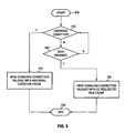
- Figure 9 is a flow chart of an exemplary UE monitoring whether or not to send a signaling connection release indication for various domains (e.g. PS or CS). The process starts in step 910.
- domains e.g. PS or CS
- the UE transitions to step 912 in which it checks to see whether an abnormal condition exists.
- an abnormal condition can include, for example, timer T3310, timer T3320, or timer T3340 expiring as described above. If these timers expire a certain predetermined number of times or if an explicit rejection is received based on the expiry of any of these timers, the UE proceeds to step 914 in which is sends a signaling connection release indication.
- the signaling connection release indication message is appended with a signaling release indication cause field.
- the signaling release indication cause field includes at least that the signaling release indication is based on an abnormal condition or state and a preferred embodiment includes the specific timer that timed out to result in the abnormal condition.
- step 920 it checks whether further data is expected at the UE. This can, as described above, include when an email is sent and confirmation of the sending of the email is received back at the UE. Other examples of where the UE will determine that no further data is expected would be known to those skilled in the art.
- step 920 the UE determines that the data transfer is finished (or in the case of a circuit switched domain that a call is finished) the UE proceeds to step 922 in which it sends a signaling connection release indication in which the signaling release indication cause field has been added and includes the fact that the UE requested an idle transition.
- step 920 if the data is not finished the UE loops back and continues to check whether an abnormal condition exists in step 912 and whether the data is finished in step 920.
- step 914 Once the signaling connection release indication is sent in step 914 or step 922, the process proceeds to step 930 and ends.
- the UE includes functional elements, implementable, for instance, by applications or algorithms carried out through operation of a UE microprocessor or by hardware implementation, that form a checker and a signaling connection release indication sender.
- the checker is configured to check whether a signaling connection release indication should be sent.
- a signaling connection release indication sender is configured to send a signaling connection release indication responsive to indication by the checker that the signaling connection release indication should be sent.
- the signaling connection release indication includes a signaling release indication cause field.
- the network is, instead, implicitly made aware of timing out of a timer, and the UE need not send a cause value indicating the timing out of the timer. That is to say, the timer starts timing upon authorization of the network.
- Cause codes are defined, and the cause codes are provided by the network to the UE. Such cause codes are used by the UE to initiate the timer.
- the network is implicitly aware of the reason for subsequent timing out of the timer as the cause code earlier sent by the network causes the timer to time. And, as a result, the UE need not send a cause value indicating the timing out of the timer.
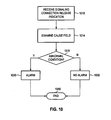
- step 1010 when a network element receives the signaling connection release indication in step 1010 the network element examines the signaling release indication cause field in step 1014 and in step 1016 checks whether the cause is an abnormal cause or whether it is due to the UE requesting an idle transition. If in step 1016 the signaling connection release indication is of abnormal cause, the network node proceeds to step 1020 in which an alarm is noted for performance monitoring and alarm monitoring purposes.
- the key performance indicator can be updated appropriately.
- step 1016 the cause of the signaling connection release indication is not a result of an abnormal condition, or in other words is a result of the UE requesting an idle transition
- the network node proceeds to step 1030 in which no alarm is raised and the indication can be filtered from the performance statistics, thereby preventing the performance statistics from being skewed.
- step 1040 the process ends.
- the reception and examination of the signaling release indication cause field results in initiation by the network element of an RRC connection release procedure. And, the packet switched connection data ends.
- step 1020 can be used to further distinguish between various alarm conditions.
- a T3310 time out could be used to keep a first set of statistics and a T3330 time out could be used to keep a second set of statistics.
- Step 1020 can distinguish between the causes of the abnormal condition, thereby allowing the network operator to track performance more efficiently.
- the network includes functional elements, implementable, for instance, by applications or algorithms carried out through operation of a processor or by hardware implementation, that form an examiner and an alarm generator.
- the examiner is configured to examine a signaling release indication cause field of the signaling connection release indication.
- the examiner checks whether the signaling release indication cause field indicates an abnormal condition.
- the alarm generator is configured selectably to generate an alarm if examination by the examiner determines the signal release indication cause field indicates the abnormal condition.
- the UTRAN upon reception of the signaling connection release indication, forwards the cause that is received and requests, from upper layers, for release of the signaling connection.
- the upper layers then are able to initiate the release of the signaling connection.
- the IE signaling release indication cause indicates the UE's upper layer cause to trigger the RRC of the UE to send the message.
- the cause is possibly the result of an abnormal upper layer procedure. Differentiation of the cause of the message is assured through successful reception of the IE.
- a possible scenario includes a scenario in which, prior to confirmation, by the RLC, of successful delivery of the signaling connection release indication message, reestablishment of the transmitting side of the RLC entity on the signaling radio bearer RB2 occurs.
- the UE retransmits the signaling connection release indication message, e.g., on the uplink DCCH using AM RLC on signaling radio bearer RB2.
- the UE aborts the signaling connection while in the new RAT.
- the connected mode state URA_PCH in some cases it may be more desirable to be in the connected mode state URA_PCH than in idle mode. For example, if the latency for connection to the CELL_DCH or the CELL_FACH connected mode states is required to be lower, it is preferable to be in a connected mode PCH state. There are two ways of accomplishing this. First is by changing the 3GPP specifications to allow for the UE to request the UTRAN move it to a specific state, in this case the URA_PCH state 128.
- the RRC connection manager may take into account other factors such as what state the RRC connection is currently in. If, for example, the RRC connection is in the URA_PCH state it may decide that it is unnecessary to move to idle mode 110 and thus no Signaling connection release procedure is initiated.
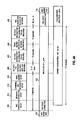
- Figure 4A shows a current UMTS implementation according to the infrastructure "four" example above. As illustrated in Figure 4 , time is across the horizontal axes.
- the UE starts in RRC idle state 110 and based on local data needing to be transmitted or a page received from the UTRAN, starts to establish an RRC connection.
- RRC connection setup 310 occurs first, and the RRC state is a connecting state 410 during this time.
- the RRC state is CELL_DCH state 122 during this.
- the time for moving from RRC idle to the time that the radio bearer is setup is approximately two seconds in this example.
- step 420 Data is next exchanged. In the example Figure 4A this is achieved in about two to four seconds and is illustrated by step 420.
- step 420 After data is exchanged in step 420, no data is being exchanged except for intermittent RLC signaling PDU as required and thus the radio bearer is reconfigured by the network to move into a lower data rate DCH state after approximately ten seconds. This is illustrated in steps 422 and 424.
- the RRC state proceeds to a disconnecting state 430 for approximately forty milliseconds, after which the UE is in a RRC idle state 110.
- the UE current consumption is illustrated for the period in which the RRC is in CELL_DCH state 122. As seen, the current consumption is approximately 200 to 300 milliamps for the entire duration of the CELL_DCH state. During disconnect and idle, about 3 milliamps are utilized, assuming a DRX cycle of 1.28 seconds. However, the 35 seconds of current consumption at 200 to 300 milliamps is draining on the battery.
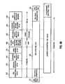
- Figure 4B utilizes the same exemplary infrastructure "four" from above, only now implementing the signalling connection release
- the UE in the example of Figure 4B has an application specific inactivity timeout, which in the example of Figure 4B is two seconds and is illustrated by step 440.
- the UE releases the signaling connection setup in step 442 and the RRC connection is released by the network in step 428.
- the current consumption during the CELL_DCH step 122 is still about 200 to 300 milliamps.
- the connection time is only about eight seconds.
- the considerably shorter amount of time that the mobile stays in the cell DCH state 122 results in significant battery savings for an always on UE device.
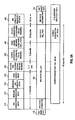
- Figure 5 shows a second example using the infrastructure indicated above as Infrastructure "three".
- Infrastructure three
- a connection setup occurs which takes approximately two seconds. This requires the RRC connection setup 310, the signaling connection setup 312, the ciphering and integrity setup 314 and the radio bearer setup 316.
- the UE moves from RRC idle mode 110 to a CELL_DCH state 122 with a RRC state connecting step 410 in between.
- RLC signaling PDU exchange receives no data and thus is idle for period of five seconds in step 422, except for intermittent RLC signaling PDU as required, at which point the radio bearer reconfigures the network to move into a CELL_FACH state 124 from CELL_DCH state 122. This is done in step 450.
- the RLC signaling PDU exchange finds that there is no data except for intermittent RLC signaling PDU as required for a predetermined amount of time, in this case thirty seconds, at which point a RRC connection release by network is performed in step 428.
- the current consumption during the DCH mode is between 200 and 300 milliamps.
- the current consumption lowers to approximately 120 to 180 milliamps.
- the power consumption is approximately 3 milliamps.
- the UTRA RRC Connected Mode state being CELL_DCH state 122 or CELL_FACH state 124 lasts for approximately forty seconds in the example of Figure 5A .
- Figure 5B illustrates the same infrastructure "three" as Figure 5A with the same connection time of about two seconds to get the RRC connection setup 310, signaling connection setup 312, ciphering integrity setup 314 and radio bearer setup 316. Further, RLC data PDU exchange 420 take approximately two to four seconds.
- a UE application detects a specific inactivity timeout in step 440, at which point the Signaling connection release indication procedure is initiated by the UE and as a consequence the RRC connection is released by the network in step 448.
- the RRC starts in a idle mode 110, moves to a CELL_DCH state 122 without proceeding into the CELL_FACH state.
- current consumption is approximately 200 to 300 milliamps in the time that the RRC stage is in CELL_DCH state 122 which according to the example of Figure 5 is approximate eight seconds.
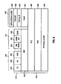
- Figure 6 illustrates a protocol stack for a UMTS network.
- the UMTS includes a CS control plane 610, PS control plane 611, and PS user plane 630
- NAS non-access stratum
- NAS portion 614 in CS control plane 610 includes a call control (CC) 618, supplementary services (SS) 620, and short message service (SMS) 622.
- CC call control
- SS supplementary services
- SMS short message service
- NAS portion 614 in PS control plane 611 includes both mobility management (MM) and GPRS mobility management (GMM) 626. It further includes SM/RABM 624 and GSMS 628.
- MM mobility management
- GMM GPRS mobility management
- CC 618 provides for call management signaling for circuit switched services.
- the session management portion of SM/RABM 624 provides for PDP context activation, deactivation and modification.
- SM/RABM 624 also provides for quality of service negotiation.
- the main function of the RABM portion of the SM/RABM 624 is to connect a PDP context to a Radio Access Bearer.
- SM/RABM 624 is responsible for the setup, modification and release of radio bearers.
- CS control plane 610 and PS control plane 611, in the access stratum 616 sit on radio resource control (RRC) 617.
- RRC radio resource control
- NAS portion 614 in PS user plane 630 includes an application layer 638, TCP/UDP layer 636, and PDP layer 634.
- PDP layer 634 can, for example, include internet protocol (IP).
- PS user plane 630 includes packet data convergence protocol (PDCP) 632.
- PDCP 632 is designed to make the WCDMA protocol suitable to carry TCP/IP protocol between UE and RNC (as seen in Figure 8 ), and is optionally for IP traffic stream protocol header compression and decompression.
- the UMTS Radio Link Control (RLC) 640 and Medium Access Control (MAC) layers 650 form the data link sub-layers of the UMTS radio interface and reside on the RNC node and the User Equipment.
- RLC Radio Link Control
- MAC Medium Access Control
- the Layer 1 (L1) UMTS layer (physical layer 650) is below the RLC/MAC layers 640 and 650. This layer is the physical layer for communications.
- UE 1100 is preferably a two-way wireless communication device having at least voice and data communication capabilities.
- UE 1100 preferably has the capability to communicate with other computer systems on the Internet.
- the wireless device may be referred to as a data messaging device, a two-way pager, a wireless e-mail device, a cellular telephone with data messaging capabilities, a wireless Internet appliance, or a data communication device, as examples.
- UE 1100 is enabled for two-way communication, it will incorporate a communication subsystem 1111, including both a receiver 1112 and a transmitter 1114, as well as associated components such as one or more, preferably embedded or internal, antenna elements 1116 and 1118, local oscillators (LOs) 1113, and a processing module such as a digital signal processor (DSP) 1120.
- LOs local oscillators
- DSP digital signal processor
- the particular design of the communication subsystem 1111 will be dependent upon the communication network in which the device is intended to operate.
- UE 1100 may include a communication subsystem 1111 designed to operate within the GPRS network or UMTS network.
- Network access requirements will also vary depending upon the type of network 1119.
- network access is associated with a subscriber or user of UE 1100.
- a GPRS mobile device therefore requires a subscriber identity module (SIM) card in order to operate on a GPRS network.
- SIM subscriber identity module
- UMTS a USIM or SIM module is required.
- CDMA a RUIM card or module is required.
- the UIM interface 1144 is normally similar to a card-slot into which a card can be inserted and ejected like a diskette or PCMCIA card.
- the UIM card can have approximately 64K of memory and hold many key configuration 1151, and other information 1153 such as identification, and subscriber related information.
- UE 1100 may send and receive communication signals over the network 1119.
- Signals received by antenna 1116 through communication network 1119 are input to receiver 1112, which may perform such common receiver functions as signal amplification, frequency down conversion, filtering, channel selection and the like, and in the example system shown in Figure 7 , analog to digital (A/D) conversion.
- A/D conversion of a received signal allows more complex communication functions such as demodulation and decoding to be performed in the DSP 1120.
- signals to be transmitted are processed, including modulation and encoding for example, by DSP 1120 and input to transmitter 1114 for digital to analog conversion, frequency up conversion, filtering, amplification and transmission over the communication network 1119 via antenna 1118.
- DSP 1120 not only processes communication signals, but also provides for receiver and transmitter control. For example, the gains applied to communication signals in receiver 1112 and transmitter 1114 maybe adaptively controlled through automatic gain control algorithms implemented in DSP 1120.
- Network 1119 may further communicate with multiple systems, including a server 1160 and other elements (not shown).
- network 1119 may communicate with both an enterprise system and a web client system in order to accommodate various clients with various service levels.
- UE 1100 preferably includes a microprocessor 1138 which controls the overall operation of the device. Communication functions, including at least data communications, are performed through communication subsystem 1111. Microprocessor 1138 also interacts with further device subsystems such as the display 1122, flash memory 1124, random access memory (RAM) 1126, auxiliary input/output (I/O) subsystems 1128, serial port 1130, keyboard 1132, speaker 1134, microphone 1136, a short-range communications subsystem 1140 and any other device subsystems generally designated as 1142.
- RAM random access memory
- I/O auxiliary input/output subsystems
- serial port 1130 keyboard 1132
- speaker 1134 speaker 1134
- microphone 1136 a short-range communications subsystem 1140 and any other device subsystems generally designated as 1142.
- Some of the subsystems shown in Figure 7 perform communication-related functions, whereas other subsystems may provide "resident" or on-device functions.
- some subsystems such as keyboard 1132 and display 1122, for example, may be used for both communication-related functions, such as entering a text message for transmission over a communication network, and device-resident functions such as a calculator or task list.
- Operating system software used by the microprocessor 1138 is preferably stored in a persistent store such as flash memory 1124, which may instead be a read-only memory (ROM) or similar storage element (not shown).
- ROM read-only memory
- Those skilled in the art will appreciate that the operating system, specific device applications, or parts thereof, may be temporarily loaded into a volatile memory such as RAM 1126. Received communication signals may also be stored in RAM 1126. Further, a unique identifier is also preferably stored in read-only memory.
- flash memory 1124 can be segregated into different areas for both computer programs 1158 and program data storage 1150, 1152, 1154 and 1156. These different storage types indicate that each program can allocate a portion of flash memory 1124 for their own data storage requirements.
- Microprocessor 1138 in addition to its operating system functions, preferably enables execution of software applications on the mobile device. A predetermined set of applications that control basic operations, including at least data and voice communication applications for example, will normally be installed on UE 1100 during manufacturing.
- a preferred software application may be a personal information manager (PIM) application having the ability to organize and manage data items relating to the user of the mobile device such as, but not limited to, e-mail, calendar events, voice mails, appointments, and task items.
- PIM personal information manager
- PIM application would preferably have the ability to send and receive data items, via the wireless network 1119.
- the PIM data items are seamlessly integrated, synchronized and updated, via the wireless network 1119, with the mobile device user's corresponding data items stored or associated with a host computer system.
- Further applications may also be loaded onto the mobile device 1100 through the network 1119, an auxiliary I/O subsystem 1128, serial port 1130, short-range communications subsystem 1140 or any other suitable subsystem 1142, and installed by a user in the RAM 1126 or preferably a non-volatile store (not shown) for execution by the microprocessor 1138.
- secure communication applications may enable electronic commerce functions and other such financial transactions to be performed using the UE 1100. These applications will however, according to the above, in many cases need to be approved by a carrier.
- a received signal such as a text message or web page download will be processed by the communication subsystem 1111 and input to the microprocessor 1138, which preferably further processes the received signal for output to the display 1122, or alternatively to an auxiliary I/O device 1128.
- a user of UE 1100 may also compose data items such as email messages for example, using the keyboard 1132, which is preferably a complete alphanumeric keyboard or telephone-type keypad, in conjunction with the display 1122 and possibly an auxiliary I/O device 1128. Such composed items may then be transmitted over a communication network through the communication subsystem 1111.
- UE 1100 For voice communications, overall operation of UE 1100 is similar, except that received signals would preferably be output to a speaker 1134 and signals for transmission would be generated by a microphone 1136.
- Alternative voice or audio I/O subsystems such as a voice message recording subsystem, may also be implemented on UE 1100.
- voice or audio signal output is preferably accomplished primarily through the speaker 1134, display 1122 may also be used to provide an indication of the identity of a calling party, the duration of a voice call, or other voice call related information for example.
- Serial port 1130 in Figure 7 would normally be implemented in a personal digital assistant (PDA)-type mobile device for which synchronization with a user's desktop computer (not shown) may be desirable.
- PDA personal digital assistant
- Such a port 1130 would enable a user to set preferences through an external device or software application and would extend the capabilities of mobile device 1100 by providing for information or software downloads to UE 1100 other than through a wireless communication network.
- the alternate download path may for example be used to load an encryption key onto the device through a direct and thus reliable and trusted connection to thereby enable secure device communication.
- serial port 1130 could be used for other communications, and could include as a universal serial bus (USB) port.
- USB universal serial bus
- An interface is associated with serial port 1130.
- Other communications subsystems 1140 such as a short-range communications subsystem, is a further optional component which may provide for communication between UE 1100 and different systems or devices, which need not necessarily be similar devices.
- the subsystem 1140 may include an infrared device and associated circuits and components or a BluetoothTM communication module to provide for communication with similarly enabled systems and devices.
- Figure 8 is a block diagram of a communication system 800 which includes a UE 802 which communicates through a wireless communication network.
- UE 802 communicates wirelessly with one of multiple Node Bs 806.
- Each Node B 806 is responsible for air interface processing and some radio resource management functions.
- Node B 806 provides functionality similar to a Base Transceiver Station in a GSM/GPRS networks.
- the wireless link shown in communication system 800 of Figure 8 represents one or more different channels, typically different radio frequency (RF) channels, and associated protocols used between the wireless network and UE 802.
- RF radio frequency
- a Uu air interface 804 is used between UE 802 and Node B 806.
- An RF channel is a limited resource that must be conserved, typically due to limits in overall bandwidth and a limited battery power of UE 802.
- a wireless network in actual practice may include hundreds of cells depending upon desired overall expanse of network coverage. All pertinent components may be connected by multiple switches and routers (not shown), controlled by multiple network controllers.
- Each Node B 806 communicates with a radio network controller (RNC) 810.
- RNC radio network controller
- the RNC 810 is responsible for control of the radio resources in its area.
- One RNC 810 control multiple Node Bs 806.
- the RNC 810 in UMTS networks provides functions equivalent to the Base Station Controller (BSC) functions in GSM/GPRS networks.
- BSC Base Station Controller
- an RNC 810 includes more intelligence including, for example, autonomous handovers management without involving MSCs and SGSNs.
- Node B 806 and RNC 810 The interface used between Node B 806 and RNC 810 is an Iub interface 808.
- An NBAP (Node B application part) signaling protocol is primarily used, as defined in 3GPP TS 25.433 V3.11.0 (2002-09) and 3GPP TS 25.433 V5.7.0 (2004-01).
- Universal Terrestrial Radio Access Network (UTRAN) 820 comprises the RNC 810, Node B 806 and the Uu air interface 804.
- MSC 830 Mobile Switching Centre
- PSTN Public Switching Centre
- Iu-CS interface 828 is the circuit-switched connection for carrying (typically) voice traffic and signaling between UTRAN 820 and the core voice network.
- the main signaling protocol used is RANAP (Radio Access Network Application Part).
- the RANAP protocol is used in UMTS signaling between the Core Network 821, which can be a MSC 830 or SSGN 850 (defined in more detail below) and UTRAN 820.
- RANAP protocol is defined in 3GPP TS 25.413 V3.11.1 (2002-09) and TS 25.413 V5.7.0 (2004-01).
- HLR home location registry
- UE 802 For all UEs 802 registered with a network operator, permanent data (such as UE 102 user's profile) as well as temporary data (such as UE's 802 current location) are stored in a home location registry (HLR) 838.
- HLR 838 In case of a voice call to UE 802, HLR 838 is queried to determine the current location of UE 802.
- a Visitor Location Register (VLR) 836 of MSC 830 is responsible for a group of location areas and stores the data of those mobile stations that are currently in its area of responsibility. This includes parts of the permanent mobile station data that have been transmitted from HLR 838 to the VLR 836 for faster access. However, the VLR 836 of MSC 830 may also assign and store local data, such as temporary identifications.
- UE 802 is also authenticated on system access by HLR 838.
- Packet data is routed through Service GPRS Support Node (SGSN) 850.
- SGSN 850 is the gateway between the RNC and the core network in a GPRS/UMTS network and is responsible for the delivery of data packets from and to the UEs within its geographical service area.
- Iu-PS interface 848 is used between the RNC 810 and SGSN 850, and is the packet-switched connection for carrying (typically) data traffic and signaling between the UTRAN 820 and the core data network.
- the main signaling protocol used is RANAP (described above).
- the SSGN 850 communicates with the Gateway GPRS Support Node (GGSN) 860.
- GGSN 860 is the interface between the UMTS/GPRS network and other networks such as the Internet or private networks.
- GGSN 860 is connected to a public data network PDN 870 over a Gi interface.
- wireless network may be connected to other systems, possibly including other networks, not explicitly shown in Figure 8 .
- a network will normally be transmitting at very least some sort of paging and system information on an ongoing basis, even if there is no actual packet data exchanged. Although the network consists of many parts, these parts all work together to result in certain behaviours at the wireless link.
Claims (45)
- Procédé destiné à traiter un message d'indication de libération d'une connexion de signalisation au niveau d'un équipement utilisateur (1100), le procédé étant caractérisé par le fait :de déterminer, au niveau de l'équipement utilisateur, qu'un message d'indication de libération d'une connexion de signalisation devrait être envoyé ;d'annexer, au niveau de l'équipement utilisateur, une cause au message d'indication de libération d'une connexion de signalisation si, au niveau de l'équipement utilisateur (1100), au moins l'un de : i) aucune donnée supplémentaire n'est attendue ; et ii) un appel est terminé ; etd'envoyer (922) le message d'indication de libération d'une connexion de signalisation avec la cause, si elle a été annexée, à un réseau sans fil.
- Procédé de la revendication 1, dans lequel la cause indique une demande par l'équipement utilisateur pour terminer une session de données PS.
- Procédé de la revendication 1, dans lequel la cause est établie à une fin de session de données PS demandée par le UE.
- Procédé de la revendication 1, dans lequel le fait d'envoyer le message d'indication de libération d'une connexion de signalisation comprend le fait de transmettre le message d'indication de libération d'une connexion de signalisation sur DCCH en utilisant AM RLC.
- Procédé de la revendication 1, dans lequel la cause indique une demande par l'équipement utilisateur (1100) pour une transition vers un état de repos ou un mode inactif.
- Procédé de la revendication 1, comprenant en plus le fait d'annexer, au niveau de l'équipement utilisateur, une cause de condition d'anormalité au message d'indication de libération d'une connexion de signalisation si, au niveau d'un équipement utilisateur (1100), une condition d'anormalité existe, et d'envoyer le message d'indication de libération d'une connexion de signalisation avec la cause de condition d'anormalité, si elle a été annexée, au réseau sans fil.
- Procédé de la revendication 1, dans lequel le fait de déterminer si un message d'indication de libération d'une connexion de signalisation devrait être envoyé comprend le fait de recevoir, au niveau de l'équipement utilisateur (1100) une demande pour libérer ou interrompre une connexion de signalisation d'une couche supérieure pour un domaine de réseau d'infrastructure CN spécifique.
- Procédé de la revendication 1, dans lequel le réseau sans fil est un réseau d'accès radio terrestre universel UTRAN.
- Procédé de la revendication 1, dans lequel la cause est un élément d'information, IE, du message d'indication de libération d'une connexion de signalisation.
- Procédé de la revendication 1, comprenant en plus le fait d'envoyer le message d'indication de libération d'une connexion de signalisation sans une cause si une minuterie de l'équipement utilisateur (1100) expire.
- Procédé de la revendication 1, dans lequel le message d'indication de libération d'une connexion de signalisation est envoyé avec la cause, si elle a été annexée, après qu'une minuterie d'équipement utilisateur expire.
- Procédé de la revendication 10, dans lequel la minuterie est sélectionnée dans le groupe constitué d'une minuterie d'échec d'attache, d'une minuterie de mise à jour de zone d'acheminement et d'une minuterie de demande de service GMM.
- Procédé destiné à traiter un message d'indication de libération d'une connexion de signalisation au niveau d'un réseau sans fil (1119), le procédé caractérisé par le fait :de recevoir (1010), d'un équipement utilisateur, un message d'indication de libération d'une connexion de signalisation auquel une cause est annexée si au moins l'un(e) i) d'aucune idée supplémentaire n'est attendue ; et ii) d'un appel est terminé ;de déterminer si le message d'indication de libération d'une connexion de signalisation est un résultat d'une condition de normalité ou d'anormalité sur la base de la cause d'indication de libération d'une connexion de signalisation reçue, si elle a été annexée au message d'indication de libération d'une connexion de signalisation ; etd'initier une transition d'état pour une connexion de signalisation si le message d'indication de libération d'une connexion de signalisation est un résultat d'une condition de normalité.
- Procédé de la revendication 13, dans lequel les étapes de réception, de détermination et d'initiation sont mises en oeuvre dans un réseau d'accès radio terrestre universel UTRAN.
- Procédé de la revendication 13, dans lequel la cause indique une demande par l'équipement utilisateur (1100) pour terminer une session de données PS.
- Procédé de la revendication 13, dans lequel la cause est établie à une fin de session de données PS demandée par le UE.
- Procédé de la revendication 13, dans lequel la cause indique une demande par l'équipement utilisateur (1100) pour une transition vers un état de repos ou un mode inactif.
- Procédé de la revendication 13, dans lequel la cause est un élément d'information, IE, du message d'indication de libération d'une connexion de signalisation.
- Procédé de la revendication 13, comprenant en plus le fait de recevoir un message d'indication de libération d'une connexion de signalisation sans une cause si une minuterie d'équipement utilisateur (1100) expire.
- Procédé de la revendication 13, dans lequel le message d'indication de libération d'une connexion de signalisation est reçu dans la cause, si elle a été annexée, après qu'une minuterie d'équipement utilisateur expire.
- Procédé de la revendication 19, dans lequel la minuterie est sélectionnée du groupe constitué d'une minuterie d'échec d'attache, d'une minuterie de mise à jour de zone d'acheminement et d'une minuterie de demande de service GMM.
- Procédé de la revendication 13, comprenant en plus le fait de recevoir, de l'équipement utilisateur, un message d'indication de libération d'une connexion de signalisation auquel une cause de condition d'anormalité est annexée si, au niveau de l'équipement utilisateur, une condition d'anormalité existe.
- Equipement utilisateur (1100) adapté pour traiter un message d'indication de libération d'une connexion de signalisation, l'équipement utilisateur ayant un sous-système radio (1111) ; un processeur adapté pour interagir avec une mémoire (1124 ; 1126), le sous-système radio (1111) et une interface utilisateur, l'équipement utilisateur étant caractérisé par des moyens :pour déterminer (912) qu'un message d'indication de libération d'une connexion de signalisation devrait être envoyé ;pour annexer une cause au message d'indication de libération d'une connexion de signalisation si au moins l'un(e) i) d'aucune idée supplémentaire n'est attendue ; et ii) d'un appel est terminé ; etpour envoyer (922) le message d'indication de libération d'une connexion de signalisation avec la cause, si elle a été annexée, à un réseau sans fil.
- Equipement utilisateur (1100) de la revendication 23, dans lequel la cause indique une demande par l'équipement utilisateur pour terminer une session de données PS.
- Equipement utilisateur (1100) de la revendication 23, dans lequel la cause est établie à une fin de session de données PS demandée par le UE.
- Equipement utilisateur (1100) de la revendication 23, dans lequel le fait d'envoyer le message d'indication de libération d'une connexion de signalisation comprend le fait de transmettre le message d'indication de libération d'une connexion de signalisation sur DCCH en utilisant AM RLC.
- Equipement utilisateur (1100) de la revendication 23, dans lequel la cause indique une demande pour une transition vers un état de repos ou un mode inactif.
- Equipement utilisateur (1100) de la revendication 23, caractérisé en plus par un moyen pour annexer une cause de condition d'anormalité au message d'indication de libération d'une connexion de signalisation si, au niveau de l'équipement utilisateur, une condition d'anormalité existe, et un moyen pour envoyer le message d'indication de libération d'une connexion de signalisation avec la cause de condition d'anormalité, si elle a été annexée, au réseau sans fil.
- Equipement utilisateur (1100) de la revendication 23, dans lequel le moyen pour déterminer (912) qu'un message d'indication de libération d'une connexion de signalisation devrait être envoyé comprend un moyen pour recevoir une demande pour libérer ou interrompre une connexion de signalisation d'une couche supérieure pour un domaine de réseau d'infrastructure spécifique CN.
- Equipement utilisateur (1100) de la revendication 23, dans lequel le réseau sans fil est un réseau d'accès radio terrestre universel UTRAN.
- Equipement utilisateur (1100) de la revendication 23, dans lequel la cause est un élément d'information IE du message d'indication de libération d'une connexion de signalisation.
- Equipement utilisateur (1100) de la revendication 23 caractérisé en plus par un moyen pour envoyer le message d'indication de libération d'une connexion de signalisation sans une cause si une minuterie d'équipement utilisateur expire.
- Equipement utilisateur (1100) de la revendication 23 caractérisé en plus par un moyen pour envoyer le message d'indication de libération d'une connexion de signalisation avec la cause, si elle a été annexée, après qu'une minuterie d'équipement utilisateur expire.
- Equipement utilisateur (1100) de la revendication 32, dans lequel ladite minuterie est sélectionnée dans le groupe constitué : d'une minuterie d'échec d'attache, d'une minuterie de mise à jour d'acheminement, et d'une minuterie de demande de service GMM.
- Appareil de réseau sans fil (1119) destiné à traiter un message d'indication de libération d'une connexion de signalisation, ledit appareil de réseau (1119) étant caractérisé par des moyens :pour recevoir (1010), d'un équipement utilisateur, un message d'indication de libération d'une connexion de signalisation auquel une cause est annexée si au moins l'un(e) i) d'aucune idée supplémentaire n'est attendue ; et ii) d'un appel est terminé ;pour déterminer si le message d'indication de libération d'une connexion de signalisation est un résultat d'une condition de normalité ou d'anormalité sur la base de la cause d'indication de libération d'une connexion de signalisation reçue, si elle a été annexée au message d'indication de libération d'une connexion de signalisation ; etpour initier une transition d'état pour une connexion de signalisation si le message d'indication de libération d'une connexion de signalisation est un résultat d'une condition de normalité.
- Appareil de réseau sans fil (1119) de la revendication 35, dans lequel les moyens de réception, de détermination et d'initiation sont mises en oeuvre dans un réseau d'accès radio terrestre universel UTRAN.
- Appareil de réseau sans fil (1119) de la revendication 35, dans lequel la cause indique une demande par l'équipement utilisateur pour terminer une session de données PS.
- Appareil de réseau sans fil (1119) de la revendication 35, dans lequel la cause est établie à la fin de session de données PS demandée par le UE.
- Appareil de réseau sans fil (1119) de la revendication 35, dans lequel la cause, si elle a été annexée au message d'indication de libération d'une connexion de signalisation, indique une demande par l'équipement utilisateur pour une transition vers un état de repos ou un mode inactif.
- Appareil de réseau sans fil (1119) de la revendication 35, dans lequel la cause est un élément d'information IE du message d'indication de libération d'une connexion de signalisation.
- Appareil de réseau sans fil (1119) de la revendication 35, caractérisé en plus par un moyen pour recevoir le message d'indication de libération d'une connexion de signalisation sans une cause si une minuterie d'équipement utilisateur expire.
- Appareil de réseau sans fil (1119) de la revendication 35, dans lequel le message d'indication de libération d'une connexion de signalisation est reçu avec la cause, si elle a été annexée, après qu'une minuterie d'équipement utilisateur expire.
- Appareil de réseau sans fil (1119) de la revendication 41, dans lequel la minuterie est sélectionnée du groupe constitué d'une minuterie d'échec d'attache, d'une minuterie de mise à jour de zone d'acheminement et d'une minuterie de demande de service GMM.
- Appareil de réseau sans fil (1119) de la revendication 35, comprenant en plus un moyen pour recevoir, de l'équipement utilisateur, un message d'indication de libération d'une connexion de signalisation auquel une cause de condition d'anormalité est annexée si, au niveau de l'équipement utilisateur, une condition d'anormalité existe.
- Appareil de réseau sans fil de la revendication 35, caractérisé en plus par un moyen pour recevoir le message d'indication de libération d'une connexion de signalisation après expiration d'une minuterie d'équipement utilisateur.
Priority Applications (15)
| Application Number | Priority Date | Filing Date | Title |
|---|---|---|---|
| EP10174218.7A EP2363981B1 (fr) | 2006-05-17 | 2006-08-14 | Procédé et système pour signaler la cause de déconnexion dans un réseau UMTS |
| CN201310421418.5A CN103619071B (zh) | 2006-05-17 | 2007-05-16 | 用于umts网络中的信令释放原因指示的方法和系统 |
| SG2013036116A SG190647A1 (en) | 2006-05-17 | 2007-05-16 | Method and system for signaling release cause indication in a umts network |
| AU2007202206A AU2007202206C1 (en) | 2006-05-17 | 2007-05-16 | Method and system for signaling release cause indication in a UMTS network |
| BRPI0705715A BRPI0705715B1 (pt) | 2006-05-17 | 2007-05-16 | método e sistema para sinalização de indicação de causa de liberação em uma rede de umts |
| CN2007101379068A CN101080102B (zh) | 2006-05-17 | 2007-05-16 | 用于umts网络中的信令释放原因指示的方法和系统 |
| SG200907608-4A SG157398A1 (en) | 2006-05-17 | 2007-05-16 | Method and system for signaling release cause indication in a umts network |
| SG200703551-2A SG137794A1 (en) | 2006-05-17 | 2007-05-16 | Method and system for signaling release cause indication in a umts network |
| CA2589373A CA2589373C (fr) | 2006-05-17 | 2007-05-16 | Methode et systeme pemettant de traiter les indications de cause des autorisations de signalisation dans un reseau de systeme universel de telecommunications mobiles (umts) |
| JP2007131146A JP4777300B2 (ja) | 2006-05-17 | 2007-05-17 | Umtsネットワークで解放理由指示を信号伝達する方法およびシステム |
| TW096117599A TWI491234B (zh) | 2006-05-17 | 2007-05-17 | 通信行動電信系統網路中用於訊號釋出原因指示之方法及裝置 |
| KR1020070048255A KR101107357B1 (ko) | 2006-05-17 | 2007-05-17 | Umts 네트워크에서 시그널링 해제 지시 원인을처리하는 방법 및 시스템 |
| AU2010202720A AU2010202720B2 (en) | 2006-05-17 | 2010-06-29 | Method and system for signaling release cause indication in a UMTS network |
| JP2011083176A JP5183764B2 (ja) | 2006-05-17 | 2011-04-04 | Umtsネットワークで解放理由指示を信号伝達する方法およびシステム |
| JP2012263015A JP5386030B2 (ja) | 2006-05-17 | 2012-11-30 | Umtsネットワークで解放理由指示を信号伝達する方法およびシステム |
Applications Claiming Priority (1)
| Application Number | Priority Date | Filing Date | Title |
|---|---|---|---|
| US74746606P | 2006-05-17 | 2006-05-17 |
Related Child Applications (2)
| Application Number | Title | Priority Date | Filing Date |
|---|---|---|---|
| EP10174218.7A Division EP2363981B1 (fr) | 2006-05-17 | 2006-08-14 | Procédé et système pour signaler la cause de déconnexion dans un réseau UMTS |
| EP10174218.7 Division-Into | 2010-08-26 |
Publications (2)
| Publication Number | Publication Date |
|---|---|
| EP1858209A1 EP1858209A1 (fr) | 2007-11-21 |
| EP1858209B1 true EP1858209B1 (fr) | 2010-10-13 |
Family
ID=37026599
Family Applications (2)
| Application Number | Title | Priority Date | Filing Date |
|---|---|---|---|
| EP06118909A Active EP1858209B1 (fr) | 2006-05-17 | 2006-08-14 | Procédé et système pour indiquer la cause de déconnexion d'une connection de signalisation dans un réseau UMTS |
| EP10174218.7A Active EP2363981B1 (fr) | 2006-05-17 | 2006-08-14 | Procédé et système pour signaler la cause de déconnexion dans un réseau UMTS |
Family Applications After (1)
| Application Number | Title | Priority Date | Filing Date |
|---|---|---|---|
| EP10174218.7A Active EP2363981B1 (fr) | 2006-05-17 | 2006-08-14 | Procédé et système pour signaler la cause de déconnexion dans un réseau UMTS |
Country Status (11)
| Country | Link |
|---|---|
| US (5) | US8644829B2 (fr) |
| EP (2) | EP1858209B1 (fr) |
| JP (2) | JP5183764B2 (fr) |
| CN (2) | CN101080102B (fr) |
| AT (1) | ATE484937T1 (fr) |
| AU (1) | AU2010202720B2 (fr) |
| DE (1) | DE602006017517D1 (fr) |
| ES (1) | ES2353609T3 (fr) |
| HK (1) | HK1109973A1 (fr) |
| SG (2) | SG190647A1 (fr) |
| TW (1) | TWI491234B (fr) |
Cited By (6)
| Publication number | Priority date | Publication date | Assignee | Title |
|---|---|---|---|---|
| US8885607B2 (en) | 2007-11-13 | 2014-11-11 | Blackberry Limited | Method and apparatus for state/mode transitioning |
| US8983532B2 (en) | 2009-12-30 | 2015-03-17 | Blackberry Limited | Method and system for a wireless communication device to adopt varied functionalities based on different communication systems by specific protocol messages |
| US9049657B2 (en) | 2011-11-11 | 2015-06-02 | Blackberry Limited | System and method of user equipment state transition |
| US9119208B2 (en) | 2009-11-23 | 2015-08-25 | Blackberry Limited | Method and apparatus for state/mode transitioning |
| US9125208B2 (en) | 2008-11-10 | 2015-09-01 | Blackberry Limited | Method and apparatus of transition to a battery efficient state or configuration by indicating end of data transmission in long term evolution |
| US9226271B2 (en) | 2009-11-23 | 2015-12-29 | Blackberry Limited | Method and apparatus for state/mode transitioning |
Families Citing this family (47)
| Publication number | Priority date | Publication date | Assignee | Title |
|---|---|---|---|---|
| US7949377B2 (en) | 2005-12-14 | 2011-05-24 | Research In Motion Limited | Method and apparatus for user equipment directed radio resource control in a UMTS network |
| US8265034B2 (en) * | 2006-05-17 | 2012-09-11 | Research In Motion Limited | Method and system for a signaling connection release indication |
| ATE484937T1 (de) | 2006-05-17 | 2010-10-15 | Research In Motion Ltd | Verfahren und system zur anzeige einer ursache für einen abbau einer signalisierungsverbindung in einem umts netz |
| US20080049662A1 (en) * | 2006-08-25 | 2008-02-28 | Research In Motion Limited | Apparatus, and associated method, for releasing a data-service radio resource allocated to a data-service-capable mobile node |
| US8433316B2 (en) * | 2006-11-03 | 2013-04-30 | Qualcomm Incorporated | Efficient search for wireless networks in connected mode |
| KR101381475B1 (ko) * | 2007-04-13 | 2014-04-04 | 삼성전자주식회사 | 유저 단말기의 무선 자원 제어 상태를 아이들 상태로천이하는 방법 및 이를 위한 시스템 및 그 단말기 |
| GB0714927D0 (en) * | 2007-08-01 | 2007-09-12 | Nokia Siemens Networks Oy | Resource allocation |
| US8693409B2 (en) * | 2007-08-10 | 2014-04-08 | Interdigital Patent Holdings, Inc. | Method and apparatus for supporting paging over an HS-DSCH in CELL—PCH and URA—PCH states |
| EP2271168A1 (fr) * | 2007-08-20 | 2011-01-05 | Research In Motion Limited | Procédé et système pour indiquer le relâchement de connexion de signalisation |
| US20090209291A1 (en) * | 2008-02-19 | 2009-08-20 | Motorola Inc | Wireless communication device and method with expedited connection release |
| EP2258076B1 (fr) * | 2008-03-25 | 2012-01-11 | Telefonaktiebolaget L M Ericsson (publ) | Architecture de commande de règles de conduite et de facturation |
| US8515436B2 (en) * | 2008-03-27 | 2013-08-20 | Qualcomm Incorporated | Management of wireless connections |
| US8737294B2 (en) * | 2008-08-11 | 2014-05-27 | Via Telecom Co., Ltd. | Apparatus and method for handling RLC retransmission failure according to activation status of security mode |
| WO2010079591A1 (fr) * | 2009-01-07 | 2010-07-15 | 富士通株式会社 | Station de base sans fil, terminal, système de communication sans fil, et procédé de communication sans fil |
| US8797949B2 (en) | 2009-05-22 | 2014-08-05 | Qualcomm Incorporated | Announcing a communication session within a wireless communications system |
| CN101990191A (zh) * | 2009-07-31 | 2011-03-23 | 中兴通讯股份有限公司 | 一种判断无线资源控制连接请求归属域的方法及系统 |
| CN102006635A (zh) * | 2009-09-02 | 2011-04-06 | 中兴通讯股份有限公司 | 数据传输方法及系统 |
| EP2505036B1 (fr) | 2009-11-23 | 2018-08-22 | BlackBerry Limited | Procédé et appareil pour transition d'état ou de mode |
| KR20120096546A (ko) * | 2009-11-24 | 2012-08-30 | 리서치 인 모션 리미티드 | 상태/모드 전이를 위한 방법 및 장치 |
| US8688826B2 (en) * | 2009-11-30 | 2014-04-01 | Motorola Mobility Llc | Mobile computing device and method with intelligent pushing management |
| US8155625B2 (en) * | 2009-12-22 | 2012-04-10 | Motorola Mobility, Inc. | Methods and apparatus for conserving energy used by a mobile device |
| CN102111795A (zh) * | 2009-12-24 | 2011-06-29 | 中兴通讯股份有限公司 | 一种用于确定异常呼叫原因的信令的提取方法及装置 |
| CN102783221A (zh) * | 2010-01-12 | 2012-11-14 | 诺基亚西门子通信公司 | 用于指示网络单元的功率节约模式的设备和方法 |
| US8780744B2 (en) | 2010-01-25 | 2014-07-15 | Qualcomm Incorporated | Selective allocation of dedicated channel (DCH) resources within a wireless communications system |
| US20110194433A1 (en) * | 2010-02-05 | 2011-08-11 | Qualcomm Incorporated | Managing dedicated channel resource allocation to user equipment based on radio bearer traffic within a wireless communications system |
| JP5053409B2 (ja) * | 2010-04-15 | 2012-10-17 | 株式会社エヌ・ティ・ティ・ドコモ | 移動通信システム、制御装置及び制御方法 |
| US8743763B2 (en) * | 2010-07-23 | 2014-06-03 | Qualcomm Incorporated | User device dormancy |
| CN102469446B (zh) | 2010-11-19 | 2014-08-20 | 华为技术有限公司 | 一种业务处理的方法和装置 |
| US20130114571A1 (en) * | 2011-11-07 | 2013-05-09 | Qualcomm Incorporated | Coordinated forward link blanking and power boosting for flexible bandwidth systems |
| US8885517B2 (en) | 2012-02-16 | 2014-11-11 | Giri Prassad Deivasigamani | Operational state mismatch identification for a mobile device |
| KR20130108750A (ko) * | 2012-03-26 | 2013-10-07 | 삼성전자주식회사 | 통신시스템에서 다중 무선 접속 베어러 서비스를 제공하기 위한 장치 및 방법 |
| CN102711254B (zh) * | 2012-04-16 | 2014-10-22 | 中国联合网络通信集团有限公司 | 网络侧的资源释放控制方法及rnc |
| CN103517454A (zh) * | 2012-06-27 | 2014-01-15 | 联发科技股份有限公司 | 增强信令连接释放指示处理方法 |
| JP5318259B1 (ja) * | 2012-07-05 | 2013-10-16 | ソフトバンクモバイル株式会社 | 端末装置及びその接続方法 |
| US9693306B2 (en) * | 2012-07-11 | 2017-06-27 | Blackberry Limited | Mechanisms to support UE power preference signaling |
| CN103716912B (zh) * | 2012-10-09 | 2017-10-20 | 电信科学技术研究院 | 一种释放无线资源控制连接的方法、装置及系统 |
| CN105793828B (zh) | 2013-12-26 | 2019-06-21 | 英特尔公司 | 具有pci快速增强的系统和方法 |
| US9513392B2 (en) | 2014-02-18 | 2016-12-06 | Pgs Geophysical As | Estimation of direct arrival signals based on predicted direct arrival signals and measurements |
| US9814090B2 (en) | 2014-03-12 | 2017-11-07 | Mediatek Inc. | Maintaining a packet-switched signaling connection during handover between cells |
| US11088937B1 (en) * | 2014-05-08 | 2021-08-10 | Google Llc | System and method for synchronized route update |
| CN106455130A (zh) * | 2015-08-12 | 2017-02-22 | 深圳市中兴微电子技术有限公司 | 资源释放的方法、用户设备、接入网设备及系统 |
| CN107645738A (zh) * | 2016-07-22 | 2018-01-30 | 中兴通讯股份有限公司 | 一种无线资源的释放方法及装置 |
| JP6994040B2 (ja) | 2017-02-03 | 2022-01-14 | 華為技術有限公司 | 接続解放方法及び装置 |
| US10341927B2 (en) * | 2017-07-20 | 2019-07-02 | GM Global Technology Operations LLC | Vehicle wireless unit and method of operating the same |
| US10959286B2 (en) * | 2018-09-20 | 2021-03-23 | Samsung Electronics Co., Ltd. | Methods and systems for managing circuit-switched (CS) signaling connection release in mobile communications |
| US10833975B2 (en) * | 2018-11-02 | 2020-11-10 | Cisco Technology, Inc. | Operations processing of multiple-protocol packets by packet switching devices in a network |
| US20210337481A1 (en) * | 2020-04-23 | 2021-10-28 | Qualcomm Incorporated | Application information aided fast dormancy |
Family Cites Families (216)
| Publication number | Priority date | Publication date | Assignee | Title |
|---|---|---|---|---|
| SE469736B (sv) * | 1992-02-05 | 1993-08-30 | Ericsson Telefon Ab L M | Felhantering i radiolaenkar |
| JP3532921B2 (ja) * | 1993-09-03 | 2004-05-31 | テレフオンアクチーボラゲツト エル エム エリクソン | 移動局に補助サービスを提供する方法とシステム |
| JP3161910B2 (ja) | 1994-07-26 | 2001-04-25 | シャープ株式会社 | 通信装置 |
| CA2223781C (fr) | 1995-06-14 | 2002-05-21 | International Business Machines Corporation | Transmission de donnees par paquets dans les systemes de communication a acces multiple par difference de code |
| JPH0955764A (ja) | 1995-08-14 | 1997-02-25 | Nippon Telegr & Teleph Corp <Ntt> | 無線パケット通信方法 |
| FI103454B (fi) * | 1996-04-01 | 1999-06-30 | Nokia Telecommunications Oy | Matkaviestimen toimintatilojen ohjaus pakettiradiojärjestelmässä |
| US5812636A (en) * | 1996-09-06 | 1998-09-22 | Northern Telecom Limited | System and method for faulty mobile unit isolation |
| US6018521A (en) * | 1996-12-27 | 2000-01-25 | Motorola, Inc. | Network interface subsystem for use in an ATM communications system |
| US6249681B1 (en) * | 1997-04-01 | 2001-06-19 | Nokia Mobile Phones Ltd. | Method and apparatus for packet data call re-establishment in a telecommunications system |
| KR100232881B1 (ko) | 1997-10-08 | 1999-12-01 | 윤종용 | 리시버 전원제어방법과 그에 따른 무선호출 수신기 |
| JPH11313370A (ja) | 1998-04-28 | 1999-11-09 | Toshiba Corp | 移動パケット通信システムとそのデータ通信装置、基地局装置及び移動端末装置 |
| JPH11331947A (ja) * | 1998-05-18 | 1999-11-30 | Nippon Telegr & Teleph Corp <Ntt> | 無線局と無線データ通信方法とプログラムの記憶媒体 |
| US6064340A (en) | 1998-07-02 | 2000-05-16 | Intersil Corporation | Electrostatic discharge locating apparatus and method |
| KR20000014143A (ko) | 1998-08-14 | 2000-03-06 | 서평원 | 통신시스템에서파일럿수신감도측정메시지의개선된전송방법 |
| FI108203B (fi) | 1998-11-27 | 2001-11-30 | Nokia Mobile Phones Ltd | Menetelmä ja järjestely tiedon siirtämiseksi pakettiradiopalvelussa |
| US6223044B1 (en) | 1998-12-18 | 2001-04-24 | Telefonaktiebolaget Lm Ericsson | Adaptive location level |
| DE69932452T2 (de) | 1999-01-04 | 2007-02-22 | Telefonaktiebolaget Lm Ericsson (Publ) | Verhandlung von trägerdiensten |
| US6275712B1 (en) | 1999-02-26 | 2001-08-14 | Nokia Mobile Phones Ltd | Mobile station control states based on available power |
| EP1033846A1 (fr) | 1999-03-01 | 2000-09-06 | Alcatel | Procédé pour contrôler la transmission de données en paquets dans le sens montant dans un système de communication sans fil |
| US6377790B1 (en) * | 1999-03-08 | 2002-04-23 | Sharp Laboratories Of America, Inc. | Mobile-initiated, packet switched communications method |
| US6965778B1 (en) * | 1999-04-08 | 2005-11-15 | Ipr Licensing, Inc. | Maintenance of channel usage in a wireless communication system |
| ATE540482T1 (de) | 1999-04-12 | 2012-01-15 | Samsung Electronics Co Ltd | Verfahren zum regeln einer geschalteten übertragung eines zugeordneten kanals in w-cdma nachrichtenübertragungssystem |
| SE522068C2 (sv) | 1999-07-15 | 2004-01-13 | Ericsson Telefon Ab L M | Metod och anordning för att åstadkomma radioaccessbärartjänster |
| GB9913092D0 (en) | 1999-06-04 | 1999-08-04 | Nokia Telecommunications Oy | A network element |
| FI107674B (fi) | 1999-08-30 | 2001-09-14 | Nokia Mobile Phones Ltd | Menetelmä tiedonsiirron optimoimiseksi pakettikytkentäisessä langattomassa tiedonsiirtojärjestelmässä |
| JP2001074820A (ja) | 1999-09-06 | 2001-03-23 | Hitachi Ltd | 基板電圧検出回路及びこれを用いた基板雑音検出回路 |
| US6657984B1 (en) | 1999-10-29 | 2003-12-02 | Samsung Electronics, Co., Ltd. | System and method providing backward compatibility of radio link protocols in a wireless network |
| US6654360B1 (en) * | 2000-01-10 | 2003-11-25 | Qualcomm Incorporated | Method and system for providing dormant mode wireless packet data services |
| US6593850B1 (en) | 2000-01-27 | 2003-07-15 | Pittway Corp. | Wireless intrusion detector with test mode |
| US7054268B1 (en) | 2000-02-04 | 2006-05-30 | Nokia Mobile Phones, Inc. | Method and arrangement for transferring information in a packet radio service with application-based choice of release mode |
| FI110651B (fi) | 2000-02-22 | 2003-02-28 | Nokia Corp | Menetelmä siirretyn datan määrän tarkastamiseksi |
| FI110352B (fi) | 2000-02-24 | 2002-12-31 | Nokia Corp | Menetelmä ja järjestely yhteyksien uudelleenmuodostamisen optimoimiseksi solukkoradiojärjestelmässä, joka tukee reaaliaikaista ja ei-reaaliaikaista tiedonsiirtoa |
| US7466741B2 (en) * | 2000-03-03 | 2008-12-16 | Qualcomm Incorporated | Method and apparatus for concurrently processing multiple calls in a spread spectrum communications system |
| FI20000700A (fi) | 2000-03-24 | 2001-09-25 | Nokia Mobile Phones Ltd | Parannetun tehonsäästöominaisuuden omaava matkapuhelin |
| EP1139613A1 (fr) | 2000-03-31 | 2001-10-04 | Telefonaktiebolaget L M Ericsson (Publ) | Terminal d'abonné, contrôleur de réseau et système de transmission pour exécuter le transfert de paquets de données avec un retard réduit |
| FI109437B (fi) | 2000-04-03 | 2002-07-31 | Nokia Corp | Resurssien varaus pakettimuotoisessa tiedonsiirrossa |
| WO2001099313A1 (fr) | 2000-06-22 | 2001-12-27 | Samsung Electronics Co., Ltd | Appareil pour la transmission a declenchement periodique d'un signal de voie de commande physique specialisee et procede correspondant mis en oeuvre dans un systeme de communication mobile |
| US6748246B1 (en) | 2000-07-05 | 2004-06-08 | Telefonaktiebolaget Lm Ericsson (Publ) | Method and apparatus for selecting an access technology in a multi-mode terminal |
| US7230932B2 (en) | 2000-08-18 | 2007-06-12 | Nokia Mobile Phones Ltd. | Method and apparatus for discontinuous reception scheme and power saving mode for user equipment in packet access mode |
| FI109628B (fi) | 2000-08-21 | 2002-09-13 | Nokia Corp | Menetelmä langattoman päätelaitteen tehonkulutuksen pienentämiseksi, tiedonsiirtojärjestelmä ja langaton päätelaite |
| JP3405331B2 (ja) | 2000-08-22 | 2003-05-12 | ニチハ株式会社 | 留め付け金具及び外壁施工構造 |
| US6690655B1 (en) | 2000-10-19 | 2004-02-10 | Motorola, Inc. | Low-powered communication system and method of operation |
| US7225238B1 (en) * | 2000-10-25 | 2007-05-29 | Cisco Technology, Inc. | Method and system for providing services for wireless data calls |
| US6845236B2 (en) | 2000-11-01 | 2005-01-18 | Lg Electronics Inc. | Method for concurrent multiple services in a mobile communication system |
| FI111423B (fi) * | 2000-11-28 | 2003-07-15 | Nokia Corp | Järjestelmä kanavanvaihdon jälkeen tapahtuvan tietoliikenteen salauksen varmistamiseksi |
| US6970438B2 (en) | 2001-02-16 | 2005-11-29 | Nokia Mobile Phones Ltd. | Method and device for downlink packet switching |
| US7089002B2 (en) * | 2001-05-11 | 2006-08-08 | Telefonaktiebolaget Lm Ericsson (Publ) | Releasing plural radio connections with omnibus release message |
| US7046992B2 (en) | 2001-05-11 | 2006-05-16 | Telefonaktiebolaget Lm Ericsson (Publ) | Authentication of termination messages in telecommunications system |
| JP4015428B2 (ja) * | 2001-05-16 | 2007-11-28 | 株式会社日立コミュニケーションテクノロジー | インアクティビティタイマを備えた無線基地局/無線基地局制御装置、無線端末及び状態制御方法 |
| US6654630B2 (en) * | 2001-05-31 | 2003-11-25 | Infraredx, Inc. | Apparatus and method for the optical imaging of tissue samples |
| FI113144B (fi) * | 2001-07-12 | 2004-02-27 | Nokia Corp | Pakettidatapalvelun tarjoaminen langattomassa tietoliikennejärjestelmässä |
| US7337019B2 (en) | 2001-07-16 | 2008-02-26 | Applied Materials, Inc. | Integration of fault detection with run-to-run control |
| US7221670B2 (en) | 2001-08-13 | 2007-05-22 | Motorola, Inc. | Apparatus and method for supplying information concerning packet data to a base station |
| JP4039851B2 (ja) | 2001-12-07 | 2008-01-30 | 株式会社エヌ・ティ・ティ・ドコモ | 移動通信端末、アプリケーションプログラムの実行状態制御方法、アプリケーションプログラム、及びアプリケーションプログラムを記録した記録 |
| US7609673B2 (en) | 2002-02-08 | 2009-10-27 | Telefonaktiebolaget Lm Ericsson (Publ) | Packet-based conversational service for a multimedia session in a mobile communications system |
| US20030134662A1 (en) * | 2001-12-28 | 2003-07-17 | Samsung Electronics Co., Ltd. | Clear reject message for call clearing and mobile resource assignment with holding call |
| KR100765123B1 (ko) * | 2002-02-16 | 2007-10-11 | 엘지전자 주식회사 | Srns 재할당 방법 |
| DE60314331T2 (de) | 2002-05-03 | 2008-02-14 | Innovative Sonic Ltd., Road Town | Verfahren von Zellenaktualisierung via Leerlauf zwecks Stromsparung in einem UMTS Mobil nach gescheiterter Funkverbindung. |
| US7054630B2 (en) | 2002-05-13 | 2006-05-30 | Qualcomm Incorporated | Selective processing of the common control channel |
| WO2003105519A1 (fr) | 2002-06-05 | 2003-12-18 | 株式会社エヌ・ティ・ティ・ドコモ | Serveur, systeme de communication mobile, procede de gestion d'informations de position, station fixe radio, station mobile, procede d'appel dans un systeme de communication mobile et procede de communication mobile |
| US7068636B2 (en) | 2002-06-21 | 2006-06-27 | Asustek Computer Inc. | Method for determining RLC entity re-establishment during SRNS relocation |
| JP4197408B2 (ja) | 2002-06-26 | 2008-12-17 | パナソニック株式会社 | 通信システム、端末装置及び通信システムの中継局選択方法 |
| US20040192312A1 (en) | 2002-07-16 | 2004-09-30 | Jia-Ru Li | Communication system for voice and data with wireless TCP server |
| US6961570B2 (en) | 2002-07-17 | 2005-11-01 | Asustek Computer Inc. | Handling of a wireless device re-entering a service area |
| US7152111B2 (en) | 2002-08-15 | 2006-12-19 | Digi International Inc. | Method and apparatus for a client connection manager |
| KR100510651B1 (ko) | 2002-09-12 | 2005-08-31 | 엘지전자 주식회사 | 이동통신 시스템의 자원 관리 방법 |
| US7277392B2 (en) | 2002-10-01 | 2007-10-02 | Motorola, Inc. | Method and apparatus for managing the usage of data link resources |
| US7606190B2 (en) | 2002-10-18 | 2009-10-20 | Kineto Wireless, Inc. | Apparatus and messages for interworking between unlicensed access network and GPRS network for data services |
| KR100822120B1 (ko) * | 2002-10-18 | 2008-04-14 | 키네토 와이어리즈 인코포레이션 | 비인가 무선 통신 시스템을 이용한 인가 무선 통신시스템의 커버리지 영역 확장 장치 및 방법 |
| DE60234541D1 (de) | 2002-10-23 | 2010-01-07 | Nokia Corp | Funkbetriebsmittelsteuerverfahren in einem mobilkommunikationssystem und mobilkommunikaitonssystem |
| US7437172B2 (en) * | 2002-12-10 | 2008-10-14 | Qualcomm Incorporated | Discontinuous transmission (DTX) detection in wireless communication systems |
| KR100658650B1 (ko) | 2002-12-12 | 2006-12-15 | 후아웨이 테크놀러지 컴퍼니 리미티드 | 무선 근거리 통신망과 사용자 단말기간의 서비스 접속에대한 처리 방법 |
| ATE408318T1 (de) | 2002-12-16 | 2008-09-15 | Research In Motion Ltd | Verfahren und vorrichtung zur senkung des energieverbrauches in einem cdma- kommunikationsgerät |
| SE0300047D0 (sv) * | 2003-01-08 | 2003-01-08 | Ericsson Telefon Ab L M | MBMS in UTRAN |
| US7423993B2 (en) | 2003-02-10 | 2008-09-09 | Nokia Corporation | Connection release in communication network |
| US6822973B2 (en) | 2003-02-18 | 2004-11-23 | Motorola, Inc. | Apparatus and method for implementing a reduced slotted mode in a communication system |
| US7720960B2 (en) | 2003-03-04 | 2010-05-18 | Cisco Technology, Inc. | Method and apparatus providing prepaid billing for network services using explicit service authorization in an access server |
| US7787413B2 (en) | 2003-03-14 | 2010-08-31 | Nortel Networks Limited | Method for mobile station request release of multiple packet data service sessions simultaneously using resource release request messages |
| JP4350565B2 (ja) | 2003-03-27 | 2009-10-21 | キヤノン株式会社 | 情報処理装置および方法 |
| FR2854756B1 (fr) * | 2003-05-07 | 2005-08-12 | Evolium Sas | Procede pour l'etablissement de connexion dans un systeme de radiocommunications mobiles |
| CA2428236A1 (fr) * | 2003-05-08 | 2004-11-08 | M-Stack Limited | Appareil et methode de traitement des messages de connexion de commande des ressources radio du reseau universel d'acces radio de terre dans un equipement d'utilisateur du systemeuniversel de telecommunications mobiles |
| EP1638221A4 (fr) | 2003-06-20 | 2009-12-09 | Fujitsu Ltd | Systeme de communication mobile wcdma |
| US7406314B2 (en) * | 2003-07-11 | 2008-07-29 | Interdigital Technology Corporation | Wireless transmit receive unit having a transition state for transitioning from monitoring to duplex connected states and method |
| CN100482483C (zh) | 2003-07-28 | 2009-04-29 | 麦格纳国际公司 | 框架一体化的后悬架系统 |
| KR20050014984A (ko) | 2003-08-01 | 2005-02-21 | 삼성전자주식회사 | 멀티미디어 브로드캐스트/멀티캐스드 서비스를 제공하는이동통신시스템에서 무선 자원 연결을 요청하는 메시지를재전송하는 방법 |
| US20050032555A1 (en) | 2003-08-07 | 2005-02-10 | Iqbal Jami | Method of intermittent activation of receiving circuitry of a mobile user terminal |
| US7512101B2 (en) | 2003-08-15 | 2009-03-31 | Samsung Electronics Co., Ltd. | Apparatus and method for enabling different reduced slot cycle modes in a wireless network |
| KR100548393B1 (ko) | 2003-08-20 | 2006-02-02 | 엘지전자 주식회사 | 이동통신 단말기의 패킷 서비스 성능 향상 방법 |
| TWI245513B (en) | 2003-08-26 | 2005-12-11 | Ind Tech Res Inst | Method and apparatus for controlling multi-radio access |
| US7130668B2 (en) | 2003-09-01 | 2006-10-31 | Samsung Electronics Co., Ltd. | Method and system for controlling sleep mode in broadband wireless access communication system |
| US7634554B2 (en) | 2003-09-18 | 2009-12-15 | Cisco Technology, Inc. | TTL exploration technique for determining capabilities and configuration of a peer router |
| GB0322741D0 (en) * | 2003-09-29 | 2003-10-29 | Nortel Networks Ltd | Structured probable causes for management systems and network devices and their exploitation |
| GB0323246D0 (en) | 2003-10-03 | 2003-11-05 | Fujitsu Ltd | Virtually centralized uplink scheduling |
| JP4327800B2 (ja) | 2003-10-16 | 2009-09-09 | テレフオンアクチーボラゲット エル エム エリクソン(パブル) | Wlanアクセス・ポイントとサービス提供ネットワークとの間のゲートウェイ・ノードを使用する、wlanアクセス・ポイントを介したcdma/umtsサービスへのアクセス |
| EP1530395A2 (fr) | 2003-11-07 | 2005-05-11 | Lg Electronics Inc. | Technique de téléappel pour supporter les transmissions de données point à multipoint (P-T-M). |
| US7623530B2 (en) | 2003-11-20 | 2009-11-24 | Nokia Corporation | Indication of service flow termination by network control to policy decision function |
| JP2005175831A (ja) | 2003-12-10 | 2005-06-30 | Ntt Docomo Inc | 通信端末およびプログラム |
| FI20031911A0 (fi) | 2003-12-29 | 2003-12-29 | Nokia Corp | Menetelmä ja järjestelmä access-verkkopalvelun kontrolloimiseksi reaaliaikaisessa datapalvelussa |
| FI20031912A0 (fi) | 2003-12-29 | 2003-12-29 | Nokia Corp | Menetelmä ja järjestelmä reaaliaikaisen tiedonsiirtopalvelun kontrolloimiseksi |
| US20050149940A1 (en) | 2003-12-31 | 2005-07-07 | Sychron Inc. | System Providing Methodology for Policy-Based Resource Allocation |
| US20050143056A1 (en) | 2003-12-31 | 2005-06-30 | Iyer Prakash R. | Method and apparatus for providing push-to-talk services in a cellular communication system |
| KR100664278B1 (ko) | 2004-01-09 | 2007-01-04 | 엘지전자 주식회사 | Mbms 무선통신 시스템 |
| DE602004006594T2 (de) | 2004-01-09 | 2008-01-31 | M-Stack Ltd. | Gerät und Verfahren zur Implementierung der Erfassung von Systeminformationsänderungen in universellen mobilen Telekommunikationssystemen |
| US7440459B2 (en) | 2004-02-02 | 2008-10-21 | Lucent Technologies Inc. | Methods of detecting protocol support in wireless communication systems |
| US7480267B2 (en) | 2004-02-06 | 2009-01-20 | M-Stack Limited | Apparatus and method for operating a communications device in a mobile communications network |
| US7519035B2 (en) | 2004-02-23 | 2009-04-14 | Sharp Laboratories Of America, Inc. | Method to negotiate consumed power versus medium occupancy time in MIMO based WLAN systems using admission control |
| US8483140B1 (en) | 2004-03-05 | 2013-07-09 | AT&T Mobiity II LLC | Intelligent uplink resource release control in a mobile station |
| GB0406664D0 (en) | 2004-03-24 | 2004-04-28 | Samsung Electronics Co Ltd | Mobile communications |
| US7636331B2 (en) | 2004-04-19 | 2009-12-22 | Lg Electronic Inc. | Transmission of control information in wireless communication system |
| KR100703487B1 (ko) | 2004-04-21 | 2007-04-03 | 삼성전자주식회사 | Umts 시스템에서 효율적인 패킷 데이터 서비스 운용방법 |
| US20050245267A1 (en) | 2004-04-30 | 2005-11-03 | Guethaus Roland J | Methods of allocating a channel to baseband processing units in a communication system |
| EP1596616A1 (fr) * | 2004-05-14 | 2005-11-16 | Research In Motion Limited | Procédé et dispositif permetant de liberer rapidement les ressources d'un réseau pour une station mobile sur la base des conditions de perte des signaux et d'affaiblissement de batterie |
| US20050265350A1 (en) | 2004-05-28 | 2005-12-01 | Murali Narasimha | Concurrent packet data session set-up for push-to-talk over cellular |
| US7580388B2 (en) * | 2004-06-01 | 2009-08-25 | Lg Electronics Inc. | Method and apparatus for providing enhanced messages on common control channel in wireless communication system |
| US7181215B2 (en) | 2004-06-02 | 2007-02-20 | Sony Ericsson Mobile Communications Ab | Automatic GPRS/EDGE re-attach |
| US8855572B2 (en) | 2004-06-16 | 2014-10-07 | Qualcomm Incorporated | Method and apparatus for link control in wireless communications |
| KR100605625B1 (ko) | 2004-06-17 | 2006-07-31 | 엘지전자 주식회사 | 유엠티에스시스템의 세션해제방법 |
| US7089012B2 (en) * | 2004-07-29 | 2006-08-08 | Motorola, Inc. | Method and system for use in reducing cost associated with lost connections in wireless communication |
| EP1775977A4 (fr) | 2004-08-05 | 2011-04-06 | Mitsubishi Electric Corp | Station de base, appareil de terminal de communication mobile, et procédé de sélection de cellule primaire |
| US7529354B2 (en) * | 2004-08-10 | 2009-05-05 | Nokia Corporation | Method of managing a connection release, corresponding system and device |
| US8254921B2 (en) | 2004-08-12 | 2012-08-28 | Qualcomm Incorporated | Default configurations with differential encoding in a wireless communication system |
| KR101000682B1 (ko) | 2004-08-13 | 2010-12-10 | 엘지전자 주식회사 | 이동통신시스템에서의 rrc연결 설정방법 |
| BRPI0511645A (pt) | 2004-08-13 | 2008-01-02 | Lg Electronics Inc | estabelecimento de conexão de controle de recursos de rádio em sistema de comunicação sem fios |
| JP2008512751A (ja) | 2004-09-03 | 2008-04-24 | テネシー、パシフィック、グループ、エル、エル、シー | デジタル著作権ライセンシングの集中管理 |
| US7904094B2 (en) * | 2004-10-27 | 2011-03-08 | Motorola Mobility, Inc. | Method for reducing wireless communication procedure failure |
| US20060094478A1 (en) | 2004-11-04 | 2006-05-04 | Lg Electronics Inc. | Mobile power handling method and apparatus |
| US8379553B2 (en) | 2004-11-22 | 2013-02-19 | Qualcomm Incorporated | Method and apparatus for mitigating the impact of receiving unsolicited IP packets at a wireless device |
| US20060176167A1 (en) * | 2005-01-25 | 2006-08-10 | Laser Shield Systems, Inc. | Apparatus, system, and method for alarm systems |
| US8620314B2 (en) * | 2005-03-10 | 2013-12-31 | Qualcomm Incorporated | Apparatus and methods for determining connection quality of a wireless device on a wireless communications network |
| JP4577505B2 (ja) * | 2005-03-31 | 2010-11-10 | 日本電気株式会社 | 移動体通信システムにおけるダウンリンクrrcメッセージと移動機のセル間移動との競合救済方法 |
| US7925290B2 (en) | 2005-03-31 | 2011-04-12 | Qualcomm Incorporated | System and method for efficiently providing high-performance dispatch services in a wireless system |
| US7283819B2 (en) | 2005-04-25 | 2007-10-16 | Research In Motion Limited | Method and apparatus for CDMA timer-based registration on a mobile device |
| US8488453B2 (en) | 2005-05-18 | 2013-07-16 | Koninklijke Philips Electronics N.V. | Method and apparatus for enhanced uplink data transmission |
| WO2006134480A2 (fr) | 2005-06-15 | 2006-12-21 | Spyder Navigations L.L.C. | Signalisation par rrc de modification rapide de cellule desservant hs-dsch |
| US20060293067A1 (en) | 2005-06-27 | 2006-12-28 | Leung Kin K | Method and apparatus for controlling sleep intervals of a mobile unit |
| DE202005021930U1 (de) | 2005-08-01 | 2011-08-08 | Corning Cable Systems Llc | Faseroptische Auskoppelkabel und vorverbundene Baugruppen mit Toning-Teilen |
| JP4767626B2 (ja) | 2005-08-24 | 2011-09-07 | ドコモ・テクノロジ株式会社 | 移動局、無線アクセスネットワーク装置および移動交換局並びに通信サービスアクセス方法 |
| WO2007023366A2 (fr) | 2005-08-24 | 2007-03-01 | Nokia Corporation | Dispositif, procede et progiciel permettant de configurer un protocole de liaison radio pour un flux de donnees ip (protocole internet) |
| US8094595B2 (en) * | 2005-08-26 | 2012-01-10 | Qualcomm Incorporated | Method and apparatus for packet communications in wireless systems |
| US7643838B2 (en) | 2005-09-29 | 2010-01-05 | Motorola, Inc. | Integrity protection count synchronization method |
| US7894375B2 (en) | 2005-10-31 | 2011-02-22 | Research In Motion Limited | Method, and associated apparatus, for transitioning communications of hybrid access terminal between communication systems |
| US7761097B2 (en) | 2005-10-31 | 2010-07-20 | Research In Motion Limited | Apparatus, and associated method, for permitting communication system transition based upon signal threshold determination |
| US7720482B2 (en) | 2005-10-31 | 2010-05-18 | Research In Motion Limited | Method and apparatus for transitioning between EVDO and CDMA 1X systems using redundant data call blockings |
| US7768962B2 (en) | 2005-11-01 | 2010-08-03 | Nokia Corporation | HSUPA HARQ process flushing |
| CN101300757B (zh) | 2005-11-04 | 2017-08-11 | 日本电气株式会社 | 无线电通信系统及用于其的发送功率控制方法 |
| US7949377B2 (en) | 2005-12-14 | 2011-05-24 | Research In Motion Limited | Method and apparatus for user equipment directed radio resource control in a UMTS network |
| CN101341673A (zh) | 2005-12-19 | 2009-01-07 | Lg电子株式会社 | 读取动态系统信息块的方法 |
| ES2417929T3 (es) | 2005-12-22 | 2013-08-09 | Electronics And Telecommunications Research Institute | Método para una operación de transmisión/recepción discontinua para reducir el consumo de energía en un sistema celular |
| US7353120B2 (en) | 2006-01-24 | 2008-04-01 | Research In Motion Limited | Electrostatic discharge monitoring and manufacturing process control system |
| DE102006004250B4 (de) | 2006-01-30 | 2008-04-24 | Infineon Technologies Ag | Kommunikationseinrichtung, Verfahren zum Betreiben einer Kommunkationseinrichtung und Computerprogrammelement |
| JP2007214711A (ja) | 2006-02-08 | 2007-08-23 | Nec Corp | 移動通信システム、移動端末装置、無線ネットワーク制御装置及びそれらに用いる状態遷移トリガ設定方法 |
| WO2007097670A1 (fr) | 2006-02-27 | 2007-08-30 | Telefonaktiebolaget L M Ericsson (Publ) | Procédé et appareil de communication |
| CN100531128C (zh) * | 2006-02-28 | 2009-08-19 | 华为技术有限公司 | 业务网关、服务系统、服务质量协商及服务资源释放方法 |
| KR100846282B1 (ko) | 2006-03-10 | 2008-07-16 | (주)케이티에프테크놀로지스 | 이동통신 단말기의 보존 모드 진입 방법 |
| CN101411095B (zh) | 2006-03-28 | 2013-06-19 | 三星电子株式会社 | 用于移动通信系统中的连接终端的非连续接收的方法和设备 |
| US7410875B2 (en) * | 2006-04-06 | 2008-08-12 | United Microelectronics Corp. | Semiconductor structure and fabrication thereof |
| WO2007123351A1 (fr) | 2006-04-25 | 2007-11-01 | Samsung Electronics Co., Ltd. | Procédé et appareil pour l'établissement d'une connexion radio dans un système de communication mobile |
| US9614648B2 (en) | 2006-04-29 | 2017-04-04 | Philips Lighting Holding B.V. | Method and apparatus for controlling energy expanding of sensor network nodes |
| US8265034B2 (en) | 2006-05-17 | 2012-09-11 | Research In Motion Limited | Method and system for a signaling connection release indication |
| ATE484937T1 (de) | 2006-05-17 | 2010-10-15 | Research In Motion Ltd | Verfahren und system zur anzeige einer ursache für einen abbau einer signalisierungsverbindung in einem umts netz |
| AU2007202206C1 (en) | 2006-05-17 | 2011-02-10 | Blackberry Limited | Method and system for signaling release cause indication in a UMTS network |
| ATE481792T1 (de) | 2006-05-18 | 2010-10-15 | Huawei Tech Co Ltd | Verfahren und system zur verwendung eines ue im ersatzmodus beim ausloggen aus einem netzwerk |
| CN100499869C (zh) | 2006-05-24 | 2009-06-10 | 华为技术有限公司 | 一种终端设备接入方法及系统 |
| EP1860424B1 (fr) | 2006-05-26 | 2011-08-17 | NanoWorld AG | Sonde à balayage à alignement automatique pour microscope à balayage |
| US7852817B2 (en) | 2006-07-14 | 2010-12-14 | Kineto Wireless, Inc. | Generic access to the Iu interface |
| US20080039086A1 (en) | 2006-07-14 | 2008-02-14 | Gallagher Michael D | Generic Access to the Iu Interface |
| CN101114988B (zh) | 2006-07-24 | 2010-12-29 | 中兴通讯股份有限公司 | 基于非连续发射预测自适应多速率业务的流控算法 |
| EP1892895A1 (fr) | 2006-08-25 | 2008-02-27 | Research In Motion Limited | Appareil et procédé associé permettant de libérer une ressource radio pour service de données allouée à un noeud mobile capable de recevoir un tel service |
| US20080049662A1 (en) | 2006-08-25 | 2008-02-28 | Research In Motion Limited | Apparatus, and associated method, for releasing a data-service radio resource allocated to a data-service-capable mobile node |
| US8630604B2 (en) | 2006-11-17 | 2014-01-14 | Industrial Technology Research Institute | Communication methods and devices for dual-mode communication systems |
| US8311046B2 (en) | 2006-11-28 | 2012-11-13 | Core Wireless Licensing S.A.R.L. | Method for the delivery of messages in a communication system |
| JP2008141252A (ja) | 2006-11-29 | 2008-06-19 | Sharp Corp | 通信機器、通信方法、通信回路、通信システム、プログラム、およびプログラムを記録したコンピュータ読み取り可能な記録媒体 |
| US8515478B2 (en) | 2006-12-18 | 2013-08-20 | Qualcomm Incorporated | Fast state transition for a UE with reconfiguration over paging |
| BRPI0808664A2 (pt) | 2007-03-06 | 2014-08-26 | Ntt Docomo Inc | Estação móvel, estação base, sistema de comunicação de rádio e método de controle de comunicação |
| US20080232310A1 (en) | 2007-03-19 | 2008-09-25 | Shugong Xu | Flexible user equipment-specified discontinuous reception |
| KR101381475B1 (ko) | 2007-04-13 | 2014-04-04 | 삼성전자주식회사 | 유저 단말기의 무선 자원 제어 상태를 아이들 상태로천이하는 방법 및 이를 위한 시스템 및 그 단말기 |
| KR20140081906A (ko) | 2007-04-30 | 2014-07-01 | 인터디지탈 테크날러지 코포레이션 | 강화된 cell_fach 상태로부터의 셀 재선택 및 천이와 강화된 cell_fach 상태로의 셀 재선택 및 천이 처리 |
| US20080304510A1 (en) | 2007-06-08 | 2008-12-11 | Hai Qu | Method and apparatus for controlling radio connection based on inputs from applications |
| US9887813B2 (en) | 2007-06-13 | 2018-02-06 | Qualcomm Incorporated | Protocol data unit recovery |
| US7925233B2 (en) | 2007-07-20 | 2011-04-12 | Htc Corporation | Methods for handling measurement reports in a wireless communication system |
| US20090028084A1 (en) | 2007-07-25 | 2009-01-29 | High Tech Computer, Corp. | Method for reducing user equipment power consumption under a communication network |
| WO2009022840A2 (fr) | 2007-08-10 | 2009-02-19 | Lg Electronics Inc. | Procédé d'établissement de canal dans un système de communication sans fil |
| EP2271168A1 (fr) | 2007-08-20 | 2011-01-05 | Research In Motion Limited | Procédé et système pour indiquer le relâchement de connexion de signalisation |
| KR100937432B1 (ko) | 2007-09-13 | 2010-01-18 | 엘지전자 주식회사 | 무선 통신 시스템에서의 무선자원 할당 방법 |
| KR101370909B1 (ko) | 2007-10-01 | 2014-03-19 | 엘지전자 주식회사 | 핸드오버시 신속한 상향 데이터 전송방법 |
| KR101487557B1 (ko) | 2007-10-23 | 2015-01-29 | 엘지전자 주식회사 | 공통제어채널의 데이터를 전송하는 방법 |
| ES2390936T3 (es) | 2007-11-02 | 2012-11-19 | Telefonaktiebolaget Lm Ericsson (Publ) | Métodos y aparatos para procesar mensajes de control de error en un sistema de comunicación inalámbrico |
| EP2061192B1 (fr) | 2007-11-13 | 2012-04-11 | Research In Motion Limited | Procédé et appareil pour la transition d'état/de mode |
| CN101453742B (zh) | 2007-12-04 | 2010-09-08 | 大唐移动通信设备有限公司 | 一种小区更新方法、设备及系统 |
| TW201021488A (en) | 2007-12-07 | 2010-06-01 | Interdigital Patent Holdings | Method and apparatus for supporting configuration and control of the RLC and PDCP sub-layers |
| CA2708604C (fr) | 2007-12-10 | 2017-01-31 | Interdigital Patent Holdings, Inc. | Procede et appareil de declenchement d'un abandon de paquet de controle de radioliaison et d'un retablissement de controle de radioliaison |
| CA2852143C (fr) | 2007-12-20 | 2015-04-14 | Telefonaktiebolaget L M Ericsson (Publ) | Liberation de ressources radio de canal commun specialise ameliore (e-dch) |
| TW200931868A (en) | 2008-01-04 | 2009-07-16 | Interdigital Patent Holdings | Method and apparatus for performing an enhanced random access channel procedure in a Cell_FACH state |
| EP2243323A1 (fr) | 2008-02-22 | 2010-10-27 | Nokia Corporation | Détection autonome d'équipement mobile à déclenchement rapide |
| US20090221277A1 (en) | 2008-02-29 | 2009-09-03 | Palm, Inc. | Disconnection techniques in wireless communications networks |
| RU2457636C2 (ru) | 2008-03-21 | 2012-07-27 | Интердиджитал Пэйтент Холдингз, Инк. | Способ и устройство для выполнения изменения обслуживающей соты hs-dsch |
| GB2461159B (en) | 2008-06-18 | 2012-01-04 | Lg Electronics Inc | Method for transmitting Mac PDUs |
| US8824305B2 (en) | 2008-07-09 | 2014-09-02 | Qualcomm Incorporated | Paging schemes for local network access |
| US8737294B2 (en) | 2008-08-11 | 2014-05-27 | Via Telecom Co., Ltd. | Apparatus and method for handling RLC retransmission failure according to activation status of security mode |
| JP5233504B2 (ja) | 2008-08-25 | 2013-07-10 | 富士通株式会社 | 経路制御装置およびパケット廃棄方法 |
| US9094910B2 (en) | 2008-09-09 | 2015-07-28 | Htc Corporation | Methods utilized in mobile device for handling situations when time alignment timer expires, and mobile device thereof |
| US8391239B2 (en) | 2008-09-22 | 2013-03-05 | Qualcomm Incorporated | Bearer count alignment during inter-rat handover |
| BRPI0921356B1 (pt) | 2008-11-10 | 2020-10-13 | Blackberry Limited | método para enviar uma indicação de dormência rápida e equipamento de usuário |
| CN102365837B (zh) | 2009-03-29 | 2014-05-14 | Lg电子株式会社 | 在无线通信系统中发送控制信息的方法及其装置 |
| US8902827B2 (en) | 2009-04-21 | 2014-12-02 | Htc Corporation | Relay for handling data forwarding in a wireless communication system and related method for controlling the same |
| US8638711B2 (en) | 2009-08-11 | 2014-01-28 | Qualcomm Incorporated | Systems and methods of maintaining core network status during serving radio network subsystem relocation |
| EP2505036B1 (fr) | 2009-11-23 | 2018-08-22 | BlackBerry Limited | Procédé et appareil pour transition d'état ou de mode |
| WO2011060997A1 (fr) | 2009-11-23 | 2011-05-26 | Research In Motion Limited | Procédé et appareil assurant des transitions d'état et de mode |
| MX2012005868A (es) | 2009-11-23 | 2012-11-30 | Research In Motion Ltd | Activacion de transicion de estado o modo basada en transmision de mensajes de sri. |
| KR20120096546A (ko) | 2009-11-24 | 2012-08-30 | 리서치 인 모션 리미티드 | 상태/모드 전이를 위한 방법 및 장치 |
| EP2341687B1 (fr) | 2009-12-30 | 2016-03-23 | BlackBerry Limited | Procédé et système pour permettre une fonctionnalité variée basée sur des transmissions multiples |
| US8983532B2 (en) | 2009-12-30 | 2015-03-17 | Blackberry Limited | Method and system for a wireless communication device to adopt varied functionalities based on different communication systems by specific protocol messages |
| CA2781509A1 (fr) | 2010-02-10 | 2011-08-18 | Research In Motion Limited | Procede et appareil de transition d'etat/mode |
| US8594747B2 (en) | 2011-05-06 | 2013-11-26 | Apple Inc. | Adaptive fast dormancy in a mobile device |
| US9049657B2 (en) | 2011-11-11 | 2015-06-02 | Blackberry Limited | System and method of user equipment state transition |
| US8787225B2 (en) | 2012-07-11 | 2014-07-22 | Blackberry Limited | Phase-rotated reference signals for multiple antennas |
-
2006
- 2006-08-14 AT AT06118909T patent/ATE484937T1/de not_active IP Right Cessation
- 2006-08-14 US US11/464,380 patent/US8644829B2/en active Active
- 2006-08-14 ES ES06118909T patent/ES2353609T3/es active Active
- 2006-08-14 DE DE602006017517T patent/DE602006017517D1/de active Active
- 2006-08-14 EP EP06118909A patent/EP1858209B1/fr active Active
- 2006-08-14 EP EP10174218.7A patent/EP2363981B1/fr active Active
-
2007
- 2007-05-16 SG SG2013036116A patent/SG190647A1/en unknown
- 2007-05-16 CN CN2007101379068A patent/CN101080102B/zh active Active
- 2007-05-16 CN CN201310421418.5A patent/CN103619071B/zh active Active
- 2007-05-16 SG SG200907608-4A patent/SG157398A1/en unknown
- 2007-05-17 TW TW096117599A patent/TWI491234B/zh active
-
2008
- 2008-04-15 HK HK08104258.1A patent/HK1109973A1/xx unknown
-
2010
- 2010-06-29 AU AU2010202720A patent/AU2010202720B2/en active Active
-
2011
- 2011-04-04 JP JP2011083176A patent/JP5183764B2/ja active Active
-
2012
- 2012-11-30 JP JP2012263015A patent/JP5386030B2/ja active Active
-
2014
- 2014-02-03 US US14/171,320 patent/US10582562B2/en active Active
-
2017
- 2017-08-04 US US15/669,254 patent/US11197342B2/en active Active
-
2019
- 2019-10-22 US US16/660,668 patent/US11147121B2/en active Active
-
2021
- 2021-09-14 US US17/474,997 patent/US20210410224A1/en active Pending
Cited By (13)
| Publication number | Priority date | Publication date | Assignee | Title |
|---|---|---|---|---|
| US8885607B2 (en) | 2007-11-13 | 2014-11-11 | Blackberry Limited | Method and apparatus for state/mode transitioning |
| US9456436B2 (en) | 2007-11-13 | 2016-09-27 | Blackberry Limited | Method and apparatus for state/mode transitioning |
| US9019877B2 (en) | 2007-11-13 | 2015-04-28 | Blackberry Limited | Method and apparatus for state/mode transitioning |
| US9026153B2 (en) | 2007-11-13 | 2015-05-05 | Blackberry Limited | Method and apparatus for state/mode transitioning |
| US9037167B2 (en) | 2007-11-13 | 2015-05-19 | Blackberry Limited | Method and apparatus for state/mode transitioning |
| US9125208B2 (en) | 2008-11-10 | 2015-09-01 | Blackberry Limited | Method and apparatus of transition to a battery efficient state or configuration by indicating end of data transmission in long term evolution |
| US9119208B2 (en) | 2009-11-23 | 2015-08-25 | Blackberry Limited | Method and apparatus for state/mode transitioning |
| US9144104B2 (en) | 2009-11-23 | 2015-09-22 | Blackberry Limited | Method and apparatus for state/mode transitioning |
| US9226271B2 (en) | 2009-11-23 | 2015-12-29 | Blackberry Limited | Method and apparatus for state/mode transitioning |
| US9467976B2 (en) | 2009-11-23 | 2016-10-11 | Blackberry Limited | Method and apparatus for state/mode transitioning |
| US9521657B2 (en) | 2009-11-23 | 2016-12-13 | Blackberry Limited | Method and apparatus for state/mode transitioning |
| US8983532B2 (en) | 2009-12-30 | 2015-03-17 | Blackberry Limited | Method and system for a wireless communication device to adopt varied functionalities based on different communication systems by specific protocol messages |
| US9049657B2 (en) | 2011-11-11 | 2015-06-02 | Blackberry Limited | System and method of user equipment state transition |
Also Published As
| Publication number | Publication date |
|---|---|
| US20210410224A1 (en) | 2021-12-30 |
| JP2011176856A (ja) | 2011-09-08 |
| EP2363981B1 (fr) | 2017-08-02 |
| EP2363981A1 (fr) | 2011-09-07 |
| HK1109973A1 (en) | 2008-06-27 |
| CN101080102B (zh) | 2013-10-09 |
| JP2013066222A (ja) | 2013-04-11 |
| US11197342B2 (en) | 2021-12-07 |
| AU2010202720A1 (en) | 2010-07-15 |
| SG157398A1 (en) | 2009-12-29 |
| US10582562B2 (en) | 2020-03-03 |
| JP5183764B2 (ja) | 2013-04-17 |
| JP5386030B2 (ja) | 2014-01-15 |
| ATE484937T1 (de) | 2010-10-15 |
| TWI491234B (zh) | 2015-07-01 |
| US8644829B2 (en) | 2014-02-04 |
| US20070270140A1 (en) | 2007-11-22 |
| US20140194131A1 (en) | 2014-07-10 |
| EP1858209A1 (fr) | 2007-11-21 |
| ES2353609T3 (es) | 2011-03-03 |
| CN101080102A (zh) | 2007-11-28 |
| US11147121B2 (en) | 2021-10-12 |
| US20200128611A1 (en) | 2020-04-23 |
| DE602006017517D1 (de) | 2010-11-25 |
| AU2010202720B2 (en) | 2012-04-26 |
| CN103619071A (zh) | 2014-03-05 |
| TW200816763A (en) | 2008-04-01 |
| US20180014348A1 (en) | 2018-01-11 |
| CN103619071B (zh) | 2017-08-08 |
| SG190647A1 (en) | 2013-06-28 |
Similar Documents
| Publication | Publication Date | Title |
|---|---|---|
| US11147121B2 (en) | Method and system for signaling release cause indication in a UMTS network | |
| US8265034B2 (en) | Method and system for a signaling connection release indication | |
| CA2589373C (fr) | Methode et systeme pemettant de traiter les indications de cause des autorisations de signalisation dans un reseau de systeme universel de telecommunications mobiles (umts) | |
| EP2028909B1 (fr) | Procédé et système pour signaler une indication de relâchement de connexion | |
| EP2247146B1 (fr) | Procédé et appareil pour la gestion des ressources radio à partir d'un équipement d'abonné dans un réseau UMTS | |
| US9037167B2 (en) | Method and apparatus for state/mode transitioning | |
| CA2661592C (fr) | Appareil, et procede associe, destines a distribuer des ressources radio de service de donnees attribuees a un noeud mobile offrant un service de donnees | |
| US20080049662A1 (en) | Apparatus, and associated method, for releasing a data-service radio resource allocated to a data-service-capable mobile node | |
| US20230292292A1 (en) | Method and Apparatus for User Equipment Directed Radio Resource Control in a UMTS Network | |
| AU2012207044B2 (en) | Method and system for signaling release cause indication in a UMTS network | |
| CA2912685C (fr) | Methode et dispositif de controle des ressources radio dirige par le materiel employe par l'utilisateur dans un reseau umts |
Legal Events
| Date | Code | Title | Description |
|---|---|---|---|
| PUAI | Public reference made under article 153(3) epc to a published international application that has entered the european phase |
Free format text: ORIGINAL CODE: 0009012 |
|
| 17P | Request for examination filed |
Effective date: 20060815 |
|
| AK | Designated contracting states |
Kind code of ref document: A1 Designated state(s): AT BE BG CH CY CZ DE DK EE ES FI FR GB GR HU IE IS IT LI LT LU LV MC NL PL PT RO SE SI SK TR |
|
| AX | Request for extension of the european patent |
Extension state: AL BA HR MK YU |
|
| 17Q | First examination report despatched |
Effective date: 20071112 |
|
| RTI1 | Title (correction) |
Free format text: METHOD AND SYSTEM FOR A SIGNALING CONNECTION RELEASE INDICATION |
|
| REG | Reference to a national code |
Ref country code: HK Ref legal event code: DE Ref document number: 1109973 Country of ref document: HK |
|
| AKX | Designation fees paid |
Designated state(s): AT BE BG CH CY CZ DE DK EE ES FI FR GB GR HU IE IS IT LI LT LU LV MC NL PL PT RO SE SI SK TR |
|
| AXX | Extension fees paid |
Extension state: RS Payment date: 20080418 Extension state: HR Payment date: 20080418 Extension state: BA Payment date: 20080418 Extension state: AL Payment date: 20080418 Extension state: MK Payment date: 20080418 |
|
| RIN1 | Information on inventor provided before grant (corrected) |
Inventor name: WIRTANEN, JEFFREY Inventor name: ISLAM KHALEDUL, MUHAMMAD |
|
| GRAP | Despatch of communication of intention to grant a patent |
Free format text: ORIGINAL CODE: EPIDOSNIGR1 |
|
| RIC1 | Information provided on ipc code assigned before grant |
Ipc: H04W 76/06 20090101AFI20100302BHEP |
|
| RTI1 | Title (correction) |
Free format text: METHOD AND SYSTEM FOR A SIGNALING CONNECTION RELEASE INDICATION IN AN UMTS NETWORK |
|
| GRAS | Grant fee paid |
Free format text: ORIGINAL CODE: EPIDOSNIGR3 |
|
| GRAA | (expected) grant |
Free format text: ORIGINAL CODE: 0009210 |
|
| RIN1 | Information on inventor provided before grant (corrected) |
Inventor name: WIRTANEN, JEFFREY WILLIAM Inventor name: ISLAM, MUHAMMAD KHALEDUL, |
|
| AK | Designated contracting states |
Kind code of ref document: B1 Designated state(s): AT BE BG CH CY CZ DE DK EE ES FI FR GB GR HU IE IS IT LI LT LU LV MC NL PL PT RO SE SI SK TR |
|
| AX | Request for extension of the european patent |
Extension state: AL BA HR MK RS |
|
| REG | Reference to a national code |
Ref country code: GB Ref legal event code: FG4D |
|
| REG | Reference to a national code |
Ref country code: CH Ref legal event code: EP |
|
| REG | Reference to a national code |
Ref country code: IE Ref legal event code: FG4D |
|
| REF | Corresponds to: |
Ref document number: 602006017517 Country of ref document: DE Date of ref document: 20101125 Kind code of ref document: P |
|
| REG | Reference to a national code |
Ref country code: HK Ref legal event code: GR Ref document number: 1109973 Country of ref document: HK |
|
| REG | Reference to a national code |
Ref country code: SE Ref legal event code: TRGR |
|
| REG | Reference to a national code |
Ref country code: SE Ref legal event code: RPOT |
|
| REG | Reference to a national code |
Ref country code: NL Ref legal event code: VDEP Effective date: 20101013 |
|
| REG | Reference to a national code |
Ref country code: ES Ref legal event code: FG2A Effective date: 20110221 |
|
| LTIE | Lt: invalidation of european patent or patent extension |
Effective date: 20101013 |
|
| PG25 | Lapsed in a contracting state [announced via postgrant information from national office to epo] |
Ref country code: LT Free format text: LAPSE BECAUSE OF FAILURE TO SUBMIT A TRANSLATION OF THE DESCRIPTION OR TO PAY THE FEE WITHIN THE PRESCRIBED TIME-LIMIT Effective date: 20101013 |
|
| PG25 | Lapsed in a contracting state [announced via postgrant information from national office to epo] |
Ref country code: NL Free format text: LAPSE BECAUSE OF FAILURE TO SUBMIT A TRANSLATION OF THE DESCRIPTION OR TO PAY THE FEE WITHIN THE PRESCRIBED TIME-LIMIT Effective date: 20101013 Ref country code: SI Free format text: LAPSE BECAUSE OF FAILURE TO SUBMIT A TRANSLATION OF THE DESCRIPTION OR TO PAY THE FEE WITHIN THE PRESCRIBED TIME-LIMIT Effective date: 20101013 Ref country code: BG Free format text: LAPSE BECAUSE OF FAILURE TO SUBMIT A TRANSLATION OF THE DESCRIPTION OR TO PAY THE FEE WITHIN THE PRESCRIBED TIME-LIMIT Effective date: 20110113 Ref country code: AT Free format text: LAPSE BECAUSE OF FAILURE TO SUBMIT A TRANSLATION OF THE DESCRIPTION OR TO PAY THE FEE WITHIN THE PRESCRIBED TIME-LIMIT Effective date: 20101013 Ref country code: PT Free format text: LAPSE BECAUSE OF FAILURE TO SUBMIT A TRANSLATION OF THE DESCRIPTION OR TO PAY THE FEE WITHIN THE PRESCRIBED TIME-LIMIT Effective date: 20110214 Ref country code: LV Free format text: LAPSE BECAUSE OF FAILURE TO SUBMIT A TRANSLATION OF THE DESCRIPTION OR TO PAY THE FEE WITHIN THE PRESCRIBED TIME-LIMIT Effective date: 20101013 Ref country code: IS Free format text: LAPSE BECAUSE OF FAILURE TO SUBMIT A TRANSLATION OF THE DESCRIPTION OR TO PAY THE FEE WITHIN THE PRESCRIBED TIME-LIMIT Effective date: 20110213 |
|
| PG25 | Lapsed in a contracting state [announced via postgrant information from national office to epo] |
Ref country code: GR Free format text: LAPSE BECAUSE OF FAILURE TO SUBMIT A TRANSLATION OF THE DESCRIPTION OR TO PAY THE FEE WITHIN THE PRESCRIBED TIME-LIMIT Effective date: 20110114 |
|
| PG25 | Lapsed in a contracting state [announced via postgrant information from national office to epo] |
Ref country code: CZ Free format text: LAPSE BECAUSE OF FAILURE TO SUBMIT A TRANSLATION OF THE DESCRIPTION OR TO PAY THE FEE WITHIN THE PRESCRIBED TIME-LIMIT Effective date: 20101013 Ref country code: EE Free format text: LAPSE BECAUSE OF FAILURE TO SUBMIT A TRANSLATION OF THE DESCRIPTION OR TO PAY THE FEE WITHIN THE PRESCRIBED TIME-LIMIT Effective date: 20101013 |
|
| PLBE | No opposition filed within time limit |
Free format text: ORIGINAL CODE: 0009261 |
|
| STAA | Information on the status of an ep patent application or granted ep patent |
Free format text: STATUS: NO OPPOSITION FILED WITHIN TIME LIMIT |
|
| PG25 | Lapsed in a contracting state [announced via postgrant information from national office to epo] |
Ref country code: SK Free format text: LAPSE BECAUSE OF FAILURE TO SUBMIT A TRANSLATION OF THE DESCRIPTION OR TO PAY THE FEE WITHIN THE PRESCRIBED TIME-LIMIT Effective date: 20101013 Ref country code: RO Free format text: LAPSE BECAUSE OF FAILURE TO SUBMIT A TRANSLATION OF THE DESCRIPTION OR TO PAY THE FEE WITHIN THE PRESCRIBED TIME-LIMIT Effective date: 20101013 Ref country code: DK Free format text: LAPSE BECAUSE OF FAILURE TO SUBMIT A TRANSLATION OF THE DESCRIPTION OR TO PAY THE FEE WITHIN THE PRESCRIBED TIME-LIMIT Effective date: 20101013 Ref country code: PL Free format text: LAPSE BECAUSE OF FAILURE TO SUBMIT A TRANSLATION OF THE DESCRIPTION OR TO PAY THE FEE WITHIN THE PRESCRIBED TIME-LIMIT Effective date: 20101013 |
|
| 26N | No opposition filed |
Effective date: 20110714 |
|
| REG | Reference to a national code |
Ref country code: DE Ref legal event code: R097 Ref document number: 602006017517 Country of ref document: DE Effective date: 20110714 |
|
| BERE | Be: lapsed |
Owner name: RESEARCH IN MOTION LIMITED Effective date: 20110831 |
|
| PG25 | Lapsed in a contracting state [announced via postgrant information from national office to epo] |
Ref country code: MC Free format text: LAPSE BECAUSE OF NON-PAYMENT OF DUE FEES Effective date: 20110831 |
|
| REG | Reference to a national code |
Ref country code: CH Ref legal event code: PL |
|
| PG25 | Lapsed in a contracting state [announced via postgrant information from national office to epo] |
Ref country code: CH Free format text: LAPSE BECAUSE OF NON-PAYMENT OF DUE FEES Effective date: 20110831 Ref country code: LI Free format text: LAPSE BECAUSE OF NON-PAYMENT OF DUE FEES Effective date: 20110831 |
|
| REG | Reference to a national code |
Ref country code: IE Ref legal event code: MM4A |
|
| PG25 | Lapsed in a contracting state [announced via postgrant information from national office to epo] |
Ref country code: IT Free format text: LAPSE BECAUSE OF NON-PAYMENT OF DUE FEES Effective date: 20110814 Ref country code: BE Free format text: LAPSE BECAUSE OF NON-PAYMENT OF DUE FEES Effective date: 20110831 |
|
| PG25 | Lapsed in a contracting state [announced via postgrant information from national office to epo] |
Ref country code: IE Free format text: LAPSE BECAUSE OF NON-PAYMENT OF DUE FEES Effective date: 20110814 |
|
| PGRI | Patent reinstated in contracting state [announced from national office to epo] |
Ref country code: IT Effective date: 20130101 |
|
| PGFP | Annual fee paid to national office [announced via postgrant information from national office to epo] |
Ref country code: IT Payment date: 20121001 Year of fee payment: 7 |
|
| PG25 | Lapsed in a contracting state [announced via postgrant information from national office to epo] |
Ref country code: LU Free format text: LAPSE BECAUSE OF NON-PAYMENT OF DUE FEES Effective date: 20110814 Ref country code: CY Free format text: LAPSE BECAUSE OF EXPIRATION OF PROTECTION Effective date: 20101013 |
|
| PG25 | Lapsed in a contracting state [announced via postgrant information from national office to epo] |
Ref country code: TR Free format text: LAPSE BECAUSE OF FAILURE TO SUBMIT A TRANSLATION OF THE DESCRIPTION OR TO PAY THE FEE WITHIN THE PRESCRIBED TIME-LIMIT Effective date: 20101013 |
|
| PG25 | Lapsed in a contracting state [announced via postgrant information from national office to epo] |
Ref country code: HU Free format text: LAPSE BECAUSE OF FAILURE TO SUBMIT A TRANSLATION OF THE DESCRIPTION OR TO PAY THE FEE WITHIN THE PRESCRIBED TIME-LIMIT Effective date: 20101013 |
|
| PG25 | Lapsed in a contracting state [announced via postgrant information from national office to epo] |
Ref country code: IT Free format text: LAPSE BECAUSE OF NON-PAYMENT OF DUE FEES Effective date: 20130814 |
|
| REG | Reference to a national code |
Ref country code: DE Ref legal event code: R082 Ref document number: 602006017517 Country of ref document: DE Representative=s name: MERH-IP MATIAS ERNY REICHL HOFFMANN, DE |
|
| REG | Reference to a national code |
Ref country code: ES Ref legal event code: PC2A Owner name: BLACKBERRY LIMITED Effective date: 20141016 |
|
| REG | Reference to a national code |
Ref country code: DE Ref legal event code: R082 Ref document number: 602006017517 Country of ref document: DE Representative=s name: MERH-IP MATIAS ERNY REICHL HOFFMANN, DE Effective date: 20140925 Ref country code: DE Ref legal event code: R081 Ref document number: 602006017517 Country of ref document: DE Owner name: BLACKBERRY LIMITED, WATERLOO, CA Free format text: FORMER OWNER: RESEARCH IN MOTION LTD., WATERLOO, ONTARIO, CA Effective date: 20140925 Ref country code: DE Ref legal event code: R082 Ref document number: 602006017517 Country of ref document: DE Representative=s name: MERH-IP MATIAS ERNY REICHL HOFFMANN PATENTANWA, DE Effective date: 20140925 |
|
| REG | Reference to a national code |
Ref country code: FR Ref legal event code: PLFP Year of fee payment: 11 |
|
| REG | Reference to a national code |
Ref country code: FR Ref legal event code: PLFP Year of fee payment: 12 |
|
| REG | Reference to a national code |
Ref country code: DE Ref legal event code: R079 Ref document number: 602006017517 Country of ref document: DE Free format text: PREVIOUS MAIN CLASS: H04W0076060000 Ipc: H04W0076300000 |
|
| REG | Reference to a national code |
Ref country code: FR Ref legal event code: PLFP Year of fee payment: 13 |
|
| P01 | Opt-out of the competence of the unified patent court (upc) registered |
Effective date: 20230518 |
|
| PGFP | Annual fee paid to national office [announced via postgrant information from national office to epo] |
Ref country code: GB Payment date: 20230828 Year of fee payment: 18 Ref country code: FI Payment date: 20230825 Year of fee payment: 18 Ref country code: ES Payment date: 20230901 Year of fee payment: 18 |
|
| PGFP | Annual fee paid to national office [announced via postgrant information from national office to epo] |
Ref country code: SE Payment date: 20230827 Year of fee payment: 18 Ref country code: FR Payment date: 20230825 Year of fee payment: 18 Ref country code: DE Payment date: 20230829 Year of fee payment: 18 |