EP1855858B1 - Tete de melange pour materiau de depart tres visqueux - Google Patents
Tete de melange pour materiau de depart tres visqueux Download PDFInfo
- Publication number
- EP1855858B1 EP1855858B1 EP06754734A EP06754734A EP1855858B1 EP 1855858 B1 EP1855858 B1 EP 1855858B1 EP 06754734 A EP06754734 A EP 06754734A EP 06754734 A EP06754734 A EP 06754734A EP 1855858 B1 EP1855858 B1 EP 1855858B1
- Authority
- EP
- European Patent Office
- Prior art keywords
- mixing chamber
- starting material
- mixing
- feed
- injection
- Prior art date
- Legal status (The legal status is an assumption and is not a legal conclusion. Google has not performed a legal analysis and makes no representation as to the accuracy of the status listed.)
- Active
Links
Images
Classifications
-
- B—PERFORMING OPERATIONS; TRANSPORTING
- B29—WORKING OF PLASTICS; WORKING OF SUBSTANCES IN A PLASTIC STATE IN GENERAL
- B29B—PREPARATION OR PRETREATMENT OF THE MATERIAL TO BE SHAPED; MAKING GRANULES OR PREFORMS; RECOVERY OF PLASTICS OR OTHER CONSTITUENTS OF WASTE MATERIAL CONTAINING PLASTICS
- B29B7/00—Mixing; Kneading
- B29B7/74—Mixing; Kneading using other mixers or combinations of mixers, e.g. of dissimilar mixers ; Plant
- B29B7/76—Mixers with stream-impingement mixing head
- B29B7/7663—Mixers with stream-impingement mixing head the mixing head having an outlet tube with a reciprocating plunger, e.g. with the jets impinging in the tube
- B29B7/7684—Parts; Accessories
-
- B—PERFORMING OPERATIONS; TRANSPORTING
- B29—WORKING OF PLASTICS; WORKING OF SUBSTANCES IN A PLASTIC STATE IN GENERAL
- B29B—PREPARATION OR PRETREATMENT OF THE MATERIAL TO BE SHAPED; MAKING GRANULES OR PREFORMS; RECOVERY OF PLASTICS OR OTHER CONSTITUENTS OF WASTE MATERIAL CONTAINING PLASTICS
- B29B7/00—Mixing; Kneading
- B29B7/74—Mixing; Kneading using other mixers or combinations of mixers, e.g. of dissimilar mixers ; Plant
- B29B7/76—Mixers with stream-impingement mixing head
- B29B7/7663—Mixers with stream-impingement mixing head the mixing head having an outlet tube with a reciprocating plunger, e.g. with the jets impinging in the tube
- B29B7/7684—Parts; Accessories
- B29B7/7689—Plunger constructions
- B29B7/7694—Plunger constructions comprising recirculation channels; ducts formed in the plunger
-
- B—PERFORMING OPERATIONS; TRANSPORTING
- B29—WORKING OF PLASTICS; WORKING OF SUBSTANCES IN A PLASTIC STATE IN GENERAL
- B29B—PREPARATION OR PRETREATMENT OF THE MATERIAL TO BE SHAPED; MAKING GRANULES OR PREFORMS; RECOVERY OF PLASTICS OR OTHER CONSTITUENTS OF WASTE MATERIAL CONTAINING PLASTICS
- B29B7/00—Mixing; Kneading
- B29B7/80—Component parts, details or accessories; Auxiliary operations
- B29B7/88—Adding charges, i.e. additives
- B29B7/90—Fillers or reinforcements, e.g. fibres
Definitions
- the following invention relates to a mixing head for mixing at least two reactive starting materials, in particular for the Christsg snake snake, according to the preamble of claim 1 and a method for mixing the two reactive starting materials according to the preamble of claim 11.
- Mixing heads for mixing at least two reactive starting materials, in particular polyurethane components, are well known in the art.
- a preferred embodiment of such mixing heads employs a high pressure counter injection method in which, in a mixing chamber, two jets of starting components are directed towards each other under high pressure and mixed together upon impact.
- the two starting materials must be passed through a nozzle.
- Another mixing head for the processing of polyurethane material is from the EP 879 685 known.
- the beams of two components which may also be the same, are directed towards each other in the counter-injection process.
- another component is supplied via a channel in the cleaning piston - partly through it - the mixing chamber.
- this embodiment is not suitable for supplying a high-viscosity starting material, in particular a fiber-loaded starting material, through the piston.
- a mixing head in which the fibers outside the mixing chamber are added to the already mixed reaction components.
- the fibers can be guided through a tube through the mixing head, at the end of the tube, the fibers are then mixed in a mixed reaction material jet. It is also known to mix fibers obliquely into a reaction beam.
- formed mixing heads in which glass fibers are supplied by rovings and cut before being added to the reaction components, allow a fiber length of up to 50 mm in length.
- LFI Long Fiber Injection
- the object of the present invention is to provide a mixing head and a method with which even highly viscous starting materials, in particular in reaction casting processes, can be processed.
- a central idea of the present invention is to allow the highly viscous starting material to be recirculated at relatively low pressure (ie avoiding high pressure) and either recycled or fed to a mixing chamber.
- a second starting component in particular a low-viscosity starting component, should be injected into the mixing chamber, in particular under high pressure.
- a reactive component which includes, for example, fiber components of more than 0.5 mm, in particular 1 mm, preferably 3.0 mm in length, in a closed form is readily possible.
- a throttle point is prevented, for example, when the supply channel, the return channel and the flow connection between the supply and the return flow channel substantially the same Flow cross-section are formed.
- the flow connection between the supply channel and the mixing chamber should have the same flow cross-section in the end.
- a particularly preferred embodiment is characterized in that a cleaning piston in the mixing chamber is arranged to be movable back and forth, the cleaning piston in one position allows a flow connection between the supply and the return flow channel and in another (preferably retracted position) a flow connection between the supply channel and the mixing chamber manufactures.
- the end of the cleaning piston can preferably be designed such that the highly viscous starting material is deflected from the supply channel into the mixing chamber through the frontal design of the cleaning piston.
- the connection between the supply and return channel in the first mentioned position can be realized by a bore or an annular groove in the cleaning piston.
- each injection port may be associated with an injection nozzle, by means of which the low viscous starting material is injected into the mixing chamber.
- the injection nozzles are designed separately, in particular hydraulically, controllable.
- the process allows introduction of the high-viscosity starting material under relatively low pressure and avoiding a significant restriction in the mixing chamber, so that there are no clogging effects, even when loading with longer Fibers, comes.
- the high-viscosity starting material is then fed to a further starting material, in particular high pressure moderately injected.
- a mixing head and a method can be given in a simple manner, in which a reactive material can be introduced into a closed mold even if highly viscous starting materials are used, in particular a starting material which is loaded with fibers which at least in part have a length of more than 0.5 mm, in particular more than 1.0 mm, preferably more than 3.0 mm.
- a starting material which is loaded with fibers which at least in part have a length of more than 0.5 mm, in particular more than 1.0 mm, preferably more than 3.0 mm.
- fiber lengths up to 25 mm and above can be processed with this method.
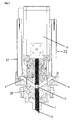
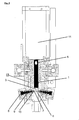
- FIG. 1-3 is a highly schematic representation of an inventive mixing head in two different sectional planes ( Fig. 1 and 2 with first cutting plane, Fig. 3 with second cutting plane).
- the mixing head comprises a multi-part housing 20, in which a mixing chamber 6 in the form of a cylindrical chamber is arranged.
- the mixing chamber 6 has at the lower end to an outlet through which the reactive, mixed together, components from the mixing head and can be introduced, for example, in a closed tool.
- the reactive components to be mixed in the mixing head are fed by means of different lines, as will be explained below.
- a high-viscosity starting material for example a fiber-added polyol material, is supplied to the mixing head via a supply line 21.
- the supply line 21 can be connected to the mixing chamber 6 via a supply channel 3 provided in the mixing head.
- a reflux line 22 is connected to the mixing head, and the reflux line 22 is fluidly connectable via a also provided in the mixing head reflux channel 4 with de, supply channel 3. Both the supply channel 3 and the return flow channel 4 terminate axially at the same height in the mixing chamber 6.
- a bolt-shaped cleaning piston is added, which substantially fills the mixing chamber 6 in terms of its diameter, but up and down hin- and let it move.
- Fig. 1 the cleaning piston 1 is shown in an advanced position.
- the drive of the cleaning piston is realized by a separate motor 11.
- the cleaning piston 1 has a bore 5, which is arranged in the cleaning piston 1, that in the in Fig. 1 shown pre-process position on the bore 5, a flow connection between the supply channel 3 and the return flow channel 4 is formed. In this way, a recirculation of the high-viscosity starting material from a day tank via the supply line 21, the supply channel 3, the bore 5, the return flow channel 4 and the return flow line 22 back realize in the day container.
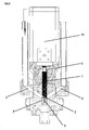
- Fig. 2 the cleaning piston 1 is shown in retracted position.
- the bore is displaced upward, so that the flow connection between the supply channel 3 and the return flow channel 4 is interrupted.
- the cleaning piston is retracted to an extent that now a flow connection between the supply channel 3 and the mixing chamber 6 is made.
- the nose serves at the same time blocking against the return flow channel 4, so that no high-viscosity starting material in this position of the cleaning piston 1 can now get into the return. Since the flow cross-sections in the feed channel 3 and in the transition to the mixing chamber 6 and in the mixing chamber 6 itself are dimensioned relatively equal, there is again no dysfunctional disturbance when introducing the high-viscosity starting material in the mixing chamber more.
- injection ports 7 also called injection wells
- Fig. 2 three can be seen
- injection openings 7 are arranged downstream of the supply of high-viscosity starting material in the mixing chamber 6.
- six are circular around the mixing chamber 6 arranged injection openings provided.
- a separate injection nozzle is provided for each injection opening and accommodated in the housing 20.
- Each nozzle has a nozzle needle 9 and a nozzle cone 10, wherein the nozzle needle 9 can release the nozzle cone 10 or close.
- the nozzle needle 9 is moved back or forth via an actuating piston 8, which is hydraulically acted upon.
- actuating piston 8 Depending on the position of the actuating piston 8, a connection between a supply, not shown, for this starting material via the injection nozzle and the injection port 7 to the mixing chamber 6 is released or closed.
- the low-viscosity starting material which is introduced via the injection openings 7 in the mixing chamber 6, is under very high pressure, so that it comes together with the present in very highly viscous form first starting material to an intimate mixing.
- the cleaning piston 1 Before an injection and mixing process, the cleaning piston 1 is in the advanced position of Fig. 1 , whereby it comes to a recirculation at the high-viscosity starting material via the bore 5. At the same time, the injection nozzles 10 are closed, so that no starting material can reach the mixing chamber via the injection openings. This would prevent, inter alia, the still advanced cleaning piston 1. Also in the injection nozzles 10 and for the low-viscosity starting material, a recirculation can be provided.
- the cleaning piston 1 in the in Fig. 2 reverse the position shown.
- the recirculation of the high-viscosity starting material from the supply channel 3 via the return flow channel 4 is suppressed.
- the cleaning piston 1 releases the flow connection from the feed channel 3 to the mixing chamber 6 the highly viscous starting material enters the mixing chamber 6.
- the injection nozzles 10 can be opened by retracting the nozzle needle 9.
- the low-viscosity starting material passes into the mixing chamber 6, in which now also the highly viscous starting material is.
- the injection timing is chosen so that the injection begins as soon as first parts of the highly viscous starting material into the mixing chamber 6 arrive.
- the promotion of the high-viscosity starting material in the mixing chamber with simultaneous injection of the low-viscosity starting material is carried out until a sufficient amount of reactive components via the discharge opening in a foaming mold - in particular a closed foam mold - is introduced.
- the cleaning piston 1 is again in the in Fig. 1 shown position, wherein the connection between the supply channel 5 and the mixing chamber 6 is interrupted, the mixing chamber cleaned and the recirculation of the high-viscosity starting material via the bore 5 is restored.
Landscapes
- Engineering & Computer Science (AREA)
- Mechanical Engineering (AREA)
- Processing And Handling Of Plastics And Other Materials For Molding In General (AREA)
- Injection Moulding Of Plastics Or The Like (AREA)
- Mixers Of The Rotary Stirring Type (AREA)
- Paper (AREA)
- Glass Compositions (AREA)
- Powder Metallurgy (AREA)
Claims (13)
- Tête de mélange, pour mélanger au moins deux matières de départ réactives, notamment pour un procédé de coulage par réaction, dont au moins une matière de départ se présente sous forme hautement visqueuse, notamment chargé d'agents de remplissage, comprenant- un canal d'alimentation (3) pour une matière de départ,- un canal de retour (4) pour la matière de départ,- une chambre de mélange(6), qui dans une position de fonctionnement reçoit une matière de départ du canal d'alimentation (3) et dans laquelle les matières de départ sont mélangées entre elles,
un dispositif de commutation (1) étant prévu, à l'aide duquel au choix une liaison par écoulement (2) peut être établie entre le canal d'alimentation (3) et la chambre de mélange (6) d'une part, ou entre le canal d'alimentation (3) et le canal de retour (4) d'autre part, et- au moins un orifice d'injection (7) pour l'introduction d'une matière de départ supplémentaire de plus faible viscosité dans la chambre de mélange (6),
l'alimentation du canal d'alimentation (3) vers la chambre de mélange (6) étant prévue en amont de l'au moins un orifice d'injection (7),
caractérisée en ce que,
dans une position de fonctionnement du dispositif de commutation, le canal d'alimentation (3) débouche directement dans la chambre de mélange (6),
en ce que le canal d'alimentation (3) est conçu pour laisser passer une matière de départ hautement visqueuse, et
en ce que le canal de retour (4) est conçu pour laisser passer la matière de départ hautement visqueuse. - Tête de mélange selon la revendication 1,
caractérisée en ce que,
le canal d'alimentation (3), le canal de retour (4) et la liaison par écoulement (5) entre le canal d'alimentation (3) et le canal de retour (4) sont conçus sensiblement sans rétrécissement excessif de la section transversale, notamment avec la même section transversale d'écoulement. - Tête de mélange selon la revendication 1 ou 2,
caractérisée en ce que,
la liaison par écoulement entre le canal d'alimentation (3) et la chambre de mélange (6) présente sensiblement la même section transversale d'écoulement que celle du canal d'alimentation (3). - Tête de mélange selon l'une quelconque des revendications 1 à 3,
caractérisée en ce que,- un piston de nettoyage (1) est guidé en étant mobile de part et d'autre dans la chambre de mélange (6),- en ce que dans une position, le piston de nettoyage (1) établit une liaison par écoulement (5) entre le canal d'alimentation (3) et le canal de retour (4) et dans une deuxième position, une liaison par écoulement (2) entre le canal d'alimentation (3) et la chambre de mélange (6). - Tête de mélange selon la revendication 4,
caractérisée en ce que
l'extrémité du piston de nettoyage (1) est conçue de sorte que la matière de départ hautement visqueuse soit déviée du canal d'alimentation (3) dans la chambre de mélange (6). - Tête de mélange selon l'une quelconque des revendications précédentes,
caractérisée en ce que
plusieurs orifices d'injection (7) sont prévus. - Tête de mélange selon la revendication 6,
caractérisée en ce que,
les orifices d'injection (7) sont disposés sous forme approximativement annulaire autour de la chambre de mélange (6). - Tête de mélange selon l'une quelconque des revendications 1 à 7,
caractérisée en ce que,
vers chaque orifice d'injection (7) est prévu un injecteur (8, 9, 10), au moyen duquel la matière de départ moins visqueuse est injectée dans la chambre de mélange (6). - Tête de mélange selon la revendication 8,
caractérisée en ce que,
les injecteurs (8, 9, 10) sont conçus pour être actionnables séparément. - Tête de mélange selon l'une quelconque des revendications précédentes,
caractérisé en ce que,
l'orifice d'injection (7) et/ou l'injecteur (8, 9, 10) sont conçus de sorte que la matière de départ moins visqueuse soit susceptible d'être injectée sous une haute pression dans la chambre de mélange. - Procédé, notamment procédé de coulage par réaction pour faire fonctionner une tête de mélange, consistant à mélanger deux matières de départ réactives, dont une matière de départ hautement visqueuse est mélangée à des fibres, qui présentent au moins en partie une longueur supérieure à 0,5 mm, notamment supérieure à 1 mm, de préférence supérieure à 3 mm avec les étapes (répétées de préférence de façon cyclique) selon lesquelles- avant un processus de mélange, on relie un canal d'alimentation pour la matière de départ hautement visqueuse, chargée de fibres avec un conduit de retour, pour la recirculation, sensiblement sous maintien de la section transversale d'écoulement,- pour l'initiation du processus de mélange, on relie le canal d'alimentation avec la chambre de mélange, la liaison par écoulement du conduit d'alimentation vers le conduit de retour étant interrompue,- lors du processus de mélange, on introduit la matière hautement visqueuse, chargée de fibres dans la chambre de mélange,- on injecte une matière de départ supplémentaire, moins visqueuse via des injecteurs dans la chambre de mélange, en aval de l'alimentation de la matière de départ hautement visqueuse, eton évacue le mélange réactif hors de la chambre de mélange.
- Procédé selon la revendication 11,
caractérisé en ce que,
on introduit la matière de départ hautement viscose sous basse pression dans la chambre de mélange. - Procédé selon la revendication 11 ou 12,
caractérisé en ce que,
on injecte la matière de départ moins visqueuse sous haute pression dans la chambre de mélange.
Priority Applications (2)
| Application Number | Priority Date | Filing Date | Title |
|---|---|---|---|
| PL06754734T PL1855858T3 (pl) | 2005-02-22 | 2006-01-12 | Głowica mieszająca dla materiału wyjściowego o dużej lepkości |
| SI200630292T SI1855858T1 (sl) | 2005-02-22 | 2006-01-12 | Meĺ alna glava za visoko viskozne zaäśetne materiale |
Applications Claiming Priority (2)
| Application Number | Priority Date | Filing Date | Title |
|---|---|---|---|
| DE102005007979A DE102005007979A1 (de) | 2005-02-22 | 2005-02-22 | Mischkopf für hochviskoses Ausgangsmaterial |
| PCT/EP2006/050181 WO2006089816A1 (fr) | 2005-02-22 | 2006-01-12 | Tete de melange pour materiau de depart tres visqueux |
Publications (2)
| Publication Number | Publication Date |
|---|---|
| EP1855858A1 EP1855858A1 (fr) | 2007-11-21 |
| EP1855858B1 true EP1855858B1 (fr) | 2009-04-01 |
Family
ID=36168933
Family Applications (1)
| Application Number | Title | Priority Date | Filing Date |
|---|---|---|---|
| EP06754734A Active EP1855858B1 (fr) | 2005-02-22 | 2006-01-12 | Tete de melange pour materiau de depart tres visqueux |
Country Status (10)
| Country | Link |
|---|---|
| US (1) | US20080002519A1 (fr) |
| EP (1) | EP1855858B1 (fr) |
| CN (1) | CN101128295B (fr) |
| AT (1) | ATE427198T1 (fr) |
| DE (2) | DE102005007979A1 (fr) |
| DK (1) | DK1855858T3 (fr) |
| ES (1) | ES2321762T3 (fr) |
| PL (1) | PL1855858T3 (fr) |
| SI (1) | SI1855858T1 (fr) |
| WO (1) | WO2006089816A1 (fr) |
Families Citing this family (7)
| Publication number | Priority date | Publication date | Assignee | Title |
|---|---|---|---|---|
| US8511047B2 (en) * | 2007-08-07 | 2013-08-20 | Sealed Air Corporation (Us) | Device for mixing and dispensing fluids |
| DE102007050332B4 (de) | 2007-10-18 | 2010-12-02 | Kraussmaffei Technologies Gmbh | Formwerkzeug mit integriertem Injektor |
| CN104589585B (zh) * | 2014-12-31 | 2017-03-29 | 苏州市博奥塑胶电子有限公司 | 注塑机喷嘴 |
| CN108393240A (zh) * | 2018-04-25 | 2018-08-14 | 大连华工创新科技股份有限公司 | 适用于双组分高粘度物料的注胶头 |
| CN111347577B (zh) * | 2020-03-23 | 2022-01-11 | 株洲市圣翰有色焊材有限公司 | 一种基于往复挤压原理的新材料混合装置 |
| CN111569684B (zh) * | 2020-05-28 | 2022-04-15 | 中国石油大学(华东) | 一种微纳米气泡发生器 |
| CN112659449B (zh) * | 2020-12-03 | 2022-06-07 | 长虹美菱股份有限公司 | 一种转换型聚氨酯注料枪头 |
Citations (1)
| Publication number | Priority date | Publication date | Assignee | Title |
|---|---|---|---|---|
| EP0879685A2 (fr) * | 1997-05-22 | 1998-11-25 | Afros S.P.A. | Mélangeur autonettoyant et procédé pour la fabrication de mixture polyurethanes |
Family Cites Families (13)
| Publication number | Priority date | Publication date | Assignee | Title |
|---|---|---|---|---|
| DE1278099B (de) * | 1961-06-30 | 1968-09-19 | Baer Maschf Josef | Vorrichtung zum Mischen von Kunstharzen |
| DE2823189A1 (de) * | 1978-05-27 | 1979-11-29 | Desma Werke Gmbh | Mischkopf, insbesondere fuer die formschaeumung von polyurethanen |
| DE3238258C2 (de) * | 1982-02-26 | 1984-05-17 | Krauss-Maffei AG, 8000 München | Mischkopf |
| US4600312A (en) * | 1985-03-08 | 1986-07-15 | Ex-Cell-O Corporation | Impingement mix-head for rim process |
| US5201580A (en) * | 1985-07-12 | 1993-04-13 | Krauss Maffei Aktiengesellschaft | Impingement mixing device |
| JPS63218323A (ja) * | 1987-03-06 | 1988-09-12 | Toyoda Gosei Co Ltd | 反応射出成形機用の計量装置 |
| JPH02107322A (ja) * | 1988-10-13 | 1990-04-19 | Toho Kikai Kogyo Kk | 混合ヘッド |
| US5445781A (en) * | 1991-08-28 | 1995-08-29 | Centro Sviluppo Settori Impiego S.R.L. | Process for the injection molding of non-precatalyzed polymerizable resins at high-pressure and flow |
| DE19515039C2 (de) * | 1995-04-24 | 1998-10-01 | Krauss Maffei Ag | Vorrichtung zum Mischen von wenigstens zwei chemisch reaktiven Kunststoffkomponenten |
| DE29521023U1 (de) * | 1995-05-08 | 1996-08-01 | Krauss Maffei Ag | Reaktionsgießmaschine |
| DE29704560U1 (de) * | 1996-07-04 | 1997-08-28 | Hennecke Gmbh | Hochdruckmischkopf |
| DE19716982A1 (de) * | 1997-04-23 | 1998-10-29 | Hennecke Gmbh | Vorrichtung zur Entfernung von Kunststoffrückständen von Mischkopf-Auslaufrohren |
| CA2339216A1 (fr) * | 1998-08-01 | 2000-02-17 | Krauss-Maffei Kunststofftechnik Gmbh | Dispositif pour produire un melange impregne de fibres naturelles a partir de composes de plastiques chimiquement reactifs |
-
2005
- 2005-02-22 DE DE102005007979A patent/DE102005007979A1/de not_active Ceased
-
2006
- 2006-01-12 EP EP06754734A patent/EP1855858B1/fr active Active
- 2006-01-12 ES ES06754734T patent/ES2321762T3/es active Active
- 2006-01-12 CN CN2006800055455A patent/CN101128295B/zh not_active Expired - Fee Related
- 2006-01-12 SI SI200630292T patent/SI1855858T1/sl unknown
- 2006-01-12 PL PL06754734T patent/PL1855858T3/pl unknown
- 2006-01-12 AT AT06754734T patent/ATE427198T1/de not_active IP Right Cessation
- 2006-01-12 DE DE502006003319T patent/DE502006003319D1/de active Active
- 2006-01-12 DK DK06754734T patent/DK1855858T3/da active
- 2006-01-12 WO PCT/EP2006/050181 patent/WO2006089816A1/fr active Application Filing
-
2007
- 2007-08-16 US US11/839,848 patent/US20080002519A1/en not_active Abandoned
Patent Citations (1)
| Publication number | Priority date | Publication date | Assignee | Title |
|---|---|---|---|---|
| EP0879685A2 (fr) * | 1997-05-22 | 1998-11-25 | Afros S.P.A. | Mélangeur autonettoyant et procédé pour la fabrication de mixture polyurethanes |
Also Published As
| Publication number | Publication date |
|---|---|
| DE502006003319D1 (de) | 2009-05-14 |
| US20080002519A1 (en) | 2008-01-03 |
| PL1855858T3 (pl) | 2009-08-31 |
| EP1855858A1 (fr) | 2007-11-21 |
| SI1855858T1 (sl) | 2009-08-31 |
| ATE427198T1 (de) | 2009-04-15 |
| ES2321762T3 (es) | 2009-06-10 |
| WO2006089816A1 (fr) | 2006-08-31 |
| DK1855858T3 (da) | 2009-05-25 |
| DE102005007979A1 (de) | 2006-08-24 |
| CN101128295A (zh) | 2008-02-20 |
| CN101128295B (zh) | 2011-04-27 |
Similar Documents
| Publication | Publication Date | Title |
|---|---|---|
| EP1855858B1 (fr) | Tete de melange pour materiau de depart tres visqueux | |
| EP0137250B1 (fr) | Buse multiple pour réunir au moins deux réactants fluides formant de la matière plastique, en particulier de la matière plastique alvéolaire, en vue de déclencher la réaction par mélange et procédé pour le fonctionnement de ladite buse multiple | |
| EP0024608B1 (fr) | Procédé et dispositif de production de pièces moulées à partir d'un mélange fluide réactionnel formant une matière pleine ou expansée | |
| EP0196345B1 (fr) | Procédé et dispositif pour produire des mousses | |
| EP0260564B1 (fr) | Procédé et dispositif pour la fabrication en continu d'une matière plastique, en particulier d'un mélange réactif liquide formant une mousse à partir d'au moins deux composants liquides | |
| EP0099045B1 (fr) | Méthode et tête de mélange pour la fabrication d'un mélange ayant au moins deux composants réactifs pouvant couler et formant une matière plastique | |
| EP2403698B1 (fr) | Dispositif de fabrication d'éléments en plastique contenant des fibres de renforcement | |
| DE3014175A1 (de) | Verfahren und vorrichtung zum einspritzmischen und -abgeben fuer hochgeschwindigkeitsreaktionen | |
| DE112012006895T5 (de) | Mischkopf mit verbesserter Mischungsleistung und Austragsvorrichtung für denselben | |
| DE102016104503B4 (de) | Formgebungsverfahren | |
| DE3200503A1 (de) | "vorrichtung zum mischen miteinander reagierender chemischer komponenten" | |
| WO2000012285A1 (fr) | Procede et dispositif de moulage par injection d'une matiere plastique | |
| DE4340990A1 (de) | Verfahren und Vorrichtung zum Spritzgießen von mehrschichtigen Gegenständen | |
| EP3600681B1 (fr) | Unité formant buse pour une machine de moulage par réaction ainsi que procédé de fabrication d'une pièce en matière plastique | |
| AT518860B1 (de) | Verfahren zur Herstellung von Kunststoffbauteilen | |
| EP0394790B1 (fr) | Dispositif pour la fabrication d'un mélange réactif apte à couler à partir d'au moins deux composants réactifs aptes à couler pour la fabrication de matières plastiques massives ou cellulaires | |
| DE2550334A1 (de) | Angussvorrichtung fuer die formgebende verarbeitung von kunststoffen | |
| DE102016208191A1 (de) | Mischvorrichtung und Verfahren zum Mischen zumindest zweier Komponenten und Ausgeben eines Gemisches davon | |
| DE102018214410A1 (de) | Mischvorrichtung sowie Verfahren zum Ausbilden eines Bauteils | |
| EP0271803A2 (fr) | Dispositif pour mélanger au moins deux composants de réaction aptes à s'écouler pour former des matières plastiques massives ou écumeuses | |
| DE102010048046A1 (de) | Variabler Heißkanalverteiler in einer Kunststoffspritzmaschine | |
| DE3331840A1 (de) | Mehrstoffduese zum zusammenfuehren mindestens zweier fliessfaehiger, kunststoff, insbesondere schaumstoff bildender reaktionskomponenten zum zwecke des einleitens der reaktion durch vermischung und verfahren zum betrieb dieser mehrstoffduese | |
| DE10233447A1 (de) | Coinjections-Einheit für Spritzgießmaschinen | |
| DE7006182U (de) | Vorrichtung zum erzeugen und einleiten eines vorzugsweise chemisch reaktionsfaehigen gemisches aus zwei oder mehr kunststoffkomponenten in den hohlraum einer form. | |
| EP0836924A1 (fr) | Procédé et dispositif pour la fabrication d'une pièce en matière plastique avec un espace creux pratiquement fermé |
Legal Events
| Date | Code | Title | Description |
|---|---|---|---|
| PUAI | Public reference made under article 153(3) epc to a published international application that has entered the european phase |
Free format text: ORIGINAL CODE: 0009012 |
|
| 17P | Request for examination filed |
Effective date: 20070924 |
|
| AK | Designated contracting states |
Kind code of ref document: A1 Designated state(s): AT BE BG CH CY CZ DE DK EE ES FI FR GB GR HU IE IS IT LI LT LU LV MC NL PL PT RO SE SI SK TR |
|
| RAP1 | Party data changed (applicant data changed or rights of an application transferred) |
Owner name: KRAUSMAFFEI TECHNOLOGIES GMBH |
|
| 17Q | First examination report despatched |
Effective date: 20071213 |
|
| RAP1 | Party data changed (applicant data changed or rights of an application transferred) |
Owner name: KRAUSSMAFFEI TECHNOLOGIES GMBH |
|
| DAX | Request for extension of the european patent (deleted) | ||
| GRAP | Despatch of communication of intention to grant a patent |
Free format text: ORIGINAL CODE: EPIDOSNIGR1 |
|
| GRAS | Grant fee paid |
Free format text: ORIGINAL CODE: EPIDOSNIGR3 |
|
| GRAA | (expected) grant |
Free format text: ORIGINAL CODE: 0009210 |
|
| AK | Designated contracting states |
Kind code of ref document: B1 Designated state(s): AT BE BG CH CY CZ DE DK EE ES FI FR GB GR HU IE IS IT LI LT LU LV MC NL PL PT RO SE SI SK TR |
|
| REG | Reference to a national code |
Ref country code: GB Ref legal event code: FG4D Free format text: NOT ENGLISH |
|
| REG | Reference to a national code |
Ref country code: CH Ref legal event code: EP |
|
| REG | Reference to a national code |
Ref country code: IE Ref legal event code: FG4D Free format text: LANGUAGE OF EP DOCUMENT: GERMAN |
|
| REF | Corresponds to: |
Ref document number: 502006003319 Country of ref document: DE Date of ref document: 20090514 Kind code of ref document: P |
|
| REG | Reference to a national code |
Ref country code: DK Ref legal event code: T3 |
|
| REG | Reference to a national code |
Ref country code: ES Ref legal event code: FG2A Ref document number: 2321762 Country of ref document: ES Kind code of ref document: T3 |
|
| REG | Reference to a national code |
Ref country code: RO Ref legal event code: EPE |
|
| REG | Reference to a national code |
Ref country code: PL Ref legal event code: T3 |
|
| REG | Reference to a national code |
Ref country code: IE Ref legal event code: FD4D |
|
| PG25 | Lapsed in a contracting state [announced via postgrant information from national office to epo] |
Ref country code: FI Free format text: LAPSE BECAUSE OF FAILURE TO SUBMIT A TRANSLATION OF THE DESCRIPTION OR TO PAY THE FEE WITHIN THE PRESCRIBED TIME-LIMIT Effective date: 20090401 Ref country code: LT Free format text: LAPSE BECAUSE OF FAILURE TO SUBMIT A TRANSLATION OF THE DESCRIPTION OR TO PAY THE FEE WITHIN THE PRESCRIBED TIME-LIMIT Effective date: 20090401 Ref country code: EE Free format text: LAPSE BECAUSE OF FAILURE TO SUBMIT A TRANSLATION OF THE DESCRIPTION OR TO PAY THE FEE WITHIN THE PRESCRIBED TIME-LIMIT Effective date: 20090401 Ref country code: PT Free format text: LAPSE BECAUSE OF FAILURE TO SUBMIT A TRANSLATION OF THE DESCRIPTION OR TO PAY THE FEE WITHIN THE PRESCRIBED TIME-LIMIT Effective date: 20090902 |
|
| PG25 | Lapsed in a contracting state [announced via postgrant information from national office to epo] |
Ref country code: LV Free format text: LAPSE BECAUSE OF FAILURE TO SUBMIT A TRANSLATION OF THE DESCRIPTION OR TO PAY THE FEE WITHIN THE PRESCRIBED TIME-LIMIT Effective date: 20090401 Ref country code: SE Free format text: LAPSE BECAUSE OF FAILURE TO SUBMIT A TRANSLATION OF THE DESCRIPTION OR TO PAY THE FEE WITHIN THE PRESCRIBED TIME-LIMIT Effective date: 20090701 Ref country code: IS Free format text: LAPSE BECAUSE OF FAILURE TO SUBMIT A TRANSLATION OF THE DESCRIPTION OR TO PAY THE FEE WITHIN THE PRESCRIBED TIME-LIMIT Effective date: 20090801 |
|
| REG | Reference to a national code |
Ref country code: HU Ref legal event code: AG4A Ref document number: E006246 Country of ref document: HU |
|
| PG25 | Lapsed in a contracting state [announced via postgrant information from national office to epo] |
Ref country code: IE Free format text: LAPSE BECAUSE OF FAILURE TO SUBMIT A TRANSLATION OF THE DESCRIPTION OR TO PAY THE FEE WITHIN THE PRESCRIBED TIME-LIMIT Effective date: 20090401 |
|
| PLBE | No opposition filed within time limit |
Free format text: ORIGINAL CODE: 0009261 |
|
| STAA | Information on the status of an ep patent application or granted ep patent |
Free format text: STATUS: NO OPPOSITION FILED WITHIN TIME LIMIT |
|
| PGFP | Annual fee paid to national office [announced via postgrant information from national office to epo] |
Ref country code: PL Payment date: 20091228 Year of fee payment: 5 Ref country code: RO Payment date: 20091229 Year of fee payment: 5 |
|
| 26N | No opposition filed |
Effective date: 20100105 |
|
| PG25 | Lapsed in a contracting state [announced via postgrant information from national office to epo] |
Ref country code: BG Free format text: LAPSE BECAUSE OF FAILURE TO SUBMIT A TRANSLATION OF THE DESCRIPTION OR TO PAY THE FEE WITHIN THE PRESCRIBED TIME-LIMIT Effective date: 20090701 |
|
| PGFP | Annual fee paid to national office [announced via postgrant information from national office to epo] |
Ref country code: DK Payment date: 20100113 Year of fee payment: 5 Ref country code: HU Payment date: 20100204 Year of fee payment: 5 |
|
| PGFP | Annual fee paid to national office [announced via postgrant information from national office to epo] |
Ref country code: SI Payment date: 20100104 Year of fee payment: 5 |
|
| PGFP | Annual fee paid to national office [announced via postgrant information from national office to epo] |
Ref country code: BE Payment date: 20100112 Year of fee payment: 5 |
|
| PG25 | Lapsed in a contracting state [announced via postgrant information from national office to epo] |
Ref country code: MC Free format text: LAPSE BECAUSE OF NON-PAYMENT OF DUE FEES Effective date: 20100131 |
|
| PGFP | Annual fee paid to national office [announced via postgrant information from national office to epo] |
Ref country code: NL Payment date: 20100118 Year of fee payment: 5 |
|
| REG | Reference to a national code |
Ref country code: CH Ref legal event code: PL |
|
| PG25 | Lapsed in a contracting state [announced via postgrant information from national office to epo] |
Ref country code: LI Free format text: LAPSE BECAUSE OF NON-PAYMENT OF DUE FEES Effective date: 20100131 Ref country code: GR Free format text: LAPSE BECAUSE OF FAILURE TO SUBMIT A TRANSLATION OF THE DESCRIPTION OR TO PAY THE FEE WITHIN THE PRESCRIBED TIME-LIMIT Effective date: 20090702 Ref country code: CH Free format text: LAPSE BECAUSE OF NON-PAYMENT OF DUE FEES Effective date: 20100131 |
|
| BERE | Be: lapsed |
Owner name: KRAUSSMAFFEI TECHNOLOGIES G.M.B.H. Effective date: 20110131 |
|
| REG | Reference to a national code |
Ref country code: NL Ref legal event code: V1 Effective date: 20110801 |
|
| REG | Reference to a national code |
Ref country code: DK Ref legal event code: EBP |
|
| REG | Reference to a national code |
Ref country code: SI Ref legal event code: KO00 Effective date: 20110901 |
|
| PG25 | Lapsed in a contracting state [announced via postgrant information from national office to epo] |
Ref country code: BE Free format text: LAPSE BECAUSE OF NON-PAYMENT OF DUE FEES Effective date: 20110131 Ref country code: HU Free format text: LAPSE BECAUSE OF NON-PAYMENT OF DUE FEES Effective date: 20110113 Ref country code: SI Free format text: LAPSE BECAUSE OF NON-PAYMENT OF DUE FEES Effective date: 20110113 |
|
| PG25 | Lapsed in a contracting state [announced via postgrant information from national office to epo] |
Ref country code: NL Free format text: LAPSE BECAUSE OF NON-PAYMENT OF DUE FEES Effective date: 20110801 |
|
| REG | Reference to a national code |
Ref country code: AT Ref legal event code: MM01 Ref document number: 427198 Country of ref document: AT Kind code of ref document: T Effective date: 20110112 |
|
| PGFP | Annual fee paid to national office [announced via postgrant information from national office to epo] |
Ref country code: TR Payment date: 20120214 Year of fee payment: 7 |
|
| PG25 | Lapsed in a contracting state [announced via postgrant information from national office to epo] |
Ref country code: CY Free format text: LAPSE BECAUSE OF FAILURE TO SUBMIT A TRANSLATION OF THE DESCRIPTION OR TO PAY THE FEE WITHIN THE PRESCRIBED TIME-LIMIT Effective date: 20090401 |
|
| PG25 | Lapsed in a contracting state [announced via postgrant information from national office to epo] |
Ref country code: LU Free format text: LAPSE BECAUSE OF NON-PAYMENT OF DUE FEES Effective date: 20100112 |
|
| PG25 | Lapsed in a contracting state [announced via postgrant information from national office to epo] |
Ref country code: PL Free format text: LAPSE BECAUSE OF NON-PAYMENT OF DUE FEES Effective date: 20110112 |
|
| REG | Reference to a national code |
Ref country code: PL Ref legal event code: LAPE |
|
| PG25 | Lapsed in a contracting state [announced via postgrant information from national office to epo] |
Ref country code: AT Free format text: LAPSE BECAUSE OF NON-PAYMENT OF DUE FEES Effective date: 20110112 |
|
| PGFP | Annual fee paid to national office [announced via postgrant information from national office to epo] |
Ref country code: ES Payment date: 20130117 Year of fee payment: 8 Ref country code: CZ Payment date: 20130107 Year of fee payment: 8 |
|
| REG | Reference to a national code |
Ref country code: DE Ref legal event code: R082 Ref document number: 502006003319 Country of ref document: DE Representative=s name: WILHELM, LUDWIG, DIPL.-PHYS., DE |
|
| REG | Reference to a national code |
Ref country code: DE Ref legal event code: R082 Ref document number: 502006003319 Country of ref document: DE Representative=s name: WILHELM, LUDWIG, DIPL.-PHYS., DE Effective date: 20130603 Ref country code: DE Ref legal event code: R081 Ref document number: 502006003319 Country of ref document: DE Owner name: KRAUSSMAFFEI TECHNOLOGIES GMBH, DE Free format text: FORMER OWNER: KRAUSSMAFFEI TECHNOLOGIES GMBH, 80997 MUENCHEN, DE Effective date: 20130603 |
|
| PGFP | Annual fee paid to national office [announced via postgrant information from national office to epo] |
Ref country code: SK Payment date: 20140109 Year of fee payment: 9 Ref country code: DE Payment date: 20140122 Year of fee payment: 9 |
|
| PGFP | Annual fee paid to national office [announced via postgrant information from national office to epo] |
Ref country code: FR Payment date: 20140123 Year of fee payment: 9 Ref country code: IT Payment date: 20140124 Year of fee payment: 9 |
|
| PGFP | Annual fee paid to national office [announced via postgrant information from national office to epo] |
Ref country code: GB Payment date: 20140121 Year of fee payment: 9 |
|
| PG25 | Lapsed in a contracting state [announced via postgrant information from national office to epo] |
Ref country code: CZ Free format text: LAPSE BECAUSE OF NON-PAYMENT OF DUE FEES Effective date: 20140112 |
|
| REG | Reference to a national code |
Ref country code: DE Ref legal event code: R119 Ref document number: 502006003319 Country of ref document: DE |
|
| REG | Reference to a national code |
Ref country code: ES Ref legal event code: FD2A Effective date: 20150828 |
|
| GBPC | Gb: european patent ceased through non-payment of renewal fee |
Effective date: 20150112 |
|
| REG | Reference to a national code |
Ref country code: SK Ref legal event code: MM4A Ref document number: E 5604 Country of ref document: SK Effective date: 20150112 |
|
| PG25 | Lapsed in a contracting state [announced via postgrant information from national office to epo] |
Ref country code: ES Free format text: LAPSE BECAUSE OF NON-PAYMENT OF DUE FEES Effective date: 20140113 Ref country code: SK Free format text: LAPSE BECAUSE OF NON-PAYMENT OF DUE FEES Effective date: 20150112 Ref country code: DE Free format text: LAPSE BECAUSE OF NON-PAYMENT OF DUE FEES Effective date: 20150801 Ref country code: GB Free format text: LAPSE BECAUSE OF NON-PAYMENT OF DUE FEES Effective date: 20150112 |
|
| REG | Reference to a national code |
Ref country code: FR Ref legal event code: ST Effective date: 20150930 |
|
| PG25 | Lapsed in a contracting state [announced via postgrant information from national office to epo] |
Ref country code: FR Free format text: LAPSE BECAUSE OF NON-PAYMENT OF DUE FEES Effective date: 20150202 |
|
| PG25 | Lapsed in a contracting state [announced via postgrant information from national office to epo] |
Ref country code: IT Free format text: LAPSE BECAUSE OF NON-PAYMENT OF DUE FEES Effective date: 20150112 |
|
| PG25 | Lapsed in a contracting state [announced via postgrant information from national office to epo] |
Ref country code: TR Free format text: LAPSE BECAUSE OF NON-PAYMENT OF DUE FEES Effective date: 20140112 |