EP1852233B1 - Wasserversorgungsvorrichtung für einen kernbohrer - Google Patents
Wasserversorgungsvorrichtung für einen kernbohrer Download PDFInfo
- Publication number
- EP1852233B1 EP1852233B1 EP06711462.9A EP06711462A EP1852233B1 EP 1852233 B1 EP1852233 B1 EP 1852233B1 EP 06711462 A EP06711462 A EP 06711462A EP 1852233 B1 EP1852233 B1 EP 1852233B1
- Authority
- EP
- European Patent Office
- Prior art keywords
- water
- adapter
- storage tank
- water storage
- mounting portion
- Prior art date
- Legal status (The legal status is an assumption and is not a legal conclusion. Google has not performed a legal analysis and makes no representation as to the accuracy of the status listed.)
- Expired - Lifetime
Links
Images





Classifications
-
- B—PERFORMING OPERATIONS; TRANSPORTING
- B28—WORKING CEMENT, CLAY, OR STONE
- B28D—WORKING STONE OR STONE-LIKE MATERIALS
- B28D7/00—Accessories specially adapted for use with machines or devices of the preceding groups
- B28D7/02—Accessories specially adapted for use with machines or devices of the preceding groups for removing or laying dust, e.g. by spraying liquids; for cooling work
-
- B—PERFORMING OPERATIONS; TRANSPORTING
- B28—WORKING CEMENT, CLAY, OR STONE
- B28D—WORKING STONE OR STONE-LIKE MATERIALS
- B28D1/00—Working stone or stone-like materials, e.g. brick, concrete or glass, not provided for elsewhere; Machines, devices, tools therefor
- B28D1/14—Working stone or stone-like materials, e.g. brick, concrete or glass, not provided for elsewhere; Machines, devices, tools therefor by boring or drilling
-
- Y—GENERAL TAGGING OF NEW TECHNOLOGICAL DEVELOPMENTS; GENERAL TAGGING OF CROSS-SECTIONAL TECHNOLOGIES SPANNING OVER SEVERAL SECTIONS OF THE IPC; TECHNICAL SUBJECTS COVERED BY FORMER USPC CROSS-REFERENCE ART COLLECTIONS [XRACs] AND DIGESTS
- Y10—TECHNICAL SUBJECTS COVERED BY FORMER USPC
- Y10T—TECHNICAL SUBJECTS COVERED BY FORMER US CLASSIFICATION
- Y10T408/00—Cutting by use of rotating axially moving tool
- Y10T408/44—Cutting by use of rotating axially moving tool with means to apply transient, fluent medium to work or product
-
- Y—GENERAL TAGGING OF NEW TECHNOLOGICAL DEVELOPMENTS; GENERAL TAGGING OF CROSS-SECTIONAL TECHNOLOGIES SPANNING OVER SEVERAL SECTIONS OF THE IPC; TECHNICAL SUBJECTS COVERED BY FORMER USPC CROSS-REFERENCE ART COLLECTIONS [XRACs] AND DIGESTS
- Y10—TECHNICAL SUBJECTS COVERED BY FORMER USPC
- Y10T—TECHNICAL SUBJECTS COVERED BY FORMER US CLASSIFICATION
- Y10T408/00—Cutting by use of rotating axially moving tool
- Y10T408/44—Cutting by use of rotating axially moving tool with means to apply transient, fluent medium to work or product
- Y10T408/45—Cutting by use of rotating axially moving tool with means to apply transient, fluent medium to work or product including Tool with duct
Definitions
- the present invention relates to a water feed apparatus for use with a core drill of a wet type in which a core body is rotationally driven by a drive mechanism to drill a hole in an object to be drilled, and water is fed to cutting blades provided on the core body, and more particularly, to a water feed apparatus which has a compact construction, and which realizes a sufficient water feed even at high-speed rotation of the core body.
- a core drill is widely used for drilling a hole in concrete and the like.
- This core drill is generally of the construction in which a drive mechanism for generating a rotary power is coupled via a shank to a core body having cutting blades such that, when driven by the drive mechanism, the shank and the core body are rotated integrally.
- a drive mechanism for generating a rotary power is coupled via a shank to a core body having cutting blades such that, when driven by the drive mechanism, the shank and the core body are rotated integrally.
- Such a construction is disclosed, for example, in Japanese Patent Application Unexamined Publication No. 2004-34210 .
- core drills can be classified into wet type and dry type, and in the case of a core drill of a wet type, water is fed during drilling a hole by a water feed apparatus coupled to the core drill so as to cool the cutting blades provided on the core body.
- a transverse hole is formed in a shank coupled to the core body to pass through the shank in a direction perpendicular to its longitudinal direction (radially).
- the shank is further formed with a vertical hole that extends lengthwise and through the rotational center axis of the shank, which vertical hole is connected at one end thereof to the above transverse hole and opens at the other end thereof at the end portion of the shank on the core body side.
- Document JP S63 197037 U discloses a water feed apparatus in accordance with the preamble of claim 1.
- a water feed apparatus there is one that includes a relatively large-sized stationary water tank and pressure pump, with the water tank being coupled to the core drill by means of a hose.
- compressed air can be introduced into the water tank by the pressure pump, and cooling water is fed with a pressure to the core drill by expansion of the compressed air.
- a natural fall water feed system that includes a water-pouring cup with a water outlet located at a lower portion thereof.
- the cooling water stored in the water-pouring cup is sent out through the water outlet under the action of gravity, and is fed through the transverse and vertical holes formed in the shank of the core drill to the core body.
- the cooling water sent into the transverse hole of the rotating shank during drilling a hole can reach the vertical hole by having a water pressure that exceeds the centrifugal force resulting from the rotation of the shank.
- the relatively low pressure of the cooling water prevents enhancement of the rotational speed of the shank.
- the present invention has been made under such circumstances, and an object thereof is to provide a water feed apparatus which does not require a large-sized water tank and improves the portability, and which makes it possible for cooling water to be easily compressed and thus for the core drill to be operated at high speeds.
- a water feed apparatus for a core drill of a wet type that drills a hole in an object to be drilled by rotating a core body and feeds water to cutting blades provided on the core body, comprises: a water storage tank that stores water for feeding, a pump unit that feeds gas with a pressure to the water storage tank, and an adapter that couples the water storage tank to the core drill, wherein the pump unit has a gripper portion whose internal space is enlargingly and reducingly deformable by a gripping operation by an operator to feed the gas to the water storage tank, wherein the adapter has a drill-mounting portion for mounting on the core drill, a tank mounting portion by which the water storage tank is mounted to the adapter, a water passage that connects the drill-mounting portion to the tank mounting portion, and a valve unit that opens and closes the water passage, and wherein the tank mounting portion is configured so that a mounting direction of the water storage tank is changeable.
- pressurized air can be sent into the water storage tank by a gripping operation of the gripper portion which is easily done by an operator, and water can be fed with a pressure from inside the water storage tank to the core drill.
- the gripper portion is relatively compact in structure and adapted for gripping by the operator.
- a water feed apparatus is thus realized that enables an improvement in the portability and high-speed rotation of the core drill.
- the mounting direction of the water storage tank at the tank mounting portion is changeable, the water storage tank can be mounted easily, and cooling water can be fed from the water storage tank appropriately in drilling a hole in any direction.
- the adapter includes a first adapter having the drill mounting portion and a second adapter having the tank mounting portion, and the second adapter is rotatably connected to the first adapter.
- the mounding direction of the water storage tank at the tank mounting portion can be changed with a simple construction.
- the above gripper portion of the pump unit may comprise a flexible member substantially of spherical shell shape that is bendable by the gripping operation by the operator. With such construction, an operator can easily perform the gripping operation, and the simplicity of the construction leads to improvement in productivity.
- the above pump unit may have a first check valve that permits air to flow only from outside to the internal space of the gripper portion, and a second check valve that permits air to flow only from the internal space of the gripper portion to the water storage tank side.
- the above tank mounting portion may be constructed such that the water storage tank is mounted thereon with an water outlet thereof directed downward. With such construction, water can be efficiently fed from inside the water storage tank to the core drill.
- the above adapter has a pump mounting portion by which the pump is mounted to the adapter, and an air passage that connects the tank mounting portion to the pump mounting portion, and the internal space of the gripper portion of the pump unit may be connected via the air passage of the adapter to an internal space of the water storage tank.
- the above tank mounting portion of the adapter is constructed such that the water storage tank is detachably mounted thereon. With such construction, the water storage tank can be easily refilled with water, while resulting in excellent maintainability.
- the above tank mounting portion of the adapter may be formed with an internal thread which is constructed so as to allow screwing therein of an external thread formed on a plastic beverage bottle for threading thereon of a cap.
- a flexible tube for guiding water from inside the water storage tank to the water passage may be coupled at one end thereof to the tank mounting portion of the adapter and equipped at an opposite end thereof with a sinker.
- the above tube may be constructed such that the opposite end is located downwardly inside the water storage tank by a gravitational weight of the sinker, irrespective of a posture of the water storage tank.
- water can be guided from inside the water storage tank through the opposite end of the tube to the water passage, irrespective of whether the water outlet of the water storage tank is directed upwards or downwards, thereby enabling the drilling work of a hole.
- a water feed apparatus can be provided which does not require a large-sized water tank and improves the portability, and which makes it possible for cooling water to be easily compressed and thus for the core drill to be operated at high speeds.
- a water feed apparatus can be provided, in which the mounting direction of the water storage tank is changeable so that the water storage tank can be mounted easily, and the posture of the water storage tank can be changed to be adapted to drilling a hole in any direction, appropriately feeding the cooling water.
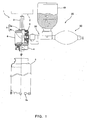
- Fig. 1 is an exterior view showing, partly in section, a water feed apparatus according to an embodiment of the present invention, and a core drill on which the water feed apparatus is mounted.
- the core drill 1 has a shank 3 that is supported at an upper portion thereof, via a chuck (not shown), on a drive shaft (not shown) of a drive mechanism 2 (indicated by a two-dotted line in Fig. 1 ).
- a cylindrical core body 5 is coupled via an attachment/detachment mechanism 4 to a lower portion of the shank 3, such that the shank 3 and the core body 5 are rotated integrally in conjunction with the rotation of the drive shaft of the drive mechanism 2. Furthermore, the core body 5 is provided at the lower circumferential end with cutting blades 5a for drilling a hole that are spaced in a circumferential direction at predetermined intervals.
- a cylindrical sleeve 6 is fitted over a central part in a longitudinal direction of the shank 3 such that the shank 3 is rotatably supported by the sleeve 6 via a bearing provided inside the sleeve 6.
- a throughhole is formed in a circumferential wall of the sleeve 6 to extend in a horizontal direction in Fig. 1 and communicate in and out of the sleeve 6, which throughhole constitutes a water feed apparatus mounting unit 8 for mounting a later-described water feed apparatus 20.
- a transverse hole 9a is formed in the shank 3 supported by the sleeve 6 to extend radially (horizontally in Fig. 1 ) through the shank 3.
- the transverse hole 9a is formed at a position corresponding to the water feed apparatus mounting unit 8 of the sleeve 6 and connected intermittently with the water feed apparatus mounting unit 8 during rotation of the shank 3.
- a vertical hole 9b is formed lengthwise and through a rotational center axis of the shank 3.
- the vertical hole 9b is connected at an upper end portion thereof to a longitudinally central position of the transverse hole 9a and communicates with the inside of the transverse hole 9a, and opens at a lower end portion thereof into an internal space of the core body 5.
- the transverse hole 9a and the vertical hole 9b as described above make up a cooling water passage 9 that guides the cooling water supplied from the water feed apparatus 20 to the core body 5.
- the water feed apparatus 20 which is coupled to the water feed apparatus mounting unit 8 of the sleeve 6, is mainly composed of an adapter 30, a water storage tank 40, and a pump unit 50. As shown in Fig. 1 , both the water storage tank 40 and the pump unit 50 are mounted on the adapter 30, and the coupling of the adapter 30 to the water feed apparatus mounting unit 8 completes the mounting of the water feed apparatus 20 to the core drill 1.
- Fig. 2 is an exploded view of the water feed apparatus 20, with a part of its structure shown in section.
- the adapter 30 is constructed from a first adapter 31 and a second adapter 32, the first adapter 31 being provided with an inductor cock 33.
- the first adapter 31 has a substantially pipe-shaped main body 31a, one end portion of which forms a drill-mounting portion 31b for coupling to the water feed apparatus mounting unit 8 of the sleeve 6 of the core drill 1.
- the other end portion of the main body 31a forms a joint 31c for coupling to the second adapter 32.
- the main body 31a of the first adapter 31 is internally formed with a first passage 31d that extends and connects between the drill-mounting portion 31b and the joint 31c.
- the first passage 31d is provided at a halfway point thereof with the inductor cock 33 as referred to above, which, when operated, opens and closes the first passage 31d while its open degree is adjusted.
- the second adapter 32 has a substantially pipe-shaped main body 32a, one end portion of which forms a joint 32b for coupling to the joint 31c of the first adapter 31.
- the other end portion of the main body 32a forms a pump mounting portion 32c for coupling the pump unit 50 thereto.
- the main body 32a of the second adapter 32 is internally formed with a second passage 32d that extends and connects between the joint 32b and the pump mounting portion 32c.
- the first adapter 31 and the second adapter 32 are coupled together by fitting the joint 31c of the first adapter 31 into the joint 32b of the second adapter 32 via a seal member (for example, O-ring) 25a.
- a seal member for example, O-ring
- a cylindrical tank mounting portion 34 is provided on top of the main body 32a of the second adapter 32 for mounting the water storage tank 40, and an internal space of the tank mounting portion 34 is connected with the second passage 32d.
- the path from the internal space of the tank mounting portion 34 through the second passage 32d of the second adapter 32 and the first passage 31d of the first adapter 31 to the drill-mounting portion 31b constitutes a water passage 37 for guiding cooling water from the water storage tank 40 to the core drill 1.
- the path from the pump mounting portion 32c of the second adapter 32 through the second passage 32d to the tank mounting portion 34 constitutes an air passage 38 that guides air from the pump unit 50 to the water storage tank 40.
- the cylindrical tank mounting portion 34 has an internal thread 34a threaded on an internal wall thereof.
- the water storage tank 40 shown in Fig. 2 is a commercially available plastic beverage bottle whose mouth is formed with an external thread 41a.
- the internal thread 34a of the tank mounting portion 34 is formed so as to screw on the external thread 41a of the water storage tank 40.
- the water storage tank 40 and the second adapter 32 are detachably coupled by screwing together their respective external thread 41a and internal thread 34a via a seal member (for example, packing) 25b disposed therebetween.
- the pump unit 50 has an air feed spherical body (gripper portion) 51 substantially of spherical shell shape (more specifically, substantially of elliptical contour as viewed from the side) that is made of a resilient material such as rubber.
- This air feed spherical body 51 is constructed so as to be relatively easily deformable by the grasping power of an operator, and its internal space 51a is enlargingly and reducingly deformed by a gripping operation of the operator.
- the air feed spherical body 51 is provided with two openings 52 and 53, and one end portion of a pipe-shaped first check valve body 52a is coupled to one opening 52 of these openings.
- the other end portion of the first check valve body 52a is coupled via a seal member (for example, O-ring) 25c to the pump mounting portion 32c of the second adapter 32, such that the internal space 51a of the air feed spherical body 51 is connected via the first check valve body 52a to the second passage 32d of the second adapter 32.
- the first check valve body 52a has a not-shown check valve mechanism incorporated therein that permits the flow of air only from the air feed spherical body 51 side to the second adapter 32 side and blocks the reverse direction flow of air (or water).
- One end portion of a pipe-shaped second check valve body 53a is coupled to the other opening 53 of the air feed spherical body 51.
- the other end portion of this second check valve body 53a opens to the outside such that the outside and the internal space 51a of the air feed spherical body 51 are communicated via the second check valve body 53a.
- the second check valve body 53a has a not-shown check valve mechanism incorporated therein that permits the flow of air only from the outside to the air feed spherical body 51 side and blocks the reverse direction flow of air (or water).
- the thus constructed water feed apparatus 20 is assembled to the core drill 1 by fitting the drill-mounting portion 31b of the first adapter 31 in the water feed apparatus mounting unit 8 of the sleeve 6 of the core drill 1.
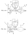
- the air feed spherical body 51 of the pump unit 50 is gripped for operation by an operator (see Fig. 4(a) ). In other words, gripping and loosening actions by hand of the air feed spherical body 51 are repeated several times by the operator. This allows the air, taken from the outside via the pump unit 50 into the adapter 30, to pass through the air passage 38 and be collected in the empty space (space not occupied by cooling water) inside the water storage tank 40, and to pressurize the air in that space.
- the first check valve body 52a acts to prevent any of the cooling water inside the water storage tank 40 from escaping back into the air feed spherical body 51.
- the gripping operation of the air feed spherical body 51 is stopped, and the inductor cock 33 is opened while adjusting its open degree (see Fig. 4(b) ).
- This allows cooling water, under the action of pressurized air, to be fed with a pressure from inside the water storage tank 40 through the water passage 37 to the core drill 1 side.
- the core drill 1 in the present embodiment is thus used with cooling water being fed, which cooling water is sent through the cooling water passage 9 to the cutting blades 5a at a lower portion of the core body 5, and cools same.
- the shank 3 and the core body 5 rotate at a high speed, but the water feed apparatus 20, being attached to the sleeve 6 that rotatably supports the shank 3, does not rotate with the shank 3.
- the water storage tank 40 and pump unit 50 formed to relatively small size are fixedly mounted via the adapter 30 on the core drill 1, an excellent portability is obtained. Furthermore, since cooling water inside the water storage tank 40 can be fed with a pressure to the core drill 1 through operation of the pump unit 50, supply of cooling water can appropriately be performed even at high-speed rotation of the shank 3.
- the construction illustrated is an example to which the present invention can preferably be applied, and the water feed apparatus of the present invention is not limited to such construction.
- a cylindrical gripper portion that is bellows-shaped at a circumferential portion thereof and closed at both ends, or yet another construction may be employed.
- a container other than a plastic beverage bottle may be used as the water storage tank 40, and may be constructed so as not to be detachable from the adapter 30.
- the water storage tank 40 can be provided with a water intake that is sealable.
- the water feed apparatus 60 shown in Fig. 5 includes an adapter 60a, and a pump unit 50 having the same construction as that already described.
- the adapter 60a is composed of a first adapter 61 of the same construction as the first adapter 31 of the adapter 30 employed in the already-described water feed apparatus 20, and a second adapter 62 of different construction from the second adapter 32.
- first adapter 61 of the same construction as the first adapter 31 of the adapter 30 employed in the already-described water feed apparatus 20
- a second adapter 62 of different construction from the second adapter 32 Incidentally, of the parts shown in Fig. 5 , those that have the same construction as already described in connection with Figs. 1 to 4 are given the same reference symbols, and their detailed description will be omitted.
- the second adapter 62 has a substantially pipe-shaped main body 62a, one end portion of which forms a joint 32b for coupling to a joint 31c of the first adapter 61, and the other end portion of which forms a pump mounting portion 32c where the pump unit 50 is coupled. Furthermore, a cylindrical tank mounting portion 34 for mounting the water storage tank 40 thereat is provided on the main body 62a between the joint 32b and the pump mounting portion 32c.
- a water passage 63 extends in the joint 32b along the center axis of the main body 62a and is bent at a halfway point to lead to the tank mounting portion 34.
- the water passage 63 opens at one end at the end portion of the joint 32b and opens at the other end to the internal space of the tank mounting portion 34.
- a pipe-like projection 63a extends inside the internal space of the tank mounting portion 34, in a direction from the inner bottom toward the opening of the tank mounting portion 34, and has an internal passage that forms the other end portion of the water passage 63.
- An air passage 64 also extends in the pump mounting portion 32c along the center axis of the main body 62a and is bent at a halfway point to lead to the tank mounting portion 34. The air passage 64 opens at one end at the end portion of the pump mounting portion 32c and opens at the other end at the inner bottom and toward the internal space of the tank mounting portion 34.
- the first adapter 61 and the second adapter 62 are coupled together by fitting the joint 31c of the first adapter 61 in the joint 32b of the second adapter 62 via a seal member 25a, and in this state, the first passage 31d of the first adapter 61 and the water passage 63 of the second adapter 62 are connected to each other.
- the first check valve body 52a of the pump unit 50 is coupled via a seal member 25c to the pump mounting portion 32c of the second adapter 62, and in this state, the internal space 51a of the air feed spherical body 51 of the pump unit 50 is connected to the air passage 64 of the second adapter 62.
- the air drawn from the outside into the air feed spherical body 51 is sent through the air passage 64, which is independent of the water passage 63, to the tank mounting portion 34, so as to be fed into the water storage tank 40 if the water storage tank 40 is being attached to the tank mounting portion 34.
- a flexible tube 70 is provided in the tank mounting portion 34 of the second adapter 62 for sending out water from inside the water storage tank 40 to the water passage 63.
- This tube 70 has a dimension equal to or slightly longer than the height dimension of the water storage tank 40, and has a proximal end portion thereof (portion downstream of water flow) fitted over and coupled to the pipe-like projection 63a provided inside the tank mounting portion 34 of the second adapter 62.
- the tube 70 is equipped at a distal end portion thereof (portion upstream of water flow) with a block-like sinker 72.
- the tube 70 is housed inside the water storage tank 40 when attaching the water storage tank 40 with water poured therein to the tank mounting portion 34 of the second adapter 62.
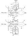
- Fig. 6(a) illustrates the state when drilling a hole downwards
- Fig. 6(b) illustrates the state when drilling a hole upwards.
- the water storage tank 40 is directed such that its mouth 41 is located on the lower side for the purpose of keeping the water storage tank 40 from interference with the surface to be drilled such as a concrete wall surface.
- the tube 70 inside the water storage tank 40 is caused to sink to the water bottom side (mouth 41 side of the water storage tank 40) by the gravitational weight of the sinker 72 equipped on the tube distal end portion.
- the tube 70 can take in water through its distal end portion and guide the water to the water passage 63 of the second adapter 62.
- the water storage tank 40 is directed such that its mouth 41 is located on the upper side for the purpose of avoiding interference between the surface to be drilled and the water storage tank 40.
- the tube 70 inside the water storage tank 40 is caused to sink to the water bottom side (bottom side of the water storage tank 40) by the gravitational weight of the sinker 72 equipped on the tube distal end portion.
- the tube 70 can take in water through its distal end portion and guide the water to the water passage 63.
- the distal end portion of the tube 70 is caused to be located on the water bottom side by the gravitational weight of the sinker 72, thereby enabling water to be taken in.
- water can be guided from inside the water storage tank 40 through the tube 70 to the water passage 63 and fed to the cutting blades 5a of the core body 5 (see Fig. 1 ), irrespective of the direction of drilling a hole and of the water storage tank 40.
- the present invention is not restricted to such construction.
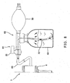
- a flexible water flow tube 80 made of silicon or the like may be used to couple between the first adapter 61 and the second adapter 62 as shown in Fig. 7 , instead of directly coupling them together.
- an upstream side end portion 80a of the water flow tube 80 may be coupled via another joint 81 to the joint 32b of the second adapter 62, and a downstream side end portion 80b of the water flow tube 80 may be coupled via yet another joint (not shown) to the joint 31c of the first adapter 61 according to need.
- the water feed apparatus 60 shown in Fig. 7 includes a carrying hook 82 for hanging the water storage tank 40 on a waist belt (not shown) or the like of an operator.
- a carrying hook 82 for hanging the water storage tank 40 on a waist belt (not shown) or the like of an operator.
- a plastic beverage bottle is used as the water storage tank 40
- a commercially available carrying hook for plastic bottles may be used for this carrying hook 82.
- drilling work of a hole in an object with the core drill 1 can be carried out with the water storage tank 40, the pump unit 50, and the second adapter 62 collectively hung on the waist belt or the like, resulting in improvement in convenience.
- the water storage tank 40 which weighs heavy, can be independently supported at a different region such as on the waist belt, thereby leading to an improved workability.
- the length dimension of the water flow tube 80 be approximately 1 to 1.5m from the viewpoint of not compromising the improvement in workability.
- the first adapter 61 and the second adapter 62 may be fixedly coupled, and a water flow tube 80 may be used to couple the first adapter 61 and the sleeve 6 of the core drill 1. Also in this case, an improvement in workability can be made, as with the water storage tank 60 of the construction shown in Fig. 7 .
- a water flow tube 80 may be used to couple between the second adapter 62 and the pump unit 50, or a construction may be adopted in which couplings shown in Figs. 7 to 9 are used in combination.
- the present invention is applied to a water feed apparatus for a wet-type core drill that drills a hole in concrete or the like.
- the present invention can preferably be applied as a water feed apparatus which does not require a large-sized water tank and improves the portability, and which makes it possible for cooling water to be easily compressed and thus for the core drill to be operated at high speeds.
Landscapes
- Engineering & Computer Science (AREA)
- Mechanical Engineering (AREA)
- Mining & Mineral Resources (AREA)
- Processing Of Stones Or Stones Resemblance Materials (AREA)
- Auxiliary Devices For Machine Tools (AREA)
- Drilling And Boring (AREA)
- Earth Drilling (AREA)
- Devices For Dispensing Beverages (AREA)
Claims (7)
- Wasserversorgungsvorrichtung (20; 60) für einen Nass-Kernbohrer (1), der ein Loch in ein zu bohrendes Objekt durch Drehen eines Kernkörpers (5) bohrt und der auf dem Kernkörper (5) vorgesehenen Schneidklingen (5a) Wasser zuführt, umfassend:einen Wasserspeicherbehälter (40), der Wasser zwecks Versorgung speichert;eine Pumpeneinheit (50), die Gas mit einem Druck dem Wasserspeicherbehälter (40) zuführt; undeinen Adapter (30; 60a), der den Wasserspeicherbehälter (40), die Pumpeneinheit (50) und den Kernbohrer (1) aneinanderkoppelt,wobei die Pumpeneinheit (50) einen Greiferabschnitt (51) aufweist, dessen Innenraum vergrößernd und verkleinernd verformbar ist durch eine greifende Betätigung seitens eines Bedieners, um das Gas dem Wasserspeicherbehälter (40) zuzuführen,wobei der Adapter (30; 60a) einen ersten Adapter (31; 61) mit einem Bohrerbefestigungsabschnitt (31 b) zur Befestigung auf dem Kernbohrer beinhaltet, und einen zweiten Adapter (32; 62) mit einem Behälterbefestigungsabschnitt (34), durch den der Wasserspeicherbehälter (40) lösbar am Adapter (30; 60a) befestigt ist, und mit einem Pumpenbefestigungsabschnitt (32c), durch den die Pumpeneinheit (50) am Adapter (30; 60a) befestigt ist,der erste Adapter (31; 61) und der zweite Adapter (32; 62) eine Wasserleitung (37; 63) beinhalten, die den Bohrerbefestigungsabschnitt (31 b) mit dem Behälterbefestigungsabschnitt (34) verbindet,dadurch gekennzeichnet, dass
der erste Adapter (31; 60a) eine Ventileinheit beinhaltet, die die Wasserleitung (37; 63) öffnet und schließt, und wobei
der zweite Adapter (32; 62) weiterhin eine Luftleitung (38; 64) beinhaltet, durch die der Behälterbefestigungsabschnitt (34) und der Pumpenbefestigungsabschnitt (32c) miteinander verbunden sind, und drehbar mit dem ersten Adapter (31; 61) verbunden ist, so dass eine Befestigungsrichtung des am Behälterbefestigungsabschnitt (34) befestigten Wasserspeicherbehälters (40) veränderbar ist. - Wasserversorgungsvorrichtung für den Kernbohrer nach Anspruch 1, wobei der Greiferabschnitt (51) der Pumpeneinheit (50) ein flexibles Teil mit im Wesentlichen der Form einer Kugelschale umfasst, das durch die greifende Betätigung seitens des Bedieners verformbar ist.
- Wasserversorgungsvorrichtung für den Kernbohrer nach Anspruch 1 oder 2, wobei die Pumpeneinheit (50) ein erstes Rückschlagventil umfasst, das Luft lediglich von außerhalb zum Innenraum (51a) des Greiferabschnitts (51) strömen lässt, und ein zweites Rückschlagventil, das Luft lediglich aus dem Innenraum (51a) des Greiferabschnitts (51) zur Wasserspeicherbehälterseite strömen lässt.
- Wasserversorgungsvorrichtung für den Kernbohrer nach Anspruch 1, wobei der Behälterbefestigungsabschnitt (34) des Adapters (30; 60a) mit einem Innengewinde ausgebildet ist, das so ausgelegt ist, dass es ein Hineinschrauben eines Außengewindes ermöglicht, das auf einer Kunststoffgetränkeflasche zum Aufschrauben einer Kappe ausgebildet ist.
- Wasserversorgungsvorrichtung für den Kernbohrer nach Anspruch 3 oder 4, wobei der Behälterbefestigungsabschnitt (34) so ausgelegt ist, dass auf ihm der Wasserspeicherbehälter (40), mit einem Wasserauslass desselben nach unten gerichtet, befestigt ist.
- Wasserversorgungsvorrichtung für den Kernbohrer nach einem der Ansprüche 3 bis 5, wobei eine flexible Röhre (70), zum Leiten von Wasser aus einem Inneren des Wasserspeicherbehälters (40) zur Wasserleitung (63), an einem Ende derselben an den Behälterbefestigungsabschnitt (34) des Adapters (60a) gekoppelt ist, und an einem entgegengesetzten Ende derselben mit einer Beschwerung (72) ausgestattet ist.
- Wasserversorgungsvorrichtung für den Kernbohrer nach Anspruch 6, wobei die Röhre (70) so ausgelegt ist, dass sich das entgegengesetzte Ende im Inneren des Wasserspeicherbehälters (40) durch eine Gewichtskraft der Beschwerung (72) abwärts befindet, unabhängig von einer Stellung des Wasserspeicherbehälters (40).
Applications Claiming Priority (3)
| Application Number | Priority Date | Filing Date | Title |
|---|---|---|---|
| JP2005004950 | 2005-01-12 | ||
| JP2005226636 | 2005-08-04 | ||
| PCT/JP2006/300074 WO2006075556A1 (ja) | 2005-01-12 | 2006-01-06 | コアドリル用の給水装置 |
Publications (3)
| Publication Number | Publication Date |
|---|---|
| EP1852233A1 EP1852233A1 (de) | 2007-11-07 |
| EP1852233A4 EP1852233A4 (de) | 2013-10-30 |
| EP1852233B1 true EP1852233B1 (de) | 2014-07-16 |
Family
ID=36677581
Family Applications (1)
| Application Number | Title | Priority Date | Filing Date |
|---|---|---|---|
| EP06711462.9A Expired - Lifetime EP1852233B1 (de) | 2005-01-12 | 2006-01-06 | Wasserversorgungsvorrichtung für einen kernbohrer |
Country Status (11)
| Country | Link |
|---|---|
| US (1) | US8419321B2 (de) |
| EP (1) | EP1852233B1 (de) |
| JP (1) | JP4903059B2 (de) |
| KR (1) | KR100903911B1 (de) |
| CN (1) | CN101102873B (de) |
| AU (1) | AU2006206137B9 (de) |
| BR (1) | BRPI0606196A2 (de) |
| CA (1) | CA2591964C (de) |
| ES (1) | ES2483566T3 (de) |
| RU (1) | RU2365499C2 (de) |
| WO (1) | WO2006075556A1 (de) |
Families Citing this family (7)
| Publication number | Priority date | Publication date | Assignee | Title |
|---|---|---|---|---|
| US8007348B2 (en) * | 2005-06-27 | 2011-08-30 | Husqvarna Professional Outdoor Products Inc. | Tools and methods for making and using tools, blades and methods of making and using blades, and machines for working on work pieces |
| JP4951725B2 (ja) * | 2008-12-29 | 2012-06-13 | 西條 達哉 | ハンドドリル用ドリルビット冷却器 |
| WO2012003393A2 (en) * | 2010-07-01 | 2012-01-05 | Jeff Hardin | Hand-held water drill |
| CA2829513A1 (en) | 2011-05-30 | 2012-12-06 | Kabushiki Kaisha Miyanaga | Coolant supply device and electric drill unit provided with coolant supply device |
| TWI510335B (zh) * | 2014-02-21 | 2015-12-01 | wei lin Tu | 用於鑽孔機的給水連接器 |
| US9815162B1 (en) * | 2016-03-23 | 2017-11-14 | Climb Tech, Llc | Method and apparatus for providing cutting fluid in a CNC machine |
| GB201813828D0 (en) * | 2018-08-24 | 2018-10-10 | Worton Ian Geoffrey | Dispensing head and dispenser |
Family Cites Families (28)
| Publication number | Priority date | Publication date | Assignee | Title |
|---|---|---|---|---|
| US3547350A (en) * | 1968-12-16 | 1970-12-15 | Mc Donnell Douglas Corp | Spraying device |
| US3577808A (en) * | 1968-12-23 | 1971-05-04 | Boeing Co | Sub-zero cutting fluid generator |
| GB2060442B (en) * | 1979-10-02 | 1983-03-02 | Aslen D E | Coolant feed device |
| ATE10711T1 (de) * | 1979-11-19 | 1984-12-15 | Imperial Chemical Industries Plc | Elektrostatischer spruehapparat. |
| US4775296A (en) | 1981-12-28 | 1988-10-04 | United Technologies Corporation | Coolable airfoil for a rotary machine |
| JPS58117303U (ja) * | 1982-02-04 | 1983-08-10 | 株式会社ミヤナガ | 給油装置付きドリルスタンド |
| SU1126390A1 (ru) * | 1982-12-20 | 1984-11-30 | Минское специальное конструкторское бюро протяжных станков | Устройство дл подвода смазочно-охлаждающей жидкости (сож) |
| JPS6038271A (ja) | 1983-08-12 | 1985-02-27 | Secoh Giken Inc | 走行モ−ドを変更できる自走車 |
| JPS6038271U (ja) * | 1983-08-20 | 1985-03-16 | 原 基浩 | 液供給容器 |
| JPH083904B2 (ja) | 1987-02-12 | 1996-01-17 | 三菱電機株式会社 | 半導体レ−ザ−駆動回路 |
| JPH0518032Y2 (de) | 1987-06-10 | 1993-05-13 | ||
| CN2039741U (zh) * | 1988-10-24 | 1989-06-21 | 杜丹彤 | 便携式空心钻 |
| JPH0338311A (ja) * | 1989-07-04 | 1991-02-19 | K F C:Kk | コンクリート等の穿孔方法 |
| JP3061283B2 (ja) | 1990-04-28 | 2000-07-10 | 三洋電機株式会社 | ビデオディスクの製造方法 |
| JPH0413246U (de) * | 1990-05-24 | 1992-02-03 | ||
| JP3257602B2 (ja) * | 1992-03-04 | 2002-02-18 | ラサ工業株式会社 | ノンコアドリル |
| JP3131636B2 (ja) * | 1992-05-11 | 2001-02-05 | 芝浦電産株式会社 | 電気ドリル |
| JPH06219459A (ja) * | 1993-01-25 | 1994-08-09 | O K Kikaku Kenkyusho:Kk | 液体噴出器 |
| RU2058474C1 (ru) * | 1993-08-10 | 1996-04-20 | Специальное конструкторское бюро по геологоразведочной технике | Способ бурения скважины |
| US5419661A (en) * | 1994-07-25 | 1995-05-30 | Kennametal Inc. | Rotatable tooholder having a stationary, through-center coolant feed system |
| GB9425224D0 (en) * | 1994-12-14 | 1995-02-08 | Bristol Tool Gauge | Adaptor |
| US5669743A (en) * | 1995-07-14 | 1997-09-23 | Tapmatic Corporation | Fluid dispensing and control system for tapping attachments |
| JPH11128789A (ja) * | 1997-10-31 | 1999-05-18 | Sanyo Electric Co Ltd | 携帯型噴霧装置及び噴霧器 |
| US6371332B1 (en) * | 1999-07-13 | 2002-04-16 | Albert H. Fox | Apparatus for producing foam from liquid mixture |
| JP3410417B2 (ja) * | 2000-02-25 | 2003-05-26 | 千森産業株式会社 | ボトルを装着可能な水鉄砲 |
| JP3556599B2 (ja) * | 2001-01-29 | 2004-08-18 | 株式会社 ダイアック | コアドリル |
| JP2002326218A (ja) * | 2001-05-07 | 2002-11-12 | Misumi Tokushu:Kk | コア・ドリル用循環切削水処理装置 |
| JP3629016B2 (ja) | 2002-07-02 | 2005-03-16 | 株式会社ミヤナガ | コアドリル |
-
2006
- 2006-01-06 JP JP2006552898A patent/JP4903059B2/ja not_active Expired - Fee Related
- 2006-01-06 KR KR1020077018122A patent/KR100903911B1/ko not_active Expired - Fee Related
- 2006-01-06 WO PCT/JP2006/300074 patent/WO2006075556A1/ja not_active Ceased
- 2006-01-06 US US11/813,670 patent/US8419321B2/en not_active Expired - Fee Related
- 2006-01-06 CA CA002591964A patent/CA2591964C/en not_active Expired - Fee Related
- 2006-01-06 ES ES06711462.9T patent/ES2483566T3/es not_active Expired - Lifetime
- 2006-01-06 CN CN2006800021482A patent/CN101102873B/zh not_active Expired - Fee Related
- 2006-01-06 RU RU2007130723/03A patent/RU2365499C2/ru not_active IP Right Cessation
- 2006-01-06 BR BRPI0606196-6A patent/BRPI0606196A2/pt not_active IP Right Cessation
- 2006-01-06 AU AU2006206137A patent/AU2006206137B9/en not_active Ceased
- 2006-01-06 EP EP06711462.9A patent/EP1852233B1/de not_active Expired - Lifetime
Also Published As
| Publication number | Publication date |
|---|---|
| CN101102873A (zh) | 2008-01-09 |
| AU2006206137B2 (en) | 2008-12-18 |
| CA2591964A1 (en) | 2006-07-20 |
| EP1852233A4 (de) | 2013-10-30 |
| KR100903911B1 (ko) | 2009-06-19 |
| CN101102873B (zh) | 2010-12-01 |
| HK1107794A1 (en) | 2008-04-18 |
| BRPI0606196A2 (pt) | 2009-06-02 |
| RU2365499C2 (ru) | 2009-08-27 |
| US20090129878A1 (en) | 2009-05-21 |
| AU2006206137A1 (en) | 2006-07-20 |
| JPWO2006075556A1 (ja) | 2008-06-12 |
| KR20070103434A (ko) | 2007-10-23 |
| WO2006075556A1 (ja) | 2006-07-20 |
| AU2006206137B9 (en) | 2009-05-21 |
| CA2591964C (en) | 2010-03-09 |
| JP4903059B2 (ja) | 2012-03-21 |
| ES2483566T3 (es) | 2014-08-06 |
| RU2007130723A (ru) | 2009-02-20 |
| AU2006206137B8 (en) | 2009-01-08 |
| US8419321B2 (en) | 2013-04-16 |
| EP1852233A1 (de) | 2007-11-07 |
Similar Documents
| Publication | Publication Date | Title |
|---|---|---|
| CA2591964C (en) | Water feed apparatus for core drill | |
| US20080201877A1 (en) | Hand-held cleaning/polishing machine | |
| KR20130075779A (ko) | 냉각액 공급 장치 및 그 냉각액 공급 장치를 구비한 전동 드릴 유닛 | |
| SE467347B (sv) | Sjaelvcentrerande anordning foer slipning av haardmetallstift paa borrkronor | |
| NO344515B1 (no) | Frem- og tilbakegående kompressor eller pumpe og et flyttbart verktøykraftsystem innbefattet en frem- og tilbakegående kompressor | |
| US20210394997A1 (en) | Mixing apparatus, method of making the mixing apparatus and using the mixing apparatus | |
| JP7711061B2 (ja) | 注入装置 | |
| JP5331318B2 (ja) | 内視鏡装置 | |
| EP1480735B1 (de) | Abgedichteter propeller zum erzeugen von metallschaum und dazugehörendes system | |
| HK1107794B (en) | Water supply device for core drill | |
| WO2001075342A1 (en) | Dosing device | |
| JP2009045318A (ja) | ミシン | |
| CN217100674U (zh) | 一种下料装置及包装机 | |
| CN218135450U (zh) | 一种焊管除毛刺装置 | |
| CN213310227U (zh) | 一种可旋转加压的骨水泥装载装置 | |
| CN215082370U (zh) | 一种重症病人喂药器 | |
| CA2114299A1 (en) | Drive apparatuses, called "contra-angles", for rotary instruments used in bone surgery, especially in dental surgery | |
| CN218310996U (zh) | 一种手持式气动钻机 | |
| CN110102798A (zh) | 带有水冷却系统的手电钻 | |
| CN111017313A (zh) | 袋装机及基于该袋装机的灌装方法 | |
| JP3780491B2 (ja) | 掘削機におけるスイベル装置 | |
| US298483A (en) | Dental hand-piece | |
| JP2003311577A (ja) | 洗浄具 | |
| ITPD20090166A1 (it) | Dispositivo di aspirazione e raccolta della polvere prodotta da trapani | |
| JPH09193048A (ja) | ラインオイラ |
Legal Events
| Date | Code | Title | Description |
|---|---|---|---|
| PUAI | Public reference made under article 153(3) epc to a published international application that has entered the european phase |
Free format text: ORIGINAL CODE: 0009012 |
|
| 17P | Request for examination filed |
Effective date: 20070625 |
|
| AK | Designated contracting states |
Kind code of ref document: A1 Designated state(s): AT BE BG CH CY CZ DE DK EE ES FI FR GB GR HU IE IS IT LI LT LU LV MC NL PL PT RO SE SI SK TR |
|
| DAX | Request for extension of the european patent (deleted) | ||
| A4 | Supplementary search report drawn up and despatched |
Effective date: 20130927 |
|
| RIC1 | Information provided on ipc code assigned before grant |
Ipc: B28D 1/14 20060101ALI20130923BHEP Ipc: B28D 7/02 20060101AFI20130923BHEP |
|
| GRAP | Despatch of communication of intention to grant a patent |
Free format text: ORIGINAL CODE: EPIDOSNIGR1 |
|
| INTG | Intention to grant announced |
Effective date: 20140415 |
|
| GRAS | Grant fee paid |
Free format text: ORIGINAL CODE: EPIDOSNIGR3 |
|
| GRAA | (expected) grant |
Free format text: ORIGINAL CODE: 0009210 |
|
| AK | Designated contracting states |
Kind code of ref document: B1 Designated state(s): AT BE BG CH CY CZ DE DK EE ES FI FR GB GR HU IE IS IT LI LT LU LV MC NL PL PT RO SE SI SK TR |
|
| REG | Reference to a national code |
Ref country code: GB Ref legal event code: FG4D |
|
| REG | Reference to a national code |
Ref country code: CH Ref legal event code: EP |
|
| REG | Reference to a national code |
Ref country code: ES Ref legal event code: FG2A Ref document number: 2483566 Country of ref document: ES Kind code of ref document: T3 Effective date: 20140806 |
|
| REG | Reference to a national code |
Ref country code: IE Ref legal event code: FG4D |
|
| REG | Reference to a national code |
Ref country code: AT Ref legal event code: REF Ref document number: 677316 Country of ref document: AT Kind code of ref document: T Effective date: 20140815 |
|
| REG | Reference to a national code |
Ref country code: DE Ref legal event code: R096 Ref document number: 602006042271 Country of ref document: DE Effective date: 20140821 |
|
| REG | Reference to a national code |
Ref country code: NL Ref legal event code: VDEP Effective date: 20140716 |
|
| REG | Reference to a national code |
Ref country code: AT Ref legal event code: MK05 Ref document number: 677316 Country of ref document: AT Kind code of ref document: T Effective date: 20140716 |
|
| REG | Reference to a national code |
Ref country code: LT Ref legal event code: MG4D |
|
| PG25 | Lapsed in a contracting state [announced via postgrant information from national office to epo] |
Ref country code: LT Free format text: LAPSE BECAUSE OF FAILURE TO SUBMIT A TRANSLATION OF THE DESCRIPTION OR TO PAY THE FEE WITHIN THE PRESCRIBED TIME-LIMIT Effective date: 20140716 Ref country code: PT Free format text: LAPSE BECAUSE OF FAILURE TO SUBMIT A TRANSLATION OF THE DESCRIPTION OR TO PAY THE FEE WITHIN THE PRESCRIBED TIME-LIMIT Effective date: 20141117 Ref country code: GR Free format text: LAPSE BECAUSE OF FAILURE TO SUBMIT A TRANSLATION OF THE DESCRIPTION OR TO PAY THE FEE WITHIN THE PRESCRIBED TIME-LIMIT Effective date: 20141017 Ref country code: FI Free format text: LAPSE BECAUSE OF FAILURE TO SUBMIT A TRANSLATION OF THE DESCRIPTION OR TO PAY THE FEE WITHIN THE PRESCRIBED TIME-LIMIT Effective date: 20140716 Ref country code: BG Free format text: LAPSE BECAUSE OF FAILURE TO SUBMIT A TRANSLATION OF THE DESCRIPTION OR TO PAY THE FEE WITHIN THE PRESCRIBED TIME-LIMIT Effective date: 20141016 Ref country code: SE Free format text: LAPSE BECAUSE OF FAILURE TO SUBMIT A TRANSLATION OF THE DESCRIPTION OR TO PAY THE FEE WITHIN THE PRESCRIBED TIME-LIMIT Effective date: 20140716 |
|
| PG25 | Lapsed in a contracting state [announced via postgrant information from national office to epo] |
Ref country code: IS Free format text: LAPSE BECAUSE OF FAILURE TO SUBMIT A TRANSLATION OF THE DESCRIPTION OR TO PAY THE FEE WITHIN THE PRESCRIBED TIME-LIMIT Effective date: 20141116 Ref country code: NL Free format text: LAPSE BECAUSE OF FAILURE TO SUBMIT A TRANSLATION OF THE DESCRIPTION OR TO PAY THE FEE WITHIN THE PRESCRIBED TIME-LIMIT Effective date: 20140716 Ref country code: AT Free format text: LAPSE BECAUSE OF FAILURE TO SUBMIT A TRANSLATION OF THE DESCRIPTION OR TO PAY THE FEE WITHIN THE PRESCRIBED TIME-LIMIT Effective date: 20140716 Ref country code: PL Free format text: LAPSE BECAUSE OF FAILURE TO SUBMIT A TRANSLATION OF THE DESCRIPTION OR TO PAY THE FEE WITHIN THE PRESCRIBED TIME-LIMIT Effective date: 20140716 Ref country code: CY Free format text: LAPSE BECAUSE OF FAILURE TO SUBMIT A TRANSLATION OF THE DESCRIPTION OR TO PAY THE FEE WITHIN THE PRESCRIBED TIME-LIMIT Effective date: 20140716 Ref country code: LV Free format text: LAPSE BECAUSE OF FAILURE TO SUBMIT A TRANSLATION OF THE DESCRIPTION OR TO PAY THE FEE WITHIN THE PRESCRIBED TIME-LIMIT Effective date: 20140716 |
|
| REG | Reference to a national code |
Ref country code: DE Ref legal event code: R097 Ref document number: 602006042271 Country of ref document: DE |
|
| PG25 | Lapsed in a contracting state [announced via postgrant information from national office to epo] |
Ref country code: SK Free format text: LAPSE BECAUSE OF FAILURE TO SUBMIT A TRANSLATION OF THE DESCRIPTION OR TO PAY THE FEE WITHIN THE PRESCRIBED TIME-LIMIT Effective date: 20140716 Ref country code: RO Free format text: LAPSE BECAUSE OF FAILURE TO SUBMIT A TRANSLATION OF THE DESCRIPTION OR TO PAY THE FEE WITHIN THE PRESCRIBED TIME-LIMIT Effective date: 20140716 Ref country code: EE Free format text: LAPSE BECAUSE OF FAILURE TO SUBMIT A TRANSLATION OF THE DESCRIPTION OR TO PAY THE FEE WITHIN THE PRESCRIBED TIME-LIMIT Effective date: 20140716 Ref country code: DK Free format text: LAPSE BECAUSE OF FAILURE TO SUBMIT A TRANSLATION OF THE DESCRIPTION OR TO PAY THE FEE WITHIN THE PRESCRIBED TIME-LIMIT Effective date: 20140716 Ref country code: CZ Free format text: LAPSE BECAUSE OF FAILURE TO SUBMIT A TRANSLATION OF THE DESCRIPTION OR TO PAY THE FEE WITHIN THE PRESCRIBED TIME-LIMIT Effective date: 20140716 |
|
| PLBE | No opposition filed within time limit |
Free format text: ORIGINAL CODE: 0009261 |
|
| STAA | Information on the status of an ep patent application or granted ep patent |
Free format text: STATUS: NO OPPOSITION FILED WITHIN TIME LIMIT |
|
| 26N | No opposition filed |
Effective date: 20150417 |
|
| PG25 | Lapsed in a contracting state [announced via postgrant information from national office to epo] |
Ref country code: BE Free format text: LAPSE BECAUSE OF NON-PAYMENT OF DUE FEES Effective date: 20150131 |
|
| REG | Reference to a national code |
Ref country code: CH Ref legal event code: PL |
|
| PG25 | Lapsed in a contracting state [announced via postgrant information from national office to epo] |
Ref country code: LU Free format text: LAPSE BECAUSE OF FAILURE TO SUBMIT A TRANSLATION OF THE DESCRIPTION OR TO PAY THE FEE WITHIN THE PRESCRIBED TIME-LIMIT Effective date: 20150106 |
|
| PG25 | Lapsed in a contracting state [announced via postgrant information from national office to epo] |
Ref country code: MC Free format text: LAPSE BECAUSE OF FAILURE TO SUBMIT A TRANSLATION OF THE DESCRIPTION OR TO PAY THE FEE WITHIN THE PRESCRIBED TIME-LIMIT Effective date: 20140716 |
|
| PG25 | Lapsed in a contracting state [announced via postgrant information from national office to epo] |
Ref country code: LI Free format text: LAPSE BECAUSE OF NON-PAYMENT OF DUE FEES Effective date: 20150131 Ref country code: CH Free format text: LAPSE BECAUSE OF NON-PAYMENT OF DUE FEES Effective date: 20150131 |
|
| REG | Reference to a national code |
Ref country code: IE Ref legal event code: MM4A |
|
| PG25 | Lapsed in a contracting state [announced via postgrant information from national office to epo] |
Ref country code: SI Free format text: LAPSE BECAUSE OF FAILURE TO SUBMIT A TRANSLATION OF THE DESCRIPTION OR TO PAY THE FEE WITHIN THE PRESCRIBED TIME-LIMIT Effective date: 20140716 |
|
| REG | Reference to a national code |
Ref country code: FR Ref legal event code: PLFP Year of fee payment: 11 |
|
| PG25 | Lapsed in a contracting state [announced via postgrant information from national office to epo] |
Ref country code: IE Free format text: LAPSE BECAUSE OF NON-PAYMENT OF DUE FEES Effective date: 20150106 |
|
| PG25 | Lapsed in a contracting state [announced via postgrant information from national office to epo] |
Ref country code: BE Free format text: LAPSE BECAUSE OF FAILURE TO SUBMIT A TRANSLATION OF THE DESCRIPTION OR TO PAY THE FEE WITHIN THE PRESCRIBED TIME-LIMIT Effective date: 20140716 |
|
| REG | Reference to a national code |
Ref country code: FR Ref legal event code: PLFP Year of fee payment: 12 |
|
| PG25 | Lapsed in a contracting state [announced via postgrant information from national office to epo] |
Ref country code: HU Free format text: LAPSE BECAUSE OF FAILURE TO SUBMIT A TRANSLATION OF THE DESCRIPTION OR TO PAY THE FEE WITHIN THE PRESCRIBED TIME-LIMIT; INVALID AB INITIO Effective date: 20060106 |
|
| PG25 | Lapsed in a contracting state [announced via postgrant information from national office to epo] |
Ref country code: TR Free format text: LAPSE BECAUSE OF FAILURE TO SUBMIT A TRANSLATION OF THE DESCRIPTION OR TO PAY THE FEE WITHIN THE PRESCRIBED TIME-LIMIT Effective date: 20140716 |
|
| REG | Reference to a national code |
Ref country code: FR Ref legal event code: PLFP Year of fee payment: 13 |
|
| PGFP | Annual fee paid to national office [announced via postgrant information from national office to epo] |
Ref country code: FR Payment date: 20230113 Year of fee payment: 18 Ref country code: ES Payment date: 20230201 Year of fee payment: 18 |
|
| PGFP | Annual fee paid to national office [announced via postgrant information from national office to epo] |
Ref country code: IT Payment date: 20230130 Year of fee payment: 18 Ref country code: GB Payment date: 20230120 Year of fee payment: 18 Ref country code: DE Payment date: 20230123 Year of fee payment: 18 |
|
| REG | Reference to a national code |
Ref country code: DE Ref legal event code: R119 Ref document number: 602006042271 Country of ref document: DE |
|
| GBPC | Gb: european patent ceased through non-payment of renewal fee |
Effective date: 20240106 |
|
| PG25 | Lapsed in a contracting state [announced via postgrant information from national office to epo] |
Ref country code: DE Free format text: LAPSE BECAUSE OF NON-PAYMENT OF DUE FEES Effective date: 20240801 |
|
| PG25 | Lapsed in a contracting state [announced via postgrant information from national office to epo] |
Ref country code: GB Free format text: LAPSE BECAUSE OF NON-PAYMENT OF DUE FEES Effective date: 20240106 |
|
| PG25 | Lapsed in a contracting state [announced via postgrant information from national office to epo] |
Ref country code: FR Free format text: LAPSE BECAUSE OF NON-PAYMENT OF DUE FEES Effective date: 20240131 |
|
| PG25 | Lapsed in a contracting state [announced via postgrant information from national office to epo] |
Ref country code: GB Free format text: LAPSE BECAUSE OF NON-PAYMENT OF DUE FEES Effective date: 20240106 Ref country code: FR Free format text: LAPSE BECAUSE OF NON-PAYMENT OF DUE FEES Effective date: 20240131 Ref country code: DE Free format text: LAPSE BECAUSE OF NON-PAYMENT OF DUE FEES Effective date: 20240801 |
|
| PG25 | Lapsed in a contracting state [announced via postgrant information from national office to epo] |
Ref country code: IT Free format text: LAPSE BECAUSE OF NON-PAYMENT OF DUE FEES Effective date: 20240106 |
|
| REG | Reference to a national code |
Ref country code: ES Ref legal event code: FD2A Effective date: 20250226 |
|
| PG25 | Lapsed in a contracting state [announced via postgrant information from national office to epo] |
Ref country code: ES Free format text: LAPSE BECAUSE OF NON-PAYMENT OF DUE FEES Effective date: 20240107 |