EP1852072B1 - Guide d'alignement - Google Patents
Guide d'alignement Download PDFInfo
- Publication number
- EP1852072B1 EP1852072B1 EP07114343A EP07114343A EP1852072B1 EP 1852072 B1 EP1852072 B1 EP 1852072B1 EP 07114343 A EP07114343 A EP 07114343A EP 07114343 A EP07114343 A EP 07114343A EP 1852072 B1 EP1852072 B1 EP 1852072B1
- Authority
- EP
- European Patent Office
- Prior art keywords
- alignment guide
- guide according
- jaw
- jaws
- alignment
- Prior art date
- Legal status (The legal status is an assumption and is not a legal conclusion. Google has not performed a legal analysis and makes no representation as to the accuracy of the status listed.)
- Not-in-force
Links
Images


Classifications
-
- A—HUMAN NECESSITIES
- A61—MEDICAL OR VETERINARY SCIENCE; HYGIENE
- A61B—DIAGNOSIS; SURGERY; IDENTIFICATION
- A61B17/00—Surgical instruments, devices or methods, e.g. tourniquets
- A61B17/16—Bone cutting, breaking or removal means other than saws, e.g. Osteoclasts; Drills or chisels for bones; Trepans
- A61B17/17—Guides or aligning means for drills, mills, pins or wires
- A61B17/1739—Guides or aligning means for drills, mills, pins or wires specially adapted for particular parts of the body
- A61B17/1742—Guides or aligning means for drills, mills, pins or wires specially adapted for particular parts of the body for the hip
- A61B17/175—Guides or aligning means for drills, mills, pins or wires specially adapted for particular parts of the body for the hip for preparing the femur for hip prosthesis insertion
-
- A—HUMAN NECESSITIES
- A61—MEDICAL OR VETERINARY SCIENCE; HYGIENE
- A61B—DIAGNOSIS; SURGERY; IDENTIFICATION
- A61B17/00—Surgical instruments, devices or methods, e.g. tourniquets
- A61B17/14—Surgical saws ; Accessories therefor
- A61B17/15—Guides therefor
Definitions
- the present invention relates to a tool for use in hip resurfacing operations. More particularly, it relates to a head alignment tool.
- Each hip joint is comprised by the upper portion of the upper leg bone (femur) which terminates in an offset bony neck surmounted by a ball-headed portion which rotates within a socket, known as the acetabulum, in the pelvis.
- Diseases such as rheumatoid- and osteo-arthritis can cause erosion of the cartilage lining of the acetabulum so that the ball of the femur and the hip bone rub together causing pain and further erosion.
- Bone erosion may cause the bones themselves to attempt to compensate for the erosion which may result in the bone being reshaped. This misshapen joint may cause pain and may eventually cease to function altogether.
- the hip prosthesis will be formed of two components, namely: an acetabular, or socket, component which lines the acetabulum; and a femoral, or stem, component which replaces the femoral head.
- an acetabular, or socket component which lines the acetabulum
- a femoral, or stem component which replaces the femoral head.
- the acetabular component can then be inserted into place.
- the acetabular component may simply be held in place by a tight fit with the bone.
- additional fixing means such as screws or bone cement may be used.
- the acetabular component may be coated on its external surface with a bone growth promoting substance which will assist the bone to grow and thereby assist the holding of the acetabular component in place.
- the bone femoral head will be removed and the femur hollowed using reamers and rasps to accept the prosthesis.
- the stem portion will then be inserted into the femur.
- a femoral component of the kind described above may be replaced with components for use in femoral head resurfacing or for use in thrust plate technology.
- the requirement for the surgeon to obtain the necessary access to the hip joint means that it is necessary to make a large incision on one side of the hip.
- a straight incision is made through the skin on the posterior edge of the greater trochanter. In some techniques this incision may be made when the hip is flexed to 45°.
- the muscles and tendons are parted and held by various retractors such that they do not interfere with the surgeons access to the hip joint. The hip is then dislocated to provide access to the head of the femur.
- the surgeon inserts a pin in the lateral femur.
- the desired position of the pin will be known from pre-operative analysis of the x-rays.
- the surgeon will measure the desired distance down the femur from the tip of the greater trochanter and the alignment pin is inserted through the vastus lateralis fibres.
- the alignment pin is inserted in a transverse direction into the mid-lateral cortex and directed upwardly towards the femoral head.
- the pin is left protruding so that an alignment guide can be hooked over the alignment pin.
- Suitable alignment guides include those known as the McMinn Alignment Guide available from Midland Medical Technologies Ltd.
- Prior art alignment guides of the kind described above generally comprise a hook or aperture which is placed over the alignment pin thus providing a good angular position for the axis of the implant in valgus, varus and ante-version of the neck.
- the guide will then be adjusted such that a cannulated rod is located such that the aperture therein is directed down the mid-lateral axis of the femoral neck.
- a stylus having been set to the desired femoral component size is positioned such that it can be passed around the femoral neck. When the stylus can be passed around the femoral neck, the cannulated rod is locked in position.
- a guide wire can then be inserted though the cannulated rod.
- This guide wire is then used in the further surgery in which the femoral head is shaped to accept the prosthesis.
- the alignment guide is an essential tool in the surgical procedure to ensure that the aperture drilled in the femoral head is both central to the femoral neck and at the correct angle of alignment to the femoral neck and that the shaping of the femoral head is accurate for the chosen head size.
- US4896663 describes a hand-held drill jig which may be utilised to locate and maintain a central access through a head and associated neck of a femur enabling a hole to be drilled into the femoral head orientated to the central axis.
- the drill jig is adjustable to accommodate a broad range of sizes of femurs and can be readily attached to, and then removed from, the femur.
- a positioning mechanism is provided to engage the outer, peripheral surface of the femoral head and the head-neck junction.
- the alignment guide facilitates the accuracy and ease of use of the instruments that work from the neck.
- an alignment guide for use in femoral head surgery comprising:
- the alignment guide is configured such that in use the jaws in the first open position may be passed over the head of the femur and in the second clamping position will clamp against the neck of the femur.
- the two jaws will preferably each be movable by the operation of a screw means. Whilst each jaw may have a dedicated screw means, in a preferred arrangement the jaws will be mutually connected at their proximal ends via a screw member having two oppositely threaded ends, each threaded end being associated with a jaw such that when the screw is rotated in one direction the jaws will move towards the center of the screw to the clamped position and when it is rotated in the other direction the jaws move apart to the open position. It will be understood that in this arrangement, the jaws remain parallel during the movement between the open and the clamped position.
- the screw means having two oppositely threaded ends will be connected to the support member by any suitable arrangement.
- the center portion of the screw member which may be unthreaded, will pass through a receiving portion of the support member.
- the screw means will preferably include a head to facilitate the operation of the screw means by the operator.
- the jaws may be connected to the support member by pivot arms.
- the jaws may be curved along at least a part of their length such that in use they can extend around the head of the femur and their distal ends can be clamped to the neck of the femur.
- a portion of the length will be substantially straight and in this arrangement, a portion, towards the end of the jaws, remote from the support member will be angled to allow the distal ends to clamp to the neck of the femur.
- the tool will preferably be configured such that one jaw is particularly suitable for clamping to the inferior part of the neck (i.e. the underside) and can therefore be referred to as the inferior jaw, and the other is particularly suitable for clamping to the superior part of the neck (i.e. the topside) and can therefore be referred to as the superior jaw.
- the two jaws may be of the same or different configurations.
- Biting elements may be located on one or both jaws to improve the clamping of the jaw with the neck of the femur.
- the biting element on the superior jaw may be of any suitable arrangement but is preferably a T-bar located at or near the distal end of the jaw. In use the T-bar will come into contact with the superior part of the neck.
- the T-bar is preferably cylindrical.
- the inferior jaw may be longer than the superior jaw.
- the inferior jaw may extend in length over the superior jaw to provide a flag to assist the surgeon to visually ensure that the tool is in the required position. This distal portion of the inferior jaw may be substantially straight.
- the toothed block may have a concave face between the teeth.
- the teeth will preferably be configured and spaced on the block such that in use they interact with the inferior part of the neck of the femur to cause the tool to be angled at the optimum position.
- the teeth will enable the tool to be clamped at the correct anteversion angle and at the correct angle from the sagittal plane with these angles being fixed by the femur itself. It is generally believed that there is a portion of the inferior femoral neck located from the head/neck junction of the femur to a position about 2 cms from the head/neck junction which is parallel to the optimum angle for the positioning of the stem of the prosthesis and hence this is often used as an alignment reference.
- the optimum position of the tool may be achieved with four teeth in a generally square configuration.
- the teeth are preferably spaced at from about 10 to about 25 mm apart. They are most preferably spaced at about 15 mm.
- the length of the inferior jaw, or the positioning of the block on the inferior jaw are selected such that the teeth interact with the portion of the femoral neck detailed above.
- the correct axis for insertion of the guide wire into the head of the femur is approximately 30 degrees from the sagittal plane and in 20 degrees anteversion.
- the jaws and biting elements are configured such that in use the cannulated rod will be located such that a guide wire is inserted at the correct angle.
- the tool will automatically take the correct orientation from the medial neck.
- the cannulated rod is adjustable with respect to the support member.
- the rod is a sliding fit in the support arm. Once in the required position the cannulated rod will preferably be lockable such that once locked further movement is prevented.
- the locking means may be of any suitable arrangement. In one arrangement, a locking screw may be used.
- the cannulated rod will in use enable the surgeon to position the guide wire.
- the cannulated rod may have a slot extending along at least a part of the length of the rod to assist in removing the tool from the guide wire once it is in position.
- the cannulated rod will preferably have teeth located at the distal end thereof which in use can be driven into the surface of the femoral head. When driven into the head, these teeth help to clamp the alignment tool in position and to stabilise the tool.
- the cannulated rod may additionally function as a measuring or gauging device and to assist this the surface of the rod may include measuring indica to assist the surgeon to know how deep they have cut.
- An alignment rod support may be included on the support arm which may support one or more alignment rods which in use will provide a visual guide to assist the surgeon to check that the tool is in the correct position.
- the or each alignment rod which may be of any suitable arrangement, may be fitted into the alignment rod support by any suitable arrangement.
- One or more apertures may be included in the alignment rod support through which a portion of the alignment rod may be passed.
- the alignment rod may be a guidewire.
- the tool of the present invention may additionally include stylus means of the kind known in the prior art.
- the correct axis for insertion of the guide wire into the head of the femur is approximately 30 degrees from the sagittal plane and in 20 degrees of anteversion.
- the tool of the present invention is configured such that in use the cannulated bore will be located such that the guide wire is inserted at the correct angle.
- the arrangement of the present invention allows the surgeon to visually check that the tool is in the correct orientation.
- the surgeon will shape the head of the femur to fit within the cavity of the resurfacing prosthesis. This generally involves a number of shaping steps including the removal of the dome of the femoral head by means of a saw. It is important that the saw cut is made in the correct position so that an accurate fit with the prosthesis can be achieved.
- the position of the cut to remove the dome of the femoral head can be calculated from the top of the dome of the femoral head.
- a saw cutting guide may be located on the cannulated rod such that when the rod is in position, the guide will illustrate the correct position for the cut.
- Separate guides may be provided for each head size of resurfacing head prosthesis.
- a saw cutting guide may be located on at least one of the jaws.
- the alignment guide of the present invention may be used in combination with an elongate distal alignment guide which is described in more detail below.
- the alignment guide of the present invention may be used in a method of preparing the head of a femur for femoral head resurfacing wherein the method comprises:
- a well may be drilled into the head of the femur via the collar or rod.
- This well may be the definite hole diameter required of approximately 8 mm and drilled to a depth determined by the tube touching the head.
- a check may be made with a stylus once the tool is removed and cylinder cutters used guided over a peg placed in the well. These cutters are arranged such that the diameter cut will be correct for the head size chosen and will bottom on the top of the cut head such that the teeth of the cutter do not dangerously over-sail the head-neck junction and cause soft tissue damage or neck notching.
- the method preferably comprises:
- the correct axis for insertion of the guide wire into the head of the femur is approximately 30 degrees from the sagittal plane axis of the femur and in anteversion to allow for the natural offset in each position.
- the tool of the present invention is configured such that in use the cannulated bore will be located such that the guide wire or drill is inserted at the correct angle.
- the arrangement of the present invention allows the surgeon to place, and to visually check that the tool is in the correct orientation, and position centered on the femoral head-neck junction.
- the tool of the present invention may be used with all sizes of resurfacing head.
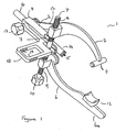
- the alignment guide 1 of one embodiment of the present invention comprises a support arm 2 having a distal end 3 and a proximal end 4.
- a superior jaw 5 and an inferior jaw 6 are attached to a screw means 7 which comprises a screw member have two oppositely threaded ends 8 and 9 and a head 10.
- a screw means 7 which comprises a screw member have two oppositely threaded ends 8 and 9 and a head 10.
- the jaws of this embodiment are curved along at least a part of their length.
- the inferior jaw 6 is longer than the superior jaw 5 to form a flag 6a which is straight.
- the biting means on the superior jaw 5 is a cylindrical T-bar 11 which is located at the end of the jaw and perpendicular thereto.
- the biting means on the inferior jaw 6 is a toothed block 12 which is located on the straight portion of the jaw.
- the jaws are additionally connected to the support means 2 by pivot arms 13.
- the cannulated rod 16 is a sliding fit in a sleeve in the support means.
- a locking screw 17 will enable the user to lock the cannulated rod at the required position.
- a bore will extend through the rod. Teeth 15 are located on the face of the bore.
- a flag holder 18 having apertures 19 through which a flag such as a guide wire may be passed.
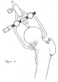
- the tool of the first embodiment of the present invention in the clamped position on the neck of a femur is illustrated schematically in Figure 2 .
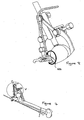
- the alignment tool 1 of this second embodiment of the present invention comprises a support arm 2' having a distal end 3' and a proximal end 4 ⁇ .
- a superior jaw 5' and a inferior jaw 6' are attached to the screw means 7' which comprises a screw member having two oppositely threaded ends 8' and 9' and a head 10.
- the screw means 7' which comprises a screw member having two oppositely threaded ends 8' and 9' and a head 10.
- the jaws of this embodiment are substantially straight along at least a part of their length and are then angled such that in use their ends can interact with the neck of a femur.
- a flag corresponding to 6a in the embodiment of Figure 1 is not present.
- the arrangement of Figure 3 could readily be adjusted to include the flag if required.
- the biting means on the superior jaw 5' is a cylindrical T -bar 11' which is located at the end of the jaw and perpendicular thereto.
- the biting means on the inferior jaw 6' is a toothed block 12'.
- the teeth are located about 15 mm apart and as illustrated in Figure 4 interact with the substantially straight portion of the inferior part of the neck of the femur.
- the jaws are additionally connected to the support means 2' by pivot arms 13'.
- the cannulated rod 16' which may include a collar 20' is a sliding fit in a sleeve in the support means.
- a locking screw 17' will enable the user to lock the cannulated rod at the required position.
- a ball will extend through the rod. Teeth 15' are located on the face of the ball.
- a flag holder 18' which in this embodiment is arranged to hold up to two guide wires is provided.
- the flag holder 18' has apertures 19' through which a flag such as a guide wire 21' may be passed.
- the alignment guide of the present invention may be used in combination with an elongate distal alignment guide 120.
- the elongate distal alignment guide 120 is illustrated in Figures 5 to 8 .
- the elongate distal alignment guide is used to suggest an optimum femoral component angle for the resurfacing head implant.
- the aligmnent guide of the present invention suggests an angle for insertion of the guide wire and ultimately the final implanted femoral resurfacing head prosthesis, relative to the leg alignment axis.
- the leg alignment axis is a theoretical line between the centre of the femoral head, middle of the knee and middle of the ankle when the person is standing. The axis can be measured easily between the femoral head and knee on a patient in surgery.
- the position of the axis and the femoral component angle are illustrated in Figure 5 .
- the elongate distal alignment guide may be attached to the alignment guide of the present invention or it may be a separate component which may be connectable to the alignment guide of the present invention or separate therefrom. Where it is separate, it will touch on the elongate guide of the present invention to measure the current femoral component angle.
- the elongate alignment guide will generally comprise a long rod 121 slidable in a collar 122 so that its length can be adjusted.
- a locking nut 123 will be provided to lock the rod at the desired length.
- a stop 124 may be provided at the end of the rod which in use will come into contact with the back of the patient's knee to protect the skin.
- Arms 125, 126 extend from the collar 122 and enable the rod to be either fixed to the alignment guide of the present invention or impinge therewith. Arm 126 may be referred to as a probe arm.
- the angle between the rod 121 and the probe arm 126 may be fixed or it may be adjustable. An adjustable arrangement is illustrated in more detail in Figures 7 and 8 .
- the "+” sign implies that the alignment guide of the present invention needs to be placed more in valgus and the "-” implies that it needs to be placed in more varus.
- the area shown hatched in Figure 8 is the area that is free to rotate on the shaft until it touches on the alignment guide of the present invention.
- the "+/-" display may be placed with a display showing degrees.
- the spiked end 127 should be placed at the centre of the femoral head as this represents the start of the leg alignment axis.
- elongate distal alignment guide described above may be used with any alignment guide of the present invention or any other alignment guide.
Landscapes
- Health & Medical Sciences (AREA)
- Surgery (AREA)
- Life Sciences & Earth Sciences (AREA)
- Medical Informatics (AREA)
- Animal Behavior & Ethology (AREA)
- Orthopedic Medicine & Surgery (AREA)
- Oral & Maxillofacial Surgery (AREA)
- Engineering & Computer Science (AREA)
- Biomedical Technology (AREA)
- Heart & Thoracic Surgery (AREA)
- Dentistry (AREA)
- Molecular Biology (AREA)
- Nuclear Medicine, Radiotherapy & Molecular Imaging (AREA)
- General Health & Medical Sciences (AREA)
- Public Health (AREA)
- Veterinary Medicine (AREA)
- Surgical Instruments (AREA)
- Prostheses (AREA)
- Optical Couplings Of Light Guides (AREA)
- Valve-Gear Or Valve Arrangements (AREA)
- Magnetic Heads (AREA)
Claims (22)
- Dispositif de guidage d'alignement (1) à des fins d'utilisation dans le cadre d'une intervention chirurgicale au niveau de la tête fémorale comportant :un bras de support (2) ;une tige tubulaire (16) supportée par le bras de support (2), et pouvant être ajustée par rapport à celui-ci, etdeux mâchoires, une mâchoire supérieure (5) et une mâchoire inférieure (6), chaque mâchoire ayant une extrémité proximale connectée au bras de support (2), et une extrémité distale destinée à serrer le col du fémur en cours d'utilisation ; au moins l'une desdites mâchoires étant mobile d'une première position ouverte à une deuxième position de serrage ;dans lequel un bloc denté (12) est situé sur la mâchoire inférieure (6) en tant qu'élément grippant sur la mâchoire inférieure (6) pour améliorer, en cours d'utilisation, le serrage de la mâchoire par rapport au col du fémur, caractérisé en ce que le bloc denté (12) comporte quatre dents en une configuration carrée.
- Dispositif de guidage d'alignement selon la revendication 1, dans lequel les deux mâchoires (5, 6) sont mobiles de la première position ouverte à une deuxième position de serrage.
- Dispositif de guidage d'alignement selon la revendication 1 ou la revendication 2, dans lequel les mâchoires (5, 6) restent parallèles alors qu'elles se déplacent de la première position ouverte à la deuxième position de serrage.
- Dispositif de guidage d'alignement selon l'une quelconque des revendications 1 à 3, dans lequel les mâchoires (5, 6) sont mobiles par le biais d'un moyen de type vis (7).
- Dispositif de d'alignement selon la revendication 4, dans lequel les mâchoires (5, 6) sont mutuellement connectées au niveau de leurs extrémités distales par le biais d'un organe de type vis (7) ayant deux extrémités filetées dans des contraire (8, 9).
- Dispositif de guidage d'alignement selon la revendication 5, dans lequel la partie centrale de l'organe de type vis passe au travers d'une partie réceptrice de l'organe de support.
- Dispositif de guidage d'alignement selon la revendication 6, dans lequel la partie centrale de la vis est non filetée.
- Dispositif de guidage d'alignement selon l'une quelconque des revendications 5 à 7, dans lequel le moyen de type vis (7) comprend une tête (10) destinée à faciliter la rotation du moyen de type vis.
- Dispositif de guidage d'alignement selon l'une quelconque des revendications 1 à 8, dans lequel les mâchoires (5, 6) sont connectées à l'organe de type bras de support (2) par des bras de pivot (13).
- Dispositif de guidage d'alignement selon l'une quelconque des revendications 1 à 9, dans lequel les mâchoires (5, 6) sont courbées le long d'au moins une partie de leur longueur.
- Dispositif de guidage d'alignement selon l'une quelconque des revendications 1 à 9, dans lequel les mâchoires (5, 6) sont droites le long d'au moins une partie de leur longueur.
- Dispositif de guidage d'alignement selon l'une quelconque des revendications 1 à 11, dans lequel les deux mâchoires (5, 6) sont de configurations différentes.
- Dispositif de guidage d'alignement selon l'une quelconque des revendications 1 à 12, dans lequel un élément grippant est également situé sur la mâchoire supérieure (5) améliorer, en cours d'utilisation, le serrage de la mâchoire par rapport au col du fémur.
- Dispositif do guidage d'alignement selon la revendication 13, lequel l'élément grippant sur la mâchoire supérieure (5) est une barre en T (11) as niveau de l'extrémité distale de la mâchoire ou à proximité de celle-ci.
- Dispositif de guidage d'alignement selon l'une quelconque des revendications 1 à 4, dans lequel le bloc (12) a une face concave entre les dents.
- Dispositif de guidage d'alignement selon l'une quelconque des revendications 1 à 15, dans lequel les dents sont séparées d'une distance d'environ 15 mm.
- Dispositif de guidage d'alignement selon l'une quelconque des revendications 1 à 16, dans lequel la tige tubulaire (16) est en mesure d'être ajustée par rapport au bras de support (2).
- Dispositif de guidage d'alignement selon la revendication 17, dans lequel la tige (16) est à ajustement glissant dans le bras de support (2).
- Dispositif de guidage d'alignement selon la revendication 17 ou la revendication 18, dans lequel le dispositif de guidage comprend par ailleurs (17) un moyen destiné à verrouiller la tige tubulaire par rapport à l'organe de support.
- Dispositif de guidage d'alignement selon l'une quelconque des revendications 1 à 19, dans lequel le dispositif de guidage d'alignement comprend par ailleurs un dispositif de guidage de coupe pour scie.
- Dispositif de guidage d'alignement selon l'une quelconque des revendications 1 à 20, dans lequel le dispositif de guidage d'alignement comprend par ailleurs un porte-indicateur (18).
- Kit comportant le dispositif de guidage d'alignement selon l'une quelconque des revendications 1 à 21 et un dispositif de guidage d'alignement distal allongé (20) qui en référençant l'arrière du genou permettra de référencer l'axe d'alignement de la jambe.
Applications Claiming Priority (3)
| Application Number | Priority Date | Filing Date | Title |
|---|---|---|---|
| GBGB0408793.8A GB0408793D0 (en) | 2004-04-20 | 2004-04-20 | Tool |
| GB0419640A GB0419640D0 (en) | 2004-09-03 | 2004-09-03 | tool |
| EP05252477A EP1588669B1 (fr) | 2004-04-20 | 2005-04-20 | Guide d'alignement |
Related Parent Applications (1)
| Application Number | Title | Priority Date | Filing Date |
|---|---|---|---|
| EP05252477A Division EP1588669B1 (fr) | 2004-04-20 | 2005-04-20 | Guide d'alignement |
Publications (3)
| Publication Number | Publication Date |
|---|---|
| EP1852072A2 EP1852072A2 (fr) | 2007-11-07 |
| EP1852072A3 EP1852072A3 (fr) | 2007-11-14 |
| EP1852072B1 true EP1852072B1 (fr) | 2009-04-15 |
Family
ID=34940946
Family Applications (2)
| Application Number | Title | Priority Date | Filing Date |
|---|---|---|---|
| EP07114343A Not-in-force EP1852072B1 (fr) | 2004-04-20 | 2005-04-20 | Guide d'alignement |
| EP05252477A Not-in-force EP1588669B1 (fr) | 2004-04-20 | 2005-04-20 | Guide d'alignement |
Family Applications After (1)
| Application Number | Title | Priority Date | Filing Date |
|---|---|---|---|
| EP05252477A Not-in-force EP1588669B1 (fr) | 2004-04-20 | 2005-04-20 | Guide d'alignement |
Country Status (4)
| Country | Link |
|---|---|
| US (2) | US20050245936A1 (fr) |
| EP (2) | EP1852072B1 (fr) |
| AT (2) | ATE371410T1 (fr) |
| DE (2) | DE602005002175T2 (fr) |
Families Citing this family (150)
| Publication number | Priority date | Publication date | Assignee | Title |
|---|---|---|---|---|
| US6695883B2 (en) * | 2002-04-11 | 2004-02-24 | Theodore W. Crofford | Femoral neck fixation prosthesis |
| US8801720B2 (en) | 2002-05-15 | 2014-08-12 | Otismed Corporation | Total joint arthroplasty system |
| GB0322084D0 (en) * | 2003-09-22 | 2003-10-22 | Depuy Int Ltd | A drill guide assembly |
| US7699847B2 (en) * | 2003-11-20 | 2010-04-20 | Wright Medical Technology, Inc. | Guide clamp for guiding placement of a guide wire in a femur |
| US20050245934A1 (en) * | 2004-03-09 | 2005-11-03 | Finsbury (Development) Limited | Tool |
| ATE371410T1 (de) * | 2004-04-20 | 2007-09-15 | Finsbury Dev Ltd | Ausrichtungsführung |
| GB0411487D0 (en) * | 2004-05-22 | 2004-06-23 | Depuy Int Ltd | Surgical jig |
| GB0505782D0 (en) * | 2005-03-22 | 2005-04-27 | Depuy Int Ltd | Surgical guide |
| CN101277651B (zh) | 2005-08-31 | 2010-08-25 | 齐默有限公司 | 移植器 |
| EP1772106A1 (fr) * | 2005-10-06 | 2007-04-11 | Zimmer GmbH | Instrument pour préparer et/ou travailler la tête du fémur |
| GB0521173D0 (en) * | 2005-10-18 | 2005-11-23 | Finsbury Dev Ltd | Tool |
| CA2640759A1 (fr) | 2005-11-09 | 2007-05-18 | Zimmer Gmbh | Implant |
| GB0525637D0 (en) * | 2005-12-16 | 2006-01-25 | Finsbury Dev Ltd | Tool |
| GB0601803D0 (en) * | 2006-01-30 | 2006-03-08 | Finsbury Dev Ltd | Tool |
| WO2007097853A2 (fr) | 2006-02-15 | 2007-08-30 | Otismed Corp | Dispositifs d'arthroplastie et procédés correspondants |
| US9808262B2 (en) | 2006-02-15 | 2017-11-07 | Howmedica Osteonics Corporation | Arthroplasty devices and related methods |
| US10278711B2 (en) | 2006-02-27 | 2019-05-07 | Biomet Manufacturing, Llc | Patient-specific femoral guide |
| US8591516B2 (en) | 2006-02-27 | 2013-11-26 | Biomet Manufacturing, Llc | Patient-specific orthopedic instruments |
| US8241293B2 (en) | 2006-02-27 | 2012-08-14 | Biomet Manufacturing Corp. | Patient specific high tibia osteotomy |
| US8858561B2 (en) * | 2006-06-09 | 2014-10-14 | Blomet Manufacturing, LLC | Patient-specific alignment guide |
| US9173661B2 (en) | 2006-02-27 | 2015-11-03 | Biomet Manufacturing, Llc | Patient specific alignment guide with cutting surface and laser indicator |
| US8133234B2 (en) | 2006-02-27 | 2012-03-13 | Biomet Manufacturing Corp. | Patient specific acetabular guide and method |
| US9345548B2 (en) | 2006-02-27 | 2016-05-24 | Biomet Manufacturing, Llc | Patient-specific pre-operative planning |
| US20150335438A1 (en) | 2006-02-27 | 2015-11-26 | Biomet Manufacturing, Llc. | Patient-specific augments |
| US7967868B2 (en) | 2007-04-17 | 2011-06-28 | Biomet Manufacturing Corp. | Patient-modified implant and associated method |
| US8070752B2 (en) | 2006-02-27 | 2011-12-06 | Biomet Manufacturing Corp. | Patient specific alignment guide and inter-operative adjustment |
| US8282646B2 (en) | 2006-02-27 | 2012-10-09 | Biomet Manufacturing Corp. | Patient specific knee alignment guide and associated method |
| US8603180B2 (en) | 2006-02-27 | 2013-12-10 | Biomet Manufacturing, Llc | Patient-specific acetabular alignment guides |
| US8535387B2 (en) | 2006-02-27 | 2013-09-17 | Biomet Manufacturing, Llc | Patient-specific tools and implants |
| US8407067B2 (en) | 2007-04-17 | 2013-03-26 | Biomet Manufacturing Corp. | Method and apparatus for manufacturing an implant |
| US9289253B2 (en) | 2006-02-27 | 2016-03-22 | Biomet Manufacturing, Llc | Patient-specific shoulder guide |
| US8473305B2 (en) | 2007-04-17 | 2013-06-25 | Biomet Manufacturing Corp. | Method and apparatus for manufacturing an implant |
| US8568487B2 (en) | 2006-02-27 | 2013-10-29 | Biomet Manufacturing, Llc | Patient-specific hip joint devices |
| US8092465B2 (en) | 2006-06-09 | 2012-01-10 | Biomet Manufacturing Corp. | Patient specific knee alignment guide and associated method |
| US8298237B2 (en) | 2006-06-09 | 2012-10-30 | Biomet Manufacturing Corp. | Patient-specific alignment guide for multiple incisions |
| US8377066B2 (en) | 2006-02-27 | 2013-02-19 | Biomet Manufacturing Corp. | Patient-specific elbow guides and associated methods |
| US8864769B2 (en) | 2006-02-27 | 2014-10-21 | Biomet Manufacturing, Llc | Alignment guides with patient-specific anchoring elements |
| US9339278B2 (en) | 2006-02-27 | 2016-05-17 | Biomet Manufacturing, Llc | Patient-specific acetabular guides and associated instruments |
| US9113971B2 (en) | 2006-02-27 | 2015-08-25 | Biomet Manufacturing, Llc | Femoral acetabular impingement guide |
| US9918740B2 (en) | 2006-02-27 | 2018-03-20 | Biomet Manufacturing, Llc | Backup surgical instrument system and method |
| US9907659B2 (en) | 2007-04-17 | 2018-03-06 | Biomet Manufacturing, Llc | Method and apparatus for manufacturing an implant |
| US8608749B2 (en) | 2006-02-27 | 2013-12-17 | Biomet Manufacturing, Llc | Patient-specific acetabular guides and associated instruments |
| US8608748B2 (en) | 2006-02-27 | 2013-12-17 | Biomet Manufacturing, Llc | Patient specific guides |
| WO2007125060A1 (fr) | 2006-04-28 | 2007-11-08 | Zimmer Gmbh | Implant |
| WO2007137327A1 (fr) * | 2006-05-26 | 2007-12-06 | Ellysian Ltd | Pièce de serrage pour le resurfaçage de la hanche |
| US20070299451A1 (en) * | 2006-06-08 | 2007-12-27 | Howmedica Osteonics Corp. | Offset tool guide for femoral head preparation |
| US9795399B2 (en) | 2006-06-09 | 2017-10-24 | Biomet Manufacturing, Llc | Patient-specific knee alignment guide and associated method |
| JP4736091B2 (ja) * | 2006-06-30 | 2011-07-27 | オリンパステルモバイオマテリアル株式会社 | 骨切術用開大器 |
| US7805853B2 (en) * | 2006-08-31 | 2010-10-05 | David H Littig | Transfemoral pelvic impression system |
| GB2442441B (en) * | 2006-10-03 | 2011-11-09 | Biomet Uk Ltd | Surgical instrument |
| US7828752B2 (en) * | 2006-10-05 | 2010-11-09 | Arthroplasty Innovations, Llc | Device and method for locating the anteroposterior femoral axis to determine proper femoral component rotation in knee replacement |
| US20080109085A1 (en) * | 2006-11-03 | 2008-05-08 | Howmedica Osteonics Corp. | Method and apparatus for hip femoral resurfacing tooling |
| GB2444330A (en) * | 2006-12-02 | 2008-06-04 | Sanjay Valmikrao Sonanis | Femoral neck head centering device |
| NZ577340A (en) * | 2006-12-15 | 2011-09-30 | Synthes Gmbh | Osteotomy guide, typically for medial distal tibia, with fixations points and guide member for engaging separated portions of bone |
| US8460302B2 (en) | 2006-12-18 | 2013-06-11 | Otismed Corporation | Arthroplasty devices and related methods |
| WO2008089347A2 (fr) * | 2007-01-17 | 2008-07-24 | Verban Emil M Jr | Tampon à limites destiné aux implants dentaires |
| WO2008098307A1 (fr) * | 2007-02-15 | 2008-08-21 | Robert Lye | Pince chirurgicale pour os |
| GB0712247D0 (en) * | 2007-06-25 | 2007-08-01 | I J Smith & Nephew Ltd | Medical device |
| WO2009018128A2 (fr) | 2007-07-31 | 2009-02-05 | Zimmer, Inc. | Dispositif prothétique d'interposition dans l'espace d'articulation avec des surfaces d'appui internes |
| GB0718418D0 (en) | 2007-09-21 | 2007-10-31 | Depuy Int Ltd | Adjustable surgical instrument |
| GB0718416D0 (en) | 2007-09-21 | 2007-10-31 | Depuy Int Ltd | Surgical instrument attachment |
| US8265949B2 (en) | 2007-09-27 | 2012-09-11 | Depuy Products, Inc. | Customized patient surgical plan |
| ES2838598T3 (es) | 2007-09-30 | 2021-07-02 | Depuy Products Inc | Instrumento quirúrgico ortopédico personalizado y específico del paciente |
| US8357111B2 (en) | 2007-09-30 | 2013-01-22 | Depuy Products, Inc. | Method and system for designing patient-specific orthopaedic surgical instruments |
| US8460303B2 (en) | 2007-10-25 | 2013-06-11 | Otismed Corporation | Arthroplasty systems and devices, and related methods |
| USD642263S1 (en) | 2007-10-25 | 2011-07-26 | Otismed Corporation | Arthroplasty jig blank |
| US10582934B2 (en) | 2007-11-27 | 2020-03-10 | Howmedica Osteonics Corporation | Generating MRI images usable for the creation of 3D bone models employed to make customized arthroplasty jigs |
| US8221430B2 (en) | 2007-12-18 | 2012-07-17 | Otismed Corporation | System and method for manufacturing arthroplasty jigs |
| US8545509B2 (en) | 2007-12-18 | 2013-10-01 | Otismed Corporation | Arthroplasty system and related methods |
| US8160345B2 (en) | 2008-04-30 | 2012-04-17 | Otismed Corporation | System and method for image segmentation in generating computer models of a joint to undergo arthroplasty |
| US8777875B2 (en) | 2008-07-23 | 2014-07-15 | Otismed Corporation | System and method for manufacturing arthroplasty jigs having improved mating accuracy |
| US8737700B2 (en) | 2007-12-18 | 2014-05-27 | Otismed Corporation | Preoperatively planning an arthroplasty procedure and generating a corresponding patient specific arthroplasty resection guide |
| US8480679B2 (en) | 2008-04-29 | 2013-07-09 | Otismed Corporation | Generation of a computerized bone model representative of a pre-degenerated state and useable in the design and manufacture of arthroplasty devices |
| US8715291B2 (en) | 2007-12-18 | 2014-05-06 | Otismed Corporation | Arthroplasty system and related methods |
| US8311306B2 (en) | 2008-04-30 | 2012-11-13 | Otismed Corporation | System and method for image segmentation in generating computer models of a joint to undergo arthroplasty |
| US8617171B2 (en) | 2007-12-18 | 2013-12-31 | Otismed Corporation | Preoperatively planning an arthroplasty procedure and generating a corresponding patient specific arthroplasty resection guide |
| GB0802402D0 (en) * | 2008-02-08 | 2008-03-12 | Smith & Nephew Orthopaedics Gm | Medical device and method |
| GB0803041D0 (en) * | 2008-02-20 | 2008-03-26 | Depuy Int Ltd | Surgical instrument |
| US9408618B2 (en) | 2008-02-29 | 2016-08-09 | Howmedica Osteonics Corporation | Total hip replacement surgical guide tool |
| US8617175B2 (en) | 2008-12-16 | 2013-12-31 | Otismed Corporation | Unicompartmental customized arthroplasty cutting jigs and methods of making the same |
| GB0822078D0 (en) | 2008-12-03 | 2009-01-07 | Finsbury Dev Ltd | Tool |
| US8170641B2 (en) | 2009-02-20 | 2012-05-01 | Biomet Manufacturing Corp. | Method of imaging an extremity of a patient |
| CN102802543B (zh) * | 2009-05-07 | 2015-06-17 | 史密夫和内修有限公司 | 用于近端股骨的病人专用对线引导装置 |
| US8414591B2 (en) * | 2009-07-17 | 2013-04-09 | Materialise N.V. | Surgical guiding tool, methods for manufacture and uses thereof |
| DE102009028503B4 (de) | 2009-08-13 | 2013-11-14 | Biomet Manufacturing Corp. | Resektionsschablone zur Resektion von Knochen, Verfahren zur Herstellung einer solchen Resektionsschablone und Operationsset zur Durchführung von Kniegelenk-Operationen |
| GB201001573D0 (en) | 2010-02-01 | 2010-03-17 | Univ Antwerpen | Method and device for endoscopically assisted arthroplasty |
| US8632547B2 (en) | 2010-02-26 | 2014-01-21 | Biomet Sports Medicine, Llc | Patient-specific osteotomy devices and methods |
| US9066727B2 (en) | 2010-03-04 | 2015-06-30 | Materialise Nv | Patient-specific computed tomography guides |
| AU2011245143B2 (en) | 2010-04-30 | 2016-07-07 | Smith & Nephew, Inc. | Guide for drilling an irregular-shaped body |
| WO2012021849A2 (fr) * | 2010-08-13 | 2012-02-16 | Smith & Nephew, Inc. | Guide sur mesure |
| US9271744B2 (en) | 2010-09-29 | 2016-03-01 | Biomet Manufacturing, Llc | Patient-specific guide for partial acetabular socket replacement |
| FR2967047B1 (fr) * | 2010-11-05 | 2013-09-20 | Aston Medical | Gabarit de pose d'une prothese d'epaule sur une glene |
| US9968376B2 (en) | 2010-11-29 | 2018-05-15 | Biomet Manufacturing, Llc | Patient-specific orthopedic instruments |
| US9241745B2 (en) | 2011-03-07 | 2016-01-26 | Biomet Manufacturing, Llc | Patient-specific femoral version guide |
| CN102119869B (zh) * | 2011-03-21 | 2012-11-14 | 潍坊航维医疗器械有限公司 | 股骨颈专用钻孔定位器 |
| US8715289B2 (en) | 2011-04-15 | 2014-05-06 | Biomet Manufacturing, Llc | Patient-specific numerically controlled instrument |
| US9675400B2 (en) | 2011-04-19 | 2017-06-13 | Biomet Manufacturing, Llc | Patient-specific fracture fixation instrumentation and method |
| US8668700B2 (en) | 2011-04-29 | 2014-03-11 | Biomet Manufacturing, Llc | Patient-specific convertible guides |
| US8956364B2 (en) | 2011-04-29 | 2015-02-17 | Biomet Manufacturing, Llc | Patient-specific partial knee guides and other instruments |
| US8926661B2 (en) | 2011-06-02 | 2015-01-06 | Smith & Nephew, Inc. | Surgical fastening |
| US8532807B2 (en) | 2011-06-06 | 2013-09-10 | Biomet Manufacturing, Llc | Pre-operative planning and manufacturing method for orthopedic procedure |
| US9084618B2 (en) | 2011-06-13 | 2015-07-21 | Biomet Manufacturing, Llc | Drill guides for confirming alignment of patient-specific alignment guides |
| US8764760B2 (en) | 2011-07-01 | 2014-07-01 | Biomet Manufacturing, Llc | Patient-specific bone-cutting guidance instruments and methods |
| US20130001121A1 (en) | 2011-07-01 | 2013-01-03 | Biomet Manufacturing Corp. | Backup kit for a patient-specific arthroplasty kit assembly |
| US9044812B2 (en) | 2011-08-03 | 2015-06-02 | General Electric Company | Jig and method for modifying casing in turbine system |
| US8597365B2 (en) | 2011-08-04 | 2013-12-03 | Biomet Manufacturing, Llc | Patient-specific pelvic implants for acetabular reconstruction |
| US9066734B2 (en) | 2011-08-31 | 2015-06-30 | Biomet Manufacturing, Llc | Patient-specific sacroiliac guides and associated methods |
| US9295497B2 (en) | 2011-08-31 | 2016-03-29 | Biomet Manufacturing, Llc | Patient-specific sacroiliac and pedicle guides |
| US20130245632A1 (en) * | 2011-09-13 | 2013-09-19 | The Cleveland Clinic Foundation | Method and apparatus for insertion of an elongate pin into a surface |
| US9386993B2 (en) | 2011-09-29 | 2016-07-12 | Biomet Manufacturing, Llc | Patient-specific femoroacetabular impingement instruments and methods |
| US9451973B2 (en) | 2011-10-27 | 2016-09-27 | Biomet Manufacturing, Llc | Patient specific glenoid guide |
| US9301812B2 (en) | 2011-10-27 | 2016-04-05 | Biomet Manufacturing, Llc | Methods for patient-specific shoulder arthroplasty |
| KR20130046336A (ko) | 2011-10-27 | 2013-05-07 | 삼성전자주식회사 | 디스플레이장치의 멀티뷰 디바이스 및 그 제어방법과, 디스플레이 시스템 |
| EP2770918B1 (fr) | 2011-10-27 | 2017-07-19 | Biomet Manufacturing, LLC | Guides glénoïdes spécifiques d'un patient |
| US9554910B2 (en) | 2011-10-27 | 2017-01-31 | Biomet Manufacturing, Llc | Patient-specific glenoid guide and implants |
| US9261549B2 (en) * | 2011-12-28 | 2016-02-16 | Electric Power Research Institute, Inc. | Leakage current sensor for suspension type insulator |
| US9237950B2 (en) | 2012-02-02 | 2016-01-19 | Biomet Manufacturing, Llc | Implant with patient-specific porous structure |
| US9402637B2 (en) | 2012-10-11 | 2016-08-02 | Howmedica Osteonics Corporation | Customized arthroplasty cutting guides and surgical methods using the same |
| US9204977B2 (en) | 2012-12-11 | 2015-12-08 | Biomet Manufacturing, Llc | Patient-specific acetabular guide for anterior approach |
| US9060788B2 (en) | 2012-12-11 | 2015-06-23 | Biomet Manufacturing, Llc | Patient-specific acetabular guide for anterior approach |
| US9839438B2 (en) | 2013-03-11 | 2017-12-12 | Biomet Manufacturing, Llc | Patient-specific glenoid guide with a reusable guide holder |
| US9579107B2 (en) | 2013-03-12 | 2017-02-28 | Biomet Manufacturing, Llc | Multi-point fit for patient specific guide |
| US9498233B2 (en) | 2013-03-13 | 2016-11-22 | Biomet Manufacturing, Llc. | Universal acetabular guide and associated hardware |
| US9826981B2 (en) | 2013-03-13 | 2017-11-28 | Biomet Manufacturing, Llc | Tangential fit of patient-specific guides |
| US9517145B2 (en) | 2013-03-15 | 2016-12-13 | Biomet Manufacturing, Llc | Guide alignment system and method |
| AU2014228420B2 (en) | 2013-03-15 | 2018-11-08 | Smith & Nephew, Inc. | Surgical fastening |
| US20150112349A1 (en) | 2013-10-21 | 2015-04-23 | Biomet Manufacturing, Llc | Ligament Guide Registration |
| GB2521630B (en) * | 2013-12-23 | 2015-11-18 | Daniel J Sanders | A precision surical guidance tool system and method for implementing dental implants |
| US10123813B2 (en) | 2014-02-17 | 2018-11-13 | Smith & Nephew, Inc. | Drill guide |
| US10282488B2 (en) | 2014-04-25 | 2019-05-07 | Biomet Manufacturing, Llc | HTO guide with optional guided ACL/PCL tunnels |
| US9408616B2 (en) | 2014-05-12 | 2016-08-09 | Biomet Manufacturing, Llc | Humeral cut guide |
| US9561040B2 (en) | 2014-06-03 | 2017-02-07 | Biomet Manufacturing, Llc | Patient-specific glenoid depth control |
| US9839436B2 (en) | 2014-06-03 | 2017-12-12 | Biomet Manufacturing, Llc | Patient-specific glenoid depth control |
| US9833245B2 (en) | 2014-09-29 | 2017-12-05 | Biomet Sports Medicine, Llc | Tibial tubercule osteotomy |
| US9826994B2 (en) | 2014-09-29 | 2017-11-28 | Biomet Manufacturing, Llc | Adjustable glenoid pin insertion guide |
| US9675425B2 (en) * | 2015-03-02 | 2017-06-13 | Benjamin D. Oppenheimer | Apparatus for aligning a dental drill |
| US9820868B2 (en) | 2015-03-30 | 2017-11-21 | Biomet Manufacturing, Llc | Method and apparatus for a pin apparatus |
| US10226262B2 (en) | 2015-06-25 | 2019-03-12 | Biomet Manufacturing, Llc | Patient-specific humeral guide designs |
| US10568647B2 (en) | 2015-06-25 | 2020-02-25 | Biomet Manufacturing, Llc | Patient-specific humeral guide designs |
| GB201613199D0 (en) * | 2016-07-30 | 2016-09-14 | Clarke Susannah G And Embody Orthopaedic Ltd | Surgical guide for positioning a resurfacing head implant |
| US10722310B2 (en) | 2017-03-13 | 2020-07-28 | Zimmer Biomet CMF and Thoracic, LLC | Virtual surgery planning system and method |
| PT3694429T (pt) * | 2017-10-09 | 2023-12-19 | Acumed Llc | Sistema de fixação óssea utilizando uma haste presa a uma âncora envolvente |
| CN108030528B (zh) * | 2018-01-08 | 2023-04-25 | 无锡市第二人民医院 | 头皮夹 |
| CN108836340A (zh) * | 2018-05-16 | 2018-11-20 | 江苏艾迪尔医疗科技股份有限公司 | 切口测量器 |
| WO2020002190A1 (fr) * | 2018-06-26 | 2020-01-02 | Depuy Ireland Unlimited Company | Gabarit de résection du col du fémur |
| US11051829B2 (en) | 2018-06-26 | 2021-07-06 | DePuy Synthes Products, Inc. | Customized patient-specific orthopaedic surgical instrument |
| DE102018130117A1 (de) * | 2018-11-28 | 2020-05-28 | Aesculap Ag | Fixierungsklammer und Ausrichtungsvorrichtung |
| JP7419024B2 (ja) * | 2019-10-31 | 2024-01-22 | 株式会社マキタ | エアコンプレッサ |
| CN113069250A (zh) * | 2021-02-24 | 2021-07-06 | 北京市春立正达医疗器械股份有限公司 | 一种股骨颈旋转中心定位装置 |
| CN116099832B (zh) * | 2023-04-11 | 2023-06-23 | 石家庄鑫富达医药包装有限公司 | 泡腾片瓶盖卡料清理装置 |
Family Cites Families (32)
| Publication number | Priority date | Publication date | Assignee | Title |
|---|---|---|---|---|
| US221611A (en) * | 1879-11-11 | Improvement in parallel vises | ||
| US2416228A (en) * | 1944-08-15 | 1947-02-18 | Gudel & Sheppard Co | Cutting tool |
| DE1164019B (de) * | 1960-03-29 | 1964-02-27 | Chiron Werke G M B H | Hueftgelenkkopfprothese und Bohrvorrichtung fuer ihre Befestigung |
| US3964738A (en) * | 1974-05-24 | 1976-06-22 | Owen Walter L | Clamp |
| DE2834295B2 (de) * | 1978-08-04 | 1980-05-29 | Orthoplant Orthopaedische Implantate Gmbh & Co Kg, 2800 Bremen | Vorrichtung zum Herstellen einer sich vom stirnseitigen Endabschnitt eines Knochens konisch verjüngenden Mantelfläche |
| US5002547A (en) * | 1987-02-07 | 1991-03-26 | Pfizer Hospital Products Group, Inc. | Apparatus for knee prosthesis |
| US6770074B2 (en) * | 1988-06-13 | 2004-08-03 | Gary Karlin Michelson | Apparatus for use in inserting spinal implants |
| US4896663A (en) * | 1988-10-14 | 1990-01-30 | Boehringer Mannheim Corporation | Self centering femoral drill jig |
| US5152792A (en) * | 1990-02-06 | 1992-10-06 | Zimmer, Inc. | Apparatus and method for gauging and controlling process steps used to remove prosthetic joints |
| US5312409A (en) * | 1992-06-01 | 1994-05-17 | Mclaughlin Robert E | Drill alignment guide |
| FR2709248B1 (fr) * | 1993-08-27 | 1995-09-29 | Martin Jean Raymond | Matériel ancillaire de pose d'une instrumentation rachidienne. |
| GB2303713B (en) * | 1995-07-26 | 1999-03-03 | Deeweld Limited | A load indicator device |
| US5697933A (en) * | 1995-12-18 | 1997-12-16 | Medicinelodge, Inc. | Bone-tendon-bone drill guide |
| US20020072805A1 (en) * | 1996-08-21 | 2002-06-13 | Sullivan John Martin Patrick | Joint replacement prosthesis |
| US5779709A (en) * | 1997-02-12 | 1998-07-14 | Wright Medical Technology, Inc. | Ulnar cut guide alignment system |
| US5889901A (en) * | 1997-06-06 | 1999-03-30 | University Technology Corporation | Strain measuring apparatus/method having a sensor and a reference optical fiber grating |
| US6206885B1 (en) * | 1998-04-14 | 2001-03-27 | Fathali Ghahremani | Catheter guide and drill guide apparatus and method for perpendicular insertion into a cranium orifice |
| US6165177A (en) * | 1998-12-24 | 2000-12-26 | Depuy Orthopaedics, Inc. | Alignment guide for insertion of stem prosthesis |
| US6156069A (en) * | 1999-02-04 | 2000-12-05 | Amstutz; Harlan C. | Precision hip joint replacement method |
| DE10013331A1 (de) * | 2000-03-09 | 2001-09-20 | Biomet Merck Deutschland Gmbh | Haltevorrichtung |
| EP1205150B1 (fr) * | 2000-11-13 | 2007-04-04 | Benoist Girard Sas | Appareil-cible pour ostéotomie endofémorale |
| DE50110247D1 (de) * | 2001-04-27 | 2006-08-03 | Zimmer Gmbh | Bohrlehere für die Festlegung der Achse einer Femurkopfprothese |
| FR2826859B1 (fr) * | 2001-07-09 | 2003-09-19 | Tornier Sa | Ancillaire de pose d'un composant humeral de prothese de coude |
| JP2005503232A (ja) * | 2001-09-27 | 2005-02-03 | デピュイ インターナショナル リミテッド | 外科用器械 |
| US6695883B2 (en) * | 2002-04-11 | 2004-02-24 | Theodore W. Crofford | Femoral neck fixation prosthesis |
| US7771483B2 (en) * | 2003-12-30 | 2010-08-10 | Zimmer, Inc. | Tibial condylar hemiplasty implants, anchor assemblies, and related methods |
| US7527631B2 (en) * | 2003-03-31 | 2009-05-05 | Depuy Products, Inc. | Arthroplasty sizing gauge |
| GB2401550B (en) * | 2003-05-12 | 2005-04-20 | Corin Ltd | Head centering jig for femoral resurfacing |
| GB0313445D0 (en) * | 2003-06-11 | 2003-07-16 | Midland Medical Technologies L | Hip resurfacing |
| US7699847B2 (en) * | 2003-11-20 | 2010-04-20 | Wright Medical Technology, Inc. | Guide clamp for guiding placement of a guide wire in a femur |
| US7879042B2 (en) * | 2004-03-05 | 2011-02-01 | Depuy Products, Inc. | Surface replacement extractor device and associated method |
| ATE371410T1 (de) * | 2004-04-20 | 2007-09-15 | Finsbury Dev Ltd | Ausrichtungsführung |
-
2005
- 2005-04-20 AT AT05252477T patent/ATE371410T1/de not_active IP Right Cessation
- 2005-04-20 AT AT07114343T patent/ATE428356T1/de not_active IP Right Cessation
- 2005-04-20 EP EP07114343A patent/EP1852072B1/fr not_active Not-in-force
- 2005-04-20 DE DE602005002175T patent/DE602005002175T2/de active Active
- 2005-04-20 EP EP05252477A patent/EP1588669B1/fr not_active Not-in-force
- 2005-04-20 DE DE602005014018T patent/DE602005014018D1/de not_active Expired - Fee Related
- 2005-04-20 US US11/110,366 patent/US20050245936A1/en not_active Abandoned
-
2008
- 2008-12-29 US US12/345,326 patent/US20090105709A1/en not_active Abandoned
Also Published As
| Publication number | Publication date |
|---|---|
| EP1588669A1 (fr) | 2005-10-26 |
| DE602005014018D1 (de) | 2009-05-28 |
| US20090105709A1 (en) | 2009-04-23 |
| EP1588669B1 (fr) | 2007-08-29 |
| EP1852072A2 (fr) | 2007-11-07 |
| US20050245936A1 (en) | 2005-11-03 |
| EP1852072A3 (fr) | 2007-11-14 |
| ATE428356T1 (de) | 2009-05-15 |
| DE602005002175D1 (de) | 2007-10-11 |
| DE602005002175T2 (de) | 2008-05-29 |
| ATE371410T1 (de) | 2007-09-15 |
Similar Documents
| Publication | Publication Date | Title |
|---|---|---|
| EP1852072B1 (fr) | Guide d'alignement | |
| US20100137924A1 (en) | Tool | |
| EP1588668B1 (fr) | Guide d' alignement pour la chirurgie de la tête de fémur | |
| EP1797834A1 (fr) | Guide d'alignement | |
| EP1813215A1 (fr) | Outil | |
| EP1776937B1 (fr) | Outil | |
| EP1634550A2 (fr) | Gabarit de contrôle | |
| US5607431A (en) | Prosthetic hip implantation method and apparatus | |
| EP2340787B1 (fr) | Instrument chirurgical à râpes alternatives | |
| US6852115B2 (en) | Multi-functional orthopedic surgical instrument and method of using same | |
| US4959066A (en) | Femoral osteotomy guide assembly | |
| DeYOUNG et al. | Implantation of an uncemented total hip prosthesis technique and initial results of 100 arthroplasties | |
| EP0384562A1 (fr) | Guide pour façonner la surface du tibia pour recevoir une prothèse de genou | |
| US20120123420A1 (en) | Positioning guide and bone cutting guide system | |
| JP7497305B2 (ja) | 外科用装置及び方法 | |
| JPH11500035A (ja) | 脛骨切除器具 | |
| EP1859755A2 (fr) | Procédé et système de resurfacage assisté par ordinateur de tête de fémur | |
| JP2021529045A (ja) | 外科用キット及び方法 | |
| US20180014940A1 (en) | Hip replacement systems and methods |
Legal Events
| Date | Code | Title | Description |
|---|---|---|---|
| PUAI | Public reference made under article 153(3) epc to a published international application that has entered the european phase |
Free format text: ORIGINAL CODE: 0009012 |
|
| PUAL | Search report despatched |
Free format text: ORIGINAL CODE: 0009013 |
|
| AC | Divisional application: reference to earlier application |
Ref document number: 1588669 Country of ref document: EP Kind code of ref document: P |
|
| AK | Designated contracting states |
Kind code of ref document: A2 Designated state(s): AT BE BG CH CY CZ DE DK EE ES FI FR GB GR HU IE IS IT LI LT LU MC NL PL PT RO SE SI SK TR |
|
| AK | Designated contracting states |
Kind code of ref document: A3 Designated state(s): AT BE BG CH CY CZ DE DK EE ES FI FR GB GR HU IE IS IT LI LT LU MC NL PL PT RO SE SI SK TR |
|
| 17P | Request for examination filed |
Effective date: 20080319 |
|
| 17Q | First examination report despatched |
Effective date: 20080506 |
|
| AKX | Designation fees paid |
Designated state(s): AT BE BG CH CY CZ DE DK EE ES FI FR GB GR HU IE IS IT LI LT LU MC NL PL PT RO SE SI SK TR |
|
| GRAP | Despatch of communication of intention to grant a patent |
Free format text: ORIGINAL CODE: EPIDOSNIGR1 |
|
| GRAS | Grant fee paid |
Free format text: ORIGINAL CODE: EPIDOSNIGR3 |
|
| GRAA | (expected) grant |
Free format text: ORIGINAL CODE: 0009210 |
|
| AC | Divisional application: reference to earlier application |
Ref document number: 1588669 Country of ref document: EP Kind code of ref document: P |
|
| AK | Designated contracting states |
Kind code of ref document: B1 Designated state(s): AT BE BG CH CY CZ DE DK EE ES FI FR GB GR HU IE IS IT LI LT LU MC NL PL PT RO SE SI SK TR |
|
| REG | Reference to a national code |
Ref country code: CH Ref legal event code: NV Representative=s name: WILLIAM BLANC & CIE CONSEILS EN PROPRIETE INDUSTRI Ref country code: CH Ref legal event code: EP Ref country code: GB Ref legal event code: FG4D |
|
| REG | Reference to a national code |
Ref country code: IE Ref legal event code: FG4D |
|
| REF | Corresponds to: |
Ref document number: 602005014018 Country of ref document: DE Date of ref document: 20090528 Kind code of ref document: P |
|
| NLV1 | Nl: lapsed or annulled due to failure to fulfill the requirements of art. 29p and 29m of the patents act | ||
| PG25 | Lapsed in a contracting state [announced via postgrant information from national office to epo] |
Ref country code: PT Free format text: LAPSE BECAUSE OF FAILURE TO SUBMIT A TRANSLATION OF THE DESCRIPTION OR TO PAY THE FEE WITHIN THE PRESCRIBED TIME-LIMIT Effective date: 20090915 Ref country code: LT Free format text: LAPSE BECAUSE OF FAILURE TO SUBMIT A TRANSLATION OF THE DESCRIPTION OR TO PAY THE FEE WITHIN THE PRESCRIBED TIME-LIMIT Effective date: 20090415 Ref country code: ES Free format text: LAPSE BECAUSE OF FAILURE TO SUBMIT A TRANSLATION OF THE DESCRIPTION OR TO PAY THE FEE WITHIN THE PRESCRIBED TIME-LIMIT Effective date: 20090726 Ref country code: FI Free format text: LAPSE BECAUSE OF FAILURE TO SUBMIT A TRANSLATION OF THE DESCRIPTION OR TO PAY THE FEE WITHIN THE PRESCRIBED TIME-LIMIT Effective date: 20090415 Ref country code: AT Free format text: LAPSE BECAUSE OF FAILURE TO SUBMIT A TRANSLATION OF THE DESCRIPTION OR TO PAY THE FEE WITHIN THE PRESCRIBED TIME-LIMIT Effective date: 20090415 |
|
| PG25 | Lapsed in a contracting state [announced via postgrant information from national office to epo] |
Ref country code: IS Free format text: LAPSE BECAUSE OF FAILURE TO SUBMIT A TRANSLATION OF THE DESCRIPTION OR TO PAY THE FEE WITHIN THE PRESCRIBED TIME-LIMIT Effective date: 20090815 Ref country code: SE Free format text: LAPSE BECAUSE OF FAILURE TO SUBMIT A TRANSLATION OF THE DESCRIPTION OR TO PAY THE FEE WITHIN THE PRESCRIBED TIME-LIMIT Effective date: 20090715 Ref country code: NL Free format text: LAPSE BECAUSE OF FAILURE TO SUBMIT A TRANSLATION OF THE DESCRIPTION OR TO PAY THE FEE WITHIN THE PRESCRIBED TIME-LIMIT Effective date: 20090415 Ref country code: PL Free format text: LAPSE BECAUSE OF FAILURE TO SUBMIT A TRANSLATION OF THE DESCRIPTION OR TO PAY THE FEE WITHIN THE PRESCRIBED TIME-LIMIT Effective date: 20090415 Ref country code: SI Free format text: LAPSE BECAUSE OF FAILURE TO SUBMIT A TRANSLATION OF THE DESCRIPTION OR TO PAY THE FEE WITHIN THE PRESCRIBED TIME-LIMIT Effective date: 20090415 |
|
| REG | Reference to a national code |
Ref country code: CH Ref legal event code: PL |
|
| PG25 | Lapsed in a contracting state [announced via postgrant information from national office to epo] |
Ref country code: DK Free format text: LAPSE BECAUSE OF FAILURE TO SUBMIT A TRANSLATION OF THE DESCRIPTION OR TO PAY THE FEE WITHIN THE PRESCRIBED TIME-LIMIT Effective date: 20090415 Ref country code: RO Free format text: LAPSE BECAUSE OF FAILURE TO SUBMIT A TRANSLATION OF THE DESCRIPTION OR TO PAY THE FEE WITHIN THE PRESCRIBED TIME-LIMIT Effective date: 20090415 Ref country code: LI Free format text: LAPSE BECAUSE OF NON-PAYMENT OF DUE FEES Effective date: 20090430 Ref country code: CH Free format text: LAPSE BECAUSE OF NON-PAYMENT OF DUE FEES Effective date: 20090430 Ref country code: CZ Free format text: LAPSE BECAUSE OF FAILURE TO SUBMIT A TRANSLATION OF THE DESCRIPTION OR TO PAY THE FEE WITHIN THE PRESCRIBED TIME-LIMIT Effective date: 20090415 Ref country code: DE Free format text: LAPSE BECAUSE OF NON-PAYMENT OF DUE FEES Effective date: 20091103 Ref country code: EE Free format text: LAPSE BECAUSE OF FAILURE TO SUBMIT A TRANSLATION OF THE DESCRIPTION OR TO PAY THE FEE WITHIN THE PRESCRIBED TIME-LIMIT Effective date: 20090415 |
|
| PLBE | No opposition filed within time limit |
Free format text: ORIGINAL CODE: 0009261 |
|
| STAA | Information on the status of an ep patent application or granted ep patent |
Free format text: STATUS: NO OPPOSITION FILED WITHIN TIME LIMIT |
|
| PG25 | Lapsed in a contracting state [announced via postgrant information from national office to epo] |
Ref country code: SK Free format text: LAPSE BECAUSE OF FAILURE TO SUBMIT A TRANSLATION OF THE DESCRIPTION OR TO PAY THE FEE WITHIN THE PRESCRIBED TIME-LIMIT Effective date: 20090415 Ref country code: BE Free format text: LAPSE BECAUSE OF FAILURE TO SUBMIT A TRANSLATION OF THE DESCRIPTION OR TO PAY THE FEE WITHIN THE PRESCRIBED TIME-LIMIT Effective date: 20090415 |
|
| 26N | No opposition filed |
Effective date: 20100118 |
|
| PG25 | Lapsed in a contracting state [announced via postgrant information from national office to epo] |
Ref country code: BG Free format text: LAPSE BECAUSE OF FAILURE TO SUBMIT A TRANSLATION OF THE DESCRIPTION OR TO PAY THE FEE WITHIN THE PRESCRIBED TIME-LIMIT Effective date: 20090715 |
|
| PG25 | Lapsed in a contracting state [announced via postgrant information from national office to epo] |
Ref country code: MC Free format text: LAPSE BECAUSE OF NON-PAYMENT OF DUE FEES Effective date: 20090430 |
|
| PG25 | Lapsed in a contracting state [announced via postgrant information from national office to epo] |
Ref country code: FR Free format text: LAPSE BECAUSE OF NON-PAYMENT OF DUE FEES Effective date: 20090615 Ref country code: GR Free format text: LAPSE BECAUSE OF FAILURE TO SUBMIT A TRANSLATION OF THE DESCRIPTION OR TO PAY THE FEE WITHIN THE PRESCRIBED TIME-LIMIT Effective date: 20090716 |
|
| REG | Reference to a national code |
Ref country code: FR Ref legal event code: ST Effective date: 20100930 |
|
| PG25 | Lapsed in a contracting state [announced via postgrant information from national office to epo] |
Ref country code: LU Free format text: LAPSE BECAUSE OF NON-PAYMENT OF DUE FEES Effective date: 20090420 |
|
| PG25 | Lapsed in a contracting state [announced via postgrant information from national office to epo] |
Ref country code: HU Free format text: LAPSE BECAUSE OF FAILURE TO SUBMIT A TRANSLATION OF THE DESCRIPTION OR TO PAY THE FEE WITHIN THE PRESCRIBED TIME-LIMIT Effective date: 20091016 |
|
| PGFP | Annual fee paid to national office [announced via postgrant information from national office to epo] |
Ref country code: IE Payment date: 20110412 Year of fee payment: 7 |
|
| PG25 | Lapsed in a contracting state [announced via postgrant information from national office to epo] |
Ref country code: TR Free format text: LAPSE BECAUSE OF FAILURE TO SUBMIT A TRANSLATION OF THE DESCRIPTION OR TO PAY THE FEE WITHIN THE PRESCRIBED TIME-LIMIT Effective date: 20090415 |
|
| PGFP | Annual fee paid to national office [announced via postgrant information from national office to epo] |
Ref country code: GB Payment date: 20110420 Year of fee payment: 7 |
|
| PG25 | Lapsed in a contracting state [announced via postgrant information from national office to epo] |
Ref country code: CY Free format text: LAPSE BECAUSE OF FAILURE TO SUBMIT A TRANSLATION OF THE DESCRIPTION OR TO PAY THE FEE WITHIN THE PRESCRIBED TIME-LIMIT Effective date: 20090415 |
|
| PGFP | Annual fee paid to national office [announced via postgrant information from national office to epo] |
Ref country code: IT Payment date: 20110421 Year of fee payment: 7 |
|
| GBPC | Gb: european patent ceased through non-payment of renewal fee |
Effective date: 20120420 |
|
| REG | Reference to a national code |
Ref country code: IE Ref legal event code: MM4A |
|
| PG25 | Lapsed in a contracting state [announced via postgrant information from national office to epo] |
Ref country code: GB Free format text: LAPSE BECAUSE OF NON-PAYMENT OF DUE FEES Effective date: 20120420 Ref country code: IE Free format text: LAPSE BECAUSE OF NON-PAYMENT OF DUE FEES Effective date: 20120420 |
|
| PG25 | Lapsed in a contracting state [announced via postgrant information from national office to epo] |
Ref country code: IT Free format text: LAPSE BECAUSE OF NON-PAYMENT OF DUE FEES Effective date: 20120420 |