EP1850992B1 - Schneideeinsatz mit veränderlichem anschnittwinkel an der spitzenschnittkante - Google Patents
Schneideeinsatz mit veränderlichem anschnittwinkel an der spitzenschnittkante Download PDFInfo
- Publication number
- EP1850992B1 EP1850992B1 EP06716884A EP06716884A EP1850992B1 EP 1850992 B1 EP1850992 B1 EP 1850992B1 EP 06716884 A EP06716884 A EP 06716884A EP 06716884 A EP06716884 A EP 06716884A EP 1850992 B1 EP1850992 B1 EP 1850992B1
- Authority
- EP
- European Patent Office
- Prior art keywords
- cutting insert
- cutting
- nose
- chamfer angle
- edge
- Prior art date
- Legal status (The legal status is an assumption and is not a legal conclusion. Google has not performed a legal analysis and makes no representation as to the accuracy of the status listed.)
- Expired - Lifetime
Links
Images
Classifications
-
- B—PERFORMING OPERATIONS; TRANSPORTING
- B23—MACHINE TOOLS; METAL-WORKING NOT OTHERWISE PROVIDED FOR
- B23B—TURNING; BORING
- B23B27/00—Tools for turning or boring machines; Tools of a similar kind in general; Accessories therefor
- B23B27/14—Cutting tools of which the bits or tips or cutting inserts are of special material
- B23B27/141—Specially shaped plate-like cutting inserts, i.e. length greater or equal to width, width greater than or equal to thickness
- B23B27/145—Specially shaped plate-like cutting inserts, i.e. length greater or equal to width, width greater than or equal to thickness characterised by having a special shape
-
- B—PERFORMING OPERATIONS; TRANSPORTING
- B23—MACHINE TOOLS; METAL-WORKING NOT OTHERWISE PROVIDED FOR
- B23B—TURNING; BORING
- B23B27/00—Tools for turning or boring machines; Tools of a similar kind in general; Accessories therefor
- B23B27/14—Cutting tools of which the bits or tips or cutting inserts are of special material
-
- B—PERFORMING OPERATIONS; TRANSPORTING
- B23—MACHINE TOOLS; METAL-WORKING NOT OTHERWISE PROVIDED FOR
- B23B—TURNING; BORING
- B23B27/00—Tools for turning or boring machines; Tools of a similar kind in general; Accessories therefor
-
- B—PERFORMING OPERATIONS; TRANSPORTING
- B23—MACHINE TOOLS; METAL-WORKING NOT OTHERWISE PROVIDED FOR
- B23B—TURNING; BORING
- B23B2200/00—Details of cutting inserts
- B23B2200/20—Top or side views of the cutting edge
- B23B2200/201—Details of the nose radius and immediately surrounding area
-
- B—PERFORMING OPERATIONS; TRANSPORTING
- B23—MACHINE TOOLS; METAL-WORKING NOT OTHERWISE PROVIDED FOR
- B23B—TURNING; BORING
- B23B2200/00—Details of cutting inserts
- B23B2200/24—Cross section of the cutting edge
- B23B2200/245—Cross section of the cutting edge rounded
-
- B—PERFORMING OPERATIONS; TRANSPORTING
- B23—MACHINE TOOLS; METAL-WORKING NOT OTHERWISE PROVIDED FOR
- B23B—TURNING; BORING
- B23B2200/00—Details of cutting inserts
- B23B2200/28—Angles
-
- B—PERFORMING OPERATIONS; TRANSPORTING
- B23—MACHINE TOOLS; METAL-WORKING NOT OTHERWISE PROVIDED FOR
- B23B—TURNING; BORING
- B23B2200/00—Details of cutting inserts
- B23B2200/28—Angles
- B23B2200/283—Negative cutting angles
-
- B—PERFORMING OPERATIONS; TRANSPORTING
- B23—MACHINE TOOLS; METAL-WORKING NOT OTHERWISE PROVIDED FOR
- B23B—TURNING; BORING
- B23B2200/00—Details of cutting inserts
- B23B2200/36—Other features of cutting inserts not covered by B23B2200/04 - B23B2200/32
- B23B2200/3645—Lands, i.e. the outer peripheral section of the rake face
- B23B2200/3663—Lands, i.e. the outer peripheral section of the rake face having negative cutting angles
- B23B2200/3672—Lands, i.e. the outer peripheral section of the rake face having negative cutting angles being variable
-
- B—PERFORMING OPERATIONS; TRANSPORTING
- B23—MACHINE TOOLS; METAL-WORKING NOT OTHERWISE PROVIDED FOR
- B23B—TURNING; BORING
- B23B2226/00—Materials of tools or workpieces not comprising a metal
- B23B2226/12—Boron nitride
- B23B2226/125—Boron nitride cubic [CBN]
-
- B—PERFORMING OPERATIONS; TRANSPORTING
- B23—MACHINE TOOLS; METAL-WORKING NOT OTHERWISE PROVIDED FOR
- B23C—MILLING
- B23C2200/00—Details of milling cutting inserts
- B23C2200/20—Top or side views of the cutting edge
- B23C2200/208—Wiper, i.e. an auxiliary cutting edge to improve surface finish
-
- Y—GENERAL TAGGING OF NEW TECHNOLOGICAL DEVELOPMENTS; GENERAL TAGGING OF CROSS-SECTIONAL TECHNOLOGIES SPANNING OVER SEVERAL SECTIONS OF THE IPC; TECHNICAL SUBJECTS COVERED BY FORMER USPC CROSS-REFERENCE ART COLLECTIONS [XRACs] AND DIGESTS
- Y10—TECHNICAL SUBJECTS COVERED BY FORMER USPC
- Y10T—TECHNICAL SUBJECTS COVERED BY FORMER US CLASSIFICATION
- Y10T407/00—Cutters, for shaping
- Y10T407/23—Cutters, for shaping including tool having plural alternatively usable cutting edges
- Y10T407/235—Cutters, for shaping including tool having plural alternatively usable cutting edges with integral chip breaker, guide or deflector
-
- Y—GENERAL TAGGING OF NEW TECHNOLOGICAL DEVELOPMENTS; GENERAL TAGGING OF CROSS-SECTIONAL TECHNOLOGIES SPANNING OVER SEVERAL SECTIONS OF THE IPC; TECHNICAL SUBJECTS COVERED BY FORMER USPC CROSS-REFERENCE ART COLLECTIONS [XRACs] AND DIGESTS
- Y10—TECHNICAL SUBJECTS COVERED BY FORMER USPC
- Y10T—TECHNICAL SUBJECTS COVERED BY FORMER US CLASSIFICATION
- Y10T407/00—Cutters, for shaping
- Y10T407/24—Cutters, for shaping with chip breaker, guide or deflector
- Y10T407/245—Cutters, for shaping with chip breaker, guide or deflector comprising concave surface in cutting face of tool
-
- Y—GENERAL TAGGING OF NEW TECHNOLOGICAL DEVELOPMENTS; GENERAL TAGGING OF CROSS-SECTIONAL TECHNOLOGIES SPANNING OVER SEVERAL SECTIONS OF THE IPC; TECHNICAL SUBJECTS COVERED BY FORMER USPC CROSS-REFERENCE ART COLLECTIONS [XRACs] AND DIGESTS
- Y10—TECHNICAL SUBJECTS COVERED BY FORMER USPC
- Y10T—TECHNICAL SUBJECTS COVERED BY FORMER US CLASSIFICATION
- Y10T407/00—Cutters, for shaping
- Y10T407/27—Cutters, for shaping comprising tool of specific chemical composition
Definitions
- the present invention relates to a metal cutting insert that is primarily intended for turning operations.
- the surface fineness produced on the workpiece is specifically influenced by the interplay between the corner radius and the feed rate.
- the approach angle is defined as the angle between the main cutting edge and the direction of feed. This angle has a considerable influence on the interrelation between the different cutting force components, and thereby also on the surface fineness and dimension accuracy. Surface fineness and dimension accuracy are very sensitive to changes of the approach angle.
- One problem for all turning operations is to obtain the desired surface fineness. Another problem is poor tool life.
- Embodiments of prior cutting inserts are shown in EP 1226892 A2 , which discloses a cutting insert according to the preamble of claim 1, and DE 10308234 A1 .
- One object of the present invention is to provide a cutting insert that improves the fineness of the machined surface.
- Another object of the present invention is to provide a cutting insert that significantly improves tool life.
- Still another object of the present invention is to provide a cutting insert that improves surface finish over the total tool life.
- Still another object of the present invention is to provide a cutting insert that reduces influence on residual stresses in the work piece surface.
- Still another object of the present invention is to provide a cutting insert that reduces influence on hardness in the workpiece surface.
- Still another object of the present invention is to provide a cutting insert that reduces the sensitivity of a turning cutting insert relative to the positioned approach angle.
- Still another object of the present invention is to provide a cutting insert that reduces the radial forces during turning.
- Still another object of the present invention is to provide a cutting insert that reduces provides for a smaller variation in cutting edge position when used in a tool holder.
- the cutting insert may be either single- or double-sided.
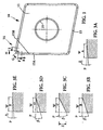
- the cutting insert is rhombic, the corner portion shown in FIG. 1 having a nose angle of about 60 to 80°. However, it may also be square, rectangular, triangular or hexagonal. When it is hexagonal, it may also be in the form of a so-called trigonal insert.
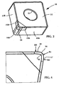
- the insert in this embodiment is made of cemented carbide having a cubic boron nitride (CBN) corner portion, but may also be made completely of any of those materials or of any other suitable material.
- CBN cubic boron nitride
- the cutting insert 10 comprises an upper surface 11, a lower surface 12 substantially parallel with said upper surface, and at least three side surface 13A,13B extending between said upper and lower surfaces.
- the upper surface 11 is planar in this embodiment and extends perpendicularly relative to said at least three side surfaces.
- a transition between two adjacent side surfaces 13A,13B forms a rounded nose radius surface 14A at a cutting insert corner 14.
- the cutting insert 10 comprises a peripheral land 15, constituted by at - least two peripheral lands 15A and 15B, bridging the upper and side surfaces at least at the corner portion 14.
- the peripheral lands 15A and 15B in this embodiment encircles the entire cutting insert periphery.
- the peripheral lands 15A and 15B in this embodiment are of different configuration.
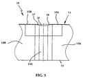
- the peripheral lands 15A and 15B slope at chamfer angles ⁇ A - ⁇ E (as illustrated by Figs. 3A-3E ) relative to a plane P containing the upper surface 11.
- the peripheral land is adapted to strengthen the cutting edges of the cutting insert.
- the upper surface 11 is planar and connects directly to the peripheral land 15 to allow a strong configuration.
- the nose cutting edge 16 is defined by at least one radius R1.
- Each operative cutting corner 14 comprises at least one convex wiper edge 17, 18 connected to the nose cutting edge 16.
- the nose radius surface 14A may be symmetrical with respect to the corner bisector B. This results in the advantage that the cutting insert becomes symmetrical, thereby enabling both left-hand and right-hand turning with the same insert, i.e., both left-hand and right-hand holders may be used for this cutting insert.
- the cutting insert 10 in this embodiment has a through-going hole 21 extending perpendicularly to the surfaces 11 and 12.
- the chamfer angle ⁇ c in a cross-section at the nose cutting edge 16 is larger than the chamfer angle ⁇ E in a cross-section a distance away from the nose cutting edge 16.
- the chamfer angle ⁇ C in the cross-section at the nose cutting edge 16 is larger than the chamfer angle in a cross-section at said first 17 or second 18 wiper edge.
- the peripheral land 15A and 15B follows a substantially straight line in a cross-section through the cutting insert 10, such as shown in Figs. 3A-3E .
- the peripheral land 15 has a continuously varying chamfer angle ⁇ at the corner portion 14.
- the chamfer angle ⁇ C in a cross-section as illustrated by Fig.
- the peripheral land 15 in a plan view has a substantially constant width W A W E , as illustrated by Figs. 3A-3E .
- the land width W E is however slightly larger than the widths W A -W D .
- the land widths may vary similar to the variations of the chamfer angle.
- the first wiper edge 17 is defined by at least one first wiper radius R2 and the second wiper edge 18 is defined by at least one second wiper radius R3, said radii R1-R3 have different points of origin.
- the radii R2 and R3 can be equally large.
- the peripheral land 15 at each first and second wiper edge 17, 18 has a continuously varying chamfer angle ⁇ .
- the angle ⁇ A is chosen within the range 5 to 20°
- the angle ⁇ B is chosen within the range 10 to 30°
- the angle ⁇ C is chosen within the range 15 to 60°
- the angle ⁇ D is chosen within the range 10 to 30°
- the angle ⁇ E is chosen within the range 5 to 20°.
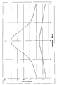
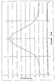
- the projected height Z of the chamfer when viewed perpendicular to the side surface 13A, 13B or nose radius surface 14A may vary in the range disclosed in Fig. 6B or as follows (in mm): A B C D E 0.004 0.009 0.01 0.009 0.004 0.18 0.29 0.86 0.29 0.18
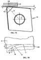
- Figs. 7A and 7B show the cutting insert during turning of a work piece 19 and an enlarged portion of the cutting insert and the workpiece during a hard turning process, respectively.
- the depth of cut Y is equal to or less than the nose cutting edge radius R1, such that the uncut material for example does not reach the bisector B.
- the insert is positioned with a clearance angle ⁇ beyond the wiper edge 17.
- the size of the chip 20 to be removed is determined by the depth of cut Y and the feed per revolution X. The thickness of the chip transfers into zero at the convex wiper edge 17.
- peripheral land 15 Since the peripheral land 15 has a chamfer that is most blunt at the bisector of the corner portion 14 that portion withstands wear while the wiper edge 17 that cuts the thin part of the chip is relatively sharp a good surface fineness is obtained.
- the fact that that the peripheral land 15, 15A,1 5B in a plan view has a substantially constant width W A -W E provides for a smaller variation in cutting edge position when used in a tool holder.
- the active corner of the cutting insert is a section of CBN and thus the cutting edges 16, 17 and 18 are comprised of CBN.
- any other suitable cutting material can be used all due the machining application.
- a cutting insert according to the present invention has a more blunt chamfer angle about the bisector of its cutting corner to protect the corner from breakage during high feeds while the wiper edge has a less blunt to diminish the radial forces.
- a cutting insert for turning is proposed that improves the fineness of the machined surface and significantly improves tool life.
Landscapes
- Engineering & Computer Science (AREA)
- Mechanical Engineering (AREA)
- Cutting Tools, Boring Holders, And Turrets (AREA)
- Milling Processes (AREA)
Claims (9)
- Schneideinsatz für das Drehen mit einer oberen Fläche (11), einer unteren Fläche (12), die im wesentlichen parallel zu der oberen Fläche ist, und wenigstens drei Seitenflächen (13A, 13B), die sich zwischen den oberen und unteren Flächen erstrecken, wobei ein Übergang zwischen zwei zueinander benachbarten Seitenflächen (13A, 13B) eine abgerundete Nasenradiusfläche (14A) an einer Ecke (14) des Schneideinsatzes bildet, der Schneideinsatz eine periphere Fase (15, 15A, 15B) aufweist, welche die obere Fläche und die Seitenflächen zumindest an dem Eckenabschnitt (14) unter einem Fasenwinkel (βA-βE) überbrückt, und eine Schnittlinie zwischen der Fase (15, 15A, 15B) und der Nasenradiusfläche (14A) aufweist, die eine Nasenschneidkante (16) bildet, wobei die Nasenschneidkante (16) durch wenigstens einen Radius (R1) definiert ist und die Schneidecke wenigstens eine gekrümmte Planschneide (17, 18) aufweist, wobei der Fasenwinkel (βC) in einem Querschnitt an der Nasenschneidkante (16) größer ist als der Fasenwinkel in einem Querschnitt in einem Abstand von der Nasenschneidkante (16), dadurch gekennzeichnet, daß die periphere Fase (15, 15A, 15B) in einer Draufsicht eine im wesentlichen konstante Breite (WA-WE) hat.
- Schneideinsatz nach Anspruch 1, dadurch gekennzeichnet, daß der Fasenwinkel (βC) im Querschnitt an der Nasenschneidkante (16) größer ist als der Fasenwinkel im Querschnitt an der Planschneide.
- Schneideinsatz nach Anspruch 1 oder 2, dadurch gekennzeichnet, daß die periphere Fase als eine Abschrägung (15) vorgesehen ist, die die gesamte Peripherie des Schneideinsatzes umgibt.
- Schneideinsatz nach einem der vorangegangenen Ansprüche, dadurch gekennzeichnet, daß die periphere Fase (15, 15A, 15B) einer im wesentlichen geraden Linie im Querschnitt durch den Schneideinsatz folgt.
- Schneideinsatz nach einem der vorangegangenen Ansprüche, dadurch gekennzeichnet, daß die periphere Fase (15, 15A, 15B) an dem Eckenabschnitt (14) einen kontinuierlich variierenden Fasenwinkel (β) hat.
- Schneideinsatz nach Anspruch 5, dadurch gekennzeichnet, daß der Fasenwinkel (βC) in einem Querschnitt an der Nasenschneidkante (16) größer ist als der Fasenwinkel (βE) in einem Querschnitt an einer ersten Planschneide (17, 18).
- Schneideinsatz nach einem der vorangegangenen Ansprüche, dadurch gekennzeichnet, daß die Schneidecke (14) eine erste Planschneide aufweist, die durch wenigstens einen Radius (R2) definiert ist, und eine zweite Planschneide aufweist, die durch wenigstens einen Radius (R3) definiert ist, wobei die Radien (R1-R3) verschiedene Ursprungspunkte haben.
- Schneideinsatz nach Anspruch 7, dadurch gekennzeichnet, daß die erste und die zweite Planschneide (17, 18) jeweils einen kontinuierlich variierenden Fasenwinkel (β) haben.
- Schneideinsatz nach einem der vorangegangenen Ansprüche, dadurch gekennzeichnet, daß der Schneideinsatz (10) teilweise oder vollständig aus kubischem Bornitrid besteht.
Applications Claiming Priority (2)
| Application Number | Priority Date | Filing Date | Title |
|---|---|---|---|
| SE0500414A SE530153C2 (sv) | 2005-02-22 | 2005-02-22 | Skär för svarvning med ett perifert land av konstant bredd |
| PCT/SE2006/000192 WO2006091141A1 (en) | 2005-02-22 | 2006-02-13 | A cutting insert with a varying chamfer angle at the nose cutting edge |
Publications (2)
| Publication Number | Publication Date |
|---|---|
| EP1850992A1 EP1850992A1 (de) | 2007-11-07 |
| EP1850992B1 true EP1850992B1 (de) | 2009-10-14 |
Family
ID=36927685
Family Applications (1)
| Application Number | Title | Priority Date | Filing Date |
|---|---|---|---|
| EP06716884A Expired - Lifetime EP1850992B1 (de) | 2005-02-22 | 2006-02-13 | Schneideeinsatz mit veränderlichem anschnittwinkel an der spitzenschnittkante |
Country Status (7)
| Country | Link |
|---|---|
| US (1) | US7438508B2 (de) |
| EP (1) | EP1850992B1 (de) |
| KR (1) | KR101257373B1 (de) |
| CN (1) | CN101107089B (de) |
| DE (1) | DE602006009765D1 (de) |
| SE (1) | SE530153C2 (de) |
| WO (1) | WO2006091141A1 (de) |
Cited By (1)
| Publication number | Priority date | Publication date | Assignee | Title |
|---|---|---|---|---|
| EP3311941A1 (de) * | 2016-10-19 | 2018-04-25 | Seco Tools Ab | Dreheinsatz |
Families Citing this family (52)
| Publication number | Priority date | Publication date | Assignee | Title |
|---|---|---|---|---|
| US7726420B2 (en) * | 2004-04-30 | 2010-06-01 | Smith International, Inc. | Cutter having shaped working surface with varying edge chamfer |
| US7476062B2 (en) * | 2006-05-08 | 2009-01-13 | Kennametal Inc. | Cutting insert with recessed corners |
| SE530289C2 (sv) * | 2006-10-13 | 2008-04-22 | Seco Tools Ab | Negativt svarvskär med en fas mellan skäregg och släppningssida |
| US20080276771A1 (en) * | 2007-05-07 | 2008-11-13 | Air Products And Chemicals, Inc. | Method For Hardening A Machined Article |
| USD597109S1 (en) * | 2007-08-21 | 2009-07-28 | Iscar, Ltd. | Cutting insert |
| DE102009056039A1 (de) * | 2009-11-27 | 2011-06-01 | Schaeffler Technologies Gmbh & Co. Kg | Schneidwerkzeug |
| AT12004U1 (de) * | 2010-02-25 | 2011-09-15 | Ceratizit Austria Gmbh | Schneideinsatz |
| JP5895456B2 (ja) * | 2010-11-15 | 2016-03-30 | 三菱マテリアル株式会社 | 切削インサート |
| EP2455172B1 (de) * | 2010-11-19 | 2013-01-16 | SECO TOOLS AB (publ) | Schneideinsatz mit sich veränderndem Keil- oder Freiwinkel und Werkzeughalter mit einem solchen Schneideinsatz |
| EP2484467B1 (de) * | 2011-02-03 | 2014-05-07 | Seco Tools AB | Schneideinsatz mit symmetrischen, gerundeten Schneidkanten |
| JP5594213B2 (ja) * | 2011-03-30 | 2014-09-24 | 三菱マテリアル株式会社 | 切削インサート |
| KR20140038975A (ko) * | 2011-05-03 | 2014-03-31 | 다이아몬드 이노베이션즈, 인크. | 칩 박육화를 유발하는 와이퍼를 선단 날 상에 갖는 인서트 |
| KR20140039309A (ko) | 2011-07-22 | 2014-04-01 | 케나메탈 인디아 리미티드 | 인덱서블 드릴 인서트 |
| DE102012012980B4 (de) | 2011-07-22 | 2019-10-17 | Kennametal India Ltd. | Bohrwerkzeug |
| DE102012014092B4 (de) | 2011-07-22 | 2020-12-17 | Kennametal India Ltd. | Indexierbarer Bohreinsatz sowie Bohrkörper mit indexierbarem Bohreinsatz |
| CN103447591B (zh) | 2012-05-28 | 2020-02-28 | 钴碳化钨硬质合金印度有限公司 | 四角形的可转位的钻头镶片 |
| SE537377C2 (sv) * | 2012-07-05 | 2015-04-14 | Sandvik Intellectual Property | Skärinsats och fräsverktyg för fräsning av ett spår i ett arbetsstycke |
| WO2014116571A1 (en) | 2013-01-23 | 2014-07-31 | Kennametal India Limited | Indexable drill insert and rotary cutting tool employing same |
| US10562199B2 (en) * | 2014-01-15 | 2020-02-18 | The Gillette Company Llc | Connecting member |
| JP6352639B2 (ja) * | 2014-01-24 | 2018-07-04 | 京セラ株式会社 | 切削インサート、切削工具および切削加工物の製造方法 |
| JP6356781B2 (ja) * | 2014-02-26 | 2018-07-11 | 京セラ株式会社 | 切削インサート、切削工具及び切削加工物の製造方法 |
| EP3117938B1 (de) * | 2014-04-22 | 2021-08-04 | Tungaloy Corporation | Schneideeinsatz und schneidewerkzeug |
| US10245644B2 (en) * | 2014-09-16 | 2019-04-02 | Sumitomo Electric Industries, Ltd. | Cutting insert and method of manufacturing the same |
| CN104439317B (zh) * | 2014-09-18 | 2018-10-09 | 厦门金鹭特种合金有限公司 | 一种具有多种刃口组合的切削刀片 |
| CN104308206B (zh) * | 2014-10-21 | 2018-02-02 | 台州市锐安硬质合金工具有限公司 | 车削用可转位刀片 |
| DE102015224276A1 (de) * | 2014-12-05 | 2016-06-09 | Ceramtec Gmbh | Schneidplattengeometrie zur Schnittkraftreduzierung beim Stechdrehen und ziehenden Schnitt |
| WO2016189935A1 (ja) * | 2015-05-28 | 2016-12-01 | 京セラ株式会社 | 切削インサートおよび切削工具、並びに切削加工物の製造方法 |
| JP1558993S (de) * | 2015-11-17 | 2019-09-02 | ||
| WO2017090770A1 (ja) * | 2015-11-28 | 2017-06-01 | 京セラ株式会社 | 切削インサート、切削工具及び切削加工物の製造方法 |
| JP6612900B2 (ja) * | 2016-02-05 | 2019-11-27 | 京セラ株式会社 | インサート、切削工具及び切削加工物の製造方法 |
| WO2017217481A1 (ja) | 2016-06-17 | 2017-12-21 | 京セラ株式会社 | 切削インサート、切削工具及び切削加工物の製造方法 |
| EP3260225B1 (de) * | 2016-06-20 | 2022-11-30 | Sandvik Intellectual Property AB | Dreheinsatz |
| CN106312113A (zh) * | 2016-11-08 | 2017-01-11 | 哈尔滨理工大学 | 一种具有变倒棱宽度和角度的车削刀片 |
| CN106346030B (zh) * | 2016-11-08 | 2018-11-23 | 哈尔滨理工大学 | 一种双圆弧车刀片 |
| CN106424788A (zh) * | 2016-11-08 | 2017-02-22 | 哈尔滨理工大学 | 一种具有变倒棱宽度的车削刀片 |
| JP6766998B2 (ja) * | 2016-12-15 | 2020-10-14 | 住友電工焼結合金株式会社 | スローアウェイチップ |
| KR20180088638A (ko) * | 2016-12-26 | 2018-08-06 | 스미또모 덴꼬오 하드메탈 가부시끼가이샤 | 절삭 공구 및 그 제조 방법 |
| WO2019026698A1 (ja) * | 2017-08-02 | 2019-02-07 | 京セラ株式会社 | 切削インサート、切削工具及び切削加工物の製造方法 |
| WO2019065525A1 (ja) * | 2017-09-27 | 2019-04-04 | 京セラ株式会社 | 切削インサート、切削工具及び切削加工物の製造方法 |
| WO2019069916A1 (ja) * | 2017-10-02 | 2019-04-11 | 京セラ株式会社 | 切削インサート、切削工具及び切削加工物の製造方法 |
| EP3476508A1 (de) * | 2017-10-31 | 2019-05-01 | Sandvik Intellectual Property AB | Dreheinsatz |
| EP3542936A1 (de) | 2018-03-22 | 2019-09-25 | AB Sandvik Coromant | Schneideinsatz für ein schulterfräswerkzeug |
| JP7114732B2 (ja) * | 2018-10-29 | 2022-08-08 | 京セラ株式会社 | 切削インサート、切削工具及び切削加工物の製造方法 |
| US11344958B2 (en) * | 2019-04-18 | 2022-05-31 | Tungaloy Corporation | Cutting insert |
| AT16933U1 (de) * | 2019-07-11 | 2020-12-15 | Ceratizit Austria Gmbh | Doppelseitiger Schneideinsatz zum Fräsen |
| US12337391B2 (en) * | 2020-05-26 | 2025-06-24 | Kyocera Corporation | Cutting insert, cutting tool, and method for manufacturing machined product |
| DE102020117101A1 (de) * | 2020-06-29 | 2021-12-30 | Kennametal Inc. | Schneideinsatz und Zerspanungswerkzeug |
| CN114309682A (zh) | 2020-09-30 | 2022-04-12 | 肯纳金属公司 | 切削刀片 |
| JP7041408B1 (ja) * | 2021-04-30 | 2022-03-24 | 株式会社タンガロイ | 切削インサート |
| CN117916041A (zh) * | 2021-10-21 | 2024-04-19 | 住友电工硬质合金株式会社 | 切削刀片 |
| US12485492B2 (en) * | 2023-05-31 | 2025-12-02 | Sumitomo Electric Hardmetal Corp. | Cutting insert and processing method |
| US20250162041A1 (en) * | 2023-11-22 | 2025-05-22 | Kennametal Inc. | Variable functional edge preparation |
Family Cites Families (15)
| Publication number | Priority date | Publication date | Assignee | Title |
|---|---|---|---|---|
| CH642883A5 (fr) * | 1981-05-19 | 1984-05-15 | Stellram Sa | Plaquette de coupe pour usinage par enlevement de copeaux. |
| US4526853A (en) * | 1982-10-15 | 1985-07-02 | Konishiroku Photo Industry Co., Ltd. | Method of providing an increased brightening effect and silver halide photographic material having increased brightening effect |
| SE459237B (sv) * | 1987-10-26 | 1989-06-19 | Sandvik Ab | Vaendskaer foer planfraesning |
| DE3823199A1 (de) * | 1988-07-08 | 1990-01-11 | Feldmuehle Ag | Schneidplatte fuer spanabhebende bearbeitung |
| US5222843A (en) * | 1992-06-22 | 1993-06-29 | Valenite Inc. | Insert for light feed, light depth of cut |
| SE501913C2 (sv) * | 1993-10-21 | 1995-06-19 | Sandvik Ab | Skär för skärande verktyg |
| SE509224C2 (sv) * | 1994-05-19 | 1998-12-21 | Sandvik Ab | Vändskär |
| EP0830228B1 (de) * | 1995-06-06 | 2000-07-26 | Widia GmbH | Verfahren zur spanenden bearbeitung von zylindrischen konturen, vorrichtung zur durchführung des verfahrens und schneideinsatz hierzu |
| IL118797A (en) * | 1996-07-05 | 1999-10-28 | Iscar Ltd | Cutting insert |
| JPH1043912A (ja) | 1996-07-31 | 1998-02-17 | Ngk Spark Plug Co Ltd | スローアウェイチップ |
| JP4465809B2 (ja) * | 1999-07-09 | 2010-05-26 | 三菱マテリアル株式会社 | スローアウェイチップ |
| JP2002192407A (ja) * | 2000-12-26 | 2002-07-10 | Ngk Spark Plug Co Ltd | 切削工具 |
| US6623217B2 (en) * | 2001-09-24 | 2003-09-23 | Valenite, Inc. | Indexable turning insert |
| JP4121449B2 (ja) * | 2003-01-16 | 2008-07-23 | 日本特殊陶業株式会社 | スローアウェイチップ及びバイト |
| DE10308234A1 (de) * | 2003-02-25 | 2004-09-09 | Kratz, Heinz Hubert, Dipl.-Ing. | Schneidengeometrie |
-
2005
- 2005-02-22 SE SE0500414A patent/SE530153C2/sv not_active IP Right Cessation
-
2006
- 2006-02-13 WO PCT/SE2006/000192 patent/WO2006091141A1/en not_active Ceased
- 2006-02-13 US US11/307,562 patent/US7438508B2/en active Active
- 2006-02-13 KR KR1020077018877A patent/KR101257373B1/ko not_active Expired - Fee Related
- 2006-02-13 EP EP06716884A patent/EP1850992B1/de not_active Expired - Lifetime
- 2006-02-13 DE DE602006009765T patent/DE602006009765D1/de not_active Expired - Lifetime
- 2006-02-13 CN CN200680003242XA patent/CN101107089B/zh not_active Expired - Lifetime
Cited By (3)
| Publication number | Priority date | Publication date | Assignee | Title |
|---|---|---|---|---|
| EP3311941A1 (de) * | 2016-10-19 | 2018-04-25 | Seco Tools Ab | Dreheinsatz |
| WO2018073172A1 (en) * | 2016-10-19 | 2018-04-26 | Seco Tools Ab | Turning insert |
| US11052465B2 (en) | 2016-10-19 | 2021-07-06 | Seco Tools Ab | Turning insert |
Also Published As
| Publication number | Publication date |
|---|---|
| DE602006009765D1 (de) | 2009-11-26 |
| SE0500414L (sv) | 2006-08-23 |
| SE530153C2 (sv) | 2008-03-11 |
| KR101257373B1 (ko) | 2013-04-23 |
| CN101107089A (zh) | 2008-01-16 |
| EP1850992A1 (de) | 2007-11-07 |
| WO2006091141A1 (en) | 2006-08-31 |
| US20060228179A1 (en) | 2006-10-12 |
| CN101107089B (zh) | 2012-07-04 |
| KR20070106520A (ko) | 2007-11-01 |
| US7438508B2 (en) | 2008-10-21 |
Similar Documents
| Publication | Publication Date | Title |
|---|---|---|
| EP1850992B1 (de) | Schneideeinsatz mit veränderlichem anschnittwinkel an der spitzenschnittkante | |
| EP1855828B1 (de) | Schneideeinsatz mit kleinem anschnittwinkel an der spitzenschnittkante | |
| KR100650099B1 (ko) | 접선 절삭 삽입체 및 삽입체 홀더 | |
| EP1539413B9 (de) | Schneideinsatz und verfahren | |
| KR100892552B1 (ko) | 접선 커팅 인서트 및 밀링 커터 | |
| US7455483B2 (en) | Milling insert and a milling tool | |
| US5460464A (en) | Cutting insert | |
| US20020098048A1 (en) | Cutting insert | |
| KR20020065390A (ko) | 스로-어웨이 팁 | |
| KR102327958B1 (ko) | 선삭 인서트 | |
| US7476062B2 (en) | Cutting insert with recessed corners | |
| US6604893B2 (en) | Cutting insert with wiper | |
| CN114951719A (zh) | 切削刀片 | |
| JP2004195563A (ja) | 刃先交換式回転工具用インサート及び刃先交換式回転工具 | |
| CN101107088B (zh) | 在前端切削刃处具有小倒角角度的切削刀片 | |
| JP2019130647A (ja) | 切削インサート、切削工具及び切削加工物の製造方法 | |
| JP2009184086A (ja) | スローアウェイチップ | |
| AU2002312494A1 (en) | Cutting insert with wiper |
Legal Events
| Date | Code | Title | Description |
|---|---|---|---|
| PUAI | Public reference made under article 153(3) epc to a published international application that has entered the european phase |
Free format text: ORIGINAL CODE: 0009012 |
|
| 17P | Request for examination filed |
Effective date: 20070525 |
|
| AK | Designated contracting states |
Kind code of ref document: A1 Designated state(s): CZ DE FR GB IT SE |
|
| DAX | Request for extension of the european patent (deleted) | ||
| RBV | Designated contracting states (corrected) |
Designated state(s): CZ DE FR GB IT SE |
|
| GRAP | Despatch of communication of intention to grant a patent |
Free format text: ORIGINAL CODE: EPIDOSNIGR1 |
|
| GRAS | Grant fee paid |
Free format text: ORIGINAL CODE: EPIDOSNIGR3 |
|
| GRAA | (expected) grant |
Free format text: ORIGINAL CODE: 0009210 |
|
| AK | Designated contracting states |
Kind code of ref document: B1 Designated state(s): CZ DE FR GB IT SE |
|
| REG | Reference to a national code |
Ref country code: GB Ref legal event code: FG4D |
|
| REF | Corresponds to: |
Ref document number: 602006009765 Country of ref document: DE Date of ref document: 20091126 Kind code of ref document: P |
|
| PG25 | Lapsed in a contracting state [announced via postgrant information from national office to epo] |
Ref country code: SE Free format text: LAPSE BECAUSE OF FAILURE TO SUBMIT A TRANSLATION OF THE DESCRIPTION OR TO PAY THE FEE WITHIN THE PRESCRIBED TIME-LIMIT Effective date: 20091014 |
|
| PLBE | No opposition filed within time limit |
Free format text: ORIGINAL CODE: 0009261 |
|
| STAA | Information on the status of an ep patent application or granted ep patent |
Free format text: STATUS: NO OPPOSITION FILED WITHIN TIME LIMIT |
|
| 26N | No opposition filed |
Effective date: 20100715 |
|
| REG | Reference to a national code |
Ref country code: FR Ref legal event code: PLFP Year of fee payment: 11 |
|
| REG | Reference to a national code |
Ref country code: FR Ref legal event code: PLFP Year of fee payment: 12 |
|
| PGFP | Annual fee paid to national office [announced via postgrant information from national office to epo] |
Ref country code: CZ Payment date: 20170126 Year of fee payment: 12 |
|
| REG | Reference to a national code |
Ref country code: FR Ref legal event code: PLFP Year of fee payment: 13 |
|
| PG25 | Lapsed in a contracting state [announced via postgrant information from national office to epo] |
Ref country code: CZ Free format text: LAPSE BECAUSE OF NON-PAYMENT OF DUE FEES Effective date: 20180213 |
|
| PGFP | Annual fee paid to national office [announced via postgrant information from national office to epo] |
Ref country code: IT Payment date: 20210112 Year of fee payment: 16 |
|
| PGFP | Annual fee paid to national office [announced via postgrant information from national office to epo] |
Ref country code: FR Payment date: 20230123 Year of fee payment: 18 |
|
| PG25 | Lapsed in a contracting state [announced via postgrant information from national office to epo] |
Ref country code: IT Free format text: LAPSE BECAUSE OF NON-PAYMENT OF DUE FEES Effective date: 20220213 |
|
| PGFP | Annual fee paid to national office [announced via postgrant information from national office to epo] |
Ref country code: GB Payment date: 20230105 Year of fee payment: 18 |
|
| P01 | Opt-out of the competence of the unified patent court (upc) registered |
Effective date: 20230603 |
|
| GBPC | Gb: european patent ceased through non-payment of renewal fee |
Effective date: 20240213 |
|
| PG25 | Lapsed in a contracting state [announced via postgrant information from national office to epo] |
Ref country code: GB Free format text: LAPSE BECAUSE OF NON-PAYMENT OF DUE FEES Effective date: 20240213 |
|
| PG25 | Lapsed in a contracting state [announced via postgrant information from national office to epo] |
Ref country code: FR Free format text: LAPSE BECAUSE OF NON-PAYMENT OF DUE FEES Effective date: 20240229 |
|
| PG25 | Lapsed in a contracting state [announced via postgrant information from national office to epo] |
Ref country code: GB Free format text: LAPSE BECAUSE OF NON-PAYMENT OF DUE FEES Effective date: 20240213 Ref country code: FR Free format text: LAPSE BECAUSE OF NON-PAYMENT OF DUE FEES Effective date: 20240229 |
|
| PGFP | Annual fee paid to national office [announced via postgrant information from national office to epo] |
Ref country code: DE Payment date: 20241231 Year of fee payment: 20 |
|
| REG | Reference to a national code |
Ref country code: DE Ref legal event code: R071 Ref document number: 602006009765 Country of ref document: DE |