EP1850458A2 - Laufer für dynamo-elektrische Maschine - Google Patents
Laufer für dynamo-elektrische Maschine Download PDFInfo
- Publication number
- EP1850458A2 EP1850458A2 EP07008676A EP07008676A EP1850458A2 EP 1850458 A2 EP1850458 A2 EP 1850458A2 EP 07008676 A EP07008676 A EP 07008676A EP 07008676 A EP07008676 A EP 07008676A EP 1850458 A2 EP1850458 A2 EP 1850458A2
- Authority
- EP
- European Patent Office
- Prior art keywords
- rotor
- spacer
- coils
- dynamo
- coil
- Prior art date
- Legal status (The legal status is an assumption and is not a legal conclusion. Google has not performed a legal analysis and makes no representation as to the accuracy of the status listed.)
- Granted
Links
Images


Classifications
-
- H—ELECTRICITY
- H02—GENERATION; CONVERSION OR DISTRIBUTION OF ELECTRIC POWER
- H02K—DYNAMO-ELECTRIC MACHINES
- H02K1/00—Details of the magnetic circuit
- H02K1/06—Details of the magnetic circuit characterised by the shape, form or construction
- H02K1/22—Rotating parts of the magnetic circuit
- H02K1/32—Rotating parts of the magnetic circuit with channels or ducts for flow of cooling medium
Definitions
- the present invention relates to a dynamo-electric machine rotor and, more particularly, to a rotor coil cooling structure configured to feed coolant gas between adjacent coil ends.
- a dynamo-electric machine such as a turbine generator is composed of a hollow cylindrical stator and a cylindrical rotor with a diameter somewhat smaller than that of the hollow portion which are concentrically arranged with an air gap between them.
- conductive bars i.e., so-called coils of copper or the like are arranged in the axial direction of core slots, When the rotor is rotated while its coils are energized, current is induced on the stator side.
- stator and rotor are forcedly cooled by feeding coolant gas into the machine by means of, e.g., placement of a fan in the rotor.
- coolant gas e.g., a fan
- the cooling performance of rotor coils which use rotational centrifugal force as the driving force for coolant gas is an important factor which influences the performance and build of a generator.
- FIG. 29 shows a sectional view of ends of conventional rotor coils.
- FIG. 30 shows a horizontally spread-out view of the ends of the rotor coils.
- a conventional dynamo-electric machine rotor has a ventilating groove 10A in the longitudinal direction of each of rotor coils 10 and cools the rotor coils 10 by feeding coolant gas A through the grooves.
- the rotor coils 10 of stacked turns are fitted into slots which are circumferentially formed at predetermined intervals in a core 30 integrated with a rotor shaft 13 to form multiple nested rings. Ends 10E of the rotor coils 10 which are located outside an end of the rotor core are held by an retaining ring 34 and an retaining ring support 35 against rotational centrifugal force. As shown in FIG. 29, the ends 10E of the rotor coils 10, whose outer side is surrounded by the retaining ring 34, are held at predetermined intervals while a spacer 20 shown in FIG. 31 is arranged between each two adjacent coils. An insulating cylinder 40 is inserted to maintain electrical insulation between the outermost portion of the rotor coil ends 10E and the retaining ring 34.
- insulators are inserted between adjacent stacked turns of each rotor coil and between the core slots and the rotor coils, and the upper temperature limit is defined on the basis of the heat-proof temperatures of the insulators and the like.
- coolant gas passes through an air gap between the rotor shaft 13 and the retaining ring support 35 and is guided to the retaining ring 34, and part thereof is guided to a ventilating channel in each rotor coil 10 from a ventilating inlet formed in a side of the rotor coil 10.
- the coolant gas guided into the ventilating channel of the rotor coil 10 flows through the ventilating channel in the longitudinal direction of the rotor coil 10, thereby cooling the rotor coil 10.
- the coolant gas passes through a radial duct 14 in the core and is discharged to the outer periphery of the rotor.
- each partition plate has an opening near the border between a coil linear portion 12 and a coil circular portion 11, and cooling is performed by causing coolant gas to pass in the directions indicated by arrows.
- each rotor coil has the ventilating groove 10A
- coolant gas flows in the longitudinal direction. Accordingly, the temperature of the coolant gas becomes higher toward the downstream side, and the temperature of one of the coils which is circumferentially distant from a magnetic pole center and is near the core end is higher than that of one near the magnetic pole center where an inlet 10B for coolant gas is located, as shown in FIG. 30.
- the temperature of an outer coil is higher than that of an inner coil, and it is highly possible that the distribution of temperature becomes wider in the axial direction and circumferential direction of the rotor coils.
- FIG. 33 shows an example of a set of temperature distributions.
- the temperatures of rotor coils are strictly limited by the upper temperature limit for a member used as an insulator for the coils, If the temperature is locally high at a part of a coil, there arises the need to limit field current and suppress the amount of heat generated even when the temperatures at other parts are sufficiently lower than the upper temperature limit. Accordingly, it is impossible to turn up a dynamo-electric machine. Also, if temperatures differ among coils of a large number of turns, shaft vibration occurs due to imbalance in thermal expansion among the rotor coils, and the reliability of the generator decreases.
- a rotor coil of a turbine generator is formed by stacking a plurality of turns each generally having a thickness of about several mm. Since the thin turns are not tightly bound nor held by one another, they each thermally stretch with an increase in temperature during the operation of the generator. For this reason, it is desirable for a spacer to be in contact with all turns at longitudinally identical positions, if possible.
- a zigzag ventilating groove is formed in each side of a spacer. Accordingly, surfaces on a side of each spacer which are in contact with a coil are staggered and are discontinuous in the longitudinal direction. For this reason, the coil end holding power in the technique described in National Publication of International Patent Application No. 2000-508508 is lower than a rotor which uses a plain spacer without a ventilating groove in each side.
- the present invention has been made in consideration of the above-described conventional drawbacks, and has as its object to provide a dynamo-electric machine rotor which can sufficiently cool a rotor coil with simple configuration without providing a component such as a partition plate and whose coil holding power is not impaired at an end of the rotor coil.
- a dynamo-electric machine rotor in which spaced core slots are formed in a cylindrical rotor core, rotor coils of stacked turns are fitted into the core slots to form multiple nested rings around a magnetic pole of the rotor and, ends of the rotor coils are fixed by an retaining ring, and a spacer is arranged in each of circumferential gaps between the ends of the rotor coils, wherein each spacer has a length not more than lengths of linear portions at the ends of corresponding ones of the rotor coils, a cut-out is formed across at least one of two sides of the spacer which are in contact with the linear portions at the ends of the corresponding rotor coils except for a portion located inward in a radial direction of the rotor and an arbitrary portion to form a coolant gas ventilating channel having an axial extremity which communicates with a through hole formed in a tooth of the rotor core, and the
- a cut-out is formed across a side of a spacer inserted between conductors of ends of rotor coils except for a portion located inward in a radial direction of a rotor and an arbitrary portion to facilitate ventilation of coolant gas.
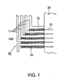
- FIG. 1 is a spread-out view of rotor coils 10 when an retaining ring and an insulating cylinder at an end of a rotor of a generator are removed, as seen from above.
- ends 10E of the rotor coils 10 space is provided between coil conductors of each adjacent two of coil circular portions 11 which are located outside a rotor core 30, and an integral-type spacer 20 whose details are shown in FIGS. 2(A) to 2(D) is provided between each adjacent two of coil linear portions 12.
- each spacer 20 has two sides which serve as coil contacting portions. A plurality of cut-outs are longitudinally formed in each coil connecting portion, and a communicating hole is formed in each of remaining parts.
- the spacer 20 is configured to feed coolant gas through a ventilating channel which is composed of the cut-outs and communicating holes and feed the gas after cooling to through holes 31 formed in a tooth of the core. Note that two of the through holes 31 are vertically formed in a tooth 33 of the rotor core 30, as shown in FIG. 6.
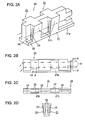
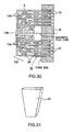
- FIGS. 2(A) to 2(D) are views showing an example of a spacer.
- FIG. 2(A) is a perspective view
- FIG. 2(B) is a side view
- FIG. 2(C) is a top view
- FIG. 2(D) is an end view of FIG. 2(B) taken along line IV-IV, as seen from an outlet for coolant gas.
- the spacer 20 in this example has a plurality of cut-outs 22 longitudinally formed at predetermined intervals in each of surfaces which are in contact with one sides of the linear portions 12 of the corresponding rotor coils 10 shown in FIG. 1, i.e., each of two contacting portions 21.
- a communicating hole 23 is formed in a remaining portion sandwiched between each adjacent two of the cut-outs 22.
- the spacer 20 is configured to feed coolant gas through the cut-outs 22 and communicating holes 23, as indicated by arrows.
- the linear portions 12 at ends of the rotor coils 10 directly exchange heat with coolant gas in the cut-outs 22 and are cooled.
- parts 21h which are each sandwiched between the corresponding cut-outs 22 and a portion 21a located inward in the radial direction of the rotor which is at a lower portion of a side of the spacer 20 serve as remaining portions and constitute the contacting portion 21, as in FIG. 2(A), and hold a side of the linear portion 12 at the end 10E of the corresponding rotor coil 10.
- FIG. 3 shows a spacer 20A which has the cut-outs 22 only in one side, the left side in FIG. 3.
- FIGS. 4(A) to 4(C) show a spacer 20B whose contacting portions 21 on the right and left sides are asymmetrical. Note that FIGS. 4(A), 4(B), and 4(C) are a front view, a rear view, and a right side view, respectively, of the spacer 20B.
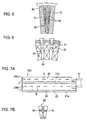
- FIG. 5 shows a radial sectional view of the spacer 20 in FIGS. 2(A) to 2(D) placed between the linear portions 12 at ends of the corresponding rotor coils 10, taken at the cut-outs 22.
- a ventilating channel 26 which is independent of lower space formed between the linear portions 12 at ends of the corresponding rotor coils 10 and a rotor shaft is formed at a side of the corresponding rotor coil 10 by the spacer 20.
- FIG. 6 is a cross-sectional view of the rotor core 30, with which an end face of each spacer 20 is in contact.
- the through holes 31 for discharging coolant gas which communicate with the ventilating channels 26 of the spacer 20 and communicate with an air gap between the rotor and a stator, are formed in each tooth 33 between slots 32 containing the rotor coils 10.
- each spacer need not be limited to one having one ventilating channel 26 on each side, as in the spacers 20, 20A, and 20B described above.
- Each spacer 20 may be formed such that the radially inward contacting portion 21a and a portion 21b near the center in the heightwise direction of the spacer 20 serve as a contacting portion which is in contact with a side of the corresponding rotor coil 10, thereby forming two horizontally split ventilating channels 26U and 26D at the side of the linear portion 12 of the rotor coil 10, as in, e.g., FIGS. 7(A) and 7(B) and 8.
- FIGS. 7(A) and 7(B) show a spacer 20C in which the cut-out 22 is split into upper and lower portions by the linear contacting portion 21b provided near the center in the heightwise direction.
- FIG. 8 shows a spacer 20D In which the contacting portion 21b is wavy.
- the flow directions of coolant gas are indicated by two rows A and B of arrows passing through the two ventilating channels 26U and 26D, which extend in the longitudinal direction of each of the spacers 20C and 20D.
- FIG. 9 shows an example, of a spacer 20E in which the contacting portion 21b is doglegged downward, i.e., toward the rotor shaft at a fourth to third of the length of the spacer 20E from an inlet for coolant gas.
- the contacting portion 21b which horizontally splits the ventilating channel 26 into the ventilating channels 26U and 26D, is linear.
- the contacting portion 21b is wavy.
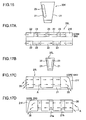
- FIGS. 11 and 12 each show an example in which the radially inward contacting portion 21a and the contacting portion 21b, which diagonally extends downward, are further extended inward beyond the radially inward contacting portion 21a of an extremity on the coil circular portion 11 side, as in contacting portions 21c and 21d, to project to be further inside than the inner periphery of the coils 10.
- the contacting portion 21b which horizontally splits the ventilating channel 26 into the ventilating channels 26U and 26D, may be linear, as in a spacer 20G in FIG. 11 or may be wavy, as in a spacer 20H in FIG. 12.
- FIG. 13 shows a configuration in which the ventilating channel 26 at a side of the linear portion 12 of the corresponding rotor coil 10 is configured to meander, as indicated by the arrows A, by forming a rotor radially outward side contacting portions 21e and the radially inward contacting portion 21a of a spacer 20I to alternately project toward the ventilating channel 26.
- This configuration makes it possible to ensure the ventilating channel 26, which is separate from a channel formed between the linear portions 12 at ends of the coils 10 and the rotor shaft, at a side of the linear portion 12 of the coil 10. Since each spacer is of integral type, the cross-sectional area between the coils 10 decreases, and the flow rate of coolant gas flowing between the coils 10 can be increased. Also, formation of the through holes 31 in the teeth 33 between the slots of the rotor core 30 makes it possible to ensure outlets for coolant gas flowing between the linear portions 12 of the rotor coils 10.
- each spacer 20 formed to alternately project toward the ventilating channel 26 makes it possible to enhance the holding power of the spacer 20.
- the ventilating channel 26, which is separate from a channel below the coils 10, is provided at a side of each coil 10 using any of the spacers 20 to 20I. Since coolant gas guided to the radially outward side by rotational centrifugal force is taken in and does not return to the channel below the coils 10, coolant gas can be effectively used to cool the sides of the coils 10. This makes it possible to achieve temperature distributions as shown in FIG. 28 better than those of a conventional rotor shown in FIG. 33. Also, it is possible to perform uniform cooling by changing the positions of the contacting portions 21 of each spacer 20.
- Provision of the through holes 31 for discharging coolant gas flowing between the coils 10 toward the air gap in the teeth 33 of the rotor core 30 makes it possible to discharge coolant gas whose temperature is increased after cooling between the coils 10 toward the air gap without letting the coolant gas flow into the rotor.
- the configuration is advantageous to a large rotating machine which requires minimization of the temperature of gas flowing into the rotor.
- Horizontal splitting of the ventilating channel 26 at a side of the coil 10 into two makes it possible to reduce imbalance, i.e., restrain much of coolant gas from flowing to the radially outward side due to centrifugal force and perform uniform cooling.
- Placement of an inlet for coolant gas in the bottom surface of each spacer 20 makes it possible to make more use of the effects of rotational centrifugal force and increases the opening area. Accordingly, a pressure drop at the inlet can be reduced.
- Extension of the contacting portions 21a and 21b, which are to come into contact with the coil 10, to below the coil, as in the contacting portions 21c and 21d, is expected to increase the uptake of gas.
- the radially outward side contacting portions 21e and the radially inward contacting portion 21a of each spacer 20 formed to alternately project toward the ventilating channel 26 make it possible to increase the area of contact with the coil 10.
- a large-capacity machine whose coils 10 have high heat stretchability can ensure cooling power and holding power.
- FIG. 14 shows a spread-out view of rotor coils 10 at an end of a rotor of a generator, as seen from above.
- An integral-type spacer 20J shown in FIGS. 15(A) to 15(C) is provided between coil linear portions 12 at ends of each adjacent two of the rotor coils 10, which are located outside a rotor core 30.
- the spacer 20J has a contacting portion 21f which bends coolant gas A to the radially inward of the rotor near an outlet and discharges the coolant gas A.
- each spacer may have a cut-out only in one side, as in a spacer 20K shown in FIG. 16, or may have cut-outs such that contacting portions 21 on the right and left sides which are in contact with the corresponding coils 10 are asymmetrical, as in a spacer 20L shown in FIGS.
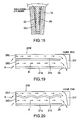
- FIG. 17(A) is a plan view
- FIG. 17(B) is a cross-sectional view
- FIG. 17(C) is a front view
- FIG. 17(D) is a rear view.
- FIG. 18 shows a radial sectional view of the spacer 20J In FIGS. 15(A) to 15(C) placed between the linear portions 12 at ends of the corresponding rotor coils 10.
- a ventilating channel 26 which is independent of lower space formed between the corresponding coils 10 and the rotor shaft is formed at a side of the corresponding coil 10 by the spacer 20J.
- An outlet 25 is formed in the ventilating channel 26 immediately in front of an end of the rotor core 30 by removing a part of a coil contacting portion 21a on the radially inward side of the spacer 20J.
- the spacer 20J is configured to discharge coolant gas to space located further inside than the Inner periphery of ends of the corresponding coils 10 which is formed between the coils 10 and the rotor shaft.
- each spacer 20 may be formed such that the radially Inward contacting portion 21a and a contacting portion 21b near the center in the heightwise direction of the spacer 20 are in contact with the coll 10 to split the ventilating channel 26 at a side of the corresponding coil 10.
- the ventilating channel 26 may be split such that the contacting portion 21b in contact with the corresponding coil 10 is linear, as in a spacer 20M in FIG. 19, or such that it is wavy, as in a spacer 20N in FIG. 20, and coolant gas may be discharged from the outlet 25.
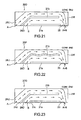
- a spacer 200 may be formed such that about a fourth to third of the spacer 200 from an extremity on the coil circular portion 11 side is not in contact with the linear portion 12 of the corresponding coil 10 at the bottom surface of the spacer 200 and such that a part of the contacting portion 21b horizontally splitting the ventilating channel 26 formed at a side of an end 10E of the coil 10 which is in the fourth to third may be diagonally extended downward to the radially inward side of the extremity on the coil circular portion 11 side of the spacer 200.
- the contacting portion 21b, which horizontally splits the ventilating channel 26, may be linear, as shown in FIG. 21, or may be wavy, as in a spacer 20P shown in FIG. 22.
- the contacting portions 21a and 21b which diagonally extend downward, may be further extended inward beyond the radially inward contacting portion 21a of an extremity on the coil circular portion 11 side, as in contacting portions 21c and 21d, to project to below the corresponding coil 10.
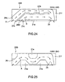
- the contacting portion 21b which splits the ventilating channel 26, may be linear, as in the spacer 20Q shown in FIG. 23, or may be wavy, as in a spacer 20R shown in FIG. 24.
- radially outward contacting portions 21e which are to come into contact with an insulating cylinder in FIG. 27 and the radially inward contacting portion 21a on the core 30 side may be provided to alternately project toward the ventilating channel 26, and a channel at a side of each coil 10 may be configured to meander.
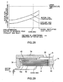
- FIG. 26 shows a sectional view of the end of the rotor, which uses the spacer 20Q.
- FIG. 27 is a graph showing the relationship between gas discharged from the spacers 20J to 20S and coolant gas (main stream).
- a stream of coolant gas flowing from the left side of FIG. 26 along the rotor shaft passes by an retaining ring support 35 provided at the left end (with respect to FIG. 26) of an retaining ring 34 and is split into a main stream C which travels straight ahead to the right (with respect to FIG. 26) along the rotor shaft, streams A and B which pass through ventilating channels 26U and 26D provided in the spacer 20Q, and a stream which heads upward (with respect to FIG. 26) away from the rotor shaft.
- a drop as shown in FIG. 27 occurs at the meeting of the two streams. More specifically, assuming that the main stream C is a stream along the rotor shaft and that the tributaries A and B are streams flowing through the spacer, a pressure drop with respect to a flow ratio is plotted with the abscissa representing the flow ratio between the tributaries and the main stream and the ordinate representing a pressure drop. As shown in FIG. 27, the drop is negative when the flow ratio is small and turns positive and increases as the flow ratio Increases. That is, the characteristic shown in FIG. 27 has a positive slope.
- the cooling effect of the coils is enhanced by using the drawing action of the main stream (the coolant gas stream C along the rotor shaft) on the tributaries (the coolant gas streams A and B passing through the spacer) in a region where the flow ratio is small.
- Each of the spacers 20J to 20S which are placed between the coil linear portions 12 at ends of the rotor coils 10, is in contact with the coil linear portions 12 at its two sides at radially inward side contact surfaces, has cut-outs formed across the sides except for the radially inward side contact surfaces, and is integrated with the coils 10 using a clip or the like.
- This configuration makes it possible to ensure the ventilating channel 26, which is separate from a channel formed between the coil linear portions 12 and the shaft, at one side or two sides of the coil linear portion 12.
- the cross-sectional area between the coils 10 decreases, and the flow rate of coolant gas flowing between the coil linear portions 12 can be increased. Additionally, it is possible to ensure outlets for coolant gas flowing between the coil linear portions 12 by forming each of the spacers 20J to 20L such that coolant gas is discharged to space below the coil linear portions 12 immediately in front of the end of the rotor core 30.
- the radially outward contacting portions 21e and radially inward contacting portion 21a formed to alternately project toward the ventilating channel 26, as in the spacer 20S, makes it possible to enhance the holding power of the spacer 20.
- a ventilating channel which is separate from a channel formed between the coil linear portions 12 and the shaft is provided at a side of the coil linear portion 12 at an end of each rotor coil 10 using any of the spacers 20J to 20S.
- each of the spacers 20J to 20S makes it possible to return coolant gas to a channel formed between an end of the coil 10 and the rotor shaft immediately in front of the rotor core 30 and feed the coolant gas through the subslot 33. Accordingly, the configuration is advantageous to a small rotating machine in, e.g., that it eliminates the need to form the through hole 31 in the tooth 33 of the core 30 and can reduce the cost.
- Horizontal splitting of the ventilating channel 26 at a side of the coil linear portion 12 into two makes it possible to reduce imbalance, i.e., restrain much of coolant gas from flowing to the radially outward side due to centrifugal force and perform uniform cooling.
- Placement of an inlet for coolant gas of each of the spacers 200 to 20S between an end of the coil 10 and the rotor shaft makes it possible to make more use of the effects of rotational centrifugal force and increases the opening area. Accordingly, a pressure drop at the inlet can be reduced.
- Extension of the contacting portions 21, which are to come into contact with the linear portion 12 at an end of the coil 10, to below the coil, as in the contacting portions 21c and 21d, is expected to increase the uptake of gas.
- the radially outward side contact surfaces and radially inward side contact surface of the spacer 20S formed to alternately project toward the ventilating channel 26 make it possible to Increase the area of contact with the linear portion 12 at an end of the coil 10.
- a large-capacity machine whose coils have high heat stretchability can ensure cooling power and holding power.
Landscapes
- Engineering & Computer Science (AREA)
- Power Engineering (AREA)
- Motor Or Generator Cooling System (AREA)
- Windings For Motors And Generators (AREA)
- Iron Core Of Rotating Electric Machines (AREA)
Applications Claiming Priority (1)
| Application Number | Priority Date | Filing Date | Title |
|---|---|---|---|
| JP2006125661A JP5016843B2 (ja) | 2006-04-28 | 2006-04-28 | 回転電機の回転子 |
Publications (3)
| Publication Number | Publication Date |
|---|---|
| EP1850458A2 true EP1850458A2 (de) | 2007-10-31 |
| EP1850458A3 EP1850458A3 (de) | 2011-04-13 |
| EP1850458B1 EP1850458B1 (de) | 2014-03-05 |
Family
ID=38028471
Family Applications (1)
| Application Number | Title | Priority Date | Filing Date |
|---|---|---|---|
| EP07008676.4A Active EP1850458B1 (de) | 2006-04-28 | 2007-04-27 | Laufer für dynamo-elektrische Maschine |
Country Status (4)
| Country | Link |
|---|---|
| US (1) | US7812501B2 (de) |
| EP (1) | EP1850458B1 (de) |
| JP (1) | JP5016843B2 (de) |
| CN (1) | CN101064450B (de) |
Cited By (10)
| Publication number | Priority date | Publication date | Assignee | Title |
|---|---|---|---|---|
| EP2112745A1 (de) * | 2008-04-21 | 2009-10-28 | Siemens Aktiengesellschaft | Verfahren zur Kühlung eines elektrischen Leiters |
| CN101789640A (zh) * | 2010-03-05 | 2010-07-28 | 黄山市继林机械制造有限公司 | 一种永磁电机的定子组件 |
| WO2012134328A1 (ru) | 2011-04-01 | 2012-10-04 | Закрытое Акционерное Общество "Нефтьс-Тальконструкция" | Система вентиляции ротора электрической машины |
| EP2639937A1 (de) * | 2012-03-16 | 2013-09-18 | Alstom Technology Ltd | Rotor für eine elektrodynamische Maschine |
| CN105515235A (zh) * | 2016-01-22 | 2016-04-20 | 沈阳兴华航空电器有限责任公司 | 一种中频三相交流风机 |
| EP2230748A3 (de) * | 2009-03-17 | 2017-03-29 | General Electric Company | Dynamoelektrischer Maschinenspulenabstandshalter mit Strömungsablenkungskanal auf seiner spulenseitigen Oberfläche |
| EP3174180A4 (de) * | 2014-07-25 | 2018-01-17 | Mitsubishi Electric Corporation | Elektrische rotationsmaschine |
| CN107947463A (zh) * | 2018-01-10 | 2018-04-20 | 东方电气集团东方电机有限公司 | 汽轮发电机转子端部线圈轴向外冷风路结构 |
| EP3681016A1 (de) * | 2019-01-11 | 2020-07-15 | General Electric Company | Generatorrotor und endwicklungsblockierendes element für einen turbogenerator |
| WO2022238681A1 (en) * | 2021-05-13 | 2022-11-17 | Cummins Generator Technologies Limited | Spacer for rotor windings |
Families Citing this family (13)
| Publication number | Priority date | Publication date | Assignee | Title |
|---|---|---|---|---|
| US8198762B2 (en) * | 2008-01-31 | 2012-06-12 | Pratt & Whitney Canada Corp. | Winding end turn cooling in an electric machine |
| CN101800454B (zh) * | 2009-02-11 | 2012-04-04 | 哈尔滨理工大学 | 空冷汽轮发电机转子线圈端部风量调节方法 |
| AT508622B1 (de) * | 2009-07-29 | 2012-05-15 | Andritz Hydro Gmbh | Wickelkopfabstützung einer elektrischen maschine |
| WO2011072630A1 (de) * | 2009-12-18 | 2011-06-23 | Sensoplan Aktiengesellschaft | Rotor eines elektrischen generators für die stromgewinnung in kraftwerken |
| US8269383B2 (en) * | 2010-06-08 | 2012-09-18 | Remy Technologies, Llc | Electric machine cooling system and method |
| US8519581B2 (en) * | 2010-06-08 | 2013-08-27 | Remy Technologies, Llc | Electric machine cooling system and method |
| US8456046B2 (en) * | 2010-06-08 | 2013-06-04 | Remy Technologies, Llc | Gravity fed oil cooling for an electric machine |
| US9973049B2 (en) | 2013-03-15 | 2018-05-15 | Techtronic Industries Co. Ltd. | Electric motor |
| CN104065186B (zh) | 2014-06-13 | 2017-10-17 | 新疆金风科技股份有限公司 | 一种用于电机的定子、电机及其通风冷却方法 |
| US9203272B1 (en) | 2015-06-27 | 2015-12-01 | Dantam K. Rao | Stealth end windings to reduce core-end heating in large electric machines |
| KR101783098B1 (ko) * | 2015-09-01 | 2017-09-28 | 두산중공업 주식회사 | 냉각 유로를 갖는 로터 어셈블리 |
| BR112022014746A2 (pt) * | 2020-01-31 | 2022-10-11 | Weg Equipamentos Eletricos S/A | Rotor e máquina elétrica girante |
| JPWO2022049650A1 (de) * | 2020-09-02 | 2022-03-10 |
Citations (3)
| Publication number | Priority date | Publication date | Assignee | Title |
|---|---|---|---|---|
| EP0160887A2 (de) * | 1984-05-08 | 1985-11-13 | Siemens Aktiengesellschaft | Einrichtung zur forcierten Rotorwicklungs-Gaskühlung dynamoelektrischer Maschinen, insbesondere von Turbogeneratoren |
| DE3700508A1 (de) * | 1987-01-09 | 1988-07-21 | Siemens Ag | Einrichtung zur gaskuehlung des wickelkopfbereiches von rotorwicklungen dynamoelektrischer maschinen |
| JPH07213000A (ja) * | 1994-01-24 | 1995-08-11 | Fuji Electric Co Ltd | 回転電機の回転子巻線頭部冷却構造 |
Family Cites Families (16)
| Publication number | Priority date | Publication date | Assignee | Title |
|---|---|---|---|---|
| JPS5765237A (en) * | 1980-10-08 | 1982-04-20 | Hitachi Ltd | Rotor for rotary electric machine |
| US5644179A (en) * | 1994-12-19 | 1997-07-01 | General Electric Company | Gas cooled end turns for dynamoelectric machine rotor |
| JPH09322454A (ja) * | 1996-05-31 | 1997-12-12 | Hitachi Ltd | 回転電機の回転子 |
| US5767600A (en) * | 1997-02-27 | 1998-06-16 | Whiteley; Eric | Modular motor |
| JPH10336964A (ja) * | 1997-05-30 | 1998-12-18 | Hitachi Ltd | 回転電機 |
| JP3656381B2 (ja) * | 1997-12-02 | 2005-06-08 | 富士電機システムズ株式会社 | 回転電気機械の円筒形回転子 |
| JP2000050576A (ja) * | 1998-07-29 | 2000-02-18 | Toshiba Corp | 回転電機の回転子冷却装置 |
| JP2000350412A (ja) * | 1999-06-02 | 2000-12-15 | Hitachi Ltd | 回転電機 |
| US6204580B1 (en) * | 2000-02-09 | 2001-03-20 | General Electric Co. | Direct gas cooled rotor endwinding ventilation schemes for rotating machines with concentric coil rotors |
| JP2002136018A (ja) * | 2000-10-26 | 2002-05-10 | Hitachi Ltd | 回転電機の回転子 |
| US6498408B2 (en) * | 2000-12-20 | 2002-12-24 | General Electric Company | Heat transfer enhancement at generator stator core space blocks |
| US6617749B2 (en) * | 2000-12-22 | 2003-09-09 | General Electric Company | Re-entrant spaceblock configuration for enhancing cavity flow in rotor endwinding of electric power generator |
| JP3735545B2 (ja) * | 2001-07-27 | 2006-01-18 | 三菱電機株式会社 | 回転電機 |
| JP2003250238A (ja) * | 2002-02-26 | 2003-09-05 | Hitachi Ltd | 回転電機 |
| US6628020B1 (en) * | 2002-05-21 | 2003-09-30 | General Electric Company | Heat transfer enhancement of ventilation grooves of rotor end windings in dynamoelectric machines |
| US6952070B1 (en) * | 2004-04-29 | 2005-10-04 | General Electric Company | Capped flat end windings in an electrical machine |
-
2006
- 2006-04-28 JP JP2006125661A patent/JP5016843B2/ja active Active
-
2007
- 2007-04-27 US US11/741,166 patent/US7812501B2/en active Active
- 2007-04-27 CN CN200710109784.1A patent/CN101064450B/zh active Active
- 2007-04-27 EP EP07008676.4A patent/EP1850458B1/de active Active
Patent Citations (3)
| Publication number | Priority date | Publication date | Assignee | Title |
|---|---|---|---|---|
| EP0160887A2 (de) * | 1984-05-08 | 1985-11-13 | Siemens Aktiengesellschaft | Einrichtung zur forcierten Rotorwicklungs-Gaskühlung dynamoelektrischer Maschinen, insbesondere von Turbogeneratoren |
| DE3700508A1 (de) * | 1987-01-09 | 1988-07-21 | Siemens Ag | Einrichtung zur gaskuehlung des wickelkopfbereiches von rotorwicklungen dynamoelektrischer maschinen |
| JPH07213000A (ja) * | 1994-01-24 | 1995-08-11 | Fuji Electric Co Ltd | 回転電機の回転子巻線頭部冷却構造 |
Cited By (12)
| Publication number | Priority date | Publication date | Assignee | Title |
|---|---|---|---|---|
| EP2112745A1 (de) * | 2008-04-21 | 2009-10-28 | Siemens Aktiengesellschaft | Verfahren zur Kühlung eines elektrischen Leiters |
| EP2230748A3 (de) * | 2009-03-17 | 2017-03-29 | General Electric Company | Dynamoelektrischer Maschinenspulenabstandshalter mit Strömungsablenkungskanal auf seiner spulenseitigen Oberfläche |
| CN101789640A (zh) * | 2010-03-05 | 2010-07-28 | 黄山市继林机械制造有限公司 | 一种永磁电机的定子组件 |
| WO2012134328A1 (ru) | 2011-04-01 | 2012-10-04 | Закрытое Акционерное Общество "Нефтьс-Тальконструкция" | Система вентиляции ротора электрической машины |
| EP2639937A1 (de) * | 2012-03-16 | 2013-09-18 | Alstom Technology Ltd | Rotor für eine elektrodynamische Maschine |
| EP3174180A4 (de) * | 2014-07-25 | 2018-01-17 | Mitsubishi Electric Corporation | Elektrische rotationsmaschine |
| US10418872B2 (en) | 2014-07-25 | 2019-09-17 | Mitsubishi Electric Corporation | Rotary electric machine |
| CN105515235A (zh) * | 2016-01-22 | 2016-04-20 | 沈阳兴华航空电器有限责任公司 | 一种中频三相交流风机 |
| CN107947463A (zh) * | 2018-01-10 | 2018-04-20 | 东方电气集团东方电机有限公司 | 汽轮发电机转子端部线圈轴向外冷风路结构 |
| CN107947463B (zh) * | 2018-01-10 | 2024-01-19 | 东方电气集团东方电机有限公司 | 汽轮发电机转子端部线圈轴向外冷风路结构 |
| EP3681016A1 (de) * | 2019-01-11 | 2020-07-15 | General Electric Company | Generatorrotor und endwicklungsblockierendes element für einen turbogenerator |
| WO2022238681A1 (en) * | 2021-05-13 | 2022-11-17 | Cummins Generator Technologies Limited | Spacer for rotor windings |
Also Published As
| Publication number | Publication date |
|---|---|
| US20070252473A1 (en) | 2007-11-01 |
| CN101064450A (zh) | 2007-10-31 |
| JP5016843B2 (ja) | 2012-09-05 |
| EP1850458A3 (de) | 2011-04-13 |
| CN101064450B (zh) | 2015-09-09 |
| EP1850458B1 (de) | 2014-03-05 |
| JP2007300718A (ja) | 2007-11-15 |
| US7812501B2 (en) | 2010-10-12 |
Similar Documents
| Publication | Publication Date | Title |
|---|---|---|
| EP1850458B1 (de) | Laufer für dynamo-elektrische Maschine | |
| EP1557929B1 (de) | Verfahren und Vorrichtung zur heissen Stellen Temperaturverminderung in gestapelten Feldwindungen | |
| EP1171938B1 (de) | Gas-wickelkopfkühlung für maschinen mit konzentrischen rotorspulen | |
| EP1841042B1 (de) | Rotor für eine elektrische Drehmaschine | |
| EP3174180B1 (de) | Elektrische rotationsmaschine | |
| EP2230748B1 (de) | Dynamoelektrischer Maschinenspulenabstandshalter mit Strömungsablenkungskanal auf seiner spulenseitigen Oberfläche | |
| US6628020B1 (en) | Heat transfer enhancement of ventilation grooves of rotor end windings in dynamoelectric machines | |
| KR101248277B1 (ko) | 패들형 회전자 스페이스블록 | |
| JP2001086679A (ja) | 回転電機 | |
| US7705508B2 (en) | Cooled conductor coil for an electric machine and method | |
| JP2003523157A (ja) | 同心コイルロータを備えた機械のための直接ガス冷却式縦流/横流コイル端通気方式 | |
| US7541714B2 (en) | Streamlined body wedge blocks and method for enhanced cooling of generator rotor | |
| JP2004516789A (ja) | 発電機コイル端の増大された冷却のためのスペースブロックデフレクタ | |
| JP2004516787A (ja) | ロータ空洞の熱伝導を増強するためのスペースブロックスクープ | |
| US20220200367A1 (en) | Stator for electrical machines | |
| WO2016171079A1 (ja) | 回転電機の回転子および回転電機 | |
| JP2010104202A (ja) | 回転電機の回転子 | |
| JP2004516795A (ja) | 発電機ロータコイル端の冷却を増大させるための高熱伝導性スペースブロック | |
| CN220421523U (zh) | 定子冲片结构、高速电机定子及高速电机 | |
| EP4178080A1 (de) | Elektrische maschine | |
| JP2003088022A (ja) | 回転電機,回転子,回転電機の製造方法及び回転電機の運転方法 | |
| JP2002142398A (ja) | 回転電機回転子 | |
| CN116961291A (zh) | 定子冲片结构、高速电机定子及高速电机 | |
| CN113661637A (zh) | 用于旋转电机的冷却系统 | |
| JP2001016813A (ja) | 回転電機 |
Legal Events
| Date | Code | Title | Description |
|---|---|---|---|
| PUAI | Public reference made under article 153(3) epc to a published international application that has entered the european phase |
Free format text: ORIGINAL CODE: 0009012 |
|
| 17P | Request for examination filed |
Effective date: 20070427 |
|
| AK | Designated contracting states |
Kind code of ref document: A2 Designated state(s): AT BE BG CH CY CZ DE DK EE ES FI FR GB GR HU IE IS IT LI LT LU LV MC MT NL PL PT RO SE SI SK TR |
|
| AX | Request for extension of the european patent |
Extension state: AL BA HR MK YU |
|
| PUAL | Search report despatched |
Free format text: ORIGINAL CODE: 0009013 |
|
| AK | Designated contracting states |
Kind code of ref document: A3 Designated state(s): AT BE BG CH CY CZ DE DK EE ES FI FR GB GR HU IE IS IT LI LT LU LV MC MT NL PL PT RO SE SI SK TR |
|
| AX | Request for extension of the european patent |
Extension state: AL BA HR MK RS |
|
| RIC1 | Information provided on ipc code assigned before grant |
Ipc: H02K 3/32 20060101ALI20110308BHEP Ipc: H02K 1/32 20060101AFI20070921BHEP |
|
| AKX | Designation fees paid |
Designated state(s): DE FR |
|
| GRAP | Despatch of communication of intention to grant a patent |
Free format text: ORIGINAL CODE: EPIDOSNIGR1 |
|
| GRAS | Grant fee paid |
Free format text: ORIGINAL CODE: EPIDOSNIGR3 |
|
| GRAP | Despatch of communication of intention to grant a patent |
Free format text: ORIGINAL CODE: EPIDOSNIGR1 |
|
| INTG | Intention to grant announced |
Effective date: 20130909 |
|
| GRAA | (expected) grant |
Free format text: ORIGINAL CODE: 0009210 |
|
| AK | Designated contracting states |
Kind code of ref document: B1 Designated state(s): DE FR |
|
| REG | Reference to a national code |
Ref country code: DE Ref legal event code: R096 Ref document number: 602007035307 Country of ref document: DE Effective date: 20140417 |
|
| REG | Reference to a national code |
Ref country code: DE Ref legal event code: R097 Ref document number: 602007035307 Country of ref document: DE |
|
| PLBE | No opposition filed within time limit |
Free format text: ORIGINAL CODE: 0009261 |
|
| STAA | Information on the status of an ep patent application or granted ep patent |
Free format text: STATUS: NO OPPOSITION FILED WITHIN TIME LIMIT |
|
| 26N | No opposition filed |
Effective date: 20141208 |
|
| REG | Reference to a national code |
Ref country code: DE Ref legal event code: R097 Ref document number: 602007035307 Country of ref document: DE Effective date: 20141208 |
|
| REG | Reference to a national code |
Ref country code: FR Ref legal event code: PLFP Year of fee payment: 10 |
|
| REG | Reference to a national code |
Ref country code: FR Ref legal event code: PLFP Year of fee payment: 11 |
|
| REG | Reference to a national code |
Ref country code: FR Ref legal event code: PLFP Year of fee payment: 12 |
|
| PGFP | Annual fee paid to national office [announced via postgrant information from national office to epo] |
Ref country code: FR Payment date: 20230309 Year of fee payment: 17 |
|
| PGFP | Annual fee paid to national office [announced via postgrant information from national office to epo] |
Ref country code: DE Payment date: 20230228 Year of fee payment: 17 |