EP1850338A2 - Optisches Aufzeichnungsmedium und Herstellungsverfahren dafür - Google Patents
Optisches Aufzeichnungsmedium und Herstellungsverfahren dafür Download PDFInfo
- Publication number
- EP1850338A2 EP1850338A2 EP06117081A EP06117081A EP1850338A2 EP 1850338 A2 EP1850338 A2 EP 1850338A2 EP 06117081 A EP06117081 A EP 06117081A EP 06117081 A EP06117081 A EP 06117081A EP 1850338 A2 EP1850338 A2 EP 1850338A2
- Authority
- EP
- European Patent Office
- Prior art keywords
- recording medium
- optical recording
- reflectivity
- thickness
- layer
- Prior art date
- Legal status (The legal status is an assumption and is not a legal conclusion. Google has not performed a legal analysis and makes no representation as to the accuracy of the status listed.)
- Withdrawn
Links
Images


Classifications
-
- G—PHYSICS
- G11—INFORMATION STORAGE
- G11B—INFORMATION STORAGE BASED ON RELATIVE MOVEMENT BETWEEN RECORD CARRIER AND TRANSDUCER
- G11B7/00—Recording or reproducing by optical means, e.g. recording using a thermal beam of optical radiation by modifying optical properties or the physical structure, reproducing using an optical beam at lower power by sensing optical properties; Record carriers therefor
- G11B7/24—Record carriers characterised by shape, structure or physical properties, or by the selection of the material
- G11B7/26—Apparatus or processes specially adapted for the manufacture of record carriers
- G11B7/263—Preparing and using a stamper, e.g. pressing or injection molding substrates
-
- G—PHYSICS
- G11—INFORMATION STORAGE
- G11B—INFORMATION STORAGE BASED ON RELATIVE MOVEMENT BETWEEN RECORD CARRIER AND TRANSDUCER
- G11B7/00—Recording or reproducing by optical means, e.g. recording using a thermal beam of optical radiation by modifying optical properties or the physical structure, reproducing using an optical beam at lower power by sensing optical properties; Record carriers therefor
- G11B7/24—Record carriers characterised by shape, structure or physical properties, or by the selection of the material
- G11B7/2403—Layers; Shape, structure or physical properties thereof
-
- G—PHYSICS
- G11—INFORMATION STORAGE
- G11B—INFORMATION STORAGE BASED ON RELATIVE MOVEMENT BETWEEN RECORD CARRIER AND TRANSDUCER
- G11B7/00—Recording or reproducing by optical means, e.g. recording using a thermal beam of optical radiation by modifying optical properties or the physical structure, reproducing using an optical beam at lower power by sensing optical properties; Record carriers therefor
- G11B7/24—Record carriers characterised by shape, structure or physical properties, or by the selection of the material
- G11B7/24097—Structures for detection, control, recording operation or replay operation; Special shapes or structures for centering or eccentricity prevention; Arrangements for testing, inspecting or evaluating; Containers, cartridges or cassettes
-
- G—PHYSICS
- G11—INFORMATION STORAGE
- G11B—INFORMATION STORAGE BASED ON RELATIVE MOVEMENT BETWEEN RECORD CARRIER AND TRANSDUCER
- G11B7/00—Recording or reproducing by optical means, e.g. recording using a thermal beam of optical radiation by modifying optical properties or the physical structure, reproducing using an optical beam at lower power by sensing optical properties; Record carriers therefor
- G11B7/24—Record carriers characterised by shape, structure or physical properties, or by the selection of the material
- G11B7/241—Record carriers characterised by shape, structure or physical properties, or by the selection of the material characterised by the selection of the material
- G11B7/252—Record carriers characterised by shape, structure or physical properties, or by the selection of the material characterised by the selection of the material of layers other than recording layers
- G11B7/257—Record carriers characterised by shape, structure or physical properties, or by the selection of the material characterised by the selection of the material of layers other than recording layers of layers having properties involved in recording or reproduction, e.g. optical interference layers or sensitising layers or dielectric layers, which are protecting the recording layers
- G11B2007/25705—Record carriers characterised by shape, structure or physical properties, or by the selection of the material characterised by the selection of the material of layers other than recording layers of layers having properties involved in recording or reproduction, e.g. optical interference layers or sensitising layers or dielectric layers, which are protecting the recording layers consisting essentially of inorganic materials
- G11B2007/2571—Record carriers characterised by shape, structure or physical properties, or by the selection of the material characterised by the selection of the material of layers other than recording layers of layers having properties involved in recording or reproduction, e.g. optical interference layers or sensitising layers or dielectric layers, which are protecting the recording layers consisting essentially of inorganic materials containing group 14 elements except carbon (Si, Ge, Sn, Pb)
-
- G—PHYSICS
- G11—INFORMATION STORAGE
- G11B—INFORMATION STORAGE BASED ON RELATIVE MOVEMENT BETWEEN RECORD CARRIER AND TRANSDUCER
- G11B7/00—Recording or reproducing by optical means, e.g. recording using a thermal beam of optical radiation by modifying optical properties or the physical structure, reproducing using an optical beam at lower power by sensing optical properties; Record carriers therefor
- G11B7/24—Record carriers characterised by shape, structure or physical properties, or by the selection of the material
- G11B7/241—Record carriers characterised by shape, structure or physical properties, or by the selection of the material characterised by the selection of the material
- G11B7/252—Record carriers characterised by shape, structure or physical properties, or by the selection of the material characterised by the selection of the material of layers other than recording layers
- G11B7/257—Record carriers characterised by shape, structure or physical properties, or by the selection of the material characterised by the selection of the material of layers other than recording layers of layers having properties involved in recording or reproduction, e.g. optical interference layers or sensitising layers or dielectric layers, which are protecting the recording layers
- G11B2007/25705—Record carriers characterised by shape, structure or physical properties, or by the selection of the material characterised by the selection of the material of layers other than recording layers of layers having properties involved in recording or reproduction, e.g. optical interference layers or sensitising layers or dielectric layers, which are protecting the recording layers consisting essentially of inorganic materials
- G11B2007/25713—Record carriers characterised by shape, structure or physical properties, or by the selection of the material characterised by the selection of the material of layers other than recording layers of layers having properties involved in recording or reproduction, e.g. optical interference layers or sensitising layers or dielectric layers, which are protecting the recording layers consisting essentially of inorganic materials containing nitrogen
-
- G—PHYSICS
- G11—INFORMATION STORAGE
- G11B—INFORMATION STORAGE BASED ON RELATIVE MOVEMENT BETWEEN RECORD CARRIER AND TRANSDUCER
- G11B7/00—Recording or reproducing by optical means, e.g. recording using a thermal beam of optical radiation by modifying optical properties or the physical structure, reproducing using an optical beam at lower power by sensing optical properties; Record carriers therefor
- G11B7/24—Record carriers characterised by shape, structure or physical properties, or by the selection of the material
- G11B7/241—Record carriers characterised by shape, structure or physical properties, or by the selection of the material characterised by the selection of the material
- G11B7/252—Record carriers characterised by shape, structure or physical properties, or by the selection of the material characterised by the selection of the material of layers other than recording layers
- G11B7/258—Record carriers characterised by shape, structure or physical properties, or by the selection of the material characterised by the selection of the material of layers other than recording layers of reflective layers
- G11B7/259—Record carriers characterised by shape, structure or physical properties, or by the selection of the material characterised by the selection of the material of layers other than recording layers of reflective layers based on silver
Definitions
- the present invention relates to an optical recording medium and a fabrication method thereof that allows reflectivity of the optical recording medium to be set to any value without increasing transmittance of the optical recording medium.
- optical disk recording media such as compact disk recordable (CD-R) and digital versatile disk recordable (DVD-R) have been widely used.
- Data on an optical recording medium is often reproduced by a reproducer other than a device that has recorded data. Therefore, reproducers are required to correctly reproduce data on any optical recording medium, provided they conform to the same standard.
- test medium a test optical recording medium
- test medium fabricated exclusively for testing has been used for quality testing.
- Japanese Patent No. 3674545 and Japanese Patent Laid-Open Publication No. 2002-334481 disclose a fabrication method of a test medium having an uneven recording surface or a deformed substrate such as a warped substrate.
- an optical recording medium includes a substrate that includes phase pits, a reflective layer that reflects a light beam emitted to the substrate and the phase pits, and a reflectivity reducing layer that reduces reflectivity of the reflective layer, the reflectivity reducing layer being provided on a light-incident side of the reflective layer.
- a fabrication method of an optical recording medium includes forming a substrate that includes phase pits, forming a reflective layer that reflects a light beam emitted to the substrate and the phase pits, and forming a reflectivity reducing layer that reduces reflectivity of the reflective layer on a light-incident side of the reflective layer.
- optical recording medium is used as a test medium
- optical recording medium according to the embodiments is available for commercial use.
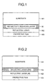
- Fig. 1 is a side view of an optical recording medium according to an embodiment of the present invention.
- the optical recording medium includes a substrate 101 having phase pits thereon, a reflective layer 102, a protective film 103, and a reflectivity reducing layer 10 between the substrate 101 and the reflective layer 102.
- the reflectivity can be set to any value without increasing the transmittance of the optical recording medium.
- a light beam can be incident on the reflective layer 102 either from the substrate 101 or from the protective film 103.
- the reflective layer 102 is a metal film such as aluminum (Al).
- the reflectivity reducing layer 10 is a dielectric film of silicon nitride (SiN), etc. or a metal film that has a higher refractive index than the metal film used as the reflective layer 102.
- the thickness of the reflective layer 102 is adjusted to set the reflectivity of the optical recording medium to an arbitrary value.
- the reflective layer 102 is made thinner to reduce the reflectivity, a slight change in the thickness can cause a sudden fall in the reflectivity.
- the degree of the reflectivity depends on the thickness of the reflective layer 102, and therefore, it is necessary to form the reflective layer 102 in a multi-level manner and to strictly control the thickness at each level so that the reflectivity can be set to any value.
- the thickness of the reflective layer 102 is not proportional to the reflectivity. Hence, it is difficult to strictly control the thickness in the process of forming the reflective layer 102.
- the optical position sensor In an in-vehicle optical disk playback device, for example, the optical position sensor generally detects the position of the optical recording medium when it is being delivered to a spindle motor section. If the optical recording medium has high transmittance, the optical position sensor detects the position of the optical recording medium inaccurately.
- the reflectivity reducing layer 10 is provided in addition to the reflective layer 102.
- the reflectivity of the entire optical recording medium is adjusted.
- an optical recording medium with arbitrary reflectivity can be obtained without having to strictly control the thickness of the reflective layer 102 and the reflectivity reducing layer 10.
- the thickness is selected for the reflectivity reducing layer 10 such that there is only a mild change in the reflectivity due to a variation in the thickness. Consequently, even if there is a variation in the thickness in the fabrication process, a reflectivity standard required for test medium can be maintained constant.
- the optical recording medium as a test medium in which a dielectric layer functions is used as the reflectivity reducing layer 10 is described with reference to Figs. 2 to 6.
- a test medium in which a metal layer is used as the reflectivity reducing layer 10 is described with reference to Figs. 7 to 9.
- reproduction is performed in a wavelength range of 650 nm to 830 nm, i.e., wavelengths for CD-R and DVD-R.
- reproduction is performed at a wavelength of 405 nm, i.e., wavelength for Blu-ray Disk.
- Fig. 2 is a side view of the optical recording medium in which a dielectric layer 10a is provided as the reflectivity reducing layer 10.
- the dielectric layer 10a of silicon nitride (SiN) is formed by sputtering on the substrate 101 with the phase pits formed thereon.
- the reflective layer 102 of aluminum (Al) is formed on the dielectric layer 10a.
- the protective film 103 of protective resin coating is formed on the reflective layer 102.
- the substrate 101 having the phase pits is placed in a vacuum chamber, and a mixture of argon (Ar) gas and nitrogen (N 2 ) gas is introduced into the vacuum chamber.
- the refractive index of the silicon nitride (SiN) layer (dielectric layer 10a) can be varied by changing the flow rate of nitrogen (N 2 ) gas.
- the thickness of the silicon nitride (SiN) layer (dielectric layer 10a) can be varied by changing duration of film formation.
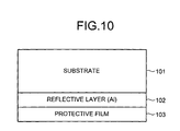
- FIG. 10 is a side view of the conventional optical recording medium having the reflective layer 102 of aluminum (Al).
- the reflective layer 102 of aluminum (A1) is formed on the substrate 101 with phase pits formed thereon, and the protective film 103 of protective resin coating is formed on the reflective layer 102.
- the reflective layer 102 is formed by sputtering.
- the protective film 103 is formed by spin coating of a UV-cured resin and then hardening the resin by UV radiation.
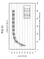
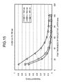
- Fig. 11 is a graph of a relation between the thickness of the reflective layer 102 and the reflectivity in the optical recording medium shown in Fig. 10.
- the reflectivity it is preferable to set the reflectivity between 60% and 80% to reproduce the variation in the reflectivity of CD-R or DVD-R.
- the thickness of the reflective layer 102 is set between 18 nm and 30 nm, the reflectivity can be set between 60% and 80%.
- the reflectivity changes drastically according to the variation in the thickness. Consequently, the reflectivity tends to vary if there is any manufacturing variation, or any change in the thickness or the film quality due to degradation.
- the thickness generally varies around ⁇ 10% due to manufacturing variation, if the thickness of the reflective layer 102 varies by ⁇ 10%, the reflectivity varies to the extent of ⁇ 6%.
- Fig. 12 is a graph of a relation between the thickness of the reflective layer 102 and the transmittance in the optical recording medium shown in Fig. 10. As can be seen in Fig. 10, when the thickness of the reflective layer 102 reduces, there is a sudden rise in the transmittance.
- the desired reflectivity can be obtained by changing the refractive index of the dielectric layer 10a.
- the reflectivity can be stably set to any value without increasing the transmittance of the optical recording medium.
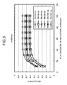
- Fig. 3 is a graph of a relation between the thickness of the dielectric layer 10a, the thickness of the reflective layer 102, and the reflectivity in the optical recording medium shown in Fig. 2.
- the refractive index of the dielectric layer 10a is 2.3
- the thickness of the reflective layer 102 and that of the dielectric layer 10a are changed to indicate the reflectivity according to the change.
- a test medium is obtained that has stable reflectivity when the thickness of the reflective layer 102 is 30 nm, preferably, 40 nm or more, even if there is a variation in the thickness of the reflective layer 102.
- Fig. 4 is a graph of a relation between the thickness of the dielectric layer 10a, the thickness of the reflective layer 102, and the transmittance in the optical recording medium shown in Fig. 2.
- the transmittance can be kept stable at 30% or less by the reflective layer 102 with a thickness of 30 nm, preferably, 40 nm or more.
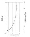
- Fig. 5 is a graph of a relation between the flow rate of nitrogen (N 2 ) gas used when the dielectric layer 10a shown in Fig. 2 is formed and the refractive index of the silicon nitride (SiN) layer (dielectric layer 10a).
- the flow rate of nitrogen (N 2 ) gas shown in Fig. 5 refers to the flow rate of nitrogen (N 2 ) gas mixed with Argon (Ar) gas that is introduced into the vacuum chamber in which the substrate 101 having the phase pits has been placed.
- Ar Argon
- the refractive index tends to decrease.
- the silicon nitride (SiN) layer (dielectric layer 10a) having a refractive index of 2.5 can be obtained.
- Fig. 6 is a graph of a relation between the refractive index of the dielectric layer 10a, the thickness of the dielectric layer 10a, and the reflectivity in the optical recording medium shown in Fig. 2.
- the reflectivity shown in Fig. 6 is the one when the reflective layer 102 of aluminum (Al) of Fig. 2 has a thickness of 60 nm.
- a refractive index is 2.3 and the thickness of the dielectric layer 10a is 70 nm
- a reflectivity of 60% is obtained.
- the same reflectivity, 60% can be obtained with a refractive index of 2.8 and the dielectric layer 10a having a thickness of 35 nm.
- the stability of the test medium is lost because the reflectivity fluctuates significantly according to variation in the thickness of the dielectric layer 10a. Therefore, stable reflectivity in the range of 60% to 70% can be obtained by selecting a refractive index that produces the least variation in the reflectivity in response to the variation in the thickness of the dielectric layer 10a.
- the following procedure can be used to set reflectivity in the range of 70% to 80%.
- a refractive index of 2 is selected, and the thickness of the dielectric layer 10a is changed in the range of 70 nm to 30 nm.
- the stability of the test medium is lost because the reflectivity fluctuates significantly according to variation in the thickness of the dielectric layer 10a.
- the optical recording medium as a test medium performs reproduction in a wavelength range of 650 nm to 830 nm, i.e., wavelengths for CD-R or a DVD-R.
- the optical recording medium as a test medium performs reproduction at a wavelength of 405 nm, i.e., wavelength for Blu-ray disk.
- the reflectivity reducing layer 10 is a metal layer.
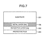
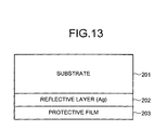
- Fig. 7 is a side view of the optical recording medium having a metal layer as the reflectivity reducing layer 10.
- the optical recording medium includes a substrate 201 with phase pits, a metal layer 10b of molybdenum (Mo) on the substrate 201, a reflective layer 202 of a silver (Ag) film on the metal layer 10b, and a film 203 of protective resin coating formed on the reflective layer 202.
- the metal layer 10b can be composed of any material having a refractive index higher than the metal forming the reflective layer 202.
- FIG. 13 is a side view of the conventional optical recording medium having the reflective layer 202 of silver (Ag).
- Silver (Ag) is used instead of aluminum (Al) for the reflective layer 202 of a Blu-ray Disk that uses a short wavelength to ensure the flatness of the recording surface.
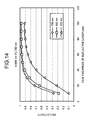
- Fig. 14 is a graph of a relation between the thickness of the reflective layer 202 and the reflectivity in the optical recording medium shown in Fig. 13.
- the line joining the points represented by triangles denotes the variation in the reflectivity of the Blu-ray Disk.
- the lines denoting variations in the reflectivity for the wavelengths used by CD-R and DVD-R are also shown in Fig. 14 for comparison.
- the reflectivity it is preferable to set the reflectivity between 60% and 80% to reproduce the variation in the reflectivity of Blu-ray disk.
- the thickness of the reflective layer 202 is set between 35 nm and 50 nm, the reflectivity can be set between 60% and 80%.
- the variation in the reflectivity for a wavelength of 405 nm is moderate compared to a wavelength of 650 nm or 780 nm.
- Fig. 15 is a graph of a relation between the thickness of the reflective layer 202 and the transmittance in the optical recording medium shown in Fig. 13. As can be seen in Fig. 15, in the thickness range of 35 nm to 50 nm, the transmittance for the wavelength 405 is higher than that of the wavelengths 650 and 780.
- the reflectivity can be stably set to any value without increasing the transmittance of the optical recording medium.
- the optical recording medium shown in Fig. 7 is described next in further detail.
- Fig. 8 is a graph of a relation between the thickness of the metal layer 10b, the thickness of the reflective layer 202, and the reflectivity in the optical recording medium shown in Fig. 7.
- the wavelength is 405
- the thickness of the reflective layer 202 and that of the metal layer 10b are changed to indicate the reflectivity according to the change.
- Fig. 9 is a graph of a relation between the thickness of the metal layer 10b, the thickness of the reflective layer 202, and the transmittance in the optical recording medium shown in Fig. 7. As can be seen in Fig. 9, the transmittance can be kept stable at 15% or less by the reflective layer 202 with a thickness of 60 nm or more.
- a test medium with a stable reflectivity can be obtained in which the transmittance is kept from increasing.
- phase pits formed in the substrate are explained next with reference to Figs. 6 and 7.
- the phase pits are formed by an exposure process involving irradiating a resist substrate with a laser beam.
- the substrate with the phase pits formed thereon is called a stamper.
- the stamper is mounted on a molding machine to mass-produce optical recording media having pits of the same shape.
- the optical recording medium produced using the stamper can be used as a test medium.
- the optical recording medium in which the distortion of the reproduction waveform due to variations in record mark shape as a result of variations in the recording conditions is reproduced by adjusting the phase pits thereof, the degree of distortion of the reproduction waveform can be made constant.
- a stable testing with good reproduction performance can be achieved.
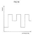
- variation in the reproduction waveform in the optical recording medium is reproduced by changing the time and power for the exposure waveform profile.
- Fig. 16 is a graph of a relation between a power of the light source and exposure time during the exposure process of the stamper fabrication. As can be seen in Fig. 16, distortion in the reproduction waveform as a result of variations in the recording conditions of the optical recording medium can be reproduced by changing the exposure time and the power.
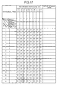
- an orthogonal table shown in Fig. 17 is used to set a plurality of factors for the recording-related variations to reproduce the variation encountered by the optical recording medium in actuality.
- Fig. 17 is an example of the orthogonal table.
- the orthogonal table contains rows in which various standards are set for, for example, the power of the light source and the exposure time, reflectivity, and substrate warp, thickness, and decentering.
- the contribution of each factor producing the recording-related variations can be determined by analyzing distortion tendency of the reproduction waveform of the test medium listed in columns. This analysis data can be used as a guideline for designing a reproducer of the optical recording medium with an improved reproduction quality.
- an optical recording medium that includes a reflective layer that reflects a light beam emitted to a substrate with phase pits thereon and the phase pits
- a reflectivity reducing layer that reduces the reflectivity of the reflective layer is provided on a light-incident side of the reflective layer.
- a dielectric layer is formed as the reflectivity reducing layer where a refractive index is varied.
- a metal layer is formed as the reflectivity reducing layer with a metal film which has a higher refractive index than the metal used for the reflective layer.
- an optical recording medium includes a reflectivity reducing layer that reduces the reflectivity of a reflective layer on a light-incident side of the reflective layer.
- the optical recording medium is fabricated such that the reflectivity of the entire optical recording medium is 60% to 80%, excluding an effect of light scattering by phase bits.
- a dielectric layer is used as the reflectivity reducing layer, and the reflective layer is an aluminum (Al) film mainly containing aluminum, while the dielectric layer is a silicon nitride (SiN) film mainly containing silicon nitride.
- the reflectivity of the entire optical recording medium can be adjusted by changing the thickness or refractive index of the silicon nitride film.
- the reflectivity of the entire optical recording medium can also be adjusted by selecting the refractive index of the silicon nitride film such that the reflectivity is a minimum when the film thickness of the silicon nitride film varies.
- the reflectivity reducing layer a metal layer can also be used which has the refractive index higher than that of the reflective layer.
- the reflective layer is a silver (Ag) film mainly containing silver
- the metal layer is a molybdenum (Mo) film mainly containing molybdenum.
- the reflectivity can be set to any value without increasing a transmission coefficient as well as without having to strictly control the film thickness.
Landscapes
- Engineering & Computer Science (AREA)
- Manufacturing & Machinery (AREA)
- Optical Record Carriers And Manufacture Thereof (AREA)
Applications Claiming Priority (1)
| Application Number | Priority Date | Filing Date | Title |
|---|---|---|---|
| JP2006126811A JP2007299472A (ja) | 2006-04-28 | 2006-04-28 | 光再生媒体および光再生媒体の製造方法 |
Publications (1)
| Publication Number | Publication Date |
|---|---|
| EP1850338A2 true EP1850338A2 (de) | 2007-10-31 |
Family
ID=38353355
Family Applications (1)
| Application Number | Title | Priority Date | Filing Date |
|---|---|---|---|
| EP06117081A Withdrawn EP1850338A2 (de) | 2006-04-28 | 2006-07-12 | Optisches Aufzeichnungsmedium und Herstellungsverfahren dafür |
Country Status (5)
| Country | Link |
|---|---|
| US (1) | US20070253318A1 (de) |
| EP (1) | EP1850338A2 (de) |
| JP (1) | JP2007299472A (de) |
| CN (1) | CN101064139A (de) |
| TW (1) | TW200741690A (de) |
Families Citing this family (3)
| Publication number | Priority date | Publication date | Assignee | Title |
|---|---|---|---|---|
| CN102171381A (zh) * | 2008-09-12 | 2011-08-31 | 布莱阿姆青年大学 | 包含了注入的氧合气体的膜及其制备方法 |
| AU2009292148A1 (en) * | 2008-09-12 | 2010-03-18 | Brigham Young University | Data storage media containing carbon and metal layers |
| TWI478160B (zh) * | 2008-10-23 | 2015-03-21 | Univ Brigham Young | 包含碳層及金屬層之資料儲存媒體及製備光學資訊媒體之方法 |
Family Cites Families (14)
| Publication number | Priority date | Publication date | Assignee | Title |
|---|---|---|---|---|
| JP2968632B2 (ja) * | 1991-03-14 | 1999-10-25 | ティーディーケイ株式会社 | 光磁気記録媒体 |
| JP2983920B2 (ja) * | 1996-06-18 | 1999-11-29 | 三洋電機株式会社 | 互換再生可能なピックアップ調整用光記録媒体およびその調整方法 |
| US6042919A (en) * | 1998-05-07 | 2000-03-28 | Zomax Optical Media, Inc. | Structurally stable optical data storage medium |
| JP2000100008A (ja) * | 1998-09-24 | 2000-04-07 | Fujitsu Ltd | 光磁気記録媒体及び光学ヘッド装置 |
| JP2000229479A (ja) * | 1998-12-09 | 2000-08-22 | Tdk Corp | 光記録媒体 |
| JP3866016B2 (ja) * | 1999-07-02 | 2007-01-10 | Tdk株式会社 | 光情報媒体およびその再生方法 |
| US7050385B2 (en) * | 2000-02-08 | 2006-05-23 | Tosoh Corporation | Optical recording medium |
| WO2004023470A1 (ja) * | 2002-08-30 | 2004-03-18 | Fujitsu Limited | 光磁気記録媒体及び光磁気記録装置 |
| US20040057343A1 (en) * | 2002-09-18 | 2004-03-25 | Matsushita Electric Industrial Co., Ltd. | Magnetic recording medium, method for producing the same and magnetic recording/reproducing apparatus |
| AU2003255916A1 (en) * | 2002-09-18 | 2004-04-08 | Koninklijke Philips Electronics N.V. | A magneto-optical storage medium |
| JP4667721B2 (ja) * | 2003-02-06 | 2011-04-13 | ソニー株式会社 | 光記録媒体およびその製造方法 |
| JP3714331B2 (ja) * | 2003-02-14 | 2005-11-09 | ソニー株式会社 | 光記録媒体、光記録媒体製造用原盤、記録再生装置および記録再生方法 |
| JP2004342216A (ja) * | 2003-05-15 | 2004-12-02 | Sony Corp | 光記録媒体、光記録媒体製造用原盤、記録再生装置および記録再生方法 |
| JPWO2005083696A1 (ja) * | 2004-02-27 | 2007-11-29 | 松下電器産業株式会社 | 磁気記録媒体、その製造方法および製造装置、磁気記録媒体の記録再生方法、および記録再生装置 |
-
2006
- 2006-04-28 JP JP2006126811A patent/JP2007299472A/ja not_active Withdrawn
- 2006-07-12 EP EP06117081A patent/EP1850338A2/de not_active Withdrawn
- 2006-07-17 TW TW095126007A patent/TW200741690A/zh unknown
- 2006-07-28 US US11/495,506 patent/US20070253318A1/en not_active Abandoned
- 2006-08-10 CN CNA2006101154638A patent/CN101064139A/zh active Pending
Also Published As
| Publication number | Publication date |
|---|---|
| TW200741690A (en) | 2007-11-01 |
| CN101064139A (zh) | 2007-10-31 |
| US20070253318A1 (en) | 2007-11-01 |
| JP2007299472A (ja) | 2007-11-15 |
Similar Documents
| Publication | Publication Date | Title |
|---|---|---|
| JP2005071408A (ja) | 光情報記録媒体 | |
| JP2005044395A (ja) | 光情報記録媒体 | |
| JP2005044397A (ja) | 光情報記録媒体 | |
| US6242066B1 (en) | Optical recording medium, optical recording and reproducing apparatus using the same and manufacturing method of optical recording medium | |
| JP2005071403A (ja) | 光情報記録媒体 | |
| JP2005071406A (ja) | 光情報記録媒体 | |
| US8537653B2 (en) | Optical information recording medium and drive device | |
| JP2005071405A (ja) | 光情報記録媒体 | |
| US7803444B2 (en) | Optical disk and method or producing optical disk | |
| EP1850338A2 (de) | Optisches Aufzeichnungsmedium und Herstellungsverfahren dafür | |
| US6844043B2 (en) | Optical disk using groove recording system | |
| US6815032B2 (en) | Optical disc | |
| EP1583084A2 (de) | Verfahren zur optischen Aufzeichnung von Informationen und Vorrichtung zur optischen Aufzeichnung von Informationen | |
| CN101208745B (zh) | 光记录介质 | |
| US6839318B2 (en) | Optical information recording medium having ultraviolet-curing resin and adhesive layers and method of manufacturing same | |
| US7288305B2 (en) | Process for manufacturing a recordable optical disk, optical disk and rewritable layer obtained by the process | |
| JP4642312B2 (ja) | 情報記録媒体並びに該情報記録媒体を用いた情報処理装置 | |
| CN101018672A (zh) | 光学记录介质 | |
| JP3852420B2 (ja) | 光記録媒体 | |
| EP1695839A1 (de) | Optisches aufzeichnungsmedium und herstellungsverfahren dafür, sputter-target, verwendung des optischen aufzeichnungsmediums und optische aufzeichnungs-/reproduktionsvorrichtung | |
| CN110603590B (zh) | 只读的光信息记录介质和该光信息记录介质的反射膜形成用溅射靶 | |
| JP4223703B2 (ja) | 相変化型情報記録媒体 | |
| JP2004055117A (ja) | 光記録媒体および光記録方法 | |
| JP2004005947A (ja) | 光記録媒体および光記録方法 | |
| JP2009026430A (ja) | 光情報媒体 |
Legal Events
| Date | Code | Title | Description |
|---|---|---|---|
| PUAI | Public reference made under article 153(3) epc to a published international application that has entered the european phase |
Free format text: ORIGINAL CODE: 0009012 |
|
| AK | Designated contracting states |
Kind code of ref document: A2 Designated state(s): AT BE BG CH CY CZ DE DK EE ES FI FR GB GR HU IE IS IT LI LT LU LV MC NL PL PT RO SE SI SK TR |
|
| AX | Request for extension of the european patent |
Extension state: AL BA HR MK YU |
|
| STAA | Information on the status of an ep patent application or granted ep patent |
Free format text: STATUS: THE APPLICATION HAS BEEN WITHDRAWN |
|
| 18W | Application withdrawn |
Effective date: 20080829 |