EP1850334A1 - Soft magnetic underlayer in magnetic media and soft magnetic alloy based sputter target - Google Patents
Soft magnetic underlayer in magnetic media and soft magnetic alloy based sputter target Download PDFInfo
- Publication number
- EP1850334A1 EP1850334A1 EP06254396A EP06254396A EP1850334A1 EP 1850334 A1 EP1850334 A1 EP 1850334A1 EP 06254396 A EP06254396 A EP 06254396A EP 06254396 A EP06254396 A EP 06254396A EP 1850334 A1 EP1850334 A1 EP 1850334A1
- Authority
- EP
- European Patent Office
- Prior art keywords
- atomic ratio
- nickel
- tungsten
- molybdenum
- chromium
- Prior art date
- Legal status (The legal status is an assumption and is not a legal conclusion. Google has not performed a legal analysis and makes no representation as to the accuracy of the status listed.)
- Withdrawn
Links
- 230000005291 magnetic effect Effects 0.000 title claims abstract description 127
- 229910001004 magnetic alloy Inorganic materials 0.000 title description 50
- PXHVJJICTQNCMI-UHFFFAOYSA-N Nickel Chemical compound [Ni] PXHVJJICTQNCMI-UHFFFAOYSA-N 0.000 claims abstract description 182
- 238000005260 corrosion Methods 0.000 claims abstract description 125
- 230000007797 corrosion Effects 0.000 claims abstract description 125
- 239000011651 chromium Substances 0.000 claims abstract description 94
- 229910045601 alloy Inorganic materials 0.000 claims abstract description 73
- 239000000956 alloy Substances 0.000 claims abstract description 73
- 239000010949 copper Substances 0.000 claims abstract description 73
- 239000003112 inhibitor Substances 0.000 claims abstract description 72
- 239000010955 niobium Substances 0.000 claims abstract description 72
- 239000010936 titanium Substances 0.000 claims abstract description 70
- 229910052759 nickel Inorganic materials 0.000 claims abstract description 61
- 230000005294 ferromagnetic effect Effects 0.000 claims abstract description 59
- WFKWXMTUELFFGS-UHFFFAOYSA-N tungsten Chemical compound [W] WFKWXMTUELFFGS-UHFFFAOYSA-N 0.000 claims abstract description 53
- 229910052721 tungsten Inorganic materials 0.000 claims abstract description 53
- 239000010937 tungsten Substances 0.000 claims abstract description 53
- OKTJSMMVPCPJKN-UHFFFAOYSA-N Carbon Chemical compound [C] OKTJSMMVPCPJKN-UHFFFAOYSA-N 0.000 claims abstract description 50
- 229910052799 carbon Inorganic materials 0.000 claims abstract description 50
- VYZAMTAEIAYCRO-UHFFFAOYSA-N Chromium Chemical compound [Cr] VYZAMTAEIAYCRO-UHFFFAOYSA-N 0.000 claims abstract description 47
- ZOKXTWBITQBERF-UHFFFAOYSA-N Molybdenum Chemical compound [Mo] ZOKXTWBITQBERF-UHFFFAOYSA-N 0.000 claims abstract description 47
- 229910052804 chromium Inorganic materials 0.000 claims abstract description 47
- 229910052750 molybdenum Inorganic materials 0.000 claims abstract description 47
- 239000011733 molybdenum Substances 0.000 claims abstract description 47
- 239000011572 manganese Substances 0.000 claims abstract description 46
- IJGRMHOSHXDMSA-UHFFFAOYSA-N Atomic nitrogen Chemical compound N#N IJGRMHOSHXDMSA-UHFFFAOYSA-N 0.000 claims abstract description 45
- RYGMFSIKBFXOCR-UHFFFAOYSA-N Copper Chemical compound [Cu] RYGMFSIKBFXOCR-UHFFFAOYSA-N 0.000 claims abstract description 37
- 229910052802 copper Inorganic materials 0.000 claims abstract description 37
- 229910052758 niobium Inorganic materials 0.000 claims abstract description 36
- 229910052710 silicon Inorganic materials 0.000 claims abstract description 36
- 239000010703 silicon Substances 0.000 claims abstract description 36
- XUIMIQQOPSSXEZ-UHFFFAOYSA-N Silicon Chemical compound [Si] XUIMIQQOPSSXEZ-UHFFFAOYSA-N 0.000 claims abstract description 35
- GUCVJGMIXFAOAE-UHFFFAOYSA-N niobium atom Chemical compound [Nb] GUCVJGMIXFAOAE-UHFFFAOYSA-N 0.000 claims abstract description 35
- 229910052719 titanium Inorganic materials 0.000 claims abstract description 35
- RTAQQCXQSZGOHL-UHFFFAOYSA-N Titanium Chemical compound [Ti] RTAQQCXQSZGOHL-UHFFFAOYSA-N 0.000 claims abstract description 34
- 239000000758 substrate Substances 0.000 claims abstract description 34
- XAGFODPZIPBFFR-UHFFFAOYSA-N aluminium Chemical compound [Al] XAGFODPZIPBFFR-UHFFFAOYSA-N 0.000 claims abstract description 26
- 229910052715 tantalum Inorganic materials 0.000 claims abstract description 24
- GUVRBAGPIYLISA-UHFFFAOYSA-N tantalum atom Chemical compound [Ta] GUVRBAGPIYLISA-UHFFFAOYSA-N 0.000 claims abstract description 24
- PWHULOQIROXLJO-UHFFFAOYSA-N Manganese Chemical compound [Mn] PWHULOQIROXLJO-UHFFFAOYSA-N 0.000 claims abstract description 23
- 229910052782 aluminium Inorganic materials 0.000 claims abstract description 23
- 229910052748 manganese Inorganic materials 0.000 claims abstract description 23
- 229910052757 nitrogen Inorganic materials 0.000 claims abstract description 23
- 239000010941 cobalt Substances 0.000 claims description 31
- 229910017052 cobalt Inorganic materials 0.000 claims description 31
- GUTLYIVDDKVIGB-UHFFFAOYSA-N cobalt atom Chemical compound [Co] GUTLYIVDDKVIGB-UHFFFAOYSA-N 0.000 claims description 31
- 238000000034 method Methods 0.000 claims description 29
- XEEYBQQBJWHFJM-UHFFFAOYSA-N Iron Chemical compound [Fe] XEEYBQQBJWHFJM-UHFFFAOYSA-N 0.000 claims description 27
- 238000004544 sputter deposition Methods 0.000 claims description 20
- 230000006698 induction Effects 0.000 claims description 7
- 238000004519 manufacturing process Methods 0.000 claims description 6
- 230000035699 permeability Effects 0.000 claims description 6
- 239000010410 layer Substances 0.000 description 70
- 239000010408 film Substances 0.000 description 22
- 230000008569 process Effects 0.000 description 12
- 239000011241 protective layer Substances 0.000 description 6
- XKRFYHLGVUSROY-UHFFFAOYSA-N Argon Chemical compound [Ar] XKRFYHLGVUSROY-UHFFFAOYSA-N 0.000 description 4
- 230000005290 antiferromagnetic effect Effects 0.000 description 4
- 239000007789 gas Substances 0.000 description 4
- 239000010409 thin film Substances 0.000 description 4
- 239000000654 additive Substances 0.000 description 3
- 238000007496 glass forming Methods 0.000 description 3
- 239000000314 lubricant Substances 0.000 description 3
- 239000002667 nucleating agent Substances 0.000 description 3
- 229910001030 Iron–nickel alloy Inorganic materials 0.000 description 2
- 229910052786 argon Inorganic materials 0.000 description 2
- 239000010931 gold Substances 0.000 description 2
- 238000002844 melting Methods 0.000 description 2
- 230000008018 melting Effects 0.000 description 2
- 239000002245 particle Substances 0.000 description 2
- 239000007787 solid Substances 0.000 description 2
- 125000006850 spacer group Chemical group 0.000 description 2
- ZOXJGFHDIHLPTG-UHFFFAOYSA-N Boron Chemical compound [B] ZOXJGFHDIHLPTG-UHFFFAOYSA-N 0.000 description 1
- 229910020598 Co Fe Inorganic materials 0.000 description 1
- 229910020630 Co Ni Inorganic materials 0.000 description 1
- 229910002519 Co-Fe Inorganic materials 0.000 description 1
- 229910002440 Co–Ni Inorganic materials 0.000 description 1
- BQCADISMDOOEFD-UHFFFAOYSA-N Silver Chemical compound [Ag] BQCADISMDOOEFD-UHFFFAOYSA-N 0.000 description 1
- 229910052787 antimony Inorganic materials 0.000 description 1
- WATWJIUSRGPENY-UHFFFAOYSA-N antimony atom Chemical compound [Sb] WATWJIUSRGPENY-UHFFFAOYSA-N 0.000 description 1
- 238000013459 approach Methods 0.000 description 1
- 229910052785 arsenic Inorganic materials 0.000 description 1
- RQNWIZPPADIBDY-UHFFFAOYSA-N arsenic atom Chemical compound [As] RQNWIZPPADIBDY-UHFFFAOYSA-N 0.000 description 1
- 229910052796 boron Inorganic materials 0.000 description 1
- -1 boron (B) Chemical class 0.000 description 1
- 238000013500 data storage Methods 0.000 description 1
- 238000010586 diagram Methods 0.000 description 1
- 229910052732 germanium Inorganic materials 0.000 description 1
- GNPVGFCGXDBREM-UHFFFAOYSA-N germanium atom Chemical compound [Ge] GNPVGFCGXDBREM-UHFFFAOYSA-N 0.000 description 1
- PCHJSUWPFVWCPO-UHFFFAOYSA-N gold Chemical compound [Au] PCHJSUWPFVWCPO-UHFFFAOYSA-N 0.000 description 1
- 229910052737 gold Inorganic materials 0.000 description 1
- 229910052735 hafnium Inorganic materials 0.000 description 1
- VBJZVLUMGGDVMO-UHFFFAOYSA-N hafnium atom Chemical compound [Hf] VBJZVLUMGGDVMO-UHFFFAOYSA-N 0.000 description 1
- 229910052742 iron Inorganic materials 0.000 description 1
- 230000005381 magnetic domain Effects 0.000 description 1
- 229910052752 metalloid Inorganic materials 0.000 description 1
- 150000002738 metalloids Chemical class 0.000 description 1
- 238000012986 modification Methods 0.000 description 1
- 230000004048 modification Effects 0.000 description 1
- 229910000510 noble metal Inorganic materials 0.000 description 1
- TWNQGVIAIRXVLR-UHFFFAOYSA-N oxo(oxoalumanyloxy)alumane Chemical compound O=[Al]O[Al]=O TWNQGVIAIRXVLR-UHFFFAOYSA-N 0.000 description 1
- 238000004663 powder metallurgy Methods 0.000 description 1
- 238000012552 review Methods 0.000 description 1
- VSZWPYCFIRKVQL-UHFFFAOYSA-N selanylidenegallium;selenium Chemical compound [Se].[Se]=[Ga].[Se]=[Ga] VSZWPYCFIRKVQL-UHFFFAOYSA-N 0.000 description 1
- 229910052709 silver Inorganic materials 0.000 description 1
- 239000004332 silver Substances 0.000 description 1
- 238000005478 sputtering type Methods 0.000 description 1
- 229910052714 tellurium Inorganic materials 0.000 description 1
- PORWMNRCUJJQNO-UHFFFAOYSA-N tellurium atom Chemical compound [Te] PORWMNRCUJJQNO-UHFFFAOYSA-N 0.000 description 1
- 230000007704 transition Effects 0.000 description 1
- LEONUFNNVUYDNQ-UHFFFAOYSA-N vanadium atom Chemical compound [V] LEONUFNNVUYDNQ-UHFFFAOYSA-N 0.000 description 1
Images


Classifications
-
- G—PHYSICS
- G11—INFORMATION STORAGE
- G11B—INFORMATION STORAGE BASED ON RELATIVE MOVEMENT BETWEEN RECORD CARRIER AND TRANSDUCER
- G11B5/00—Recording by magnetisation or demagnetisation of a record carrier; Reproducing by magnetic means; Record carriers therefor
- G11B5/127—Structure or manufacture of heads, e.g. inductive
- G11B5/1278—Structure or manufacture of heads, e.g. inductive specially adapted for magnetisations perpendicular to the surface of the record carrier
-
- C—CHEMISTRY; METALLURGY
- C23—COATING METALLIC MATERIAL; COATING MATERIAL WITH METALLIC MATERIAL; CHEMICAL SURFACE TREATMENT; DIFFUSION TREATMENT OF METALLIC MATERIAL; COATING BY VACUUM EVAPORATION, BY SPUTTERING, BY ION IMPLANTATION OR BY CHEMICAL VAPOUR DEPOSITION, IN GENERAL; INHIBITING CORROSION OF METALLIC MATERIAL OR INCRUSTATION IN GENERAL
- C23C—COATING METALLIC MATERIAL; COATING MATERIAL WITH METALLIC MATERIAL; SURFACE TREATMENT OF METALLIC MATERIAL BY DIFFUSION INTO THE SURFACE, BY CHEMICAL CONVERSION OR SUBSTITUTION; COATING BY VACUUM EVAPORATION, BY SPUTTERING, BY ION IMPLANTATION OR BY CHEMICAL VAPOUR DEPOSITION, IN GENERAL
- C23C14/00—Coating by vacuum evaporation, by sputtering or by ion implantation of the coating forming material
- C23C14/02—Pretreatment of the material to be coated
- C23C14/024—Deposition of sublayers, e.g. to promote adhesion of the coating
- C23C14/025—Metallic sublayers
-
- C—CHEMISTRY; METALLURGY
- C23—COATING METALLIC MATERIAL; COATING MATERIAL WITH METALLIC MATERIAL; CHEMICAL SURFACE TREATMENT; DIFFUSION TREATMENT OF METALLIC MATERIAL; COATING BY VACUUM EVAPORATION, BY SPUTTERING, BY ION IMPLANTATION OR BY CHEMICAL VAPOUR DEPOSITION, IN GENERAL; INHIBITING CORROSION OF METALLIC MATERIAL OR INCRUSTATION IN GENERAL
- C23C—COATING METALLIC MATERIAL; COATING MATERIAL WITH METALLIC MATERIAL; SURFACE TREATMENT OF METALLIC MATERIAL BY DIFFUSION INTO THE SURFACE, BY CHEMICAL CONVERSION OR SUBSTITUTION; COATING BY VACUUM EVAPORATION, BY SPUTTERING, BY ION IMPLANTATION OR BY CHEMICAL VAPOUR DEPOSITION, IN GENERAL
- C23C14/00—Coating by vacuum evaporation, by sputtering or by ion implantation of the coating forming material
- C23C14/06—Coating by vacuum evaporation, by sputtering or by ion implantation of the coating forming material characterised by the coating material
- C23C14/14—Metallic material, boron or silicon
-
- C—CHEMISTRY; METALLURGY
- C23—COATING METALLIC MATERIAL; COATING MATERIAL WITH METALLIC MATERIAL; CHEMICAL SURFACE TREATMENT; DIFFUSION TREATMENT OF METALLIC MATERIAL; COATING BY VACUUM EVAPORATION, BY SPUTTERING, BY ION IMPLANTATION OR BY CHEMICAL VAPOUR DEPOSITION, IN GENERAL; INHIBITING CORROSION OF METALLIC MATERIAL OR INCRUSTATION IN GENERAL
- C23C—COATING METALLIC MATERIAL; COATING MATERIAL WITH METALLIC MATERIAL; SURFACE TREATMENT OF METALLIC MATERIAL BY DIFFUSION INTO THE SURFACE, BY CHEMICAL CONVERSION OR SUBSTITUTION; COATING BY VACUUM EVAPORATION, BY SPUTTERING, BY ION IMPLANTATION OR BY CHEMICAL VAPOUR DEPOSITION, IN GENERAL
- C23C14/00—Coating by vacuum evaporation, by sputtering or by ion implantation of the coating forming material
- C23C14/22—Coating by vacuum evaporation, by sputtering or by ion implantation of the coating forming material characterised by the process of coating
- C23C14/34—Sputtering
- C23C14/3407—Cathode assembly for sputtering apparatus, e.g. Target
- C23C14/3414—Metallurgical or chemical aspects of target preparation, e.g. casting, powder metallurgy
-
- G—PHYSICS
- G11—INFORMATION STORAGE
- G11B—INFORMATION STORAGE BASED ON RELATIVE MOVEMENT BETWEEN RECORD CARRIER AND TRANSDUCER
- G11B5/00—Recording by magnetisation or demagnetisation of a record carrier; Reproducing by magnetic means; Record carriers therefor
- G11B5/62—Record carriers characterised by the selection of the material
- G11B5/64—Record carriers characterised by the selection of the material comprising only the magnetic material without bonding agent
- G11B5/65—Record carriers characterised by the selection of the material comprising only the magnetic material without bonding agent characterised by its composition
-
- G—PHYSICS
- G11—INFORMATION STORAGE
- G11B—INFORMATION STORAGE BASED ON RELATIVE MOVEMENT BETWEEN RECORD CARRIER AND TRANSDUCER
- G11B5/00—Recording by magnetisation or demagnetisation of a record carrier; Reproducing by magnetic means; Record carriers therefor
- G11B5/62—Record carriers characterised by the selection of the material
- G11B5/64—Record carriers characterised by the selection of the material comprising only the magnetic material without bonding agent
- G11B5/66—Record carriers characterised by the selection of the material comprising only the magnetic material without bonding agent the record carriers consisting of several layers
- G11B5/667—Record carriers characterised by the selection of the material comprising only the magnetic material without bonding agent the record carriers consisting of several layers including a soft magnetic layer
-
- G—PHYSICS
- G11—INFORMATION STORAGE
- G11B—INFORMATION STORAGE BASED ON RELATIVE MOVEMENT BETWEEN RECORD CARRIER AND TRANSDUCER
- G11B5/00—Recording by magnetisation or demagnetisation of a record carrier; Reproducing by magnetic means; Record carriers therefor
- G11B5/84—Processes or apparatus specially adapted for manufacturing record carriers
- G11B5/8404—Processes or apparatus specially adapted for manufacturing record carriers manufacturing base layers
-
- G—PHYSICS
- G11—INFORMATION STORAGE
- G11B—INFORMATION STORAGE BASED ON RELATIVE MOVEMENT BETWEEN RECORD CARRIER AND TRANSDUCER
- G11B5/00—Recording by magnetisation or demagnetisation of a record carrier; Reproducing by magnetic means; Record carriers therefor
- G11B5/84—Processes or apparatus specially adapted for manufacturing record carriers
- G11B5/851—Coating a support with a magnetic layer by sputtering
-
- Y—GENERAL TAGGING OF NEW TECHNOLOGICAL DEVELOPMENTS; GENERAL TAGGING OF CROSS-SECTIONAL TECHNOLOGIES SPANNING OVER SEVERAL SECTIONS OF THE IPC; TECHNICAL SUBJECTS COVERED BY FORMER USPC CROSS-REFERENCE ART COLLECTIONS [XRACs] AND DIGESTS
- Y10—TECHNICAL SUBJECTS COVERED BY FORMER USPC
- Y10S—TECHNICAL SUBJECTS COVERED BY FORMER USPC CROSS-REFERENCE ART COLLECTIONS [XRACs] AND DIGESTS
- Y10S428/00—Stock material or miscellaneous articles
- Y10S428/90—Magnetic feature
-
- Y—GENERAL TAGGING OF NEW TECHNOLOGICAL DEVELOPMENTS; GENERAL TAGGING OF CROSS-SECTIONAL TECHNOLOGIES SPANNING OVER SEVERAL SECTIONS OF THE IPC; TECHNICAL SUBJECTS COVERED BY FORMER USPC CROSS-REFERENCE ART COLLECTIONS [XRACs] AND DIGESTS
- Y10—TECHNICAL SUBJECTS COVERED BY FORMER USPC
- Y10T—TECHNICAL SUBJECTS COVERED BY FORMER US CLASSIFICATION
- Y10T428/00—Stock material or miscellaneous articles
- Y10T428/11—Magnetic recording head
- Y10T428/1157—Substrate composition
Definitions
- the present invention generally relates to sputter targets and magnetic recording media.
- the invention relates to corrosion-resistant soft magnetic alloy based sputter targets, and the use of such targets to deposit a soft magnetic film for application in perpendicular magnetic recording media, and on magnetic recording heads.
- perpendicular magnetic recording by far appears to be the most promising.
- the magnetic data recording layer of the recoding media has its magnetic lines directed perpendicular to the axis of the recording media in perpendicular magnetic recording.
- SUL soft magnetic under-layer
- a single-pole recording head and a corresponding magnetic recording media having a soft underlayer enables write fields in excess of double of that which is available for conventional longitudinal recording. Accordingly, acting as a magnetic mirror, a SUL effectively doubles the recording layer thickness, facilitating stronger read-out signals.
- These soft under layers are magnetically soft (with High magnetic induction (Bs), high permeability ( ⁇ e ), low coercivity (Hc)) alloys, such as alloys of Co, Ni and Fe. Similar magnetically soft layers based on these alloys are also used as components in writer pole and reader sensor elements contained in magnetic recording head designs.
- the present invention solves the foregoing problems by providing corrosion-resistant soft magnetic alloy based sputter targets for use to deposit a corrosion-resistant soft magnetic underlayer in magnetic recording media, and soft magnetic layers on magnetic recording heads, for reliable, high performance perpendicular magnetic recording.
- a magnetic recording medium having a corrosion-resistant soft magnetic underlayer includes a substrate, an underlayer deposited above the substrate, the underlayer being comprised of a magnetically soft alloy containing at least one soft ferromagnetic element and at least one corrosion inhibitor element that is selected from the group consisting of chromium (Cr), tungsten (W), molybdenum (Mo), carbon (C), copper (Cu), nickel (Ni), manganese (Mn), nitrogen (N), titanium (Ti), niobium (Nb), silicon (Si), tantalum (Ta), and aluminum (Al), and a magnetic data recording layer deposited above the underlayer.
- the present invention is a magnetic recording head that includes a writer pole and a reader sensor, wherein the writer pole and the reader sensor include an soft magnetic film disposed above a substrate, the soft magnetic film comprised of a magnetically soft alloy containing at least one soft ferromagnetic element and at least one corrosion inhibitor element that is selected from the group consisting of chromium (Cr), tungsten (W), molybdenum (Mo), carbon (C), copper (Cu), nickel (Ni), manganese (Mn), nitrogen (N), titanium (Ti), niobium (Nb), silicon (Si), tantalum (Ta), and aluminum (Al).
- the present invention is directed to a method of manufacturing a magnetic recording medium, including a first sputtering step of sputtering an underlayer above a substrate from a first sputter target that is comprised of a magnetically soft alloy containing at least one soft ferromagnetic element and at least one corrosion inhibitor element that is selected from the group consisting of chromium (Cr), tungsten (W), molybdenum (Mo), carbon (C), copper (Cu), nickel (Ni), manganese (Mn), nitrogen (N), titanium (Ti), niobium (Nb), silicon (Si), tantalum (Ta), and aluminum (Al), and a second sputtering step of sputtering a magnetic data recording layer above the underlayer from a second sputter target.
- a first sputtering step of sputtering an underlayer above a substrate from a first sputter target that is comprised of a magnetically soft alloy containing at least one soft
- the present invention is directed to a sputter target including a magnetically soft alloy containing at least one soft ferromagnetic element and at least one corrosion inhibitor element that is selected from the group consisting of chromium (Cr), tungsten (W), molybdenum (Mo), carbon (C), copper (Cu), nickel (Ni), manganese (Mn), nitrogen (N), titanium (Ti), niobium (Nb), silicon (Si), tantalum (Ta), and aluminum (Al).
- the invention is directed to a method of manufacturing a magnetic recording head having a writer pole and a reader sensor, the method including a sputtering step of sputtering a magnetically soft film above a substrate deposited on at least one of the writer pole and the reader sensor, the magnetically soft film being sputtered from a sputter target that is comprised of a magnetically soft alloy containing at least one soft ferromagnetic element and at least one corrosion inhibitor element that is selected from the group consisting of chromium (Cr), tungsten (W), molybdenum (Mo), carbon (C), copper (Cu), nickel (Ni), manganese (Mn), nitrogen (N), titanium (Ti), niobium (Nb), silicon (Si), tantalum (Ta), and aluminum (Al).
- the at least one soft ferromagnetic element is preferably selected from the group consisting of cobalt (Co), iron (Fe) and nickel (Ni), and the at least one corrosion inhibitor element is selected from a subset of the above-listed group of inhibitor elements depending on the selected ferromagnetic element.
- the amount of the inhibitor element included in the magnetically soft alloy is limited up to a predetermined limit of atomic ratio, where the predetermined atomic ratio limit is determined according to which soft ferromagnetic element(s) is selected and on which inhibitor element is selected.
- a magnetically soft alloy that has a high saturation magnetic induction (Bs) greater than 0.5 Tesla, a high permeability ( ⁇ e ) of greater than 10.0 at 1KHz, and a low coercivity (Hc) of less than 8000 oestead.
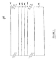
- FIGURE 1 depicts a thin film stack of a recording medium having a soft magnetic underlayer according to one embodiment of the present invention.
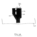
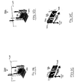
- FIGURES 2A-2E depict recording head components having a soft magnetic film layer according to one embodiment of the present invention.
- FIGURE 3 depicts the sputtering of a soft magnetic film layer onto a recording medium (or recording head component) according to one embodiment of the present invention.
- FIGURE 4 is a flowchart for explaining the method of making a recording medium, or recording head components, having a soft magnetic film layer according to one embodiment of the present invention.
- the invention is generally directed to providing corrosion-resistant soft magnetic alloy based sputter targets for use to deposit a corrosion-resistant soft magnetic film layer as an underlayer in a perpendicular magnetic recording medium stack, and as a magnetically soft film layer on magnetic recording heads, for reliable, high performance magnetic recording.
- corrosion-resistant soft magnetic alloy based sputter targets for use to deposit a corrosion-resistant soft magnetic film layer as an underlayer in a perpendicular magnetic recording medium stack, and as a magnetically soft film layer on magnetic recording heads, for reliable, high performance magnetic recording.
- Figure 1 depicts a magnetic recording medium 100 of the present invention which has a thin film stack including a corrosion-resistant soft magnetic underlayer 104 which was formed during a sputter process using a sputter target according to the present invention.
- magnetic recording medium 100 includes substrate 101 1 and corrosion-resistant soft magnetic underlayer 104.
- Layer 102 which is optional, can include one or more underlayers, anti-ferromagnetic layer, or other type of layer which is deposited between substrate 101 and underlayer 104. In alternate aspects of the present invention, layer 102 is omitted.
- optional layer(s) 105 is optionally provided in the thin film stack in order to optionally provide additional layers, such as a seedlayer or other underlayers, between underlayer 104 and recording layer 106. In alternate aspects of the present invention, optional layer(s) 105 is omitted.
- underlayer 104 is deposited above the substrate 101, or above intervening optional low-level layers 102.
- Underlayer 104 is comprised of a corrosion-resistant soft magnetic alloy, as discussed in more detail herein.
- magnetic recording medium 100 includes magnetic data recording layer 106 deposited above underlayer 104.
- Magnetic recording medium 100 further includes optional protective layer 107, which can be optionally provided and which can include one or more layers such as a carbon (C) overcoat or a lubricant layer, although in alternate aspects protective layer 107 is omitted.
- Magnetic data recording layer 106 has magnetic lines that are perpendicular to the plane of substrate 101.
- underlayer 104 has magnetic lines that are in the plane of substrate 101, thereby creating a magnetic loop with magnetic data recording layer 106.
- underlayer 104 of the present invention enables magnetic recording medium 100 to achieve reliable, high performance perpendicular magnetic recording (PMR) during operation of magnetic recording medium 100.
- Underlayer 104 acts as a magnetic mirror and effectively doubles the thickness of magnetic data recording layer 106, resulting in stronger readout signals from magnetic recording medium 100.
- underlayer 104 is comprised of a corrosion-resistant soft magnetic alloy, which contains at least one or more soft ferromagnetic element, and at least one corrosion inhibitor element.
- the soft ferromagnetic element(s) in the soft magnetic alloy is preferably one of, or any combination of, cobalt (Co), iron (Fe) and nickel (Ni), although other soft ferromagnetic elements can also be included in the soft magnetic alloy.
- the soft magnetic alloy also contains one or more corrosion inhibitor elements which are selected based on the soft ferromagnetic element(s) selected to be in the soft magnetic alloy. This is because some corrosion inhibitor elements are effective to resist corrosion in an alloy having certain selected soft ferromagnetic elements but not others.
- Table 1 provides a list of corrosion inhibitor elements that can be used in the present invention to form the corrosion-resistant soft magnetic alloy used in conjunction with one or more of soft ferromagnetic elements cobalt (Co), iron (Fe) and nickel (Ni).
- the set of corrosion inhibitor elements that can be effectively used with each of the soft ferromagnetic elements are different, because some corrosion inhibitor elements work effectively with some soft ferromagnetic elements but not with others.
- the corrosion-resistant soft magnetic alloy includes one or more of soft ferromagnetic elements cobalt (Co), iron (Fe) and nickel (Ni) and one or more of the corrosion inhibitor elements from the list in Table 1 corresponding to each ferromagnetic element included in the alloy.
- the alloy contains cobalt (Co)
- one or more of corrosion inhibitor elements chromium (Cr), tungsten (W), molybdenum (Mo), carbon (C), copper (Cu), and nickel (Ni) is selected to include in the alloy to provide corrosion resistant properties for the cobalt (Co) in the alloy.
- each one of the listed corrosion inhibitor elements is associated with an upper limit of percentage of atomic ratio. This represents the upper limit of atomic ratio with respect to the corresponding ferromagnetic element for the amount of the particular corrosion inhibitor element included in the alloy.
- an alloy containing cobalt (Co) along with the selected corrosion inhibitor element of tungsten (W) could have up to 15% of tungsten (W) by atomic ratio with respect to the amount of cobalt (Co) in the alloy.
- the alloy contains one million atoms of cobalt (Co)
- up to 150,000 atoms of tungsten (W) could be in the alloy.
- the upper limits are provided for the corrosion inhibitor elements in association with each of the soft ferromagnetic elements because the effectiveness of a corrosion inhibitor element is not increased when the corrosion inhibitor element is added into the alloy beyond that upper limit, and because the addition of the corrosion inhibitor element beyond the upper limit may affect the soft magnetic properties of the alloy.
- the corrosion inhibitor elements listed in Table 1 are different for each of the corresponding soft ferromagnetic elements cobalt (Co), iron (Fe) and nickel (Ni).
- the present invention provides combinations of soft magnetic alloys that can be used in underlayer 104 of magnetic recording medium 100, and for making sputter targets which are used to make underlayer 104.
- the alloy contains iron (Fe), then one or more of corrosion inhibitor elements chromium (Cr), tungsten (W), molybdenum (Mo), carbon (C), nickel (Ni), manganese (Mn), nitrogen (N), titanium (Ti), niobium (Nb), and silicon (Si) is selected to include in the alloy to provide corrosion resistant properties for the cobalt (Fe) in the alloy.
- corrosion inhibitor elements chromium (Cr), tungsten (W), molybdenum (Mo), carbon (C), nickel (Ni), manganese (Mn), nitrogen (N), titanium (Ti), niobium (Nb), and silicon (Si) is selected to include in the alloy to provide corrosion resistant properties for the cobalt (Fe) in the alloy.
- the alloy contains nickel (Ni), then one or more of corrosion inhibitor elements chromium (Cr), tungsten (W), molybdenum (Mo), carbon (C), copper (Cu).
- Cr chromium
- W tungsten
- Mo molybdenum
- carbon C
- Cu copper
- Al tantalum
- Ti titanium
- Ti niobium
- Si silicon
- the corrosion-resistant soft magnetic alloy of the present invention can also be comprised of two or more of soft ferromagnetic elements cobalt (Co), iron (Fe) and nickel (Ni).
- the corrosion-resistant soft magnetic alloy can be a Co-Fe alloy, a Co-Ni alloy or a Co-Fe-Ni alloy, or any other possible combination of soft ferromagnetic elements cobalt (Co), iron (Fe) and nickel (Ni).
- one or more of the corrosion inhibitor elements can be selected from the respective column of Table 1 corresponding to each of the soft ferromagnetic elements included in the alloy.
- the amount of the selected corrosion inhibitor elements could can be included up to the atomic ratio limit provided in the column with respect to the amount of the ferromagnetic element for that column included in the alloy.
- tungsten can be used for all three ferromagnetic elements cobalt (Co), iron (Fe) and nickel (Ni) in the case of a Co-Fe-Ni alloy.
- the amount of tungsten (W) included in the alloy could include a separate amount of tungsten (W) up to the atomic ratio limit provided in Table 1 for each of cobalt (Co), iron (Fe) and nickel (Ni). In this manner, the desired soft magnetic properties of the soft magnetic alloy are maintained, and the appropriate amount of corrosion resistance is included in the alloy.
- the corrosion resistant soft magnetic alloy provided for underlayer 104 of the present invention has a high saturation magnetic induction (Bs) greater than 0.5 Tesla, and has soft magnetic behavior with a high permeability ( ⁇ e ) of greater than 10.0 at 1KHz, and with a low coercivity (Hc) of less than 8000 oestead.
- the corrosion resistant soft magnetic alloy of underlayer 104 can also include other elements in addition to one or more of the soft ferromagnetic elements cobalt (Co), iron (Fe) and nickel (Ni), and one or more of the corrosion inhibitor elements listed in Table 1.
- the underlayer 104 of the present invention is either in a nanocrystalline form or an amorphous form. Accordingly, it may be desirable to include one or more nucleating agent to the corrosion resistant soft magnetic alloy in order to obtain nanocrystalline form in the soft magnetic alloy film of underlayer 104.
- nucleating agents can include one or more of the noble metals, such as copper (Cu), silver (Ag), and gold (Au), for example.
- glass-forming additives to the corrosion resistant soft magnetic alloy in order to obtain an amorphous form in the soft magnetic alloy film of underlayer 104.
- underlayer 104 it is possible for underlayer 104 to be comprised of a single magnetic domain.
- glass-forming additives can include one or more of the early transition elements, such as zirconium (Zr), hafnium (Hf), vanadium (V), tantalum (Ta), and niobium (Nb), for example, and the metalloids, such as boron (B), silicon (Si), germanium (Ge), arsenic (As), antimony (Sb), and tellurium (Te), for example.
- Known methods can be used to include one or more of such nucleating agents or glass-forming additives into the alloy.
- the corrosion resistant soft magnetic alloy discussed above with respect to underlayer 104 of magnetic recording medium 100 can also be used to form a soft magnetic film layer in the components of a recording head for increased performance in a perpendicular magnetic recording (PMR) head.
- PMR perpendicular magnetic recording
- FIG. 2A depicts a perpendicular magnetic recording (PMR) head 200 which includes writer pole 210 according to an embodiment of the present invention.
- writer pole 210 includes several layers 211 to 214.
- writer pole 210 has substrate 211 which is preferably a baked photo-resist layer.
- a soft magnetic film layer 213 is deposited above substrate 211, according to the invention.
- Writer pole 210 also includes copper elements and layer 212 and alloy layer 214, which is preferably an aluminum oxide layer. It should be appreciated that the layers shown for writer pole are exemplary, and that layers 211, 212 and 214 can be comprised of other elements and/or alloys.
- soft magnetic film layer 213 is deposited above the substrate 211, and is comprised of a corrosion-resistant soft magnetic alloy, as described above with respect to the corrosion-resistant soft magnetic alloy of underlayer 104 of magnetic recording medium 100 shown in Figure 1. Accordingly, the reader is referred to the above discussion of Figure 1, and Table 1, for a description of the corrosion-resistant soft magnetic alloy that is also used for soft magnetic film layer 213 of writer pole 210.
- FIGs 2B illustrates reader sensor 220 as a component of recording head 200, although reader sensor 220 can be separately provided in other alternative embodiments.
- reader sensor 220 has a sensor unit 221 which has current applied to it in operation in order to read the magnetic segments of medium 230.
- Figure 2C shows the layer stack of sensor unit 221 shown in Figure 2B.
- sensor unit 221 is seen to include antiferromagnetic layer 222, free ferromagnet layer 223, spacer layer 224, and soft adjacent layer 225.
- free ferromagnet layer 223 and soft adjacent layer 225 are a soft magnetic film layer which is comprised of a corrosion-resistant soft magnetic alloy, as described above with respect to the corrosion-resistant soft magnetic alloy of underlayer 104 of magnetic recording medium 100 shown in Figure 1.
- sensor unit 221 is an efficient and corrosion resistant in operation.
- FIGs 2D illustrates another embodiment of reader sensor 220 as a component of recording head 200, although reader sensor 220 can be separately provided in other alternative embodiments.
- reader sensor 220 has a sensor unit 221 which has current applied to it in operation in order to read the magnetic segments of medium 230.
- Figure 2E shows the layer stack of sensor unit 221 shown in Figure 2D.
- sensor unit 221 is seen to include antiferromagnetic layer 222, free ferromagnet layer 223, spacer layer 224, and pinned ferromagnetic layer 225.
- free ferromagnet layer 223 and pinned ferromagnetic layer 225 are a soft magnetic film layer which is comprised of a corrosion-resistant soft magnetic alloy, as described above with respect to the corrosion-resistant soft magnetic alloy of underlayer 104 of magnetic recording medium 100 shown in Figure 1.
- sensor unit 221 is an efficient and corrosion resistant in operation.
- sensor unit 221 can also optionally include a protective layer (not shown), which can be one or more layers such as a carbon (C) overcoat or a lubricant layer.
- FIG 3 is a graphic diagram that depicts the sputtering of a corrosion resistant soft magnetic alloy film onto a recording medium (or onto a recording head component) according to the present invention.
- substrate 300 is shown which can be the substrate of a magnetic medium, such as magnetic recording medium 100, or the substrate of a recording head component, such as writer pole 210 or reader sensor 220 of recording head 200.
- a corrosion resistant soft magnetic alloy film is being applied as an underlayer 301 onto substrate 300 of a recording medium by a sputtering process.
- known types of sputtering processes and equipment can be used in order to apply the corrosion resistant soft magnetic alloy film of the invention to create underlayer 301.
- the simplified depiction of a sputtering process shown in Figure 3 is for explanatory purposes, and other sputtering processes and equipment can be used to practice the invention without detracting from or limiting the scope of the invention.
- sputter target 310 is provided, which is comprised of a corrosion-resistant soft magnetic alloy, as described above with respect to the corrosion-resistant soft magnetic alloy of underlayer 104 of magnetic recording medium 100 shown in Figure 1. Accordingly, the reader is referred to the above discussion of Figure 1, and Table 1, for a description of the corrosion-resistant soft magnetic alloy that makes up sputter target 310.
- Sputter target 310 can be round, square, rectangular, or any number of other shapes, such as solid or hollow cylindrical, or nearly any other shape.
- Sputter target 310 is formed of the corrosion-resistant soft magnetic alloy of the present invention according to any of several known processes, such as induction melting, ingot gas melting, and powder metallurgy, for example.
- sputter target 310 comprised of the corrosion-resistant soft magnetic alloy described above with respect to Figure 1 and Table 1, is electrically grounded. In contrast, a positive electrical charge is applied to substrate 300.
- a cloud of ionized Argon gas 305 is shown in Figure 3 disposed between sputter target 310 and substrate 300. Ionized Argon gas 305, having a positive charge, has a velocity vector directed toward the surface of sputter target 310, partially due to the electrical ground applied to sputter target 310. The ionized gas bombards the surface of sputter target 310 and dislodges, or sputters, particles of the corrosion-resistant soft magnetic alloy from sputter target 310.
- These particles of the sputtered corrosion-resistant soft magnetic alloy are ejected away from sputter target 310 and onto the surface of substrate 300, partially due to the positive charge applied to substrate 300. This process is continued until a thin film of the corrosion-resistant soft magnetic alloy having the desired thickness is applied above the surface of substrate 300, thereby forming underlayer 301 above substrate 300.
- other intervening layers can be placed between substrate 300 and underlayer 301, as described above with respect to Figure 1.
- Other known types of sputter targets can be used to sputter other types of layers onto substrate 300, such as a magnetic recording layer in the case of a magnetic data recording medium.
- FIG. 4 is a flowchart for explaining the steps of one exemplary embodiment of the invention in which a magnetic recording medium is manufactured having an underlayer of corrosion-resistant soft magnetic alloy, and can also be used to generally depict the creation of a corrosion-resistant soft magnetic alloy film in a recording head component.
- the process starts in step 401, and, in step 402, certain low-level layers, such as an anti-ferromagnetic layer, other types of underlayers, are deposited above the substrate using sputtering from one or more sputter targets.
- step 402 is omitted.
- a corrosion resistant soft magnetic alloy underlayer is sputtered above the substrate, or above low level layers if any were applied, from a corrosion resistant soft magnetic alloy sputter target (step 403).
- the corrosion resistant soft magnetic alloy sputter target is comprised of a corrosion-resistant soft magnetic alloy as described above with respect to Figure 1 and Table 1.
- the sputtering process can be that described above with respect to Figure 3, or can be some other known sputtering process.
- step 404 After the corrosion resistant soft magnetic alloy underlayer is applied in step 403, other underlayers or a seed layer may optionally be sputtered above the corrosion resistant soft magnetic alloy underlayer (step 404). At least one magnetic data recording layer is then sputtered above the corrosion resistant soft magnetic alloy underlayer (or above intervening underlayers or seed layer) from a different sputter target. (step 405). An additional protective layer or layers, such as a carbon (C) overcoat and/or a lubricant layer, are sputtered above the magnetic data recording layer in step 406, and the process ends (step 407). In alternate aspects, step 406 is omitted and no protective layer is sputtered onto the magnetic data recording layer. Of course, other steps can be added or omitted from the foregoing exemplary process to manufacture a magnetic recording medium without departing from the scope of the invention.
- C carbon
Abstract
Description
- The present invention generally relates to sputter targets and magnetic recording media. In particular, the invention relates to corrosion-resistant soft magnetic alloy based sputter targets, and the use of such targets to deposit a soft magnetic film for application in perpendicular magnetic recording media, and on magnetic recording heads.
- To satisfy the continual demand for even greater data storage capacities, higher density magnetic recording media are required. Of the approaches to achieve this high data density, perpendicular magnetic recording (PMR) by far appears to be the most promising. In contrast to longitudinal magnetic recording, the magnetic data recording layer of the recoding media has its magnetic lines directed perpendicular to the axis of the recording media in perpendicular magnetic recording. Also, in perpendicular magnetic recording, a higher writing field can be obtained by using a soft magnetic under-layer (SUL) beneath the magnetic data recording layer.
- For example, a single-pole recording head and a corresponding magnetic recording media having a soft underlayer enables write fields in excess of double of that which is available for conventional longitudinal recording. Accordingly, acting as a magnetic mirror, a SUL effectively doubles the recording layer thickness, facilitating stronger read-out signals. These soft under layers are magnetically soft (with High magnetic induction (Bs), high permeability (µe), low coercivity (Hc)) alloys, such as alloys of Co, Ni and Fe. Similar magnetically soft layers based on these alloys are also used as components in writer pole and reader sensor elements contained in magnetic recording head designs.
- Although higher writing fields and performance can be achieved in PMR applications using magnetically soft alloys as described above, such alloys can have a high propensity for corrosion, thereby potentially causing severe reliability issues in both the magnetic recording media and in the recording head during hard disk drive operations.
- The present invention solves the foregoing problems by providing corrosion-resistant soft magnetic alloy based sputter targets for use to deposit a corrosion-resistant soft magnetic underlayer in magnetic recording media, and soft magnetic layers on magnetic recording heads, for reliable, high performance perpendicular magnetic recording.
- In accordance with one embodiment of the present invention, a magnetic recording medium having a corrosion-resistant soft magnetic underlayer is provided. Specifically, a magnetic recording medium is provided that includes a substrate, an underlayer deposited above the substrate, the underlayer being comprised of a magnetically soft alloy containing at least one soft ferromagnetic element and at least one corrosion inhibitor element that is selected from the group consisting of chromium (Cr), tungsten (W), molybdenum (Mo), carbon (C), copper (Cu), nickel (Ni), manganese (Mn), nitrogen (N), titanium (Ti), niobium (Nb), silicon (Si), tantalum (Ta), and aluminum (Al), and a magnetic data recording layer deposited above the underlayer.
- In another embodiment, the present invention is a magnetic recording head that includes a writer pole and a reader sensor, wherein the writer pole and the reader sensor include an soft magnetic film disposed above a substrate, the soft magnetic film comprised of a magnetically soft alloy containing at least one soft ferromagnetic element and at least one corrosion inhibitor element that is selected from the group consisting of chromium (Cr), tungsten (W), molybdenum (Mo), carbon (C), copper (Cu), nickel (Ni), manganese (Mn), nitrogen (N), titanium (Ti), niobium (Nb), silicon (Si), tantalum (Ta), and aluminum (Al).
- According to a further embodiment, the present invention is directed to a method of manufacturing a magnetic recording medium, including a first sputtering step of sputtering an underlayer above a substrate from a first sputter target that is comprised of a magnetically soft alloy containing at least one soft ferromagnetic element and at least one corrosion inhibitor element that is selected from the group consisting of chromium (Cr), tungsten (W), molybdenum (Mo), carbon (C), copper (Cu), nickel (Ni), manganese (Mn), nitrogen (N), titanium (Ti), niobium (Nb), silicon (Si), tantalum (Ta), and aluminum (Al), and a second sputtering step of sputtering a magnetic data recording layer above the underlayer from a second sputter target.
- According to yet another embodiment, the present invention is directed to a sputter target including a magnetically soft alloy containing at least one soft ferromagnetic element and at least one corrosion inhibitor element that is selected from the group consisting of chromium (Cr), tungsten (W), molybdenum (Mo), carbon (C), copper (Cu), nickel (Ni), manganese (Mn), nitrogen (N), titanium (Ti), niobium (Nb), silicon (Si), tantalum (Ta), and aluminum (Al).
- In a further embodiment, the invention is directed to a method of manufacturing a magnetic recording head having a writer pole and a reader sensor, the method including a sputtering step of sputtering a magnetically soft film above a substrate deposited on at least one of the writer pole and the reader sensor, the magnetically soft film being sputtered from a sputter target that is comprised of a magnetically soft alloy containing at least one soft ferromagnetic element and at least one corrosion inhibitor element that is selected from the group consisting of chromium (Cr), tungsten (W), molybdenum (Mo), carbon (C), copper (Cu), nickel (Ni), manganese (Mn), nitrogen (N), titanium (Ti), niobium (Nb), silicon (Si), tantalum (Ta), and aluminum (Al).
- In the above embodiments, the at least one soft ferromagnetic element is preferably selected from the group consisting of cobalt (Co), iron (Fe) and nickel (Ni), and the at least one corrosion inhibitor element is selected from a subset of the above-listed group of inhibitor elements depending on the selected ferromagnetic element. In addition, the amount of the inhibitor element included in the magnetically soft alloy is limited up to a predetermined limit of atomic ratio, where the predetermined atomic ratio limit is determined according to which soft ferromagnetic element(s) is selected and on which inhibitor element is selected.
- In this manner, a magnetically soft alloy is provided that has a high saturation magnetic induction (Bs) greater than 0.5 Tesla, a high permeability (µe) of greater than 10.0 at 1KHz, and a low coercivity (Hc) of less than 8000 oestead.
- Additional features and advantages of the invention will be set forth in the description below, and in part will be apparent from the description, or may be learned by practice of the invention. The objectives and other advantages of the invention will be realized and attained by the structure particularly pointed out in the written description and claims hereof as well as the appended drawings.
- It is to be understood that both the foregoing general description and the following detailed description are exemplary and explanatory and are intended to provide further explanation of the invention as claimed.
- The accompanying drawings, which are included to provide further understanding of the invention and are incorporated in and constitute a part of this specification, illustrate embodiments of the invention and together with the description serve to explain the principles of the invention.
- FIGURE 1 depicts a thin film stack of a recording medium having a soft magnetic underlayer according to one embodiment of the present invention.
- FIGURES 2A-2E depict recording head components having a soft magnetic film layer according to one embodiment of the present invention.
- FIGURE 3 depicts the sputtering of a soft magnetic film layer onto a recording medium (or recording head component) according to one embodiment of the present invention.
- FIGURE 4 is a flowchart for explaining the method of making a recording medium, or recording head components, having a soft magnetic film layer according to one embodiment of the present invention.
- In the following detailed description, numerous specific details are set forth to provide a full understanding of the present invention. It will be apparent, however, to one ordinarily skilled in the art that the present invention may be practiced without some of these specific details. In other instances, well-known structures and techniques have not been shown in detail to avoid unnecessarily obscuring the present invention.
- The invention is generally directed to providing corrosion-resistant soft magnetic alloy based sputter targets for use to deposit a corrosion-resistant soft magnetic film layer as an underlayer in a perpendicular magnetic recording medium stack, and as a magnetically soft film layer on magnetic recording heads, for reliable, high performance magnetic recording. In this manner, magnetic recording media, and magnetic recording head components, are produced having a corrosion-resistant soft magnetic underlayer, resulting in higher write fields and in reliable, corrosion-resistant performance.
- Figure 1 depicts a
magnetic recording medium 100 of the present invention which has a thin film stack including a corrosion-resistant soft magnetic underlayer 104 which was formed during a sputter process using a sputter target according to the present invention. As seen in Figure 1,magnetic recording medium 100 includes substrate 101 1 and corrosion-resistant soft magnetic underlayer 104. Layer 102, which is optional, can include one or more underlayers, anti-ferromagnetic layer, or other type of layer which is deposited between substrate 101 and underlayer 104. In alternate aspects of the present invention, layer 102 is omitted. Similarly, optional layer(s) 105 is optionally provided in the thin film stack in order to optionally provide additional layers, such as a seedlayer or other underlayers, between underlayer 104 and recording layer 106. In alternate aspects of the present invention, optional layer(s) 105 is omitted. - As mentioned above, underlayer 104 is deposited above the substrate 101, or above intervening optional low-level layers 102. Underlayer 104 is comprised of a corrosion-resistant soft magnetic alloy, as discussed in more detail herein. As seen in Figure 1,
magnetic recording medium 100 includes magnetic data recording layer 106 deposited above underlayer 104.Magnetic recording medium 100 further includes optional protective layer 107, which can be optionally provided and which can include one or more layers such as a carbon (C) overcoat or a lubricant layer, although in alternate aspects protective layer 107 is omitted. Magnetic data recording layer 106 has magnetic lines that are perpendicular to the plane of substrate 101. In contrast, underlayer 104 has magnetic lines that are in the plane of substrate 101, thereby creating a magnetic loop with magnetic data recording layer 106. - In this manner, underlayer 104 of the present invention enables
magnetic recording medium 100 to achieve reliable, high performance perpendicular magnetic recording (PMR) during operation ofmagnetic recording medium 100. Underlayer 104 acts as a magnetic mirror and effectively doubles the thickness of magnetic data recording layer 106, resulting in stronger readout signals frommagnetic recording medium 100. Specifically, underlayer 104 is comprised of a corrosion-resistant soft magnetic alloy, which contains at least one or more soft ferromagnetic element, and at least one corrosion inhibitor element. In this regard, the soft ferromagnetic element(s) in the soft magnetic alloy is preferably one of, or any combination of, cobalt (Co), iron (Fe) and nickel (Ni), although other soft ferromagnetic elements can also be included in the soft magnetic alloy. In the present invention, the soft magnetic alloy also contains one or more corrosion inhibitor elements which are selected based on the soft ferromagnetic element(s) selected to be in the soft magnetic alloy. This is because some corrosion inhibitor elements are effective to resist corrosion in an alloy having certain selected soft ferromagnetic elements but not others. - Table 1, below, provides a list of corrosion inhibitor elements that can be used in the present invention to form the corrosion-resistant soft magnetic alloy used in conjunction with one or more of soft ferromagnetic elements cobalt (Co), iron (Fe) and nickel (Ni). As mentioned above, the set of corrosion inhibitor elements that can be effectively used with each of the soft ferromagnetic elements are different, because some corrosion inhibitor elements work effectively with some soft ferromagnetic elements but not with others.
Table 1: Corrosion inhibitors for each soft ferromagnetic element COBALT (Co) ALLOY CORROSION INHIBITORS IRON (Fe) ALLOY CORROSION INHIBITORS NICKEL (Ni) ALLOY CORROSION INHIBITORS Chromium (Cr) (up to 25% atomic ratio) Chromium (Cr) (up to 30% atomic ratio) Chromium (Cr) (up to 30% atomic ratio) Tungsten (W) (up to 15% atomic ratio) Tungsten (W) (up to 5% atomic ratio) Tungsten (W) (up to 4% atomic ratio) Molybdenum (Mo) (up to 10% atomic ratio) Molybdenum (Mo) (up to 5% atomic ratio) Molybdenum (Mo) (up to 28% atomic ratio) Carbon (C) (up to 2% atomic ratio) Carbon (C) (up to 0.3% atomic ratio) Carbon (C) (up to 2% atomic ratio) Copper (Cu) (up to 2% atomic ratio) Nickel (Ni) (up to 30% atomic ratio) Copper (Cu) (up to 3% atomic ratio) Nickel (Ni) (up to 20% atomic ratio) Manganese (Mn) (up to 15% atomic ratio) Aluminum (A1) (up to 2% atomic ratio) - Nitrogen (N) (up to 0.4% atomic ratio) Tantalum (Ta) (up to 10% atomic ratio) - Titanium (Ti) (up to 2% atomic ratio) Titanium (Ti) (up to 2% atomic ratio) - Niobium (Nb) (up to 2% atomic ratio) Niobium (Nb) (up to 10% atomic ratio) - Silicon (Si) (up to 1% atomic ratio) Silicon (Si) (up to 11% atomic ratio) - As seen in Table 1, a list of corrosion inhibitor elements is provided for each one of the soft ferromagnetic elements cobalt (Co), iron (Fe) and nickel (Ni). In the present invention, the corrosion-resistant soft magnetic alloy includes one or more of soft ferromagnetic elements cobalt (Co), iron (Fe) and nickel (Ni) and one or more of the corrosion inhibitor elements from the list in Table 1 corresponding to each ferromagnetic element included in the alloy.
- For example, if the alloy contains cobalt (Co), then one or more of corrosion inhibitor elements chromium (Cr), tungsten (W), molybdenum (Mo), carbon (C), copper (Cu), and nickel (Ni) is selected to include in the alloy to provide corrosion resistant properties for the cobalt (Co) in the alloy. As seen in Table 1, each one of the listed corrosion inhibitor elements is associated with an upper limit of percentage of atomic ratio. This represents the upper limit of atomic ratio with respect to the corresponding ferromagnetic element for the amount of the particular corrosion inhibitor element included in the alloy. For example, an alloy containing cobalt (Co) along with the selected corrosion inhibitor element of tungsten (W) could have up to 15% of tungsten (W) by atomic ratio with respect to the amount of cobalt (Co) in the alloy. In other words, if the alloy contains one million atoms of cobalt (Co), then up to 150,000 atoms of tungsten (W) could be in the alloy. The upper limits are provided for the corrosion inhibitor elements in association with each of the soft ferromagnetic elements because the effectiveness of a corrosion inhibitor element is not increased when the corrosion inhibitor element is added into the alloy beyond that upper limit, and because the addition of the corrosion inhibitor element beyond the upper limit may affect the soft magnetic properties of the alloy.
- As seen in Table 1, the corrosion inhibitor elements listed in Table 1 are different for each of the corresponding soft ferromagnetic elements cobalt (Co), iron (Fe) and nickel (Ni). In this manner, the present invention provides combinations of soft magnetic alloys that can be used in underlayer 104 of
magnetic recording medium 100, and for making sputter targets which are used to make underlayer 104. Turning to the other columns of Table 1, it can be seen that, if the alloy contains iron (Fe), then one or more of corrosion inhibitor elements chromium (Cr), tungsten (W), molybdenum (Mo), carbon (C), nickel (Ni), manganese (Mn), nitrogen (N), titanium (Ti), niobium (Nb), and silicon (Si) is selected to include in the alloy to provide corrosion resistant properties for the cobalt (Fe) in the alloy. - Similarly, if the alloy contains nickel (Ni), then one or more of corrosion inhibitor elements chromium (Cr), tungsten (W), molybdenum (Mo), carbon (C), copper (Cu). aluminum (Al), tantalum (Ta), titanium (Ti), niobium (Nb), and silicon (Si) is selected to include in the alloy to provide corrosion resistant properties for the cobalt (Ni) in the alloy. As mentioned above, the corrosion-resistant soft magnetic alloy of the present invention can also be comprised of two or more of soft ferromagnetic elements cobalt (Co), iron (Fe) and nickel (Ni). For example the corrosion-resistant soft magnetic alloy can be a Co-Fe alloy, a Co-Ni alloy or a Co-Fe-Ni alloy, or any other possible combination of soft ferromagnetic elements cobalt (Co), iron (Fe) and nickel (Ni). In such a case, one or more of the corrosion inhibitor elements can be selected from the respective column of Table 1 corresponding to each of the soft ferromagnetic elements included in the alloy. The amount of the selected corrosion inhibitor elements could can be included up to the atomic ratio limit provided in the column with respect to the amount of the ferromagnetic element for that column included in the alloy.
- It can be appreciated upon review of Table 1 that a same corrosion inhibitor element, such as tungsten (W), can be used for all three ferromagnetic elements cobalt (Co), iron (Fe) and nickel (Ni) in the case of a Co-Fe-Ni alloy. In such an example, the amount of tungsten (W) included in the alloy could include a separate amount of tungsten (W) up to the atomic ratio limit provided in Table 1 for each of cobalt (Co), iron (Fe) and nickel (Ni). In this manner, the desired soft magnetic properties of the soft magnetic alloy are maintained, and the appropriate amount of corrosion resistance is included in the alloy. Specifically, the corrosion resistant soft magnetic alloy provided for underlayer 104 of the present invention has a high saturation magnetic induction (Bs) greater than 0.5 Tesla, and has soft magnetic behavior with a high permeability (µe) of greater than 10.0 at 1KHz, and with a low coercivity (Hc) of less than 8000 oestead.
- The corrosion resistant soft magnetic alloy of underlayer 104 can also include other elements in addition to one or more of the soft ferromagnetic elements cobalt (Co), iron (Fe) and nickel (Ni), and one or more of the corrosion inhibitor elements listed in Table 1. The underlayer 104 of the present invention is either in a nanocrystalline form or an amorphous form. Accordingly, it may be desirable to include one or more nucleating agent to the corrosion resistant soft magnetic alloy in order to obtain nanocrystalline form in the soft magnetic alloy film of underlayer 104. In this regard, such nucleating agents can include one or more of the noble metals, such as copper (Cu), silver (Ag), and gold (Au), for example.
- In the alternative, it may be desirable to include one or more glass-forming additives to the corrosion resistant soft magnetic alloy in order to obtain an amorphous form in the soft magnetic alloy film of underlayer 104. In this manner, it is possible for underlayer 104 to be comprised of a single magnetic domain. Such glass-forming additives can include one or more of the early transition elements, such as zirconium (Zr), hafnium (Hf), vanadium (V), tantalum (Ta), and niobium (Nb), for example, and the metalloids, such as boron (B), silicon (Si), germanium (Ge), arsenic (As), antimony (Sb), and tellurium (Te), for example. Known methods can be used to include one or more of such nucleating agents or glass-forming additives into the alloy.
- The corrosion resistant soft magnetic alloy discussed above with respect to underlayer 104 of
magnetic recording medium 100 can also be used to form a soft magnetic film layer in the components of a recording head for increased performance in a perpendicular magnetic recording (PMR) head. - In this regard, Figure 2A depicts a perpendicular magnetic recording (PMR)
head 200 which includeswriter pole 210 according to an embodiment of the present invention. As seen in Figure 2,writer pole 210 includesseveral layers 211 to 214. Specifically,writer pole 210 hassubstrate 211 which is preferably a baked photo-resist layer. A softmagnetic film layer 213 is deposited abovesubstrate 211, according to the invention.Writer pole 210 also includes copper elements andlayer 212 andalloy layer 214, which is preferably an aluminum oxide layer. It should be appreciated that the layers shown for writer pole are exemplary, and thatlayers - As mentioned above, soft
magnetic film layer 213 is deposited above thesubstrate 211, and is comprised of a corrosion-resistant soft magnetic alloy, as described above with respect to the corrosion-resistant soft magnetic alloy of underlayer 104 ofmagnetic recording medium 100 shown in Figure 1. Accordingly, the reader is referred to the above discussion of Figure 1, and Table 1, for a description of the corrosion-resistant soft magnetic alloy that is also used for softmagnetic film layer 213 ofwriter pole 210. - Figures 2B illustrates reader sensor 220 as a component of
recording head 200, although reader sensor 220 can be separately provided in other alternative embodiments. As shown in Figure 2B, reader sensor 220 has asensor unit 221 which has current applied to it in operation in order to read the magnetic segments ofmedium 230. Figure 2C shows the layer stack ofsensor unit 221 shown in Figure 2B. In this regard,sensor unit 221 is seen to includeantiferromagnetic layer 222,free ferromagnet layer 223,spacer layer 224, and softadjacent layer 225. In this regard, according to this embodiment of the invention,free ferromagnet layer 223 and softadjacent layer 225 are a soft magnetic film layer which is comprised of a corrosion-resistant soft magnetic alloy, as described above with respect to the corrosion-resistant soft magnetic alloy of underlayer 104 ofmagnetic recording medium 100 shown in Figure 1. In this manner,sensor unit 221 is an efficient and corrosion resistant in operation. - Figures 2D illustrates another embodiment of reader sensor 220 as a component of
recording head 200, although reader sensor 220 can be separately provided in other alternative embodiments. As shown in Figure 2D, reader sensor 220 has asensor unit 221 which has current applied to it in operation in order to read the magnetic segments ofmedium 230. Figure 2E shows the layer stack ofsensor unit 221 shown in Figure 2D. In this regard,sensor unit 221 is seen to includeantiferromagnetic layer 222,free ferromagnet layer 223,spacer layer 224, and pinnedferromagnetic layer 225. In this regard, according to this embodiment of the invention,free ferromagnet layer 223 and pinnedferromagnetic layer 225 are a soft magnetic film layer which is comprised of a corrosion-resistant soft magnetic alloy, as described above with respect to the corrosion-resistant soft magnetic alloy of underlayer 104 ofmagnetic recording medium 100 shown in Figure 1. In this manner,sensor unit 221 is an efficient and corrosion resistant in operation. In the embodiments of reader sensor 220 described above in Figures 2B to 2E,sensor unit 221 can also optionally include a protective layer (not shown), which can be one or more layers such as a carbon (C) overcoat or a lubricant layer. - Figure 3 is a graphic diagram that depicts the sputtering of a corrosion resistant soft magnetic alloy film onto a recording medium (or onto a recording head component) according to the present invention. Turning to Figure 3,
substrate 300 is shown which can be the substrate of a magnetic medium, such asmagnetic recording medium 100, or the substrate of a recording head component, such aswriter pole 210 or reader sensor 220 ofrecording head 200. In this regard, a corrosion resistant soft magnetic alloy film is being applied as anunderlayer 301 ontosubstrate 300 of a recording medium by a sputtering process. It should be appreciated that known types of sputtering processes and equipment can be used in order to apply the corrosion resistant soft magnetic alloy film of the invention to createunderlayer 301. The simplified depiction of a sputtering process shown in Figure 3 is for explanatory purposes, and other sputtering processes and equipment can be used to practice the invention without detracting from or limiting the scope of the invention. - As seen in Figure 3,
sputter target 310 is provided, which is comprised of a corrosion-resistant soft magnetic alloy, as described above with respect to the corrosion-resistant soft magnetic alloy of underlayer 104 ofmagnetic recording medium 100 shown in Figure 1. Accordingly, the reader is referred to the above discussion of Figure 1, and Table 1, for a description of the corrosion-resistant soft magnetic alloy that makes upsputter target 310.Sputter target 310 can be round, square, rectangular, or any number of other shapes, such as solid or hollow cylindrical, or nearly any other shape.Sputter target 310 is formed of the corrosion-resistant soft magnetic alloy of the present invention according to any of several known processes, such as induction melting, ingot gas melting, and powder metallurgy, for example. - In the example shown in Figure 3,
sputter target 310, comprised of the corrosion-resistant soft magnetic alloy described above with respect to Figure 1 and Table 1, is electrically grounded. In contrast, a positive electrical charge is applied tosubstrate 300. A cloud ofionized Argon gas 305 is shown in Figure 3 disposed betweensputter target 310 andsubstrate 300.Ionized Argon gas 305, having a positive charge, has a velocity vector directed toward the surface ofsputter target 310, partially due to the electrical ground applied to sputtertarget 310. The ionized gas bombards the surface ofsputter target 310 and dislodges, or sputters, particles of the corrosion-resistant soft magnetic alloy fromsputter target 310. These particles of the sputtered corrosion-resistant soft magnetic alloy are ejected away fromsputter target 310 and onto the surface ofsubstrate 300, partially due to the positive charge applied tosubstrate 300. This process is continued until a thin film of the corrosion-resistant soft magnetic alloy having the desired thickness is applied above the surface ofsubstrate 300, thereby formingunderlayer 301 abovesubstrate 300. Of course, other intervening layers can be placed betweensubstrate 300 andunderlayer 301, as described above with respect to Figure 1. Other known types of sputter targets can be used to sputter other types of layers ontosubstrate 300, such as a magnetic recording layer in the case of a magnetic data recording medium. - Figure 4 is a flowchart for explaining the steps of one exemplary embodiment of the invention in which a magnetic recording medium is manufactured having an underlayer of corrosion-resistant soft magnetic alloy, and can also be used to generally depict the creation of a corrosion-resistant soft magnetic alloy film in a recording head component. The process starts in
step 401, and, instep 402, certain low-level layers, such as an anti-ferromagnetic layer, other types of underlayers, are deposited above the substrate using sputtering from one or more sputter targets. In alternate aspects of the present invention,step 402 is omitted. - Next, a corrosion resistant soft magnetic alloy underlayer is sputtered above the substrate, or above low level layers if any were applied, from a corrosion resistant soft magnetic alloy sputter target (step 403). The corrosion resistant soft magnetic alloy sputter target is comprised of a corrosion-resistant soft magnetic alloy as described above with respect to Figure 1 and Table 1. The sputtering process can be that described above with respect to Figure 3, or can be some other known sputtering process.
- After the corrosion resistant soft magnetic alloy underlayer is applied in
step 403, other underlayers or a seed layer may optionally be sputtered above the corrosion resistant soft magnetic alloy underlayer (step 404). At least one magnetic data recording layer is then sputtered above the corrosion resistant soft magnetic alloy underlayer (or above intervening underlayers or seed layer) from a different sputter target. (step 405). An additional protective layer or layers, such as a carbon (C) overcoat and/or a lubricant layer, are sputtered above the magnetic data recording layer instep 406, and the process ends (step 407). In alternate aspects,step 406 is omitted and no protective layer is sputtered onto the magnetic data recording layer. Of course, other steps can be added or omitted from the foregoing exemplary process to manufacture a magnetic recording medium without departing from the scope of the invention. - While the present invention has been particularly described with reference to the various figures and embodiments, it should be understood that these are for illustration purposes only and should not be taken as limiting the scope of the invention in any way. For example, although sputter targets implementing the present invention may be round, square, rectangular, or any number of other shapes, such as rectilinear, solid or hollow cylindrical, or nearly any other shape. It is to be appreciated that changes and modifications may be made to the invention by one having ordinary skill in the art without departing from the spirit and scope of the invention.
Claims (48)
- A magnetic recording medium, comprising:a substrate;an underlayer deposited above the substrate, the underlayer comprised of a magnetically soft alloy containing at least one soft ferromagnetic element and at least one corrosion inhibitor element that is selected from the group consisting of chromium (Cr), tungsten (W), molybdenum (Mo), carbon (C), copper (Cu), nickel (Ni), manganese (Mn), nitrogen (N), titanium (Ti), niobium (Nb), silicon (Si), tantalum (Ta), and aluminum (A1); anda magnetic data recording layer deposited above the underlayer.
- The magnetic recording medium of claim 1, wherein the at least one soft ferromagnetic element is selected from the group consisting of cobalt (Co), iron (Fe) and nickel (Ni).
- The magnetic recording medium of claim 1, wherein the at least one soft ferromagnetic element is a combination of at least two elements selected from the group consisting of cobalt (Co), iron (Fe) and nickel (Ni).
- The magnetic recording medium of claim 1, wherein the at least one soft ferromagnetic element is cobalt (Co), and the at least one corrosion inhibitor element is selected from the group consisting of chromium (Cr), tungsten (W), molybdenum (Mo), carbon (C), copper (Cu), and nickel (Ni).
- The magnetic recording medium of claim 4, wherein the selected corrosion inhibitor element is included in the magnetically soft alloy according to the following atomic ratio limits: up to 25% atomic ratio of chromium (Cr), up to 15% atomic ratio of tungsten (W), up to 10% atomic ratio of molybdenum (Mo), up to 2% atomic ratio of carbon (C), up to 2% atomic ratio of copper (Cu), and up to 20% atomic ratio of nickel (Ni).
- The magnetic recording medium of claim 1, wherein the at least one soft ferromagnetic element is iron (Fe), and the at least one corrosion inhibitor element is selected from the group consisting of chromium (Cr), tungsten (W), molybdenum (Mo), carbon (C), nickel (Ni), manganese (Mn), nitrogen (N), titanium (Ti), niobium (Nb), and silicon (Si).
- The magnetic recording medium of claim 6, wherein the selected corrosion inhibitor element is included in the magnetically soft alloy according to the following atomic ratio limits: up to 30% atomic ratio of chromium (Cr), up to 5% atomic ratio of tungsten (W), up to 5% atomic ratio of molybdenum (Mo), up to 0.3% atomic ratio of carbon (C), up to 30% atomic ratio of nickel (Ni), up to 15% atomic ratio of manganese (Mn), up to 0.4% atomic ratio of nitrogen (N), up to 2% atomic ratio of titanium (Ti), up to 2% atomic ratio of niobium (Nb), and up to 1% atomic ratio of silicon (Si).
- The magnetic recording medium of claim 1, wherein the at least one soft ferromagnetic element is nickel (Ni), and the at least one corrosion inhibitor element is selected from the group consisting of chromium (Cr), tungsten (W), molybdenum (Mo), carbon (C), copper (Cu), titanium (Ti), niobium (Nb), silicon (Si), tantalum (Ta), and aluminum (A1).
- The magnetic recording medium of claim 8, wherein the selected corrosion inhibitor element is included in the magnetically soft alloy according to the following atomic ratio limits: up to 30% atomic ratio of chromium (Cr), up to 28% atomic ratio of molybdenum (Mo), up to 4% atomic ratio of tungsten (W), up to 2% atomic ratio of carbon (C), up to 3% atomic ratio of copper (Cu), up to 11% atomic ratio of silicon (Si), up to 10% atomic ratio of niobium (Nb), up to 10% atomic ratio of tantalum (Ta), up to 2% atomic ratio of aluminum (Al), and up to 2% atomic ratio of titanium (Ti).
- The magnetic recording medium of claim 1, wherein the magnetically soft alloy has a high saturation magnetic induction (Bs) greater than 0.5 Tesla.
- The magnetic recording medium of claim 10, wherein the magnetically soft alloy also has a high permeability (µe) of greater than 10.0 at 1KHz, and a low coercivity (Hc) of less than 8000 oestead.
- A magnetic recording head, comprising:a writer pole; anda reader sensor,wherein the writer pole and the reader sensor include a magnetically soft film deposited above a substrate, the magnetically soft film being comprised of a magnetically soft alloy containing at least one soft ferromagnetic element and at least one corrosion inhibitor element that is selected from the group consisting of chromium (Cr), tungsten (W), molybdenum (Mo), carbon (C), copper (Cu), nickel (Ni), manganese (Mn), nitrogen (N), titanium (Ti), niobium (Nb), silicon (Si), tantalum (Ta), and aluminum (Al).
- The magnetic recording head of claim 12, wherein the at least one soft ferromagnetic element is selected from the group consisting of cobalt (Co), iron (Fe) and nickel (Ni).
- The magnetic recording head of claim 12, wherein the at least one soft ferromagnetic element is a combination of at least two elements selected from the group consisting of cobalt (Co), iron (Fe) and nickel (Ni).
- The magnetic recording head of claim 12, wherein the at least one soft ferromagnetic element is cobalt (Co), and the at least one corrosion inhibitor element is selected from the group consisting of chromium (Cr), tungsten (W), molybdenum (Mo), carbon (C), copper (Cu), and nickel (Ni).
- The magnetic recording head of claim 15, wherein the selected corrosion inhibitor element is included in the magnetically soft alloy according to the following atomic ratio limits: up to 25% atomic ratio of chromium (Cr), up to 15% atomic ratio of tungsten (W), up to 10% atomic ratio of molybdenum (Mo), up to 2% atomic ratio of carbon (C), up to 2% atomic ratio of copper (Cu), and up to 20% atomic ratio of nickel (Ni).
- The magnetic recording head of claim 12, wherein the at least one soft ferromagnetic element is iron (Fe), and the at least one corrosion inhibitor element is selected from the group consisting of chromium (Cr), tungsten (W), molybdenum (Mo), carbon (C), nickel (Ni), manganese (Mn), nitrogen (N), titanium (Ti), niobium (Nb), and silicon (Si).
- The magnetic recording head of claim 17, wherein the selected corrosion inhibitor element is included in the magnetically soft alloy according to the following atomic ratio limits: up to 30% atomic ratio of chromium (Cr), up to 5% atomic ratio of tungsten (W), up to 5% atomic ratio of molybdenum (Mo), up to 0.3% atomic ratio of carbon (C), up to 30% atomic ratio of nickel (Ni), up to 15% atomic ratio of manganese (Mn), up to 0.4% atomic ratio of nitrogen (N), up to 2% atomic ratio of titanium (Ti), up to 2% atomic ratio of niobium (Nb), and up to 1% atomic ratio of silicon (Si).
- The magnetic recording head of claim 12, wherein the at least one soft ferromagnetic element is nickel (Ni), and the at least one corrosion inhibitor element is selected from the group consisting of chromium (Cr), tungsten (W), molybdenum (Mo), carbon (C), copper (Cu), titanium (Ti), niobium (Nb), silicon (Si), tantalum (Ta), and aluminum (Al).
- The magnetic recording head of claim 19, wherein the selected corrosion inhibitor element is included in the magnetically soft alloy according to the following atomic ratio limits: up to 30% atomic ratio of chromium (Cr), up to 28% atomic ratio of molybdenum (Mo), up to 4% atomic ratio of tungsten (W), up to 2% atomic ratio of carbon (C), up to 3% atomic ratio of copper (Cu), up to 11 % atomic ratio of silicon (Si), up to 10% atomic ratio of niobium (Nb), up to 10% atomic ratio of tantalum (Ta), up to 2% atomic ratio of aluminum (Al), and up to 2% atomic ratio of titanium (Ti).
- The magnetic recording head of claim 12, wherein the magnetically soft alloy has a high saturation magnetic induction (Bs) greater than 0.5 Tesla.
- The magnetic recording head of claim 21, wherein the magnetically soft alloy also has a high permeability (µe) of greater than 10.0 at 1KHz, and a low coercivity (Hc) of less than 8000 oestead.
- A method of manufacturing a magnetic recording medium, comprising:a first sputtering step of sputtering an underlayer above a substrate from a first sputter target that is comprised of a magnetically soft alloy containing at least one soft ferromagnetic element and at least one corrosion inhibitor element that is selected from the group consisting of chromium (Cr), tungsten (W), molybdenum (Mo), carbon (C), copper (Cu), nickel (Ni), manganese (Mn), nitrogen (N), titanium (Ti), niobium (Nb), silicon (Si), tantalum (Ta), and aluminum (A1); anda second sputtering step of sputtering a magnetic data recording layer above the underlayer from a second sputter target.
- The method of claim 23, wherein the at least one soft ferromagnetic element is selected from the group consisting of cobalt (Co), iron (Fe) and nickel (Ni).
- The method of claim 23, wherein the at least one soft ferromagnetic element is cobalt (Co), and the at least one corrosion inhibitor element is selected from the group consisting of chromium (Cr), tungsten (W), molybdenum (Mo), carbon (C), copper (Cu), and nickel (Ni).
- The method of claim 25, wherein the selected corrosion inhibitor element is included in the magnetically soft alloy according to the following atomic ratio limits: up to 25% atomic ratio of chromium (Cr), up to 15% atomic ratio of tungsten (W), up to 10% atomic ratio of molybdenum (Mo), up to 2% atomic ratio of carbon (C), up to 2% atomic ratio of copper (Cu), and up to 20% atomic ratio of nickel (Ni).
- The method of claim 23, wherein the at least one soft ferromagnetic element is iron (Fe), and the at least one corrosion inhibitor element is selected from the group consisting of chromium (Cr), tungsten (W), molybdenum (Mo), carbon (C), nickel (Ni), manganese (Mn), nitrogen (N), titanium (Ti), niobium (Nb), and silicon (Si).
- The method of claim 27, wherein the selected corrosion inhibitor element is included in the magnetically soft alloy according to the following atomic ratio limits: up to 30% atomic ratio of chromium (Cr), up to 5% atomic ratio of tungsten (W), up to 5% atomic ratio of molybdenum (Mo), up to 0.3% atomic ratio of carbon (C), up to 30% atomic ratio of nickel (Ni), up to 15% atomic ratio of manganese (Mn), up to 0.4% atomic ratio of nitrogen (N), up to 2% atomic ratio of titanium (Ti), up to 2% atomic ratio of niobium (Nb), and up to 1% atomic ratio of silicon (Si).
- The method of claim 23, wherein the at least one soft ferromagnetic element is nickel (Ni), and the at least one corrosion inhibitor element is selected from the group consisting of chromium (Cr), tungsten (W), molybdenum (Mo), carbon (C), copper (Cu), titanium (Ti), niobium (Nb), silicon (Si), tantalum (Ta), and aluminum (A1).
- The method of claim 29, wherein the selected corrosion inhibitor element is included in the magnetically soft alloy according to the following atomic ratio limits: up to 30% atomic ratio of chromium (Cr), up to 28% atomic ratio of molybdenum (Mo), up to 4% atomic ratio of tungsten (W), up to 2% atomic ratio of carbon (C), up to 3% atomic ratio of copper (Cu), up to 11 % atomic ratio of silicon (Si), up to 10% atomic ratio of niobium (Nb), up to 10% atomic ratio of tantalum (Ta), up to 2% atomic ratio of aluminum (Al), and up to 2% atomic ratio of titanium (Ti).
- A sputter target comprising:a magnetically soft alloy containing at least one soft ferromagnetic element and at least one corrosion inhibitor element that is selected from the group consisting of chromium (Cr), tungsten (W), molybdenum (Mo), carbon (C), copper (Cu), nickel (Ni), manganese (Mn), nitrogen (N), titanium (Ti), niobium (Nb), silicon (Si), tantalum (Ta), and aluminum (Al).
- The sputter target of claim 31, wherein the at least one soft ferromagnetic element is selected from the group consisting of cobalt (Co), iron (Fe) and nickel (Ni).
- The sputter target of claim 31, wherein the at least one soft ferromagnetic element is cobalt (Co), and the at least one corrosion inhibitor element is selected from the group consisting of chromium (Cr), tungsten (W), molybdenum (Mo), carbon (C), copper (Cu), and nickel (Ni).
- The sputter target of claim 33, wherein the selected corrosion inhibitor element is included in the magnetically soft alloy according to the following atomic ratio limits: up to 25% atomic ratio of chromium (Cr), up to 15% atomic ratio of tungsten (W), up to 10% atomic ratio of molybdenum (Mo), up to 2% atomic ratio of carbon (C), up to 2% atomic ratio of copper (Cu), and up to 20% atomic ratio of nickel (Ni).
- The sputter target of claim 31, wherein the at least one soft ferromagnetic element is iron (Fe), and the at least one corrosion inhibitor element is selected from the group consisting of chromium (Cr), tungsten (W), molybdenum (Mo), carbon (C), nickel (Ni), manganese (Mn), nitrogen (N), titanium (Ti), niobium (Nb), and silicon (Si).
- The sputter target of claim 35, wherein the selected corrosion inhibitor element is included in the magnetically soft alloy according to the following atomic ratio limits: up to 30% atomic ratio of chromium (Cr), up to 5% atomic ratio of tungsten (W), up to 5% atomic ratio of molybdenum (Mo), up to 0.3% atomic ratio of carbon (C), up to 30% atomic ratio of nickel (Ni), up to 15% atomic ratio of manganese (Mn), up to 0.4% atomic ratio of nitrogen (N), up to 2% atomic ratio of titanium (Ti), up to 2% atomic ratio of niobium (Nb), and up to 1 % atomic ratio of silicon (Si).
- The sputter target of claim 31, wherein the at least one soft ferromagnetic element is nickel (Ni), and the at least one corrosion inhibitor element is selected from the group consisting of chromium (Cr), tungsten (W), molybdenum (Mo), carbon (C), copper (Cu), titanium (Ti), niobium (Nb), silicon (Si), tantalum (Ta), and aluminum (A1).
- The sputter target of claim 37, wherein the selected corrosion inhibitor element is included in the magnetically soft alloy according to the following atomic ratio limits: up to 30% atomic ratio of chromium (Cr), up to 28% atomic ratio of molybdenum (Mo), up to 4% atomic ratio of tungsten (W), up to 2% atomic ratio of carbon (C), up to 3% atomic ratio of copper (Cu), up to 11 % atomic ratio of silicon (Si), up to 10% atomic ratio of niobium (Nb), up to 10% atomic ratio of tantalum (Ta), up to 2% atomic ratio of aluminum (Al), and up to 2% atomic ratio of titanium (Ti).
- The sputter target of claim 31, wherein the magnetically soft alloy has a high saturation magnetic induction (Bs) greater than 0.5 Tesla.
- The sputter target of claim 39, wherein the magnetically soft alloy also has a high permeability (µe) of greater than 10.0 at 1KHz, and a low coercivity (Hc) of less than 8000 oestead.
- A method of manufacturing a magnetic recording head having a writer pole and a reader sensor, comprising:a sputtering step of sputtering a magnetically soft film above a substrate deposited on at least one of the writer pole and the reader sensor, the magnetically soft film being sputtered from a sputter target that is comprised of a magnetically soft alloy containing at least one soft ferromagnetic element and at least one corrosion inhibitor element that is selected from the group consisting of chromium (Cr), tungsten (W), molybdenum (Mo), carbon (C), copper (Cu), nickel (Ni), manganese (Mn), nitrogen (N), titanium (Ti), niobium (Nb), silicon (Si), tantalum (Ta), and aluminum (Al).
- The method of claim 41, wherein the at least one soft ferromagnetic element is selected from the group consisting of cobalt (Co), iron (Fe) and nickel (Ni).
- The method of claim 41, wherein the at least one soft ferromagnetic element is cobalt (Co), and the at least one corrosion inhibitor element is selected from the group consisting of chromium (Cr), tungsten (W), molybdenum (Mo), carbon (C), copper (Cu), and nickel (Ni).
- The method of claim 43, wherein the selected corrosion inhibitor element is included in the magnetically soft alloy according to the following atomic ratio limits: up to 25% atomic ratio of chromium (Cr), up to 15% atomic ratio of tungsten (W), up to 10% atomic ratio of molybdenum (Mo), up to 2% atomic ratio of carbon (C), up to 2% atomic ratio of copper (Cu), and up to 20% atomic ratio of nickel (Ni).
- The method of claim 41, wherein the at least one soft ferromagnetic element is iron (Fe), and the at least one corrosion inhibitor element is selected from the group consisting of chromium (Cr), tungsten (W), molybdenum (Mo), carbon (C), nickel (Ni), manganese (Mn), nitrogen (N), titanium (Ti), niobium (Nb), and silicon (Si).
- The method of claim 45, wherein the selected corrosion inhibitor element is included in the magnetically soft alloy according to the following atomic ratio limits: up to 30% atomic ratio of chromium (Cr), up to 5% atomic ratio of tungsten (W), up to 5% atomic ratio of molybdenum (Mo), up to 0.3% atomic ratio of carbon (C), up to 30% atomic ratio of nickel (Ni), up to 15% atomic ratio of manganese (Mn), up to 0.4% atomic ratio of nitrogen (N), up to 2% atomic ratio of titanium (Ti), up to 2% atomic ratio of niobium (Nb), and up to 1% atomic ratio of silicon (Si).
- The method of claim 41, wherein the at least one soft ferromagnetic element is nickel (Ni), and the at least one corrosion inhibitor element is selected from the group consisting of chromium (Cr), tungsten (W), molybdenum (Mo), carbon (C), copper (Cu), titanium (Ti), niobium (Nb), silicon (Si), tantalum (Ta), and aluminum (Al).
- The method of claim 47, wherein the selected corrosion inhibitor element is included in the magnetically soft alloy according to the following atomic ratio limits: up to 30% atomic ratio of chromium (Cr), up to 28% atomic ratio of molybdenum (Mo), up to 4% atomic ratio of tungsten (W), up to 2% atomic ratio of carbon (C), up to 3% atomic ratio of copper (Cu), up to 11% atomic ratio of silicon (Si), up to 10% atomic ratio of niobium (Nb), up to 10% atomic ratio of tantalum (Ta), up to 2% atomic ratio of aluminum (Al), and up to 2% atomic ratio of titanium (Ti).
Applications Claiming Priority (1)
| Application Number | Priority Date | Filing Date | Title |
|---|---|---|---|
| US11/411,813 US20070253103A1 (en) | 2006-04-27 | 2006-04-27 | Soft magnetic underlayer in magnetic media and soft magnetic alloy based sputter target |
Publications (1)
| Publication Number | Publication Date |
|---|---|
| EP1850334A1 true EP1850334A1 (en) | 2007-10-31 |
Family
ID=37067435
Family Applications (1)
| Application Number | Title | Priority Date | Filing Date |
|---|---|---|---|
| EP06254396A Withdrawn EP1850334A1 (en) | 2006-04-27 | 2006-08-22 | Soft magnetic underlayer in magnetic media and soft magnetic alloy based sputter target |
Country Status (8)
| Country | Link |
|---|---|
| US (1) | US20070253103A1 (en) |
| EP (1) | EP1850334A1 (en) |
| JP (1) | JP2007299505A (en) |
| KR (1) | KR20070105813A (en) |
| CN (1) | CN101064120A (en) |
| CZ (1) | CZ2006475A3 (en) |
| SG (1) | SG136847A1 (en) |
| TW (1) | TW200741670A (en) |
Cited By (2)
| Publication number | Priority date | Publication date | Assignee | Title |
|---|---|---|---|---|
| US9001463B2 (en) | 2012-08-31 | 2015-04-07 | International Business Machines Corporaton | Magnetic recording head having protected reader sensors and near zero recessed write poles |
| US9349395B2 (en) | 2012-08-31 | 2016-05-24 | International Business Machines Corporation | System and method for differential etching |
Families Citing this family (7)
| Publication number | Priority date | Publication date | Assignee | Title |
|---|---|---|---|---|
| JP5384969B2 (en) * | 2009-02-25 | 2014-01-08 | 山陽特殊製鋼株式会社 | Sputtering target material and thin film produced using the same |
| JP5066136B2 (en) * | 2009-06-05 | 2012-11-07 | 光洋應用材料科技股▲分▼有限公司 | Cobalt iron alloy sputtering target material with high magnetic permeability |
| JP5726615B2 (en) * | 2010-11-22 | 2015-06-03 | 山陽特殊製鋼株式会社 | Alloy for seed layer of magnetic recording medium and sputtering target material |
| JP6050050B2 (en) * | 2012-08-14 | 2016-12-21 | 山陽特殊製鋼株式会社 | Fe-Co alloy sputtering target material and method for producing the same |
| KR101600169B1 (en) * | 2013-03-12 | 2016-03-04 | 히타치 긴조쿠 가부시키가이샤 | METAL THIN FILM FOR ELECTRONIC COMPONENT AND Mo ALLOY SPUTTERING TARGET MATERIAL FOR FORMING METAL THIN FILM |
| US9548073B1 (en) * | 2013-03-13 | 2017-01-17 | WD Media, LLC | Systems and methods for providing high performance soft magnetic underlayers for magnetic recording media |
| JPWO2021054136A1 (en) * | 2019-09-19 | 2021-03-25 |
Citations (50)
| Publication number | Priority date | Publication date | Assignee | Title |
|---|---|---|---|---|
| DE3146031A1 (en) * | 1980-11-21 | 1982-07-15 | Matsushita Electric Industrial Co., Ltd., Kadoma, Osaka | AMORPHE MAGNETIC ALLIES |
| DE3707522A1 (en) * | 1986-03-12 | 1987-09-24 | Matsushita Electric Ind Co Ltd | MAGNETIC NITRIDE FILM |
| EP0271657A2 (en) * | 1986-12-15 | 1988-06-22 | Hitachi Metals, Ltd. | Fe-base soft magnetic alloy and method of producing same |
| JPS63193324A (en) * | 1987-02-05 | 1988-08-10 | Mitsubishi Electric Corp | Perpendicular magnetic recording medium |
| EP0297776A1 (en) * | 1987-06-30 | 1989-01-04 | Sony Corporation | Soft magnetic thin films |
| EP0300511A2 (en) * | 1987-07-23 | 1989-01-25 | Hitachi Metals, Ltd. | Magnetic head |
| JPH01125910A (en) * | 1987-11-11 | 1989-05-18 | Matsushita Electric Ind Co Ltd | Magnetic alloy film containing nitrogen |
| EP0342921A2 (en) * | 1988-05-17 | 1989-11-23 | Kabushiki Kaisha Toshiba | Fe-based soft magnetic alloy |
| EP0342922A2 (en) * | 1988-05-17 | 1989-11-23 | Kabushiki Kaisha Toshiba | Fe-based soft magnetic alloy and dust core made therefrom |
| JPH0268703A (en) * | 1988-09-02 | 1990-03-08 | Hitachi Ltd | Magnetic head formed by using soft magnetic alloy film |
| EP0360055A1 (en) * | 1988-09-02 | 1990-03-28 | Matsushita Electric Industrial Co., Ltd. | Soft-magnetic film having high saturation magnetic-flux density and magnetic head utilizing the same |
| EP0373615A2 (en) * | 1988-12-15 | 1990-06-20 | Matsushita Electric Industrial Co., Ltd. | Soft magnetic alloy films and the method of manufacturing the same |
| JPH02163912A (en) * | 1988-12-16 | 1990-06-25 | Matsushita Electric Ind Co Ltd | High magnetic flux density soft magnetic alloy thin film and manufacture thereof |
| EP0380136A2 (en) * | 1989-01-26 | 1990-08-01 | Fuji Photo Film Co., Ltd. | Soft magnetic thin film, method for preparing same and magnetic head |
| EP0395111A2 (en) * | 1989-04-28 | 1990-10-31 | Matsushita Electric Industrial Co., Ltd. | Method of manufacturing high magnetic flux density electrodeposited quarternary alloy thin film |
| EP0400550A2 (en) * | 1989-05-27 | 1990-12-05 | TDK Corporation | Soft magnetic alloy, method for making, magnetic core, magnetic shield and compressed powder core using the same |
| DE4030188A1 (en) * | 1989-09-29 | 1991-04-11 | Canon Denshi Kk | MAGNETIC HEAD |
| EP0435680A2 (en) * | 1989-12-28 | 1991-07-03 | Kabushiki Kaisha Toshiba | Fe-based soft magnetic alloy, method of producing same and magnetic core made of same |
| EP0442760A2 (en) * | 1990-02-16 | 1991-08-21 | Matsushita Electric Industrial Co., Ltd. | Soft magnetic alloy films and magnetic heads using the same |
| EP0455113A2 (en) * | 1990-04-24 | 1991-11-06 | Alps Electric Co., Ltd. | Fe based soft magnetic alloy, magnetic material containing same, and magnetic apparatus using the magnetic materials |
| JPH03265104A (en) * | 1990-03-14 | 1991-11-26 | Alps Electric Co Ltd | Soft magnetic alloy film |
| JPH03265105A (en) * | 1990-03-14 | 1991-11-26 | Alps Electric Co Ltd | Soft magnetic laminate film |
| EP0466159A2 (en) * | 1990-07-13 | 1992-01-15 | Fuji Photo Film Co., Ltd. | Composite magnetic head |
| JPH0439905A (en) * | 1990-06-05 | 1992-02-10 | Alps Electric Co Ltd | Magnetically soft alloy film |
| JPH04139805A (en) * | 1990-10-01 | 1992-05-13 | Alps Electric Co Ltd | Soft magnetic alloy film |
| JPH04288805A (en) * | 1991-03-18 | 1992-10-13 | Alps Electric Co Ltd | Soft magnetic thin film |
| JPH04289506A (en) * | 1991-03-18 | 1992-10-14 | Alps Electric Co Ltd | Magnetic head |
| JPH04289503A (en) * | 1991-03-18 | 1992-10-14 | Alps Electric Co Ltd | Magnetic head |
| JPH04289152A (en) * | 1991-03-18 | 1992-10-14 | Alps Electric Co Ltd | Manufacture of ferrous soft magnetic alloy green compact and ferrous soft magnetic alloy powder |
| JPH05109044A (en) * | 1991-10-15 | 1993-04-30 | Denki Kagaku Kogyo Kk | Vertical magnetic recording medium |
| JPH05226151A (en) * | 1992-02-14 | 1993-09-03 | Sanyo Electric Co Ltd | Soft magnetic alloy film to be used for magnetic head and having high saturation flux density and high heat resistance and magnetic head |
| JPH05251235A (en) * | 1992-03-05 | 1993-09-28 | Matsushita Electric Ind Co Ltd | Soft magnetic alloy film and magnetic head |
| JPH05271885A (en) * | 1992-03-25 | 1993-10-19 | Sumitomo Metal Ind Ltd | Soft magnetic alloy thin film and its manufacture |
| JPH06150241A (en) * | 1992-11-06 | 1994-05-31 | Matsushita Electric Ind Co Ltd | Magnetic head and production thereof |
| JPH06228716A (en) * | 1993-01-29 | 1994-08-16 | Alps Electric Co Ltd | Soft-magnetic alloy film |
| EP0620571A2 (en) * | 1993-03-31 | 1994-10-19 | Matsushita Electric Industrial Co., Ltd. | Soft magnetic multilayer films for magnetic head |
| JPH07130538A (en) * | 1993-11-01 | 1995-05-19 | Hitachi Metals Ltd | Magnetic alloy film and magnetic head |
| JPH07249519A (en) * | 1994-03-08 | 1995-09-26 | Alps Electric Co Ltd | Soft magnetic alloy film, magnetic head, and method for adjusting coefficient of thermal expansion of soft magnetic alloy film |
| US5474624A (en) * | 1992-09-14 | 1995-12-12 | Alps Electric Co., Ltd. | Method of manufacturing Fe-base soft magnetic alloy |
| US5591276A (en) * | 1989-11-22 | 1997-01-07 | Hitachi Metals, Ltd. | Magnetic alloy with ultrafine crystal grains and method of producing same |
| DE19802349A1 (en) * | 1997-01-23 | 1998-07-30 | Inoe Akihisa | Soft magnetic amorphous iron group metal alloy |
| EP0899798A2 (en) * | 1997-08-28 | 1999-03-03 | Alps Electric Co., Ltd. | Magneto-impedance element, and magnetic head, thin film magnetic head, azimuth sensor and autocanceler using the same |
| JPH1173608A (en) * | 1997-08-29 | 1999-03-16 | Alps Electric Co Ltd | Inductive head |
| DE19904951A1 (en) * | 1999-02-06 | 2000-08-17 | Krupp Vdm Gmbh | Soft magnetic iron-nickel alloy for relay, magnetic valve, magnet, motor and sensor parts, magnetic heads and screens has silicon and/or niobium additions and can be produced by conventional steel making technology |
| US6132892A (en) * | 1997-09-17 | 2000-10-17 | Kabushiki Kaisha Toshiba | Soft magnetic alloy film and manufacturing method thereof, and magnetic head incorporating the same |
| US20010008712A1 (en) * | 1998-12-22 | 2001-07-19 | Hisayuki Yazawa | Thin film magnetic head |
| EP1233429A2 (en) * | 2001-02-20 | 2002-08-21 | Korea Institute Of Science And Technology | FeCoNiN-based soft magnetic thin film composition |
| US20020155321A1 (en) * | 2001-01-15 | 2002-10-24 | Alps Electric Co., Ltd. | Soft magnetic film having improved saturated magnetic flux density, magnetic head using the same, and manufacturing method therefor |
| GB2392922A (en) * | 2002-09-13 | 2004-03-17 | Alps Electric Co Ltd | Soft magnetic film and thin film magnetic head using it |
| US20040051997A1 (en) * | 2002-09-13 | 2004-03-18 | Alps Electric Co., Ltd. | Soft magnetic film and thin film magnetic head using the same |
Family Cites Families (96)
| Publication number | Priority date | Publication date | Assignee | Title |
|---|---|---|---|---|
| US3147112A (en) * | 1961-01-19 | 1964-09-01 | Du Pont | Ferromagnetic mn-ga alloy and method of production |
| US4868070A (en) * | 1984-11-29 | 1989-09-19 | Fuji Photo Film Co., Ltd. | Vertical magnetization type recording medium and manufacturing method therefor |
| US4994321A (en) * | 1986-01-24 | 1991-02-19 | Fuji Photo Film Co., Ltd. | Perpendicular magnetic recording medium and the method for preparing the same |
| JP2513205B2 (en) * | 1987-02-04 | 1996-07-03 | ソニー株式会社 | Composite magnetic head |
| JP2524514B2 (en) * | 1987-09-21 | 1996-08-14 | 日立マクセル株式会社 | Magnetic recording media |
| US5772797A (en) * | 1989-01-26 | 1998-06-30 | Fuji Photo Film Co., Ltd. | Soft magnetic thin film, method for preparing same and magnetic head |
| KR920003999B1 (en) * | 1989-03-08 | 1992-05-21 | 알프스 덴기 가부시기가이샤 | Molted membrane of soft magnetics |
| JPH02292721A (en) * | 1989-05-02 | 1990-12-04 | Tdk Corp | Magnetic disk |
| JPH03157801A (en) * | 1989-11-16 | 1991-07-05 | Tdk Corp | Magnetic recording and reproducing method |
| US5182693A (en) * | 1989-12-29 | 1993-01-26 | Tdk Corporation | Magnetic disk |
| JPH0785452B2 (en) * | 1990-04-20 | 1995-09-13 | 日本電気株式会社 | Magnetic film and method for manufacturing the same |
| JP2789806B2 (en) * | 1990-09-28 | 1998-08-27 | 松下電器産業株式会社 | Fabrication method of soft magnetic nitride alloy film |
| JPH04214205A (en) * | 1990-12-12 | 1992-08-05 | Fuji Electric Co Ltd | Thin-film magnetic head and its production |
| WO1993011531A1 (en) * | 1991-12-02 | 1993-06-10 | Nikko Kyodo Company, Limited | Thin film magnetic head |
| JP2586367B2 (en) * | 1992-04-15 | 1997-02-26 | 日本電気株式会社 | Soft magnetic material, method of manufacturing the same, and magnetic head |
| US5931032A (en) * | 1998-04-16 | 1999-08-03 | Gregory; Edwin H. | Cutter and blow resistant lock |
| JPH0850715A (en) * | 1994-01-28 | 1996-02-20 | Komag Inc | Magnetic recording medium with low noise,high coercive forceand excellent squareness and formation of magnetic recordingmedium |
| JPH07268610A (en) * | 1994-03-28 | 1995-10-17 | Alps Electric Co Ltd | Soft magnetic alloy thin film |
| US5620574A (en) * | 1994-08-26 | 1997-04-15 | Stormedia, Inc. | Method of fabricating sputter induced, micro-texturing of thin film, magnetic disc media |
| US5800931A (en) * | 1994-09-29 | 1998-09-01 | Carnegie Mellon University | Magnetic recording medium with a MgO sputter deposited seed layer |
| JPH0917632A (en) * | 1995-06-28 | 1997-01-17 | Sony Corp | Soft magnetic film and magnetic head using the same |
| US5909345A (en) * | 1996-02-22 | 1999-06-01 | Matsushita Electric Industrial Co., Ltd. | Magnetoresistive device and magnetoresistive head |
| TW367493B (en) * | 1996-04-30 | 1999-08-21 | Toshiba Corp | Reluctance component |
| KR100265986B1 (en) * | 1997-01-31 | 2000-09-15 | 가타오카 마사타카 | Composite-typed thin film magnetic head and method for manufacturing the same |
| JPH10340431A (en) * | 1997-06-04 | 1998-12-22 | Fujitsu Ltd | Magneto-resistance effect type head and magnetic recording/reproducing device |
| JP3544293B2 (en) * | 1997-07-31 | 2004-07-21 | 株式会社日鉱マテリアルズ | Mn alloy material for magnetic material, Mn alloy sputtering target and magnetic thin film |
| US6042897A (en) * | 1997-11-17 | 2000-03-28 | Alps Electric Co., Ltd. | Combination read/write thin film magnetic head and its manufacturing method |
| JPH11175920A (en) * | 1997-12-05 | 1999-07-02 | Nec Corp | Magneto-resistance effect type combined head and its manufacture |
| JP3263018B2 (en) * | 1997-12-09 | 2002-03-04 | アルプス電気株式会社 | Magnetoresistive element and method of manufacturing the same |
| US6232775B1 (en) * | 1997-12-26 | 2001-05-15 | Alps Electric Co., Ltd | Magneto-impedance element, and azimuth sensor, autocanceler and magnetic head using the same |
| US5996213A (en) * | 1998-01-30 | 1999-12-07 | Read-Rite Corporation | Thin film MR head and method of making wherein pole trim takes place at the wafer level |
| US6228515B1 (en) * | 1998-02-17 | 2001-05-08 | Korea Institute Of Science And Technology | Underlayer for use in a high density magnetic recording media |
| JP3087715B2 (en) * | 1998-02-19 | 2000-09-11 | 日本電気株式会社 | Magnetic disk drive |
| KR100270605B1 (en) * | 1998-04-23 | 2000-12-01 | 박호군 | Fe based soft magnetic film alloys and their manufacturing method |
| JP4082785B2 (en) * | 1998-05-15 | 2008-04-30 | 富士通株式会社 | Magnetic recording medium and method for manufacturing the same |
| US6524491B1 (en) * | 1999-04-26 | 2003-02-25 | Headway Technologies, Inc. | Double plate-up process for fabrication of composite magnetoresistive shared poles |
| AU4431100A (en) * | 1999-05-11 | 2000-11-21 | Hitachi Maxell, Ltd. | Magnetic recording medium and its production method, and magnetic recorder |
| JP2000339635A (en) * | 1999-05-31 | 2000-12-08 | Toshiba Corp | Magnetic head and magnetic recording and reproducing device |
| US6440589B1 (en) * | 1999-06-02 | 2002-08-27 | International Business Machines Corporation | Magnetic media with ferromagnetic overlay materials for improved thermal stability |
| EP1143421B1 (en) * | 1999-09-10 | 2005-06-15 | TDK Corporation | Production method for magnetic recording medium |
| JP3731640B2 (en) * | 1999-11-26 | 2006-01-05 | 株式会社日立グローバルストレージテクノロジーズ | Perpendicular magnetic recording medium and magnetic storage device |
| US6620531B1 (en) * | 1999-12-20 | 2003-09-16 | Seagate Technology Llc | Magnetic recording media with oxidized seedlayer for reduced grain size and reduced grain size distribution |
| US6524724B1 (en) * | 2000-02-11 | 2003-02-25 | Seagate Technology Llc | Control of magnetic film grain structure by modifying Ni-P plating of the substrate |
| US6716543B2 (en) * | 2000-02-23 | 2004-04-06 | Fuji Electric Co., Ltd. | Magnetic recording medium and method for producing same |
| JP2001236643A (en) * | 2000-02-23 | 2001-08-31 | Fuji Electric Co Ltd | Sputtering target for manufacturing magnetic recording medium, method of manufacturing magnetic recording medium by using the same, and magnetic recording medium |
| US6738234B1 (en) * | 2000-03-15 | 2004-05-18 | Tdk Corporation | Thin film magnetic head and magnetic transducer |
| JP4207140B2 (en) * | 2000-04-06 | 2009-01-14 | 富士電機デバイステクノロジー株式会社 | Perpendicular magnetic recording medium and manufacturing method thereof |
| SG91343A1 (en) * | 2000-07-19 | 2002-09-17 | Toshiba Kk | Perpendicular magnetic recording medium and magnetic recording apparatus |
| JP4309075B2 (en) * | 2000-07-27 | 2009-08-05 | 株式会社東芝 | Magnetic storage |
| JP3665261B2 (en) * | 2000-09-01 | 2005-06-29 | 株式会社日立製作所 | Perpendicular magnetic recording medium and magnetic storage device |
| US7029772B2 (en) * | 2000-09-11 | 2006-04-18 | Showa Denko Kabushiki Kaisha | Magnetic recording medium, production process thereof, and magnetic recording and reproducing apparatus |
| US6821653B2 (en) * | 2000-09-12 | 2004-11-23 | Showa Denko Kabushiki Kaisha | Magnetic recording medium, process for producing the same, and magnetic recording and reproducing apparatus |
| JP2002100030A (en) * | 2000-09-21 | 2002-04-05 | Toshiba Corp | Perpendicular magnetic recording medium |
| JP2002100018A (en) * | 2000-09-25 | 2002-04-05 | Fujitsu Ltd | Magnetic recording medium, method for producing the same, and magnetic storage device |
| JP2002133645A (en) * | 2000-10-20 | 2002-05-10 | Fuji Electric Co Ltd | Magnetic recording medium and its manufacturing method |
| US20020076579A1 (en) * | 2000-10-27 | 2002-06-20 | Showa Denko Kabushiki Kaisha | Magnetic recording medium, production process thereof, magnetic recording and reproducing apparatus, and medium substrate |
| US20020106297A1 (en) * | 2000-12-01 | 2002-08-08 | Hitachi Metals, Ltd. | Co-base target and method of producing the same |
| US7166375B2 (en) * | 2000-12-28 | 2007-01-23 | Showa Denko K.K. | Magnetic recording medium utilizing a multi-layered soft magnetic underlayer, method of producing the same and magnetic recording and reproducing device |
| JP3730518B2 (en) * | 2001-01-19 | 2006-01-05 | 株式会社東芝 | Magnetic recording medium |
| US6777066B1 (en) * | 2001-03-07 | 2004-08-17 | Seagate Technology Llc | Perpendicular magnetic recording media with improved interlayer |
| SG115476A1 (en) * | 2001-05-23 | 2005-10-28 | Showa Denko Kk | Magnetic recording medium, method of manufacturing therefor and magnetic replay apparatus |
| US6682826B2 (en) * | 2001-08-01 | 2004-01-27 | Showa Denko K.K. | Magnetic recording medium, method of manufacturing therefor, and magnetic read/write apparatus |
| US6692619B1 (en) * | 2001-08-14 | 2004-02-17 | Seagate Technology Llc | Sputtering target and method for making composite soft magnetic films |
| US6723458B2 (en) * | 2001-08-17 | 2004-04-20 | Showa Denko K.K. | Magnetic recording medium, method of manufacture therefor, and magnetic read/write apparatus |
| US6818331B2 (en) * | 2001-08-28 | 2004-11-16 | Showa Denko Kabushiki Kaisha | Magnetic recording medium, production process thereof, and magnetic recording and reproducing apparatus |
| JP4626840B2 (en) * | 2001-08-31 | 2011-02-09 | 富士電機デバイステクノロジー株式会社 | Perpendicular magnetic recording medium and manufacturing method thereof |
| JP2003099911A (en) * | 2001-09-26 | 2003-04-04 | Fujitsu Ltd | Magnetic recording medium and its manufacturing method |
| US6926977B2 (en) * | 2001-10-22 | 2005-08-09 | Showa Denko Kabushiki Kaisha | Magnetic recording medium, production process thereof, and magnetic recording and reproducing apparatus |
| SG108872A1 (en) * | 2001-10-24 | 2005-02-28 | Toda Kogyo Corp | Perpendicular magnetic recording medium |
| US7138196B2 (en) * | 2001-11-09 | 2006-11-21 | Maxtor Corporation | Layered thin-film media for perpendicular magnetic recording |
| US6567236B1 (en) * | 2001-11-09 | 2003-05-20 | International Business Machnes Corporation | Antiferromagnetically coupled thin films for magnetic recording |
| US7842409B2 (en) * | 2001-11-30 | 2010-11-30 | Seagate Technology Llc | Anti-ferromagnetically coupled perpendicular magnetic recording media with oxide |
| JP4019703B2 (en) * | 2001-12-07 | 2007-12-12 | 富士電機デバイステクノロジー株式会社 | Perpendicular magnetic recording medium and manufacturing method thereof |
| AU2002259093A1 (en) * | 2002-01-08 | 2003-07-30 | Seagate Technology Llc | Low saturation induction material for magnetic recording head write pole |
| JP4157707B2 (en) * | 2002-01-16 | 2008-10-01 | 株式会社東芝 | Magnetic memory |
| JP4011355B2 (en) * | 2002-02-04 | 2007-11-21 | 富士通株式会社 | Soft magnetic film and thin film magnetic head |
| US7186471B2 (en) * | 2002-02-28 | 2007-03-06 | Seagate Technology Llc | Chemically ordered, cobalt-three platinum alloys for magnetic recording |
| JP4270797B2 (en) * | 2002-03-12 | 2009-06-03 | Tdk株式会社 | Magnetic detection element |
| US6723450B2 (en) * | 2002-03-19 | 2004-04-20 | Hitachi Global Storage Technologies Netherlands B.V. | Magnetic recording medium with antiparallel coupled ferromagnetic films as the recording layer |
| US6912106B1 (en) * | 2002-08-06 | 2005-06-28 | Western Digital (Fremont), Inc. | Writer with a hot seed zero throat and substantially flat top pole |
| JP2004079058A (en) * | 2002-08-14 | 2004-03-11 | Toshiba Corp | Perpendicular magnetic recording medium and magnetic recording/reproducing device |
| CN1723292A (en) * | 2002-12-09 | 2006-01-18 | 霍尼韦尔国际公司 | High purity nickel/vanadium sputtering components, and methods of making sputtering components |
| JP3965358B2 (en) * | 2002-12-20 | 2007-08-29 | 株式会社日立グローバルストレージテクノロジーズ | Magnetic head |
| JP4317717B2 (en) * | 2003-01-22 | 2009-08-19 | 株式会社日立グローバルストレージテクノロジーズ | Magnetic disk drive using thin film magnetic head for perpendicular recording |
| US20040191578A1 (en) * | 2003-03-24 | 2004-09-30 | Jingsheng Chen | Method of fabricating L10 ordered fePt or FePtX thin film with (001) orientation |
| US6893748B2 (en) * | 2003-05-20 | 2005-05-17 | Komag, Inc. | Soft magnetic film for perpendicular recording disk |
| JP4169663B2 (en) * | 2003-07-25 | 2008-10-22 | Hoya株式会社 | Perpendicular magnetic recording medium |
| US7033685B2 (en) * | 2003-10-07 | 2006-04-25 | Seagate Technology Llc | High coercivity perpendicular magnetic recording media on polymer substrates |
| KR100590530B1 (en) * | 2003-12-10 | 2006-06-15 | 삼성전자주식회사 | Perpendicular magnetic recording media |
| US7297422B2 (en) * | 2003-12-19 | 2007-11-20 | Seagate Technology Llc | Method for sputtering magnetic recording media |
| US20050181239A1 (en) * | 2004-02-12 | 2005-08-18 | Seagate Technology Llc | Granular magnetic recording media with improved corrosion resistance by pre-carbon overcoat ion etching |
| US7837836B2 (en) * | 2004-02-12 | 2010-11-23 | Seagate Technology Llc | Method and apparatus for multi-stage sputter deposition of uniform thickness layers |
| US7310202B2 (en) * | 2004-03-25 | 2007-12-18 | Seagate Technology Llc | Magnetic recording head with clad coil |
| JP2005276365A (en) * | 2004-03-25 | 2005-10-06 | Toshiba Corp | Granular thin film, vertical magnetic recording medium, and magnetic recording/reproducing device |
| JP4222965B2 (en) * | 2004-04-15 | 2009-02-12 | ヒタチグローバルストレージテクノロジーズネザーランドビーブイ | Perpendicular magnetic recording medium, method for manufacturing the same, and magnetic recording apparatus |
| US20060042938A1 (en) * | 2004-09-01 | 2006-03-02 | Heraeus, Inc. | Sputter target material for improved magnetic layer |
-
2006
- 2006-04-27 US US11/411,813 patent/US20070253103A1/en not_active Abandoned
- 2006-07-19 SG SG200604872-2A patent/SG136847A1/en unknown
- 2006-07-20 CZ CZ20060475A patent/CZ2006475A3/en unknown
- 2006-08-03 TW TW095128498A patent/TW200741670A/en unknown
- 2006-08-09 KR KR1020060075237A patent/KR20070105813A/en not_active Application Discontinuation
- 2006-08-18 CN CNA200610115011XA patent/CN101064120A/en active Pending
- 2006-08-22 EP EP06254396A patent/EP1850334A1/en not_active Withdrawn
- 2006-09-14 JP JP2006250032A patent/JP2007299505A/en not_active Withdrawn
Patent Citations (50)
| Publication number | Priority date | Publication date | Assignee | Title |
|---|---|---|---|---|
| DE3146031A1 (en) * | 1980-11-21 | 1982-07-15 | Matsushita Electric Industrial Co., Ltd., Kadoma, Osaka | AMORPHE MAGNETIC ALLIES |
| DE3707522A1 (en) * | 1986-03-12 | 1987-09-24 | Matsushita Electric Ind Co Ltd | MAGNETIC NITRIDE FILM |
| EP0271657A2 (en) * | 1986-12-15 | 1988-06-22 | Hitachi Metals, Ltd. | Fe-base soft magnetic alloy and method of producing same |
| JPS63193324A (en) * | 1987-02-05 | 1988-08-10 | Mitsubishi Electric Corp | Perpendicular magnetic recording medium |
| EP0297776A1 (en) * | 1987-06-30 | 1989-01-04 | Sony Corporation | Soft magnetic thin films |
| EP0300511A2 (en) * | 1987-07-23 | 1989-01-25 | Hitachi Metals, Ltd. | Magnetic head |
| JPH01125910A (en) * | 1987-11-11 | 1989-05-18 | Matsushita Electric Ind Co Ltd | Magnetic alloy film containing nitrogen |
| EP0342921A2 (en) * | 1988-05-17 | 1989-11-23 | Kabushiki Kaisha Toshiba | Fe-based soft magnetic alloy |
| EP0342922A2 (en) * | 1988-05-17 | 1989-11-23 | Kabushiki Kaisha Toshiba | Fe-based soft magnetic alloy and dust core made therefrom |
| JPH0268703A (en) * | 1988-09-02 | 1990-03-08 | Hitachi Ltd | Magnetic head formed by using soft magnetic alloy film |
| EP0360055A1 (en) * | 1988-09-02 | 1990-03-28 | Matsushita Electric Industrial Co., Ltd. | Soft-magnetic film having high saturation magnetic-flux density and magnetic head utilizing the same |
| EP0373615A2 (en) * | 1988-12-15 | 1990-06-20 | Matsushita Electric Industrial Co., Ltd. | Soft magnetic alloy films and the method of manufacturing the same |
| JPH02163912A (en) * | 1988-12-16 | 1990-06-25 | Matsushita Electric Ind Co Ltd | High magnetic flux density soft magnetic alloy thin film and manufacture thereof |
| EP0380136A2 (en) * | 1989-01-26 | 1990-08-01 | Fuji Photo Film Co., Ltd. | Soft magnetic thin film, method for preparing same and magnetic head |
| EP0395111A2 (en) * | 1989-04-28 | 1990-10-31 | Matsushita Electric Industrial Co., Ltd. | Method of manufacturing high magnetic flux density electrodeposited quarternary alloy thin film |
| EP0400550A2 (en) * | 1989-05-27 | 1990-12-05 | TDK Corporation | Soft magnetic alloy, method for making, magnetic core, magnetic shield and compressed powder core using the same |
| DE4030188A1 (en) * | 1989-09-29 | 1991-04-11 | Canon Denshi Kk | MAGNETIC HEAD |
| US5591276A (en) * | 1989-11-22 | 1997-01-07 | Hitachi Metals, Ltd. | Magnetic alloy with ultrafine crystal grains and method of producing same |
| EP0435680A2 (en) * | 1989-12-28 | 1991-07-03 | Kabushiki Kaisha Toshiba | Fe-based soft magnetic alloy, method of producing same and magnetic core made of same |
| EP0442760A2 (en) * | 1990-02-16 | 1991-08-21 | Matsushita Electric Industrial Co., Ltd. | Soft magnetic alloy films and magnetic heads using the same |
| JPH03265104A (en) * | 1990-03-14 | 1991-11-26 | Alps Electric Co Ltd | Soft magnetic alloy film |
| JPH03265105A (en) * | 1990-03-14 | 1991-11-26 | Alps Electric Co Ltd | Soft magnetic laminate film |
| EP0455113A2 (en) * | 1990-04-24 | 1991-11-06 | Alps Electric Co., Ltd. | Fe based soft magnetic alloy, magnetic material containing same, and magnetic apparatus using the magnetic materials |
| JPH0439905A (en) * | 1990-06-05 | 1992-02-10 | Alps Electric Co Ltd | Magnetically soft alloy film |
| EP0466159A2 (en) * | 1990-07-13 | 1992-01-15 | Fuji Photo Film Co., Ltd. | Composite magnetic head |
| JPH04139805A (en) * | 1990-10-01 | 1992-05-13 | Alps Electric Co Ltd | Soft magnetic alloy film |
| JPH04288805A (en) * | 1991-03-18 | 1992-10-13 | Alps Electric Co Ltd | Soft magnetic thin film |
| JPH04289506A (en) * | 1991-03-18 | 1992-10-14 | Alps Electric Co Ltd | Magnetic head |
| JPH04289503A (en) * | 1991-03-18 | 1992-10-14 | Alps Electric Co Ltd | Magnetic head |
| JPH04289152A (en) * | 1991-03-18 | 1992-10-14 | Alps Electric Co Ltd | Manufacture of ferrous soft magnetic alloy green compact and ferrous soft magnetic alloy powder |
| JPH05109044A (en) * | 1991-10-15 | 1993-04-30 | Denki Kagaku Kogyo Kk | Vertical magnetic recording medium |
| JPH05226151A (en) * | 1992-02-14 | 1993-09-03 | Sanyo Electric Co Ltd | Soft magnetic alloy film to be used for magnetic head and having high saturation flux density and high heat resistance and magnetic head |
| JPH05251235A (en) * | 1992-03-05 | 1993-09-28 | Matsushita Electric Ind Co Ltd | Soft magnetic alloy film and magnetic head |
| JPH05271885A (en) * | 1992-03-25 | 1993-10-19 | Sumitomo Metal Ind Ltd | Soft magnetic alloy thin film and its manufacture |
| US5474624A (en) * | 1992-09-14 | 1995-12-12 | Alps Electric Co., Ltd. | Method of manufacturing Fe-base soft magnetic alloy |
| JPH06150241A (en) * | 1992-11-06 | 1994-05-31 | Matsushita Electric Ind Co Ltd | Magnetic head and production thereof |
| JPH06228716A (en) * | 1993-01-29 | 1994-08-16 | Alps Electric Co Ltd | Soft-magnetic alloy film |
| EP0620571A2 (en) * | 1993-03-31 | 1994-10-19 | Matsushita Electric Industrial Co., Ltd. | Soft magnetic multilayer films for magnetic head |
| JPH07130538A (en) * | 1993-11-01 | 1995-05-19 | Hitachi Metals Ltd | Magnetic alloy film and magnetic head |
| JPH07249519A (en) * | 1994-03-08 | 1995-09-26 | Alps Electric Co Ltd | Soft magnetic alloy film, magnetic head, and method for adjusting coefficient of thermal expansion of soft magnetic alloy film |
| DE19802349A1 (en) * | 1997-01-23 | 1998-07-30 | Inoe Akihisa | Soft magnetic amorphous iron group metal alloy |
| EP0899798A2 (en) * | 1997-08-28 | 1999-03-03 | Alps Electric Co., Ltd. | Magneto-impedance element, and magnetic head, thin film magnetic head, azimuth sensor and autocanceler using the same |
| JPH1173608A (en) * | 1997-08-29 | 1999-03-16 | Alps Electric Co Ltd | Inductive head |
| US6132892A (en) * | 1997-09-17 | 2000-10-17 | Kabushiki Kaisha Toshiba | Soft magnetic alloy film and manufacturing method thereof, and magnetic head incorporating the same |
| US20010008712A1 (en) * | 1998-12-22 | 2001-07-19 | Hisayuki Yazawa | Thin film magnetic head |
| DE19904951A1 (en) * | 1999-02-06 | 2000-08-17 | Krupp Vdm Gmbh | Soft magnetic iron-nickel alloy for relay, magnetic valve, magnet, motor and sensor parts, magnetic heads and screens has silicon and/or niobium additions and can be produced by conventional steel making technology |
| US20020155321A1 (en) * | 2001-01-15 | 2002-10-24 | Alps Electric Co., Ltd. | Soft magnetic film having improved saturated magnetic flux density, magnetic head using the same, and manufacturing method therefor |
| EP1233429A2 (en) * | 2001-02-20 | 2002-08-21 | Korea Institute Of Science And Technology | FeCoNiN-based soft magnetic thin film composition |
| GB2392922A (en) * | 2002-09-13 | 2004-03-17 | Alps Electric Co Ltd | Soft magnetic film and thin film magnetic head using it |
| US20040051997A1 (en) * | 2002-09-13 | 2004-03-18 | Alps Electric Co., Ltd. | Soft magnetic film and thin film magnetic head using the same |
Non-Patent Citations (1)
| Title |
|---|
| S.A.HOSSAIN ET AL.: "Evaluation of magnetic properties of CoZrCr for high speed write heads", JOURNAL OF APPLIED PHYSICS., vol. 85, no. 8, 15 April 1999 (1999-04-15), AMERICAN INSTITUTE OF PHYSICS. NEW YORK,US, pages 5998 - 6000, XP000902263 * |
Cited By (6)
| Publication number | Priority date | Publication date | Assignee | Title |
|---|---|---|---|---|
| US9001463B2 (en) | 2012-08-31 | 2015-04-07 | International Business Machines Corporaton | Magnetic recording head having protected reader sensors and near zero recessed write poles |
| US9349395B2 (en) | 2012-08-31 | 2016-05-24 | International Business Machines Corporation | System and method for differential etching |
| US9472213B2 (en) | 2012-08-31 | 2016-10-18 | International Business Machines Corporation | Magnetic recording head having protected reader sensors and near zero recessed write poles |
| US9886972B2 (en) | 2012-08-31 | 2018-02-06 | International Business Machines Corporation | Magnetic recording head having protected reader sensors and near zero recessed write poles |
| US9966237B2 (en) | 2012-08-31 | 2018-05-08 | International Business Machines Corporation | System and method for differential etching |
| US10170139B2 (en) | 2012-08-31 | 2019-01-01 | International Business Machines Corporation | Magnetic recording head having protected reader sensors and near zero recessed write poles |
Also Published As
| Publication number | Publication date |
|---|---|
| CZ2006475A3 (en) | 2007-11-07 |
| SG136847A1 (en) | 2007-11-29 |
| CN101064120A (en) | 2007-10-31 |
| JP2007299505A (en) | 2007-11-15 |
| KR20070105813A (en) | 2007-10-31 |
| US20070253103A1 (en) | 2007-11-01 |
| TW200741670A (en) | 2007-11-01 |
Similar Documents
| Publication | Publication Date | Title |
|---|---|---|
| EP1850334A1 (en) | Soft magnetic underlayer in magnetic media and soft magnetic alloy based sputter target | |
| CN1326121C (en) | Magnetic recording medium and method for manufacturing the same | |
| US5792564A (en) | Perpendicular recording medium and magnetic recording apparatus | |
| CN101465130A (en) | Perpendicular magnetic recording medium and magnetic recording/reproduction apparatus using the same | |
| EP1607940A2 (en) | Enhanced sputter target alloy compositions | |
| US20070065681A1 (en) | Anti-ferromagnetically coupled soft underlayer | |
| US10783915B2 (en) | Magnetic media having improved magnetic grain size distribution and intergranular segregation | |
| JP2002309353A (en) | Soft-magnetic membrane and magnetic head for recording using the membrane | |
| US20050274221A1 (en) | Enhanced sputter target alloy compositions | |
| US6630255B1 (en) | Multilayer perpendicular magnetic recording media with exchange decoupled spacer layers | |
| US6645614B1 (en) | Magnetic recording media having enhanced coupling between magnetic layers | |
| JP2007164941A (en) | Perpendicular magnetic recording medium | |
| US7138196B2 (en) | Layered thin-film media for perpendicular magnetic recording | |
| US6129981A (en) | Magnetic recording medium and magnetic recording disk device | |
| US10127932B2 (en) | Perpendicular magnetic recording medium and magnetic storage apparatus | |
| JP4453479B2 (en) | Exchange coupling type soft magnetic material | |
| JP4220475B2 (en) | Magnetic recording medium and method for manufacturing the same, magnetic recording apparatus and magnetic recording method | |
| US9214179B2 (en) | Magnetic recording medium, method of manufacturing the same, and magnetic recording/reproduction apparatus | |
| JP2009187608A (en) | Perpendicular magnetic recording patterned medium and magnetic recording and reproducing device | |
| JP2007102833A (en) | Perpendicular magnetic recording medium | |
| US6838188B1 (en) | Magnetic recording medium having ternary or quaternary alloy seedlayer | |
| JP3880000B2 (en) | High saturation magnetic flux density soft magnetic material | |
| JP3688229B2 (en) | Magnetic sensing element and manufacturing method thereof | |
| EP1199713A2 (en) | Thin film magnetic head | |
| JP2797509B2 (en) | Magnetic thin film material |
Legal Events
| Date | Code | Title | Description |
|---|---|---|---|
| PUAI | Public reference made under article 153(3) epc to a published international application that has entered the european phase |
Free format text: ORIGINAL CODE: 0009012 |
|
| AK | Designated contracting states |
Kind code of ref document: A1 Designated state(s): AT BE BG CH CY CZ DE DK EE ES FI FR GB GR HU IE IS IT LI LT LU LV MC NL PL PT RO SE SI SK TR |
|
| AX | Request for extension of the european patent |
Extension state: AL BA HR MK YU |
|
| REG | Reference to a national code |
Ref country code: HK Ref legal event code: DE Ref document number: 1105712 Country of ref document: HK |
|
| 17P | Request for examination filed |
Effective date: 20080111 |
|
| 17Q | First examination report despatched |
Effective date: 20080310 |
|
| AKX | Designation fees paid |
Designated state(s): DE FR GB |
|
| STAA | Information on the status of an ep patent application or granted ep patent |
Free format text: STATUS: THE APPLICATION IS DEEMED TO BE WITHDRAWN |
|
| 18D | Application deemed to be withdrawn |
Effective date: 20080722 |
|
| REG | Reference to a national code |
Ref country code: HK Ref legal event code: WD Ref document number: 1105712 Country of ref document: HK |