EP1850046A1 - Kunststoffrohr und Rohrleitungssystem zum Durchleiten von Abwässern - Google Patents
Kunststoffrohr und Rohrleitungssystem zum Durchleiten von Abwässern Download PDFInfo
- Publication number
- EP1850046A1 EP1850046A1 EP07006761A EP07006761A EP1850046A1 EP 1850046 A1 EP1850046 A1 EP 1850046A1 EP 07006761 A EP07006761 A EP 07006761A EP 07006761 A EP07006761 A EP 07006761A EP 1850046 A1 EP1850046 A1 EP 1850046A1
- Authority
- EP
- European Patent Office
- Prior art keywords
- plastic pipe
- pipe
- layers
- extruded
- plastic
- Prior art date
- Legal status (The legal status is an assumption and is not a legal conclusion. Google has not performed a legal analysis and makes no representation as to the accuracy of the status listed.)
- Granted
Links
- 229920003023 plastic Polymers 0.000 title claims abstract description 49
- 239000004033 plastic Substances 0.000 title claims abstract description 48
- 239000000463 material Substances 0.000 claims abstract description 15
- 239000002351 wastewater Substances 0.000 claims description 13
- 229920002725 thermoplastic elastomer Polymers 0.000 claims description 4
- 239000012815 thermoplastic material Substances 0.000 claims description 3
- 239000011256 inorganic filler Substances 0.000 claims description 2
- 229910003475 inorganic filler Inorganic materials 0.000 claims description 2
- 239000012766 organic filler Substances 0.000 claims description 2
- 229920000098 polyolefin Polymers 0.000 claims description 2
- TZCXTZWJZNENPQ-UHFFFAOYSA-L barium sulfate Chemical compound [Ba+2].[O-]S([O-])(=O)=O TZCXTZWJZNENPQ-UHFFFAOYSA-L 0.000 description 6
- 239000006260 foam Substances 0.000 description 6
- 230000009467 reduction Effects 0.000 description 5
- 239000000945 filler Substances 0.000 description 4
- 239000010865 sewage Substances 0.000 description 4
- 239000004604 Blowing Agent Substances 0.000 description 3
- 239000007789 gas Substances 0.000 description 3
- 239000000203 mixture Substances 0.000 description 3
- XKRFYHLGVUSROY-UHFFFAOYSA-N Argon Chemical compound [Ar] XKRFYHLGVUSROY-UHFFFAOYSA-N 0.000 description 2
- IJGRMHOSHXDMSA-UHFFFAOYSA-N Atomic nitrogen Chemical compound N#N IJGRMHOSHXDMSA-UHFFFAOYSA-N 0.000 description 2
- VTYYLEPIZMXCLO-UHFFFAOYSA-L Calcium carbonate Chemical compound [Ca+2].[O-]C([O-])=O VTYYLEPIZMXCLO-UHFFFAOYSA-L 0.000 description 2
- CURLTUGMZLYLDI-UHFFFAOYSA-N Carbon dioxide Chemical compound O=C=O CURLTUGMZLYLDI-UHFFFAOYSA-N 0.000 description 2
- OFBQJSOFQDEBGM-UHFFFAOYSA-N Pentane Chemical compound CCCCC OFBQJSOFQDEBGM-UHFFFAOYSA-N 0.000 description 2
- 239000004743 Polypropylene Substances 0.000 description 2
- ATUOYWHBWRKTHZ-UHFFFAOYSA-N Propane Chemical compound CCC ATUOYWHBWRKTHZ-UHFFFAOYSA-N 0.000 description 2
- UIIMBOGNXHQVGW-UHFFFAOYSA-M Sodium bicarbonate Chemical compound [Na+].OC([O-])=O UIIMBOGNXHQVGW-UHFFFAOYSA-M 0.000 description 2
- XLOMVQKBTHCTTD-UHFFFAOYSA-N Zinc monoxide Chemical compound [Zn]=O XLOMVQKBTHCTTD-UHFFFAOYSA-N 0.000 description 2
- 238000005299 abrasion Methods 0.000 description 2
- 230000002349 favourable effect Effects 0.000 description 2
- 238000009434 installation Methods 0.000 description 2
- NNPPMTNAJDCUHE-UHFFFAOYSA-N isobutane Chemical compound CC(C)C NNPPMTNAJDCUHE-UHFFFAOYSA-N 0.000 description 2
- QWTDNUCVQCZILF-UHFFFAOYSA-N isopentane Chemical compound CCC(C)C QWTDNUCVQCZILF-UHFFFAOYSA-N 0.000 description 2
- 238000004519 manufacturing process Methods 0.000 description 2
- -1 polypropylene Polymers 0.000 description 2
- 229920001155 polypropylene Polymers 0.000 description 2
- 230000005855 radiation Effects 0.000 description 2
- 230000007704 transition Effects 0.000 description 2
- 239000004156 Azodicarbonamide Substances 0.000 description 1
- 238000010521 absorption reaction Methods 0.000 description 1
- 229910052786 argon Inorganic materials 0.000 description 1
- XOZUGNYVDXMRKW-AATRIKPKSA-N azodicarbonamide Chemical compound NC(=O)\N=N\C(N)=O XOZUGNYVDXMRKW-AATRIKPKSA-N 0.000 description 1
- 235000019399 azodicarbonamide Nutrition 0.000 description 1
- 230000008901 benefit Effects 0.000 description 1
- VJRITMATACIYAF-UHFFFAOYSA-N benzenesulfonohydrazide Chemical compound NNS(=O)(=O)C1=CC=CC=C1 VJRITMATACIYAF-UHFFFAOYSA-N 0.000 description 1
- IFVTZJHWGZSXFD-UHFFFAOYSA-N biphenylene Chemical group C1=CC=C2C3=CC=CC=C3C2=C1 IFVTZJHWGZSXFD-UHFFFAOYSA-N 0.000 description 1
- 229910000019 calcium carbonate Inorganic materials 0.000 description 1
- 239000001569 carbon dioxide Substances 0.000 description 1
- 229910002092 carbon dioxide Inorganic materials 0.000 description 1
- 238000005253 cladding Methods 0.000 description 1
- 239000003086 colorant Substances 0.000 description 1
- 238000004040 coloring Methods 0.000 description 1
- 150000001875 compounds Chemical class 0.000 description 1
- 238000011109 contamination Methods 0.000 description 1
- PXBRQCKWGAHEHS-UHFFFAOYSA-N dichlorodifluoromethane Chemical compound FC(F)(Cl)Cl PXBRQCKWGAHEHS-UHFFFAOYSA-N 0.000 description 1
- 235000019404 dichlorodifluoromethane Nutrition 0.000 description 1
- AFABGHUZZDYHJO-UHFFFAOYSA-N dimethyl butane Natural products CCCC(C)C AFABGHUZZDYHJO-UHFFFAOYSA-N 0.000 description 1
- 239000003814 drug Substances 0.000 description 1
- 230000000694 effects Effects 0.000 description 1
- 230000005284 excitation Effects 0.000 description 1
- 238000001125 extrusion Methods 0.000 description 1
- 235000013312 flour Nutrition 0.000 description 1
- 238000005187 foaming Methods 0.000 description 1
- 239000004088 foaming agent Substances 0.000 description 1
- 230000000977 initiatory effect Effects 0.000 description 1
- 230000001788 irregular Effects 0.000 description 1
- 239000001282 iso-butane Substances 0.000 description 1
- 239000000395 magnesium oxide Substances 0.000 description 1
- CPLXHLVBOLITMK-UHFFFAOYSA-N magnesium oxide Inorganic materials [Mg]=O CPLXHLVBOLITMK-UHFFFAOYSA-N 0.000 description 1
- AXZKOIWUVFPNLO-UHFFFAOYSA-N magnesium;oxygen(2-) Chemical compound [O-2].[Mg+2] AXZKOIWUVFPNLO-UHFFFAOYSA-N 0.000 description 1
- 230000007246 mechanism Effects 0.000 description 1
- 229910052751 metal Inorganic materials 0.000 description 1
- 239000002184 metal Substances 0.000 description 1
- 238000000034 method Methods 0.000 description 1
- 229910052757 nitrogen Inorganic materials 0.000 description 1
- 230000008092 positive effect Effects 0.000 description 1
- 230000008569 process Effects 0.000 description 1
- 230000001902 propagating effect Effects 0.000 description 1
- 239000001294 propane Substances 0.000 description 1
- 229910000030 sodium bicarbonate Inorganic materials 0.000 description 1
- 235000017557 sodium bicarbonate Nutrition 0.000 description 1
- 239000006228 supernatant Substances 0.000 description 1
- 229920001169 thermoplastic Polymers 0.000 description 1
- 239000004416 thermosoftening plastic Substances 0.000 description 1
- CYRMSUTZVYGINF-UHFFFAOYSA-N trichlorofluoromethane Chemical compound FC(Cl)(Cl)Cl CYRMSUTZVYGINF-UHFFFAOYSA-N 0.000 description 1
- 230000036642 wellbeing Effects 0.000 description 1
- 239000010456 wollastonite Substances 0.000 description 1
- 229910052882 wollastonite Inorganic materials 0.000 description 1
- 239000002023 wood Substances 0.000 description 1
- 239000011787 zinc oxide Substances 0.000 description 1
Images
Classifications
-
- F—MECHANICAL ENGINEERING; LIGHTING; HEATING; WEAPONS; BLASTING
- F16—ENGINEERING ELEMENTS AND UNITS; GENERAL MEASURES FOR PRODUCING AND MAINTAINING EFFECTIVE FUNCTIONING OF MACHINES OR INSTALLATIONS; THERMAL INSULATION IN GENERAL
- F16L—PIPES; JOINTS OR FITTINGS FOR PIPES; SUPPORTS FOR PIPES, CABLES OR PROTECTIVE TUBING; MEANS FOR THERMAL INSULATION IN GENERAL
- F16L9/00—Rigid pipes
- F16L9/21—Rigid pipes made of sound-absorbing materials or with sound-absorbing structure
Definitions
- the invention relates to a plastic pipe and a piping system for passing waste water.
- the sound reflection factor r Sound pressure of a reflected sound wave Sound pressure of a single sound wave
- the sound-absorbing effect increases with a larger reflection factor r. This is achieved in practice by the largest possible impedance jump at the reflecting interface.
- This implementation is z. B. in the EP 254375 B2 described.
- a filler of barium sulfate is added to the thermoplastic pipe material, so that the plastic pipe part is given a density of 1.8 to 2.7 g / cm 3 at a basis weight of 8 kg / m 2 and the above-described sound absorption / reflection mechanisms to grab.
- the noise reduction is achieved in that the plastic pipe consists of a base tube with arranged on the inner and / or outer surface of the base tube an extruded ribbon-like layers, wherein the extruded ribbon-like layers are spaced from each other and the density of the base tube material of the Density of the material of the extruded ribbon-like layers is different.
- a plastic pipe is formed, which in addition to the density jump between the waste water and the plastic pipe wall has at least one further density jump in the radial direction, on which the sound waves are reflected again and thus enters a noise reduction.
- band-like extruded layers have the same width / extension and are arranged regularly over the circumference of the plastic tube. This results in a symmetrical provided with band-like structures polymeric tube that can be integrated into a sewer network without regard to the installation position.
- the overlapping areas of the extruded belt-like layers arranged on the inner and outer surfaces of the base pipe are advantageously between 5 and 100 percent of the plastic pipe circumference formed by the belt-like layers.
- the base tube and / or the extruded layers can also be executed in color or multicolor. This makes it possible, even visibly laid drainpipes visually appealing, customized and adapted to laying regulations.
- the supernatant of the layers relative to the base tube is advantageously 0.2 to 1.0 mm.
- raised layers arranged on the inner surface of the base pipe have a positive effect on the flow behavior of the effluents, so that the sound intensity is reduced by dissipative processes of the wastewater.
- the deviation of the cross section from a circle caused by the projection of the extruded layers can be compensated for by applying a cover layer to the inner or outer pipe surface.
- the cover layer on the outside of the tube is advantageously made of a transparent plastic, so that the base tube and the extruded ribbon-like layers are visible.
- the base pipe and / or the extruded layers and / or the cover layer are produced from a crosslinked or uncrosslinked thermoplastic material.
- Polyolefins or thermoplastic elastomers are advantageously used as materials for the plastic pipe. It has been shown in this context of the invention that it is advantageous if the polymeric materials organic and / or inorganic fillers are added. Metal fillers, wollastonite, wood flour, calcium carbonate or barium sulphate are the preferred fillers.
- the extruded ribbon-like layers and / or the base tube consist of a foamed thermoplastic material and thus also the band-like layers may have a lower density than the base tube or vice versa.
- the introduction of a foam structure has the advantage that the foamed areas, both of the base tube and the extruded layers, can deform when force is introduced through the effluents and thus the energy is converted into heat during deformation by internal friction. This reduces the energy introduced by the waste water, so that a reduction of the resulting sound is also effected.
- gas-releasing chemical compounds can be used as blowing agents.
- the organic blowing agent azodicarbonamide, benzenesulfohydrazide, cyanuric trihydrazide and / or diphenylene oxide-4,4'-disulfohydrazide are used, and as the inorganic blowing agent, especially sodium hydrogencarbonate is used.
- the inorganic blowing agent especially sodium hydrogencarbonate is used.
- magnesium oxide and zinc oxide are used.
- there are also mixtures of polymeric plastics with gases such. For example, pentane, isopentane, propane, isobutane, monofluorotrichloromethane, difluorodichloromethane, nitrogen, argon and / or carbon dioxide produced. After the forming step in an extrusion die, the mixed gases relax, forming a foam structure along the pipe surface.
- a pipe sleeve is attached to a pipe end, so that the plastic pipes can be connected to each other or with plastic pipe fittings, such as branches, bends or the like.
- plastic pipes according to the invention By incorporating plastic pipes according to the invention into a pipeline system, it is possible to advantageously reduce the audible noise which arises as a result of the passage of the wastewaters along the laying paths.
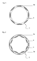
- FIG. 1 shows a cross section of a plastic pipe (1) which has extruded belt-like layers (3a) only on the outside of the pipe.
- the band-like layers (3a) do not protrude beyond the base tube (2).
- the cross section of the plastic tube (1) is approximately circular.
- the band-like layers (3a) are arranged regularly over the circumference of the sewage pipe (1).
- wide regions of the extruded layers (3a) alternate with regions of the base tube (2). This results in using different colors of the base tube (2) and the belt-like layers (3a) in the longitudinal direction of the tube (1) extending striped surface. This makes it easy to distinguish a plastic pipe (1) according to the invention from others if no cover layer (4) is applied to the outside of the pipe (1).
- the base pipe (2) consists of polypropylene, which is provided with barium sulfate as a filler.
- the material used for the production of the plastic tube (1) by coextrusion for the band-like layers (3a) consists of unfilled polypropylene.
- a foaming agent By adding a foaming agent, a foam structure can be created after leaving the mold.
- the surface of the foam structure can be protected by a cover layer (4) against abrasion and contamination.
- a plastic pipe (1) is shown in cross-section, which has an extruded strip-like layer 3 arranged on the pipe inside and on the outside of the pipe on the base pipe (2) and an outer cover layer (4).
- the extruded layers (3a, 3b) and the covering layer (4) consist of a thermoplastic elastomer, the density of the material differing from the base pipe material.
- the band-like layers (3a) arranged on the outside of the pipe form a unit with the covering layer (4) which is particularly resistant to abrasion. Due to the existing thermoplastic elastomer surface (4) also a good handling of the plastic pipe (1) is ensured, which is particularly advantageous during transport and installation of the pipes (1) in a sewer system.
- the extruded ribbon-like layers (3a, 3b) are arranged regularly over the circumference of the plastic tube (1) on the inner and outer tube wall. But there are also irregular arrangements both on the tube inside and on the tube outside of the extruded layers (3a, 3b) possible.
- the regions of the band-like layers (3a, 3b) which are extruded on the inside and outside of the tube in this exemplary embodiment overlap. This ensures that it is ensured over the entire circumference of the sewage pipe (1) that at least one transition between two material compositions with different density is arranged in the radial direction.
- the strip-like layers (3b) which come into contact with the waste water are raised in relation to the base tube (2), whereby a further sound attenuation and thus a reduction of the audible flow noise is achieved. It has also been recognized that a spiral-shaped arrangement of the layers (3b) extruded on the tube inside of the base tube (2) has a particularly favorable effect on the flow behavior of the waste waters and contributes to a reduction in noise. It is possible to carry out the extruded layers (3a, 3b) in a different color scheme than the base tube (2). So that this coloring is still visible as a design element after application of the cover layer (4), the cover layer (4) must be made of a transparent or semitransparent material composition. Thus, it is possible to make the plastic pipe (1) so that it fits into the room design in a laying without subsequent cladding color.
Landscapes
- Engineering & Computer Science (AREA)
- General Engineering & Computer Science (AREA)
- Mechanical Engineering (AREA)
- Rigid Pipes And Flexible Pipes (AREA)
- Extrusion Moulding Of Plastics Or The Like (AREA)
- Feeding, Discharge, Calcimining, Fusing, And Gas-Generation Devices (AREA)
- Processing And Handling Of Plastics And Other Materials For Molding In General (AREA)
- Application Of Or Painting With Fluid Materials (AREA)
- Pipeline Systems (AREA)
- Cleaning In General (AREA)
Abstract
Description
- Die Erfindung betrifft ein Kunststoffrohr und ein Rohrleitungssystem zum Durchleiten von Abwässern.
- Derartige Kunststoffrohre sind auf dem Markt bekannt. Durch das Hindurchleiten der Abwässer durch ein Rohrleitungssystem entsteht Luft- und Körperschall. Dieser breitet sich allseitig aus. Neben der Schallausbreitung im Rohrleitungssystem wird auch Schall durch die Rohrwand an die Umgebung abgestrahlt. Dieser Luftschall wird von Menschen als störendes Geräusch wahrgenommen.
In der Medizin ist bekannt, dass störende Geräusche einen negativen Einfluss auf das Wohlbefinden eines Menschen haben. Aus diesem Grund wird versucht, die Schallabstrahlung von Abwasserrohren zu minimieren. - Durch die Kraftanregung der Rohrwand durch die Abwässer entsteht, bevorzugt an Umlenkungen wie z. B. an Bögen, Krümmern und Abzweigen, Körperschall. Um diesen zu verringern, ist die Einleitung von Kraftsprüngen oder Kraftspitzen zu vermeiden. Da aber die Abwässer nur stoßweise in die Abwasserleitung abgegeben werden, ist dies nur in begrenztem Maße möglich. Aus diesem Grund ist die Schallabstrahlung des Abwasserrohrsystems durch andere Maßnahmen zu verringern.
- Dazu wird durch Schallreflexion des sich ausbreitenden Schalls an einzelnen Unstetigkeiten versucht, die Schallausbreitung von Luft- oder Körperschall zu behindern. Der Schallreflexionsfaktor r ist gegeben durch:

- Dabei nimmt mit größerem Reflexionsfaktor r die schalldämmende Wirkung zu. Dies wird in der Praxis durch einen möglichst großen Impedanzsprung an der reflektierenden Grenzfläche erreicht.
- Unter der Impedanz werden alle Widerstände zusammengefasst, die der Ausbreitung von Schwingungen in einem bestimmten Umfeld entgegenwirken, z. B. haben die Eigenschaften des Ausbreitungsmediums, Hindernisse, Übergänge zu anderen Ausbreitungsmedien, sowie Gegenstände, Flächen bzw. Bereiche mit bestimmten akustischen Eigenschaften Einfluss auf die Impedanz eines Rohrleitungssystems.
- Die Schallkennimpedanz ZF in N·s/m3, auch akustische Feldimpedanz genannt, berechnet sich zu:

p - Schalldruck in N/m2
v - Schallschnelle in m/s
ρ - Dichte in kg/m3
c - Schallgeschwindigkeit in m/s - Daraus ist zu erkennen, dass durch eine Erhöhung der Masse des Rohres eine größere Schallkennimpedanz erreicht werden kann, wodurch wiederum der Sprung zwischen der Impedanz der Abwässer und der des Rohrsystems vergrößert wird.
- Diese Umsetzung wird z. B. in der
EP 254375 B2 - Diese Ausführung hat jedoch den Nachteil, dass die Masse des Rohrsystems mit der Zunahme der Dichte ansteigt, wodurch die Handhabung beim Verbau in Gebäuden erschwert ist.
- Bei dem erfindungsgemäßen Kunststoffrohr wird die Geräuschminderung dadurch erreicht, dass das Kunststoffrohr aus einem Grundrohr mit an der Innen- und/oder Außenfläche des Grundrohres angeordneten einextrudierten bandartigen Schichten besteht, wobei die einextrudierten bandartigen Schichten beabstandet voneinander angeordnet sind und sich die Dichte des Grundrohrmaterials von der Dichte des Materials der einextrudierten bandartigen Schichten unterscheidet.
- Auf diese Weise entsteht ein Kunststoffrohr, das neben dem Dichtesprung zwischen den Abwässern und der Kunststoffrohrwandung mindestens einen weiteren Dichtesprung in radialer Richtung aufweist, an dem die Schallwellen wiederum reflektiert werden und so eine Geräuschminderung eintritt.
- Es hat sich gezeigt, dass es besonders günstig ist, wenn die bandartigen einextrudierten Schichten die gleiche Breite/Ausdehnung aufweisen und regelmäßig über den Umfang des Kunststoffrohres angeordnet sind. Damit entsteht ein symmetrisches mit bandartigen Strukturen versehenes polymeres Rohr, das ohne Berücksichtigung der Einbaulage in ein Abwasserleitungsnetz eingebunden werden kann.
- In diesem Zusammenhang hat es sich auch als vorteilhaft erwiesen, wenn sich die Bereiche der einextrudierten Schichten, die an der Innen- und Außenfläche des Grundrohres angeordnet sind, zumindest teilweise in radialer Richtung überlappen. Dadurch werden zumindest in Teilbereichen des Kunststoffrohres zwei Dichtesprünge geschaffen, die eine Schallreflexion bewirken.
- Die Überlappungsbereiche, der an der Innen- und Außenfläche des Grundrohres angeordneten einextrudierten bandartigen Schichten, liegen vorteilhaft zwischen 5 und 100 Prozent des von den bandartigen Schichten gebildeten Kunststoffrohrumfangs.
- Das Grundrohr und/oder die einextrudierten Schichten können auch farbig oder mehrfarbig ausgeführt werden. Damit ist es möglich, auch sichtbar verlegte Abflussrohre optisch ansprechend, kundenwunschgerecht und an Verlegevorschriften angepasst zu gestalten.
- Es hat sich als vorteilhaft erweisen, die einextrudierten Schichten gegenüber dem Grundrohr erhaben auszubilden. Dabei beträgt der Überstand der Schichten gegenüber dem Grundrohr vorteilhaft 0,2 bis 1,0 mm. Besonders an der Innenfläche des Grundrohres angeordnete erhabene Schichten wirken sich positiv auf das Fließverhalten der Abwässer aus, so dass durch dissipative Prozesse der Abwässer die Schallintensität verringert wird.
- Die durch den Überstand der einextrudierten Schichten entstehende Abweichung des Querschnitts von einem Kreis kann durch das Aufbringen einer Deckschicht auf die innere oder äußere Rohroberfläche ausgeglichen werden.
- Dabei ist die Deckschicht auf der Außenseite des Rohres vorteilhafterweise aus einem transparenten Kunststoff gefertigt, so dass das Grundrohr und die einextrudierten bandartigen Schichten sichtbar sind.
- Bei dem erfindungsgemäßen Kunststoffrohr werden das Grundrohr und/oder die einextrudierten Schichten und/oder die Deckschicht aus einem vernetzten oder unvernetzten thermoplastischen Material hergestellt. Vorteilhaft werden als Werkstoffe für das Kunststoffrohr Polyolefine oder thermoplastische Elastomere eingesetzt. Es hat sich in diesem Erfindungszusammenhang gezeigt, dass es günstig ist, wenn den polymeren Werkstoffen organische und/oder anorganische Füllstoffe zugegeben sind. Bevorzuge werden als Füllstoffe Metallspäne, Wollastonit, Holzmehl, Calciumcarbonat oder Bariumsulfat verwendet.
- Es liegt auch im Rahmen der Erfindung, dass die einextrudierten bandartigen Schichten und/oder das Grundrohr aus einem geschäumten thermoplastischen Kunststoff bestehen und somit auch die bandartigen Schichten eine geringere Dichte als das Grundrohr aufweisen können oder umgekehrt. Das Einbringen einer Schaumstruktur hat den Vorteil, dass die geschäumten Bereiche, sowohl des Grundrohres als auch der einextrudierten Schichten, sich bei Krafteinleitung durch die Abwässer deformieren können und somit die Energie bei der Verformung durch innere Reibung in Wärme umgewandelt wird. Damit verringert sich die durch die Abwässer eingeleitete Energie, so dass auch eine Reduzierung des entstehenden Schalls bewirkt wird.
- Für die Herstellung der Schaumstruktur können gasabspaltende chemische Verbindungen als Treibmittel eingesetzt werden. Als organische Treibmittel werden Azodicarbonamid, Benzolsulfohydrazid, Cyanursäuretrihydrazid und/oder Diphenylenoxid-4,4'-disulfohydrazid und als anorganische Treibmittel wird insbesondere Natriumhydrogencarbonat verwendet. Als Hilfsmittel zur Schaumbildung werden Magnesiumoxid und Zinkoxid eingesetzt. Es werden aber auch Mischungen der polymeren Kunststoffe mit Gasen, wie z. B. Pentan, Isopentan, Propan, Isobutan, Monofluortrichlormethan, Difluordichlormethan, Stickstoff, Argon und/oder Kohlendioxid hergestellt. Nach dem Formbildungsschritt in einem Extrusionswerkzeug entspannen sich die eingemischten Gase, wodurch eine Schaumstruktur entlang der Rohroberfläche gebildet wird.
- Um die Kunststoffrohre in ein Abwasserleitungssystem einzubinden, wird an einem Rohrende eine Rohrmuffe angebracht, so dass die Kunststoffrohre miteinander oder mit Kunststoffrohrformteilen, wie Abzweige, Bögen oder dergleichen, verbunden werden können.
- Durch die Einbindung erfindungsgemäßer Kunststoffrohre in ein Rohrleitungssystem ist es möglich, die hörbaren Geräusche, die durch das Hindurchleiten der Abwässer entlang der Verlegestücke entstehen, vorteilhaft zu reduzieren.
- Die Erfindung soll nun an nicht einschränkenden Ausführungsbeispielen näher beschrieben werden. Es zeigt:
- Figur 1 - Querschnitt eines Kunststoffrohres ohne Deckschicht
- Figur 2 - Querschnitt eines Kunststoffrohrs mit äußerer Deckschicht
- In Figur 1 ist ein Kunststoffrohr (1) im Querschnitt dargestellt, das nur an der Rohraußenseite einextrudierte bandartige Schichten (3a) aufweist. In diesem Ausführungsbeispiel stehen die bandartigen Schichten (3a) nicht über das Grundrohr (2) hinaus. Damit ist der Querschnitt des Kunststoffrohres (1) annähernd kreisförmig.
Die bandartigen Schichten (3a) sind regelmäßig über den Umfang des Abwasserrohres (1) angeordnet. An der Oberfläche wechseln sich breite Bereiche der einextrudierten Schichten (3a) mit Bereichen des Grundrohres (2) ab. Dadurch entsteht bei Verwendung unterschiedlicher Farbgebungen des Grundrohres (2) und der bandartigen Schichten (3a) eine in Längsrichtung des Rohres (1) verlaufende gestreifte Oberfläche. Damit ist ein erfindungsgemäßes Kunststoffrohr (1) von anderen leicht zu unterscheiden, wenn keine Deckschicht (4) an der Außenseite des Rohres (1) aufgebracht ist.
In diesem Beispiel besteht das Grundrohr (2) aus Polypropylen, das mit Bariumsulfat als Füllstoff versehen ist. Das bei der Herstellung des Kunststoffrohres (1) durch Koextrusion verwendete Material für die bandartigen Schichten (3a) besteht aus ungefülltem Polypropylen. Durch die Zugabe eines Schaumbildners kann nach dem Verlassen des Werkzeugs eine Schaumstruktur erzeugt werden. Die Oberfläche der Schaumstruktur kann durch eine Deckschicht (4) gegen Abrieb und Verschmutzung geschützt werden. Es ist aber auch möglich eine geschlossenporige bandartige Schaumschicht (3a) herzustellen, die keinen separaten Schutz benötigt. - In Figur 2 ist ein Kunststoffrohr (1) im Querschnitt dargestellt, das an der Rohrinnenseite und an der Rohraußenseite an dem Grundrohr (2) angeordnete einextrudierte bandartige Schichten 3 sowie eine äußere Deckschicht (4) aufweist. Bei dem erfindungsgemäßen Abwasserrohr (1) bestehen die einextrudierten Schichten (3a, 3b) und die Deckschicht (4) aus einem thermoplastischen Elastomer, wobei sich die Dichte das Material gegenüber dem Grundrohrmaterial unterscheidet. Die auf der Rohraußenseite angeordneten bandartigen Schichten (3a) bilden mit der Deckschicht (4) eine Einheit, die besonders abriebfest ist. Durch die aus thermoplastischem Elastomer bestehende Oberfläche (4) wird außerdem eine gute Handhabbarkeit der Kunststoffrohres (1) gewährleistet, was besonders beim Transport und beim Einbau der Rohre (1) in ein Abwasserleitungssystem vorteilhaft ist.
In diesem Beispiel sind die einextrudierten bandartigen Schichten (3a, 3b) regelmäßig über den Umfang des Kunststoffrohres (1) an der inneren und äußeren Rohrwand angeordnet. Es sind aber auch unregelmäßige Anordnungen sowohl an der Rohrinnen- als auch an der Rohraußenseite der einextrudierten Schichten (3a, 3b) möglich.
In radialer Richtung überlappen sich die Bereiche der bandartigen Schichten (3a, 3b), die an der Rohrinnen- und Rohraußenseite in diesem Ausführungsbeispiel einextrudiert sind. Damit wird erreicht, dass über den gesamten Umfang des Abwasserrohres (1) gewährleistet ist, dass in radialer Richtung mindestens ein Übergang zwischen zwei Materialzusammensetzungen mit unterschiedlicher Dichte angeordnet ist.
Die mit dem Abwasser in Berührung kommenden bandartigen Schichten (3b) sind gegenüber dem Grundrohr (2) erhaben ausgebildet, wodurch eine weitere Schalldämpfung und somit eine Minderung der hörbaren Fließgeräusche erreicht wird.
Es wurde auch erkannt, dass eine spiralförmige Anordnung der an der Rohrinnenseite des Grundrohres (2) einextrudierten Schichten (3b) sich besonders günstig auf das Fließverhalten der Abwässer auswirkt und zu einer Schallreduzierung beiträgt.
Es ist möglich, die einextrudierten Schichten (3a, 3b) in einer anderen Farbgestaltung als das Grundrohr (2) auszuführen. Damit diese Farbgebung auch als gestalterisches Element nach dem Aufbringen der Deckschicht (4) noch sichtbar ist, muss die Deckschicht (4) aus einer transparenten oder semitransparenten Materialzusammensetzung gefertigt sein. Somit ist es möglich, das Kunststoffrohr (1) so zu gestalten, dass es bei einer Verlegung ohne nachträgliche Verkleidung sich farblich in die Raumgestaltung einfügt.
Claims (15)
- Kunststoffrohr (1) zum Durchleiten von Abwässern, dadurch gekennzeichnet, dass das Kunststoffrohr (1) aus einem Grundrohr (2) mit an der Innen- und/oder Außenfläche des Grundrohres (2) angeordneten einextrudierten bandartigen Schichten (3a, 3b), die beabstandet voneinander angeordnet sind, besteht, und dass sich die Dichte des Grundrohrmaterials von der Dichte des Materials der einextrudierten bandartigen Schichten (3a, 3b) unterscheidet.
- Kunststoffrohr (1) nach Anspruch 1, dadurch gekennzeichnet, dass die einextrudierten bandartigen Schichten (3a, 3b) an der Innen- und/oder an der Außenfläche des Grundrohres (2) die gleiche Bandbreite aufweisen und regelmäßig über den Umfang des Kunststoffrohres (1) angeordnet sind.
- Kunststoffrohr (1) nach Anspruch 1 oder 2, dadurch gekennzeichnet, dass die Bereiche der einextrudierten Schichten (3a, 3b) an der Innen- und an der Außenfläche des Grundrohres (2) sich in radialer Richtung zumindest teilweise überlappen.
- Kunststoffrohr (1) nach Anspruch 3, dadurch gekennzeichnet, dass die an der Innen- und an der Außenfläche des Grundrohres (2) angeordneten einextrudierten Schichten (3a, 3b) im Bereich von 5 bis 100 Prozent überlappen.
- Kunststoffrohr (1) nach zumindest einem der vorherigen Ansprüche, dadurch gekennzeichnet, dass das Grundrohr (2) und/oder die einextrudierten Schichten (3a, 3b) farbig oder mehrfarbig ausgeführt sind.
- Kunststoffrohr (1) nach zumindest einem der vorherigen Ansprüche, dadurch gekennzeichnet, dass die an der Innen- und/oder Außenfläche des Grundrohres (2) angeordneten einextrudierten Schichten (3a, 3b) gegenüber dem Grundrohr (2) erhaben ausgebildet sind.
- Kunststoffrohr (1) nach Anspruch 6, dadurch gekennzeichnet, dass die einextrudierten Schichten (3a, 3b) zwischen 0,2 und 1,0 mm gegenüber dem Grundrohr (2) überstehen.
- Kunststoffrohr (1) nach zumindest einem der vorherigen Ansprüche, dadurch gekennzeichnet, dass das Kunststoffrohr (1) innen und/oder außen eine Deckschicht (4) über dem Grundrohr (2) und den einextrudierten Schichten (3a, 3b) aufweist.
- Kunststoffrohr (1) nach Anspruch 6, dadurch gekennzeichnet, dass die äußere Deckschicht (4) transparent ist.
- Kunststoffrohr (1) nach zumindest einem der vorhergehenden Ansprüche, dadurch gekennzeichnet, dass das Grundrohr (2) und/oder die einextrudierten Schichten (3a, 3b) und/oder die Deckschicht (4) aus einem vernetzten oder unvernetzten thermoplastischen Material, insbesondere aus einem Polyolefin oder einem thermoplastischen Elastomer, bestehen.
- Kunststoffrohr (1) nach Anspruch 10, dadurch gekennzeichnet, dass das Material organische und/oder anorganische Füllstoffe enthält.
- Kunststoffrohr (1) nach zumindest einem der vorhergehenden Ansprüche, dadurch gekennzeichnet, dass das Kunststoffrohr (1) zumindest abschnittsweise geschäumte Bereiche aufweist.
- Kunststoffrohr (1) nach zumindest einem der vorhergehenden Ansprüche, dadurch gekennzeichnet, dass das Kunststoffrohr (1) durch Koextrusion hergestellt ist.
- Rohrleitungssystem zum Durchleiten von Abwässern, wobei das Rohrleitungssystem mindestens ein Kunststoffrohr (1) gemäß Anspruch 1 enthält.
- Rohrleitungssystem nach Anspruch 14, dadurch gekennzeichnet, dass durch das Rohrleitungssystem die hörbaren Geräusche vermindert sind.
Priority Applications (1)
| Application Number | Priority Date | Filing Date | Title |
|---|---|---|---|
| PL07006761T PL1850046T3 (pl) | 2006-04-28 | 2007-03-31 | Rura z tworzywa sztucznego i układ rurociągów do prowadzenia ścieków |
Applications Claiming Priority (1)
| Application Number | Priority Date | Filing Date | Title |
|---|---|---|---|
| DE102006020375A DE102006020375A1 (de) | 2006-04-28 | 2006-04-28 | Kunststoffrohr und Rohrleitungssystem zum Durchleiten von Abwässern |
Publications (2)
| Publication Number | Publication Date |
|---|---|
| EP1850046A1 true EP1850046A1 (de) | 2007-10-31 |
| EP1850046B1 EP1850046B1 (de) | 2009-03-11 |
Family
ID=38319554
Family Applications (1)
| Application Number | Title | Priority Date | Filing Date |
|---|---|---|---|
| EP07006761A Not-in-force EP1850046B1 (de) | 2006-04-28 | 2007-03-31 | Kunststoffrohr und Rohrleitungssystem zum Durchleiten von Abwässern |
Country Status (4)
| Country | Link |
|---|---|
| EP (1) | EP1850046B1 (de) |
| AT (1) | ATE425399T1 (de) |
| DE (2) | DE102006020375A1 (de) |
| PL (1) | PL1850046T3 (de) |
Cited By (2)
| Publication number | Priority date | Publication date | Assignee | Title |
|---|---|---|---|---|
| FR2963653A1 (fr) * | 2010-08-03 | 2012-02-10 | Hozelock Tricoflex | Tuyau d'arrosage a face externe adherente et glissante |
| CN106015771A (zh) * | 2016-07-18 | 2016-10-12 | 江苏宝鹏科技管业有限公司 | 高耐候耐磨型pe给水管 |
Families Citing this family (5)
| Publication number | Priority date | Publication date | Assignee | Title |
|---|---|---|---|---|
| DE102013111961A1 (de) | 2013-10-30 | 2015-04-30 | Egeplast International Gmbh | Kunststoffrohr |
| DE102016125325A1 (de) | 2016-12-22 | 2018-06-28 | Rehau Ag + Co | Verfahren zur Herstellung einer Rohrverbindung sowie Rohr zur Verwendung in einem derartigen Verfahren |
| DE102017105807B3 (de) | 2017-03-17 | 2018-08-16 | Schlemmer Holding GmbH | Mehrkomponenten-Extrusionsspritzkopf, Mehrkomponenten-Extrusionsanlage und Verfahren zum Herstellen eines Verbundschlauchs |
| DE102018131750A1 (de) | 2018-12-11 | 2020-06-18 | Rehau Ag + Co | Rohrverbindung, Verfahren zur ihrer Herstellung sowie Rohr |
| DE202018107107U1 (de) | 2018-12-12 | 2020-03-13 | Rehau Ag + Co | Rohrverbindungsanordnung |
Citations (3)
| Publication number | Priority date | Publication date | Assignee | Title |
|---|---|---|---|---|
| US3524476A (en) * | 1967-09-28 | 1970-08-18 | Us Navy | Pipe wall shear damping treatment |
| EP0254375A1 (de) * | 1986-07-23 | 1988-01-27 | Wavin B.V. | Aus thermoplastischem Kunststoff hergestelltes Kunststoffrohrteil mit schalldämpfenden Eigenschaften und Abfahrröhrensystem, welches solche Kunststoffrohrteile enthält |
| US5795634A (en) * | 1995-09-22 | 1998-08-18 | Totaku Industries, Inc. | Heat insulating noise reducing duct |
Family Cites Families (2)
| Publication number | Priority date | Publication date | Assignee | Title |
|---|---|---|---|---|
| GB1517344A (en) * | 1975-06-05 | 1978-07-12 | Lagercrantz B | Tubing |
| FI100130B (fi) * | 1995-12-12 | 1997-09-30 | Uponor Innovation Ab | Monikerroksinen muoviputki |
-
2006
- 2006-04-28 DE DE102006020375A patent/DE102006020375A1/de not_active Withdrawn
-
2007
- 2007-03-31 DE DE502007000492T patent/DE502007000492D1/de active Active
- 2007-03-31 PL PL07006761T patent/PL1850046T3/pl unknown
- 2007-03-31 EP EP07006761A patent/EP1850046B1/de not_active Not-in-force
- 2007-03-31 AT AT07006761T patent/ATE425399T1/de active
Patent Citations (3)
| Publication number | Priority date | Publication date | Assignee | Title |
|---|---|---|---|---|
| US3524476A (en) * | 1967-09-28 | 1970-08-18 | Us Navy | Pipe wall shear damping treatment |
| EP0254375A1 (de) * | 1986-07-23 | 1988-01-27 | Wavin B.V. | Aus thermoplastischem Kunststoff hergestelltes Kunststoffrohrteil mit schalldämpfenden Eigenschaften und Abfahrröhrensystem, welches solche Kunststoffrohrteile enthält |
| US5795634A (en) * | 1995-09-22 | 1998-08-18 | Totaku Industries, Inc. | Heat insulating noise reducing duct |
Cited By (2)
| Publication number | Priority date | Publication date | Assignee | Title |
|---|---|---|---|---|
| FR2963653A1 (fr) * | 2010-08-03 | 2012-02-10 | Hozelock Tricoflex | Tuyau d'arrosage a face externe adherente et glissante |
| CN106015771A (zh) * | 2016-07-18 | 2016-10-12 | 江苏宝鹏科技管业有限公司 | 高耐候耐磨型pe给水管 |
Also Published As
| Publication number | Publication date |
|---|---|
| DE102006020375A1 (de) | 2007-11-15 |
| ATE425399T1 (de) | 2009-03-15 |
| PL1850046T3 (pl) | 2009-08-31 |
| EP1850046B1 (de) | 2009-03-11 |
| DE502007000492D1 (de) | 2009-04-23 |
Similar Documents
| Publication | Publication Date | Title |
|---|---|---|
| EP1850046B1 (de) | Kunststoffrohr und Rohrleitungssystem zum Durchleiten von Abwässern | |
| DE69229234T2 (de) | Schichtstoff | |
| DE69631432T2 (de) | Koextrudierte mehrschichtige kunststoffrohre | |
| DE3220023A1 (de) | Schallgedaempfter stroemungskanal und verfahren zu seiner herstellung | |
| DE2714576C2 (de) | Kunststoffrohrteil für Abflußrohrsysteme | |
| DE4143646C2 (de) | Schalldämmmaterial für Rohrleitungen | |
| DE8718020U1 (de) | Kunststoffrohrteil | |
| AT391008B (de) | Kunststoffrohr bzw. rohrformstueck | |
| DE3536379A1 (de) | Luftfuehrungskanal, insbesondere in kraftfahrzeugen | |
| DE3439312C2 (de) | Doppellagiger flexibler Kunststoffschlauch, insbesondere als Leitung für fluorierte Kohlenwasserstoffe | |
| DE4429045B4 (de) | Dämmmaterial | |
| EP1754919B1 (de) | Rohr mit doppelter Sperrschicht | |
| DE3307120A1 (de) | Fernwaermeleitungsrohr | |
| DE69806305T2 (de) | Schalldämmendes Rohrprofil und durch ein solches Profil gebildete Dichtung, für das Einfassen einer Kraftfahrzeugöffnung | |
| CH718489B1 (de) | Thermisch gedämmtes Rohr. | |
| WO2007137720A1 (de) | Formteil für leitungssysteme zum durchleiten von abwässern | |
| EP1584460A1 (de) | Kunststoffrohr bzw. Rohrformstück | |
| DE2556224A1 (de) | Schutzelement zur schalldaemmung | |
| CH676576A5 (de) | ||
| EP0829674A1 (de) | Körperschalldämmende Beschichtung von Abwasserrohren und -formstücken aus Kunststoff | |
| DE19541414C1 (de) | Rohr oder Rohrteil aus thermoplastischem Werkstoff | |
| DE2204132C3 (de) | Verfahren zum Herstellen eines I nstallationsblockes | |
| DE4431002C2 (de) | Schalldämmendes Formstück aus Kunststoff | |
| DE10112701A1 (de) | Schallgedämmte Dose für Unterputzinstallationen sowie schallgedämmte Installationseinheit | |
| AT8765U1 (de) | Schallgedämpftes kunststoffrohrteil |
Legal Events
| Date | Code | Title | Description |
|---|---|---|---|
| PUAI | Public reference made under article 153(3) epc to a published international application that has entered the european phase |
Free format text: ORIGINAL CODE: 0009012 |
|
| AK | Designated contracting states |
Kind code of ref document: A1 Designated state(s): AT BE BG CH CY CZ DE DK EE ES FI FR GB GR HU IE IS IT LI LT LU LV MC MT NL PL PT RO SE SI SK TR |
|
| AX | Request for extension of the european patent |
Extension state: AL BA HR MK YU |
|
| 17P | Request for examination filed |
Effective date: 20080125 |
|
| AKX | Designation fees paid |
Designated state(s): AT BE BG CH CY CZ DE DK EE ES FI FR GB GR HU IE IS IT LI LT LU LV MC MT NL PL PT RO SE SI SK TR |
|
| GRAP | Despatch of communication of intention to grant a patent |
Free format text: ORIGINAL CODE: EPIDOSNIGR1 |
|
| GRAS | Grant fee paid |
Free format text: ORIGINAL CODE: EPIDOSNIGR3 |
|
| GRAA | (expected) grant |
Free format text: ORIGINAL CODE: 0009210 |
|
| AK | Designated contracting states |
Kind code of ref document: B1 Designated state(s): AT BE BG CH CY CZ DE DK EE ES FI FR GB GR HU IE IS IT LI LT LU LV MC MT NL PL PT RO SE SI SK TR |
|
| REG | Reference to a national code |
Ref country code: GB Ref legal event code: FG4D Free format text: NOT ENGLISH |
|
| REG | Reference to a national code |
Ref country code: CH Ref legal event code: EP |
|
| REG | Reference to a national code |
Ref country code: IE Ref legal event code: FG4D Free format text: LANGUAGE OF EP DOCUMENT: GERMAN |
|
| REF | Corresponds to: |
Ref document number: 502007000492 Country of ref document: DE Date of ref document: 20090423 Kind code of ref document: P |
|
| PG25 | Lapsed in a contracting state [announced via postgrant information from national office to epo] |
Ref country code: LT Free format text: LAPSE BECAUSE OF FAILURE TO SUBMIT A TRANSLATION OF THE DESCRIPTION OR TO PAY THE FEE WITHIN THE PRESCRIBED TIME-LIMIT Effective date: 20090311 Ref country code: FI Free format text: LAPSE BECAUSE OF FAILURE TO SUBMIT A TRANSLATION OF THE DESCRIPTION OR TO PAY THE FEE WITHIN THE PRESCRIBED TIME-LIMIT Effective date: 20090311 Ref country code: SI Free format text: LAPSE BECAUSE OF FAILURE TO SUBMIT A TRANSLATION OF THE DESCRIPTION OR TO PAY THE FEE WITHIN THE PRESCRIBED TIME-LIMIT Effective date: 20090311 |
|
| 26 | Opposition filed |
Opponent name: SABIC INNOVATIVE PLASTICS B.V. Effective date: 20090707 |
|
| PG25 | Lapsed in a contracting state [announced via postgrant information from national office to epo] |
Ref country code: LV Free format text: LAPSE BECAUSE OF FAILURE TO SUBMIT A TRANSLATION OF THE DESCRIPTION OR TO PAY THE FEE WITHIN THE PRESCRIBED TIME-LIMIT Effective date: 20090311 Ref country code: SE Free format text: LAPSE BECAUSE OF FAILURE TO SUBMIT A TRANSLATION OF THE DESCRIPTION OR TO PAY THE FEE WITHIN THE PRESCRIBED TIME-LIMIT Effective date: 20090611 |
|
| REG | Reference to a national code |
Ref country code: PL Ref legal event code: T3 |
|
| BERE | Be: lapsed |
Owner name: REHAU A.G. + CO Effective date: 20090331 |
|
| NLR1 | Nl: opposition has been filed with the epo |
Opponent name: SABIC INNOVATIVE PLASTICS B.V. |
|
| REG | Reference to a national code |
Ref country code: IE Ref legal event code: FD4D |
|
| PG25 | Lapsed in a contracting state [announced via postgrant information from national office to epo] |
Ref country code: PT Free format text: LAPSE BECAUSE OF FAILURE TO SUBMIT A TRANSLATION OF THE DESCRIPTION OR TO PAY THE FEE WITHIN THE PRESCRIBED TIME-LIMIT Effective date: 20090824 Ref country code: ES Free format text: LAPSE BECAUSE OF FAILURE TO SUBMIT A TRANSLATION OF THE DESCRIPTION OR TO PAY THE FEE WITHIN THE PRESCRIBED TIME-LIMIT Effective date: 20090622 Ref country code: CZ Free format text: LAPSE BECAUSE OF FAILURE TO SUBMIT A TRANSLATION OF THE DESCRIPTION OR TO PAY THE FEE WITHIN THE PRESCRIBED TIME-LIMIT Effective date: 20090311 Ref country code: EE Free format text: LAPSE BECAUSE OF FAILURE TO SUBMIT A TRANSLATION OF THE DESCRIPTION OR TO PAY THE FEE WITHIN THE PRESCRIBED TIME-LIMIT Effective date: 20090311 Ref country code: MC Free format text: LAPSE BECAUSE OF NON-PAYMENT OF DUE FEES Effective date: 20090331 Ref country code: IE Free format text: LAPSE BECAUSE OF FAILURE TO SUBMIT A TRANSLATION OF THE DESCRIPTION OR TO PAY THE FEE WITHIN THE PRESCRIBED TIME-LIMIT Effective date: 20090311 |
|
| PG25 | Lapsed in a contracting state [announced via postgrant information from national office to epo] |
Ref country code: IS Free format text: LAPSE BECAUSE OF FAILURE TO SUBMIT A TRANSLATION OF THE DESCRIPTION OR TO PAY THE FEE WITHIN THE PRESCRIBED TIME-LIMIT Effective date: 20090711 Ref country code: RO Free format text: LAPSE BECAUSE OF FAILURE TO SUBMIT A TRANSLATION OF THE DESCRIPTION OR TO PAY THE FEE WITHIN THE PRESCRIBED TIME-LIMIT Effective date: 20090311 Ref country code: SK Free format text: LAPSE BECAUSE OF FAILURE TO SUBMIT A TRANSLATION OF THE DESCRIPTION OR TO PAY THE FEE WITHIN THE PRESCRIBED TIME-LIMIT Effective date: 20090311 |
|
| PLBE | No opposition filed within time limit |
Free format text: ORIGINAL CODE: 0009261 |
|
| STAA | Information on the status of an ep patent application or granted ep patent |
Free format text: STATUS: NO OPPOSITION FILED WITHIN TIME LIMIT |
|
| PG25 | Lapsed in a contracting state [announced via postgrant information from national office to epo] |
Ref country code: BG Free format text: LAPSE BECAUSE OF FAILURE TO SUBMIT A TRANSLATION OF THE DESCRIPTION OR TO PAY THE FEE WITHIN THE PRESCRIBED TIME-LIMIT Effective date: 20090611 Ref country code: DK Free format text: LAPSE BECAUSE OF FAILURE TO SUBMIT A TRANSLATION OF THE DESCRIPTION OR TO PAY THE FEE WITHIN THE PRESCRIBED TIME-LIMIT Effective date: 20090311 |
|
| 26N | No opposition filed |
Effective date: 20091214 |
|
| PG25 | Lapsed in a contracting state [announced via postgrant information from national office to epo] |
Ref country code: BE Free format text: LAPSE BECAUSE OF NON-PAYMENT OF DUE FEES Effective date: 20090331 |
|
| PG25 | Lapsed in a contracting state [announced via postgrant information from national office to epo] |
Ref country code: GR Free format text: LAPSE BECAUSE OF FAILURE TO SUBMIT A TRANSLATION OF THE DESCRIPTION OR TO PAY THE FEE WITHIN THE PRESCRIBED TIME-LIMIT Effective date: 20090612 |
|
| PG25 | Lapsed in a contracting state [announced via postgrant information from national office to epo] |
Ref country code: LU Free format text: LAPSE BECAUSE OF NON-PAYMENT OF DUE FEES Effective date: 20090331 Ref country code: MT Free format text: LAPSE BECAUSE OF FAILURE TO SUBMIT A TRANSLATION OF THE DESCRIPTION OR TO PAY THE FEE WITHIN THE PRESCRIBED TIME-LIMIT Effective date: 20090311 |
|
| PGRI | Patent reinstated in contracting state [announced from national office to epo] |
Ref country code: IT Effective date: 20110501 |
|
| PG25 | Lapsed in a contracting state [announced via postgrant information from national office to epo] |
Ref country code: HU Free format text: LAPSE BECAUSE OF FAILURE TO SUBMIT A TRANSLATION OF THE DESCRIPTION OR TO PAY THE FEE WITHIN THE PRESCRIBED TIME-LIMIT Effective date: 20090912 |
|
| PG25 | Lapsed in a contracting state [announced via postgrant information from national office to epo] |
Ref country code: CY Free format text: LAPSE BECAUSE OF FAILURE TO SUBMIT A TRANSLATION OF THE DESCRIPTION OR TO PAY THE FEE WITHIN THE PRESCRIBED TIME-LIMIT Effective date: 20090311 |
|
| REG | Reference to a national code |
Ref country code: CH Ref legal event code: PL |
|
| GBPC | Gb: european patent ceased through non-payment of renewal fee |
Effective date: 20110331 |
|
| PG25 | Lapsed in a contracting state [announced via postgrant information from national office to epo] |
Ref country code: LI Free format text: LAPSE BECAUSE OF NON-PAYMENT OF DUE FEES Effective date: 20110331 Ref country code: CH Free format text: LAPSE BECAUSE OF NON-PAYMENT OF DUE FEES Effective date: 20110331 |
|
| PG25 | Lapsed in a contracting state [announced via postgrant information from national office to epo] |
Ref country code: GB Free format text: LAPSE BECAUSE OF NON-PAYMENT OF DUE FEES Effective date: 20110331 |
|
| REG | Reference to a national code |
Ref country code: FR Ref legal event code: PLFP Year of fee payment: 10 |
|
| REG | Reference to a national code |
Ref country code: FR Ref legal event code: PLFP Year of fee payment: 11 |
|
| REG | Reference to a national code |
Ref country code: CH Ref legal event code: PK Free format text: DER EINTRAG 'EINSPRUCH' ERFOLGTE IRRTUEMLICH |
|
| REG | Reference to a national code |
Ref country code: FR Ref legal event code: PLFP Year of fee payment: 12 |
|
| PGFP | Annual fee paid to national office [announced via postgrant information from national office to epo] |
Ref country code: FR Payment date: 20180201 Year of fee payment: 12 Ref country code: PL Payment date: 20180202 Year of fee payment: 12 Ref country code: IT Payment date: 20180228 Year of fee payment: 12 |
|
| PGFP | Annual fee paid to national office [announced via postgrant information from national office to epo] |
Ref country code: GB Payment date: 20190313 Year of fee payment: 14 |
|
| PG25 | Lapsed in a contracting state [announced via postgrant information from national office to epo] |
Ref country code: IT Free format text: LAPSE BECAUSE OF NON-PAYMENT OF DUE FEES Effective date: 20190331 Ref country code: FR Free format text: LAPSE BECAUSE OF NON-PAYMENT OF DUE FEES Effective date: 20190331 |
|
| PGFP | Annual fee paid to national office [announced via postgrant information from national office to epo] |
Ref country code: NL Payment date: 20200303 Year of fee payment: 14 Ref country code: AT Payment date: 20200303 Year of fee payment: 14 |
|
| REG | Reference to a national code |
Ref country code: NL Ref legal event code: MM Effective date: 20210401 |
|
| REG | Reference to a national code |
Ref country code: AT Ref legal event code: MM01 Ref document number: 425399 Country of ref document: AT Kind code of ref document: T Effective date: 20210331 |
|
| PG25 | Lapsed in a contracting state [announced via postgrant information from national office to epo] |
Ref country code: PL Free format text: LAPSE BECAUSE OF NON-PAYMENT OF DUE FEES Effective date: 20190331 |
|
| PG25 | Lapsed in a contracting state [announced via postgrant information from national office to epo] |
Ref country code: NL Free format text: LAPSE BECAUSE OF NON-PAYMENT OF DUE FEES Effective date: 20210401 Ref country code: AT Free format text: LAPSE BECAUSE OF NON-PAYMENT OF DUE FEES Effective date: 20210331 |
|
| REG | Reference to a national code |
Ref country code: DE Ref legal event code: R081 Ref document number: 502007000492 Country of ref document: DE Owner name: REHAU INDUSTRIES SE & CO. KG, DE Free format text: FORMER OWNER: REHAU AG + CO, 95111 REHAU, DE |
|
| PG25 | Lapsed in a contracting state [announced via postgrant information from national office to epo] |
Ref country code: TR Free format text: LAPSE BECAUSE OF NON-PAYMENT OF DUE FEES Effective date: 20200331 |
|
| PGFP | Annual fee paid to national office [announced via postgrant information from national office to epo] |
Ref country code: DE Payment date: 20230331 Year of fee payment: 17 |
|
| REG | Reference to a national code |
Ref country code: DE Ref legal event code: R119 Ref document number: 502007000492 Country of ref document: DE |
|
| PG25 | Lapsed in a contracting state [announced via postgrant information from national office to epo] |
Ref country code: DE Free format text: LAPSE BECAUSE OF NON-PAYMENT OF DUE FEES Effective date: 20241001 |
|
| PG25 | Lapsed in a contracting state [announced via postgrant information from national office to epo] |
Ref country code: DE Free format text: LAPSE BECAUSE OF NON-PAYMENT OF DUE FEES Effective date: 20241001 |