EP1849927B1 - Schalungselement - Google Patents
Schalungselement Download PDFInfo
- Publication number
- EP1849927B1 EP1849927B1 EP06024261A EP06024261A EP1849927B1 EP 1849927 B1 EP1849927 B1 EP 1849927B1 EP 06024261 A EP06024261 A EP 06024261A EP 06024261 A EP06024261 A EP 06024261A EP 1849927 B1 EP1849927 B1 EP 1849927B1
- Authority
- EP
- European Patent Office
- Prior art keywords
- element according
- formwork element
- holding
- wall
- holding elements
- Prior art date
- Legal status (The legal status is an assumption and is not a legal conclusion. Google has not performed a legal analysis and makes no representation as to the accuracy of the status listed.)
- Not-in-force
Links
Images


Classifications
-
- E—FIXED CONSTRUCTIONS
- E04—BUILDING
- E04B—GENERAL BUILDING CONSTRUCTIONS; WALLS, e.g. PARTITIONS; ROOFS; FLOORS; CEILINGS; INSULATION OR OTHER PROTECTION OF BUILDINGS
- E04B2/00—Walls, e.g. partitions, for buildings; Wall construction with regard to insulation; Connections specially adapted to walls
- E04B2/84—Walls made by casting, pouring, or tamping in situ
- E04B2/86—Walls made by casting, pouring, or tamping in situ made in permanent forms
- E04B2/8635—Walls made by casting, pouring, or tamping in situ made in permanent forms with ties attached to the inner faces of the forms
- E04B2/8641—Walls made by casting, pouring, or tamping in situ made in permanent forms with ties attached to the inner faces of the forms using dovetail-type connections
Definitions
- the invention relates to a formwork element, in particular for shell construction, with two wall space enclosing a wall space between them and at least one wall panels enclosing spacers.
- Such a wall element is for example from the DE 196 32 528 A1 known, where the inner surfaces of the wall panels have undercut recesses and also arranged as a plastic injection molded part spacers plate-shaped sections are arranged, which are precisely inserted vertically into the recesses. There are also dovetailed groove cross-sections z B. from the DE 20 2004 015 083 U1 known.
- shuttering elements for shell concrete construction known in which on the inner surfaces of the wall panels regular groove structures are formed, in which parallel webs can be inserted and bonded to terminal plates of a spacer. It is also known to form dovetail-shaped projections on the inner surfaces of the wall panels, via which spacers can be pushed with complementary recesses.
- the WO 03/097957 shows a formwork element in which the inner surface of wall panels have a periodic pattern of vertical wedge-shaped undercut joints and the spacers on outer surfaces of connected via a central part connection plates four complementary to the joints shaped vertical continuous support members side by side.
- the WO 02/055798 A2 describes a clam shell wall element having an outer and an inner wall plate, which have at the one of the facing surfaces undercut grooves into which spacers are inserted with dovetailed ends.
- the spacers are designed as one-piece plastic body with an elongate central part connecting the two dovetail-shaped ends.
- the spacers on the one hand have the function to connect the two wall panels to a uniform in the construction of a wall formwork element, and must hold together for filling the hollow wall space with fresh concrete, the wall panels against the pressure of the filled concrete.
- the present invention has for its object to provide a reliable and cost-effective formwork element of the aforementioned type.
- Breakthroughs through the base plate in areas of projection of the retaining flanks on the base plate are of particular advantage for the production of the preferred embodiments of the base plates as plastic injection molded parts.
- the breakthroughs allow the immersion of Formkemen by the contact surface of the base plate in the direction of the retaining flanks.
- an injection mold is used for the connection plates, which has two in the direction of the surface normal of the plane of the contact surface of the base plate relative to each other deformable mold halves and no further moving parts that determine the shape of the connection plates are required.
- First mandrels on a first mold half of the injection mold with end faces for the retaining flanks and second mandrels on a second mold half for the depressions dive in the opposite direction in the mold space and determine with spaced-apart opposing surfaces of the walls of the holding elements. Further cores on the second mold half dive along the first mold cores to the base plate.
- connection structures on the wall space to and from the holding elements facing away side of the connection plates.
- projections are provided on some or more second cores for the recesses, which cause openings in the base plate at the base of the holding elements on the base plate in extension of the recesses and on the wall space facing side of the base plate with re-immersing cores first mold half define such connection structures.
- the holding elements expand with substantially planar Holding flanks, so that in cross-section, the retaining flanks form a trapezoidal shape with a bearing plane of the base plate to the wall plate.
- the angle of inclination of the flat retaining flanks against the preferably flat contact surface of the base plate is advantageously between 20 and 45, preferably between 25 ° and 35 °.
- connection plate or its base plate to a wall plate is a typically substantially outwardly to the inner surface of the wall plate facing out enveloping surface of the base plate understood without regard to the projecting from this holding structures.
- the recesses Due to the remote from the base plate front side of the holding elements forth recesses introduced into the holding elements, the amount required for the spacers or the base plates plastic compared to an execution platform with massive solid support elements to the front surface, in particular the material savings at the end face in the greatest width of the holding elements can be achieved.
- the recesses are also advantageous injection molding because of the thereby reduceable material thickness.
- the side walls delimiting the depressions and forming the holding flanks side walls of the holding elements can in advantageous embodiments in their course away from the base plate have a constant wall thickness.
- the wall thickness can also vary, in particular continuously taper.
- Such preferably wall-shaped webs can in particular be set at the ends of holding elements and or as intermediate wall webs in the course of such holding elements.
- a plurality of holding elements in a Einschieberaum spaced successively and spaced and / or transversely to the insertion direction, preferably arranged in a plurality of parallel rows, each with a plurality of holding elements. Between in the insertion direction successive holding elements are advantageously in the insertion direction extending intermediate webs, preferably provided projecting from the base plate. In an advantageous embodiment, exactly three rows of parallel rows of retaining elements are provided.
- connection plate On the side facing away from the holding elements of the connection plate advantageously webs or ribs are provided, which protrude distantly from the base plate into the wall space and which laterally lead away from the at least one middle part.
- the stiffening webs advantageously extend before, after and / or between in the insertion direction spaced successive holding elements on the opposite side of the base plate.
- the wall panels are advantageously made in a conventional manner of heat-insulating rigid foam, such as foamed polystyrene. There may also be provided different wall panels for the inside and outside of a wall.
- the counter-structures can also be formed in a conventional manner as parallel undercut grooves in the inner, ie, the wall space of the wall plates facing the wall space, wherein the insertion of the spacers may be limited by stops on the wall plate and / or on the spacer.
- Fig. 1 shows an assembly of parts of a preferred embodiment of a formwork element according to the invention in an oblique view.
- Fig. 2 the finished assembled formwork element is shown in an oblique view.
- the formwork element after Fig. 2 is composed of two wall panels WP of a preferably heat-insulating rigid foam, in particular of foamed polystyrene. It can also be provided for the inside and outside of a wall wall panels of different shapes or different materials.
- the two wall panels are substantially cuboid.
- the outer surfaces of the wall panels are substantially flat.
- complementary structures HS1 and HS2, for example grooves or webs are formed, via which successive formwork elements in the transverse direction y in the longitudinal direction x can be aligned exactly with one another.
- the wall panels WP include a wall space WR between them.
- the inner surfaces IF facing the wall space have counter-structures GS to support structures PS on the spacers.
- the counter-structures are preferably vertically extending undercut grooves into which the holding structures of the spacers in the z-direction can be inserted from above, whereby a fixation of the two wall panels takes place relative to each other.
- the insertion depth can advantageously by a stop in the inner surfaces IF the wall panels and / or on the spacers done.
- the counter-structures GS can advantageously be continued continuously in the x-direction on the inner surface, so that the spacers can be inserted with the support structures at a plurality of positions in the counter-structures.
- a few concrete positions may be specified.
- the counter-structures or other relief structures in surface areas of the inner surfaces IF which are not occupied by spacers can serve for better anchoring of the wall panels with the concrete which has been filled and hardened in the wall space.
- the spacers AH are in turn composed of two flat connection plates AP and a flat central part MT connecting them. A spacer is shown in more detail in different views in 4 and FIG. 5 outlined.
- the spacer contains two via the support structures in the counter-structures of the wall panel inner surfaces mechanically anchored connection plates AP of Fig. 3 sketched type and a central part MT, which is connectable via connecting structures MV of the connection plates with these, z. B. by snapping and / or preferably by insertion in the z direction.
- two connection plates and a middle part are first connected to a spacer and then inserted with the support structures in the counter-structures of the inner surfaces of two wall panels.
- connection plates can be inserted into the counter-structures or wall plates before the connection with the middle part or integrated in the production of the wall plates in this, so that a connection of two wall panels by inserting the middle part in the pre-assembled or integrated connection plates.
- the two connection plates are preferably identical in shape.
- the middle part forms a largely open frame with vertical webs MLS and transverse webs MQS, wherein in the uppermost crosspiece images BA are prepared for steel reinforcements of the concrete wall core.
- the middle part is preferably designed as a one-piece plastic injection-molded part.
- connection plates are advantageously also produced as one-piece plastic injection-molded parts, wherein essential features of the present invention relate in particular to the formation of the connection plates.
- Various, partially also cut representations of a connection plate are in FIG. 6 to FIG. 12 outlined.
- the connection plates comprise a base plate GP, on whose outward, ie in the y-direction facing away from wall space WR outside the holding structures PS are arranged and at their inwardly, ie facing the wall space WR inside the connecting structures MV for connection to the middle part are formed.
- the base plate GP By stiffening on the inside of the base GP, the base plate GP can be carried out even with transverse wall y small wall thickness.
- the middle part MT is connected in the longitudinal direction x in the middle of the connection plate with this.
- Stiffening webs AS extend with decreasing height above the base plate from the center in the x-direction outward to the edges of the base plate.
- Such stiffening webs are advantageously formed at the top and at the bottom of the base plate and in a plurality of intermediate positions in the y-direction.
- the stiffening webs AS running parallel to an xy plane are advantageously connected to a vertical, central web MS lying in a yz plane.
- the middle web MS consists in the sketched preferred example of a plurality of extending in the z-direction web portions, which are spaced apart in the region of the connecting structures.
- the base plate GP is not necessarily, but preferably flat and determines with its outer side a planar contact surface AE between the connection plate AP and inner surface IP of a wall plate.
- a notional plane AE is assumed to be the middle contact surface even if the outside of the base plate is not flat.
- the outer surface may in particular be arched in the initial state with the lateral edge regions towards the wall space, so that upon insertion of the retaining structures into the counter-structures of the flat inner wall surface of the wall plate, a bending of the base plate and a resilient bias on the edge regions arises.
- the holding structures on the outside of the base plate include a plurality of holding elements which are arranged in three in the insertion direction z extending, spaced apart in the longitudinal direction x rows each having a plurality, in the example, five holding elements regularly.
- the number of exactly three rows of holding elements is particularly advantageous with respect to a firm anchoring of the connection plates in the inner surfaces of the wall panels with simultaneously low weakening of the wall plate material in the undercuts.
- a spacer at the junction of two longitudinally successive wall panels with the middle row of holding elements engage in an undercut formed by half of two wall panels undercut groove, for which on the wall panels in the longitudinal direction of the plate inner surface in each case a half cross-section of a such groove is formed.
- the holding elements Starting from a foot region FB on the base plate GP, the holding elements lead outwardly away from them by diverge holding edges HF in the direction of an end face spaced from the base plate SF widened.
- the holding flanks HF bear against corresponding counter flanks of the undercut grooves of the counter-structures and support the connection plates against picking out of the holding structures from the counter-holding structures.
- the retaining flanks form in the preferred example outlined planar surfaces which are inclined against the flat contact surface AE by an angle between 45 ° and 75 °, preferably 55 ° and 65 °.
- the retaining flanks of the outer contour of the cross section of the holding elements form side edges of a trapezoidal shape.
- the retaining flanks can also be curved.
- the holding elements are from the end face SF, on which the holding elements have the largest extent in the longitudinal direction x, formed depressions VT, which may extend to the foot of the holding elements on the base plate.
- the wall thickness of the walls of the holding elements between the recesses and the retaining flanks can advantageously be substantially constant, but can also decrease from the foot region to the end face.
- the holding flanks of a holding element preferably extend in the insertion direction z in cross section uniformly over the height of the holding element in the z-direction.
- the plurality of holding elements of a row have aligned holding flanks in the z-direction.
- An advantageously small wall thickness for the side walls can be selected in particular when stiffening web walls SV are formed between opposite side walls of a holding element, which bending of the walls with the holding flanks under the action of pull-out forces, z. B. by static pressure filled fresh concrete, prevent.
- the retaining elements point at their upper and lower ends in each case such web walls SV.
- One or more such web walls can be provided depending on the height of the holding elements in the z direction at intermediate positions.
- successive holding elements can advantageously be formed in a y-z plane in the foot region of the holding elements extending intermediate webs ZS.
- the intermediate webs ZS are preferably connected to upper and / or lower web walls SV of a holding element.
- aligned end webs ES are provided at the upper and lower end of the base plate.
- the baseplate GP has openings DU in the areas of the projection of the retaining flanks HF on the abutment plane AE.
- the mold consists of two mold halves FI and FA, which can be moved relative to each other substantially in the direction of the surface normal of the planar contact surface AE, ie in the y-direction for opening and closing the mold. Since the connection plate has its smallest dimension in this travel direction, a particularly short travel path results, which favors a low cycle time.
- first mold half FI protrude to the outside of the base plate and there determine the shape of the retaining edges HF.
- first mold cores FH and second mold cores FV on the second mold half FA the side walls of the holding elements are formed. Further mold cores FZ on the second mold half FA dip between each two first mold cores FH up to the base plate GP.
- the principle of pouring mandrels is also used advantageously in the example outlined for the formation of the connecting structure MV to the middle part.
- mandrels FV-M for generating the recess VT in holding elements of the middle row at the lying on the outside of the base plate GP mold half FA through the base plate through extensions FS extended and produce openings at the bottom of the recess VT of some in the example, but not all holding elements of the middle row.
- the connecting structures MV are formed with an undercut guide groove NU for the central part-forming projections VS on two wall sections WN protruding from the base plate.
- the ends of the wall sections WN in the z-direction are connected to one another via a transverse wall QW and to the central web MS.
- the undercut guide groove favors an advantageous injection mold for the middle part.
- the undercut groove and the vertical web portions MS define a guide for the central part, which connects by insertion into these guides in the z direction, the two wall plates together and forms with these the spacer.
- a modification of the connecting structures provides that between the wall sections WN, the middle web is performed in the z-direction, for which the extension FS is divided into two the web between them enclosing flat extensions which extend to the projections in the y-direction and with a cooperating mold core forming the groove cooperates with the first mold half.
- the remaining core shapes on the two mold halves do not relate to undercuts and are readily derivable from the sketches as standard cases of injection molds and therefore not explained in detail.
- the forming cores FH and FS passing through the base plate advantageously allow the execution of both mold halves with cores fixed relative to the respective mold half and the absence of the shape of the connection plate determining cores to be moved relative to both mold halves as slides or the like.
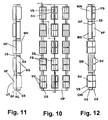
- Fig. 10 shows a view of a connection plate facing the direction of the wall space WR outwardly facing surface with the holding elements.
- the line of sight of Fig. 10 provides a view into the recesses VT and through the openings in the base plate GP on the projections of the connecting structures MV with the groove NU.
- Fig. 11 shows a connection plate with view in the x-direction from the side
- Fig. 12 a sectional view corresponding to the multi-stepped section line XII-XII in Fig. 10 which further shows the structure of the preferred embodiment of the terminal plate.
Landscapes
- Engineering & Computer Science (AREA)
- Architecture (AREA)
- Physics & Mathematics (AREA)
- Electromagnetism (AREA)
- Civil Engineering (AREA)
- Structural Engineering (AREA)
- Moulds, Cores, Or Mandrels (AREA)
- Bipolar Transistors (AREA)
- Crystals, And After-Treatments Of Crystals (AREA)
- Saccharide Compounds (AREA)
- Semiconductor Memories (AREA)
- Surgical Instruments (AREA)
- Forms Removed On Construction Sites Or Auxiliary Members Thereof (AREA)
Description
- Die Erfindung betrifft ein Schalungselement, insbesondere für Mantelbauweise, mit zwei einen Wandraum zwischen sich einschließenden Wandplatten und wenigstens einem die Wandplatten umbindenden Abstandshalter.
- Ein derartiges Wandelement ist beispielsweise aus der
DE 196 32 528 A1 bekannt, wo die Innenflächen der Wandplatten hinterschnittene Vertiefungen aufweisen und auch dem als Kunststoff-Spritzgußteil ausgebildeten Abstandshalter plattenförmige Abschnitte angeordnet sind, welche paßgenau vertikal in die Vertiefungen einsteckbar sind. Es sind auch schwalbenschwanzförmige Nutenquerschnitte z B. aus derDE 20 2004 015 083 U1 bekannt. - Aus der
EP 0 153 660 B1 sind Schalungselemente für Mantelbetonbauweise bekannt, bei welchen an den Innenflächen der Wandplatten regelmäßige Nutenstrukturen ausgebildet sind, in welche parallele Stege an Anschlussplatten eines Abstandhalters eingesteckt und verklebt werden können. Bekannt ist ferner, an den Innenflächen der Wandplatten schwalbenschwanzförmige Vorsprünge auszubilden, über welche Abstandshalter mit komplementären Aussparungen geschoben werden können. - Die
WO 03/097 957 - Die
WO 02/055798 A2 - Die Abstandshalter haben zum einen die Funktion, die beiden Wandplatten zu einem beim Aufbau einer Wand einheitlich zu handhabenden Schalungselement zu verbinden, und müssen zum anderen bei Befüllen des hohlen Wandraums mit Frischbeton die Wandplatten gegen den Druck des eingefüllten Betons zusammenhalten.
- Der vorliegenden Erfindung liegt die Aufgabe zugrunde, ein zuverlässiges und kostengünstiges Schalungselement der einleitend genannten Art anzugeben.
- Diese Erfindung ist im Patentanspruch 1 beschrieben. Die abhängigen Ansprüche enthalten vorteilhafte Ausgestaltungen und Weiterbildungen der Erfindung.
- Durchbrüche durch die Grundplatte in Bereichen der Projektion der Halteflanken auf die Grundplatte sind von besonderem Vorteil für die Herstellung der bevorzugten Ausführungsformen der Grundplatten als Kunststoff-Spritzgussteile. Die Durchbrüche ermöglichen das Eintauchen von Formkemen durch die Anlagefläche der Grundplatte in Richtung der Halteflanken. Insbesondere bei einem gebauten Abstandshalter durch Zusammenfügen wenigstens eines Mittelteils mit zwei separat gefertigten Anschlussplatten ist vorteilhafterweise für die Anschlussplatten ein Spritzgusswerkzeug eingesetzt, welches zwei in Richtung der Flächennormalen der Ebene der Anlagefläche der Grundplatte relativ zueinander verformbare Gussformhälften aufweist und keine weiteren die Form der Anschlussplatten bestimmende bewegte Teile benötigt. Durch die Verfahrbarkeit der Gussformhälften in Richtung der Flächennormalen der Ebene der Anlagefläche der Anschlussplatte an die Wandplatte und durch den Wegfall weiterer formbestimmende bewegter Gussformteile, wie zum Beispiel Schieber, ergeben sich vorteilhafterweise kurze Taktzeiten beim Spritzgießen und eine hohe Standzeit des Spritzgusswekzeugs.
- Erste Formkerne an einer ersten Gussformhälfte der Spritzgussform mit Stirnflächen für die Halteflanken und zweite Formkerne an einer zweiten Gussformhälfte für die Vertiefungen tauchen in entgegengesetzter Richtung in den Formraum und bestimmen mit einander beabstandet gegenüberstehenden Flächen die Wände der Halteelemente. Weitere Kerne an der zweiten Gussformhälfte tauchen entlang der ersten Formkerne bis zu der Grundplatte ein.
- Das Prinzip der gegentauchenden Kerne kann vorteilhafterweise auch eingesetzt sein für Verbindungsstrukturen an der dem Wandraum zu und von den Halteelementen weg weisenden Seite der Anschlussplatten. Insbesondere kann hierbei vorgesehen sein, dass an einigen oder mehreren zweiten Kernen für die Vertiefungen Fortsätze vorgesehen sind, welche am Fußpunkt der Halteelemente an der Grundplatte in Verlängerung der Vertiefungen Öffnungen in der Grundplatte verursachen und auf der dem Wandraum zugewandten Seite der Grundplatte mit gegentauchenden Kernen der ersten Gussformhälfte solche Verbindungsstrukturen definieren.
- Durch die von einer Grundplatte des Abstandhalters weg nach außen, d. h. von dem zwischen den Wandplatten eingeschlossenen Wandraum weg sich verbreiternden Halteelemente der Haltestrukturen ergibt sich vorteilhafterweise eine stabile Verankerung der Haltestrukturen in den Gegenstrukturen, wobei bei kontinuierlicher Aufteilung der Halteelemente in besonders vorteilhafter Weise die Formstabilität sowohl der Halteelemente als auch der hinterschnittenen Abschnitte der Wandplatten gewahrt werden kann. Vorzugsweise erweitern sich die Halteelemente mit im wesentlichen ebenen Halteflanken, so dass im Querschnitt die Halteflanken mit einer Anlageebene der Grundplatte an die Wandplatte eine Trapezform bilden. Der Neigungswinkel der ebenen Halteflanken gegen die vorzugsweise ebene Anlagefläche der Grundplatte liegt vorteilhafterweise zwischen 20 und 45 , vorzugsweise zwischen 25° und 35°. Die Halteflanken können aber auch im Querschnitt gekrümmt verlaufen. Als Anlagefläche der Anschlussplatte bzw. deren Grundplatte an eine Wandplatte sei eine typischerweise im wesentlichen ebene nach außen zu der Innenfläche der Wandplatte hin weisende Einhüllendenfläche der Grundplatte ohne Berücksichtigung der von dieser abstehenden Haltestrukturen verstanden.
- Durch die von der der Grundplatte abgewandten Stirnseite der Halteelemente her eingebrachten Vertiefungen in die Halteelemente kann die Menge für die Abstandshalter bzw. die Grundplatten benötigten Kunststoffs gegenüber einer Ausführungsplattform mit bis zur Stirnfläche massiven Halteelementen erheblich verringert werden, wobei insbesondere die Materialersparnis an der Stirnfläche bei der größten Breite der Halteelemente erzielt werden kann. Die Vertiefungen sind auch spritzgusstechnisch von Vorteil wegen der dadurch verringerbaren Materialdicke.
- Die die Vertiefungen seitlich begrenzenden und die Halteflanken bildenden Seitenwände der Halteelemente können in vorteilhaften Ausführungsformen in ihrem Verlauf von der Grundplatte weg eine gleichbleibende Wandstärke aufweisen. Die Wandstärke kann aber auch variieren, insbesondere sich kontinuierlich verjüngen.
- Von besonderem Vorteil ist, in den Vertiefungen zwischen gegenüber liegenden Seitenwänden Stege vorzugeben, welche die Seitenwände der Halteelemente seitlich abstützen, insbesondere bei in einer Einschieberichtung mit konstantem Querschnitt verlaufenden Halteelementen. Derartige vorzugsweise wandförmige Stege können insbesondere an Enden von Halteelementen und oder als Zwischenwandstege im Verlauf von solchen Halteelementen vorgegeben sein.
- Vorteilhafterweise sind eine Mehrzahl von Halteelementen in einer Einschieberichtung beabstandet aufeinanderfolgend und fluchtend und/oder quer zur Einschieberichtung beabstandet, vorzugsweise in mehreren parallelen Reihen mit jeweils mehreren Halteelementen angeordnet. Zwischen in Einschieberichtung aufeinander folgenden Halteelementen sind vorteilhafterweise in Einschieberichtung verlaufende Zwischenstege, vorzugsweise von der Grundplatte abstehend vorgesehen. In vorteilhafter Ausführung sind genau drei Reihen paralleler Reihen von Halteelementen vorgesehen.
- Auf der den Halteelementen abgewandten Seite der Anschlussplatte sind vorteilhafterweise von der Grundplatte in den Wandraum abstehend aussteifende Stege oder Rippen ausgebildet, welche seitlich von dem wenigstens einen Mittelteil wegführen. Die aussteifenden Stege verlaufen vorteilhafterweise vor, nach und/oder zwischen in Einschieberichtung beabstandet aufeinanderfolgenden Halteelementen auf der gegenüberliegenden Seite der Grundplatte.
- Die Wandplatten bestehen vorteilhafterweise in an sich gebräuchlicher Weise aus wärmeisolierendem Hartschaum, beispielsweise geschäumtem Polystyrol. Es können auch unterschiedliche Wandplatten für Innenseite und Außenseite einer Wand vorgesehen sein. Die Gegenstrukturen können in gleichfalls an sich gebräuchlicher Weise als parallele hinterschnittene Nuten in der inneren, d. h. der dem Wandraum zuweisenden Fläche der Wandplatten ausgebildet, wobei das Einschieben der Abstandshalter durch Anschläge an der Wandplatte und/oder am Abstandshalter begrenzt sein kann.
- Die Erfindung ist nachfolgend anhand bevorzugter Ausführungsbeispiele unter Bezugnahme auf die Abbildungen nach eingehend veranschaulicht. Dabei zeigt
- Fig. 1
- eine Zusammenstellung von Einzelteilen eines Schalungselements,
- Fig. 2
- eine zusammengesetztes Schalungselement in Schrägansicht,
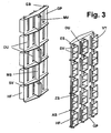
- Fig. 3
- Wandplatten in Schrägansicht von innen und außen,
- Fig. 4
- einen Abstandshalter mit Blick in Wandrichtung,
- Fig. 5
- den Abstandshalter nach
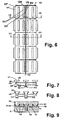
Fig. 4 in Draufsicht, - Fig. 6
- einen Blick auf die Innenfläche einer Anschlussplatte,
- Fig. 7
- einen Schnitt durch eine Anschlussplatte entlang VII-VII von
Fig. 6 , - Fig. 8
- einen Schnitt durch eine Anschlussplatte entlang VIII-VIII von
Fig. 6 - Fig. 9
- einen Schnitt wie in
Fig. 8 mit Spritzgussform - Fig. 10
- einen Blick auf die Außenfläche einer Anschlussplatte
- Fig. 11
- eine Seitenansicht zu
Fig. 10 - Fig. 12
- einen Schnitt XII-XII von
Fig. 10 -
Fig. 1 zeigt in Schrägansicht eine Zusammenstellung von Teilen einer bevorzugten Ausführungsform eines Schalungselements nach der Erfindung. ZuFig. 2 ist das fertig zusammengebaute Schalungselement in Schrägansicht dargestellt. - Das Schalungselement nach
Fig. 2 ist zusammengesetzt aus zwei Wandplatten WP aus einem vorzugsweise wärmeisolierendem Hartschaum, insbesondere aus geschäumten Polystyrol. Es können auch für Innenseite und Außenseite einer Wand Wandplatten unterschiedlicher Form oder unterschiedlicher Materialien vorgesehen sein. Die beiden Wandplatten sind im wesentlichen quaderförmig. Die Außenflächen der Wandplatten sind im wesentlichen eben. An den in Längsrichtung x entgegengesetzten Endflächen der Wandplatten sind komplementäre Strukturen HS1 bzw. HS2, beispielsweise Nuten bzw. Stege ausgebildet, über welche in Längsrichtung x aufeinanderfolgende Schalungselemente in Querrichtung y exakt zueinander ausgerichtet werden können. In entsprechender Weise sind an den Oberseiten der Wandplatten WP weitere Strukturen VS1 und an den Unterseiten der Wandplatten in der Skizze nicht sichtbare Strukturen VS 2 ausgebildet, über welche vertikal aufeinanderfolgende Reihen von Schalungselementen in Querrichtung y und in Längsrichtung x exakt zueinander ausgerichtet werden können. - Die Wandplatten WP schließen einen Wandraum WR zwischen sich ein. Die dem Wandraum zu weisenden Innenflächen IF weisen Gegenstrukturen GS zu Haltestrukturen PS an den Abstandshaltern auf. Die Gegenstrukturen sind vorzugsweise vertikal verlaufende hinterschnittene Nuten, in welche die Haltestrukturen der Abstandshalter in z-Richtung von oben einschiebbar sind, wodurch eine Fixierung der beiden Wandplatten relativ zueinander erfolgt. Die Einschiebtiefe kann vorteilhafterweise durch einen Anschlag in den Innenflächen IF der Wandplatten und/oder an den Abstandshaltern erfolgen. Die Gegenstrukturen GS können vorteilhafterweise in x-Richtung an der Innenfläche kontinuierlich fortgesetzt sein, so dass die Abstandshalter mit den Haltestrukturen an mehreren Positionen in die Gegenstrukturen eingeschoben werden können. In anderer Ausführung können auch wenige konkrete Positionen vorgegeben sein. Die Gegenstrukturen oder sonstige Reliefstrukturen in nicht von Abstandshaltern belegten Flächenteilen der Innenflächen IF können zur besseren Verankerung der Wandplatten mit dem in dem Wandraum eingefüllten und aushärtendem Beton dienen. Die Abstandshalter AH sind ihrerseits zusammengesetzt aus zwei flachen Anschlussplatten AP und einem diese verbindenden flachen Mittelteil MT. Ein Abstandshalter ist in detaillierter Darstellung in verschiedenen Ansichten in
Fig. 4 und Fig. 5 skizziert. - Der Abstandshalter enthält zwei über die Haltestrukturen in den Gegenstrukturen der Wandplatten-Innenflächen mechanisch verankerbare Anschlussplatten AP der in
Fig. 3 skizzierten Art und ein Mittelteil MT, welches über Verbindungsstrukturen MV der Anschlussplatten mit diesen verbindbar ist, z. B. durch Einrasten und/oder vorzugsweise durch Einschieben in z-Richtung. Vorzugsweise werden zuerst zwei Anschlussplatten und ein Mittelteil zu einem Abstandshalter verbunden und dieser dann mit den Haltestrukturen in die Gegenstrukturen der Innenflächen zweier Wandplatten eingeschoben. Durch die aus Anschlussplatten und Mittelteil gebaute Form des Abstandshalters können die Anschlussplatten auch vor der Verbindung mit dem Mittelteil in die Gegenstrukturen oder Wandplatten eingeschoben oder bereits bei der Herstellung der Wandplatten in diese integriert werden, so dass eine Verbindung zweier Wandplatten durch Einschieben des Mittelteils in die vormontierten oder integrierten Anschlussplatten erfolgt. Die beiden Anschlussplatten sind vorzugsweise formidentisch. - Das Mittelteil bildet einen weitgehend offenen Rahmen mit Vertikalstegen MLS und Querstegen MQS, wobei in dem obersten Quersteg Aufnahmen BA für Stahlbewehrungen des Betonwandkerns vorbereitet sind. Das Mittelteil ist vorzugsweise als einstückiges Kunststoff-Spritzgussteil ausgeführt.
- Die Anschlussplatten sind vorteilhafterweise gleichfalls als einstückige Kunststoff-Spritzgussteile hergestellt, wobei wesentliche Merkmale der vorliegenden Erfindung insbesondere die Ausbildung der Anschlussplatten betreffen. Verschiedene, teilweise auch geschnittene Darstellungen einer Anschlussplatte sind in
Fig. 6 bis Fig. 12 skizziert. Die Anschlussplatten enthalten eine Grundplatte GP, an deren nach außen, d. h. in y-Richtung vom Wandraum WR weg weisender Außenseite die Haltestrukturen PS angeordnet sind und an deren nach innen, d. h. zu dem Wandraum WR hin weisender Innenseite die Verbindungsstrukturen MV zur Verbindung mit dem Mittelteil ausgebildet sind. - Durch Aussteifungen auf der Innenseite der Grundplatte GP kann die Grundplatte GP selbst mit in Querrichtung y geringer Wandstärke ausgeführt sein. Im skizzierten Beispiel ist das Mittelteil MT in Längsrichtung x in der Mitte der Anschlussplatte mit dieser verbunden. Aussteifungsstege AS erstrecken sich mit abnehmender Höhe über der Grundplatte von der Mitte in x-Richtung nach außen zu den Rändern der Grundplatte. Solche Aussteifungsstege sind vorteilhafterweise am oberen und am unteren Rand der Grundplatte und in mehreren Zwischenpositionen in y-Richtung ausgebildet. Die zu einer x-y-Ebene parallel verlaufenden Aussteifungsstege AS sind vorteilhafterweise mit einem in einer y-z-Ebene liegenden vertikalen, Mittelsteg MS verbunden. Der Mittelsteg MS besteht in dem skizzierten bevorzugten Beispiel aus mehreren in z-Richtung verlaufenden Stegabschnitten, welche im Bereich der Verbindungsstrukturen voneinander beabstandet sind.
- Die Grundplatte GP ist nicht notwendigerweise, aber vorzugsweise eben und bestimmt mit ihrer Außenseite eine ebene Anlagefläche AE zwischen Anschlussplatte AP und Innenfläche IP einer Wandplatte. Eine fiktive Ebene AE sei auch bei nicht ebener Außenseite der Grundplatte als mittlere Anlagefläche angenommen. Die Außenfläche kann insbesondere auch im Ausgangszustand mit den seitlichen Randbereichen zum Wandraum hin gewölbt sein, so dass beim Einschieben der Haltestrukturen in die Gegenstrukturen der ebenen Innenwandfläche der Wandplatte eine Verbiegung der Grundplatte und eine elastische Vorspannung an den Randbereichen entsteht.
- Die Haltestrukturen an der Außenseite der Grundplatte enthalten eine Mehrzahl von Halteelementen, welche in drei in Einschieberichtung z verlaufenden, in Längsrichtung x voneinander beabstandeten Reihen mit jeweils mehreren, im Beispielsfall fünf Halteelementen regelmäßig angeordnet sind. Die Zahl von genau drei Reihen von Halteelementen ist besonders vorteilhaft bezüglich einer festen Verankerung der Anschlussplatten in den Innenflächen der Wandplatten bei gleichzeitig geringer Schwächung des Wandplattenmaterials bei den Hinterschneidungen.
- Ferner kann in vorteilhafter Weiterbildung ein Abstandshalter an der Stoßstelle zweier in Längsrichtung aufeinander folgenden Wandplatten mit der mittleren Reihe von Halteelementen in eine je zur Hälfte von beiden Wandplatten gebildeten hinterschnittene Nut eingreifen, wofür an den Wandplatten in Längsrichtung endständig an der Platteninnenfläche jeweils ein halber Querschnitt einer solchen Nut ausgebildet ist.
- Die Halteelemente sind ausgehend von einem Fußbereich FB an der Grundplatte GP von dieser weg nach außen führend durch auseinander strebende Halteflanken HF in Richtung einer von der Grundplatte beabstandeten Stirnfläche SF verbreitert. Die Halteflanken HF liegen an korrespondierenden Gegenflanken der hinterschnittenen Nuten der Gegenstrukturen an und stützen die Anschlussplatten gegen Auszehen der Haltestrukturen aus den Gegenhaltestrukturen ab.
- Die Halteflanken bilden im skizzierten bevorzugten Beispiel ebene Flächen, welche gegen die ebene Anlagefläche AE um einen Winkel zwischen 45° und 75°, vorzugsweise 55° und 65° geneigt sind. In der Draufsicht nach
Fig. 7 und Fig. 8 bilden die Halteflanken der Außenkontur des Querschnitts der Halteelemente Seitenkanten einer Trapezform. Die Halteflanken können auch gekrümmt verlaufen. - In den Halteelementen sind von der Stirnfläche SF her, an welcher die Halteelemente die größte Ausdehnung in Längsrichtung x besitzen, Vertiefungen VT ausgebildet, welche bis zu dem Fußbereich der Halteelemente an der Grundplatte reichen können. Die Wandstärke der Wände der Halteelemente zwischen den Vertiefungen und den Halteflanken kann vorteilhafterweise weitgehend konstant sein, kann aber auch vom Fußbereich zur Stirnfläche hin abnehmen. Die Halteflanken eines Halteelements verlaufen vorzugsweise in Einschieberichtung z im Querschnitt gleichbleibend über die Höhe des Halteelements in z-Richtung. Die mehreren Halteelemente einer Reihe weisen in z-Richtung fluchtende Halteflanken auf.
- Eine vorteilhaft geringe Wandstärke für die Seitenwände kann insbesondere dann gewählt werden, wenn zwischen gegenüber liegenden Seitenwänden eines Halteelements aussteifende Stegwände SV ausgebildet sind, welche ein Umbiegen der Wände mit den Halteflanken unter der Einwirkung ausziehender Kräfte, z. B. durch statischen Druck eingefüllten Frischbetons, verhindern. Im skizzierten bevorzugten Beispiel weisen die Halteelemente an ihren oberen und unteren Enden jeweils solche Stegwände SV auf. Eine oder mehrere solche Stegwände können je nach Höhe der Halteelemente in z-Richtung an Zwischenpositionen vorgesehen sein.
- Zwischen in einer Reihe in z-Richtung aufeinanderfolgenden Halteelementen können vorteilhafterweise in einer y-z-Ebene im Fußbereich der Halteelemente verlaufende Zwischenstege ZS ausgebildet sein. Die Zwischenstege ZS sind vorzugsweise mit oberen und/oder unteren Stegwänden SV eines Halteelements verbunden. Am oberen und unteren Ende der Grundplatte sind entsprechend ausgerichtete Endstege ES vorgesehen.
- Die Grundplatte GP weist in Bereichen der Projektion der Halteflanken HF auf die Anlageebene AE Durchbrüche DU auf. Diese Durchbrüche sind von besonderem Vorteil für die Herstellung einer Anschlussplatte als Kunststoff-Spritzgussteil in einer Spritzgussform. Die Durchbrüche ermöglichen die Vorgabe der Halteflanken an Endflächen von durch die Grundplatte von deren Innenseite her durchtauchenden Formkernen. In Verbindung mit von der Außenseite der Anschlussplatte in der Gussform gegentauchenden Formkernen kann vorteilhafterweise eine Gussform eingesetzt werden, welche in der Skizze nach
Fig. 9 in einemFig. 8 entsprechenden Schritt durch eine Anschlussplatte schematisch dargestellt ist. - Die Form besteht aus zwei Formhälften FI und FA, welche im wesentlichen in Richtung der Flächennormalen der ebenen Anlagefläche AE, d. h. in y-Richtung zum Öffnen und Schließen der Gussform relativ zueinander verfahren werden können. Da die Anschlussplatte in dieser Verfahrrichtung ihre geringste Abmessung aufweist, ergibt sich ein besonders kurzer Verfahrweg, was eine niedrige Taktzeit begünstigt.
- Über die Durchbrüche DU in der Grundplatte GP ragen Formkerne FH der auf der Innenseite der Grundplatte liegenden ersten Formhälfte FI auf die Außenseite der Grundplatte und bestimmen dort die Form der Halteflanken HF. Zwischen diesen ersten Formkernen FH und zweiten Formkernen FV an der zweiten Formhälfte FA sind die Seitenwände der Halteelemente ausgebildet. Weitere Formkerne FZ an der zweiten Formhälfte FA tauchen zwischen jeweils zwei ersten Formkernen FH bis zur Grundplatte GP ein.
- Das Prinzip gegentauchender Formkerne ist im skizzierten Beispiel auch vorteilhaft eingesetzt für die Ausbildung der Verbindungsstruktur MV zum Mittelteil. Hierfür sind Formkerne FV-M zur Erzeugung der Vertiefung VT in Halteelementen der mittleren Reihe an der auf der Außenseite der Grundplatte GP liegenden Formhälfte FA durch die Grundplatte hindurch durch Fortsätze FS verlängert und erzeugen Durchbrüche am Boden der Vertiefung VT von im Beispiel einigen, aber nicht allen Halteelementen der mittleren Reihe. Zwischen der ersten Formhälfte und dem Fortsatz FS werden die Verbindungsstrukturen MV mit eine hinterschnittene Führungsnut NU für das Mittelteil bildenden Vorsprüngen VS an zwei von der Grundplatte abstehenden Wandabschnitte WN ausgebildet. Die Enden der Wandabschnitte WN in z-Richtung sind über eine Querwand QW untereinander und mit dem mittleren Steg MS verbunden. Die hinterschnittene Führungsnut begünstigt eine vorteilhafte Spritzgussform für das Mittelteil.
- Die hinterschnittene Nut und die vertikalen Stegabschnitte MS definieren eine Führung für das Mittelteil, welches durch Einschieben in diese Führungen in z-Richtung die beiden Wandplatten miteinander verbindet und mit diesen den Abstandshalter bildet.
- Eine Abwandlung der Verbindungsstrukturen sieht vor, dass zwischen den Wandabschnitten WN der mittlere Steg in z-Richtung durchgeführt ist, wofür der Fortsatz FS in zwei den Steg zwischen sich einschließende flache Fortsätze unterteilt ist, welche bis zu den Vorsprüngen in y-Richtung reichen und mit einem die Nut bildenden gegentauchenden Formkern an der ersten Formhälfte kooperieren.
- Die übrigen Kernformen an den beiden Formhälften betreffen keine Hinterschneidungen und sind als Standardfälle von Spritzgussformen ohne weiteres aus den Skizzen ableitbar und daher nicht weiter im Detail erläutert. Die durch die Grundplatte hindurchtauchenden Formkerne FH und FS ermöglichen vorteilhafterweise die Ausführung beider Formhälften mit bezüglich der jeweiligen Formhälfte feststehenden Formkernen und dem Verzicht auf die Form der Anschlussplatte bestimmende relativ zu beiden Formhälften zu bewegende Kerne als Schieber oder dergleichen.
-
Fig. 10 zeigt eine Ansicht einer Anschlussplatte mit Blickrichtung auf die vom Wandraum WR weg nach außen weisende Fläche mit den Halteelementen. Die Blickrichtung derFig. 10 bietet den Blick in die Vertiefungen VT und durch die Durchbrüche in der Grundplatte GP hindurch auf die Vorsprünge der Verbindungsstrukturen MV mit der Nut NU. -
Fig. 11 zeigt eine Anschlussplatte mit Blick in x-Richtung von der Seite,Fig. 12 eine Schnittansicht entsprechend der mehrfach gestuften Schnittlinie XII-XII inFig. 10 , welcher weiter den Aufbau der bevorzugten Ausführungsform der Anschlussplatte zeigt. - Die vorstehend und die in den Ansprüchen angegebenen sowie die den Abbildungen entnehmbaren Merkmale sind sowohl einzeln als auch in verschiedener Kombination vorteilhaft realisierbar.
Claims (18)
- Schalungselement, insbesondere für Mantelbetonbauweise, mit zwei einen Wandraum zwischen sich einschließenden Wandplatten (WP) und wenigstens einen die Wandplatten (WP) verbindenden Abstandshalter (AH) welcher zwei Anschlussplatten (AP) und wenigstens ein diese verbindendes Mittelteil (MT) enthält, wobei die Anschlussplatten (AP) mit von einer Grundplatte (GP) nach außen vom Wandraum (WP) weg weisenden Haltestrukturen (PS) in hinterschnittene komplementäre Gegenstrukturen (GS) in den Innenflächen (IF) der Wandplatten (WP) eingreifen, wobei die Haltestrukturen (PS) Halteelemente aufweisen, welche sich von einem Fußbereich (FB) an der Grundplatte (GP) von dieser weg mit seitlich auseinanderstrebenden Halteflanken (HF) in Richtung einer von der Grundplatte (GP) abgewandten Stirnseite (SF) verbreitern, dadurch gekennzeichnet, dass die Grundplatte (GP) in Bereichen der Projektion der Halteflanken (HF) auf die Grundplatte (GP) Durchbrüche (DU) aufweist.
- Schalungselement nach Anspruch 1, dadurch gekennzeichnet, dass die Haltestrukturen (PS) in einer Einschieberichtung (z) parallel zur Innenfläche (IF) der Wandplatte (WP) in die Gegenstrukturen (GS) einschiebbar sind.
- Schalungselement nach Anspruch 2, dadurch gekennzeichnet, dass die Halteelemente einen in Einschieberichtung (7) gleichbleibenden Querschnitt aufweisen.
- Schalungselement nach Anspruch 2 oder 3, dadurch gekennzeichnet, dass mehrere in Einschieberichtung (7) aufeinander folgende Halteelemente zueinander beabstandet und in Einschieberichtung miteinander fluchtend angeordnet sind.
- Schalungselement nach Anspruch 4, dadurch gekennzeichnet, dass zwischen in Einschieberichtung (7) beabstandet aufeinander folgenden Halteelementen einer Reihe von der Grundplatte abstehende Zwischenstege (ZS) angeordnet sind.
- Schalungselement nach Anspruch 4 oder 5, dadurch gekennzeichnet, dass mehrere Halteelemente quer zur Einschieberichtung (7) beabstandet angeordnet sind.
- Schalungselement nach Anspruch 6, dadurch gekennzeichnet, dass Halteelemente in mehreren, vorzugsweise drei parallelen Reihen angeordnet sind.
- Schalungselement nach einem der Ansprüche 1 bis 7, dadurch gekennzeichnet, dass die Halteelemente von der Stirnseite (SF) her wenigstens eine Vertiefung (VT) zwischen die Halteflanken (HF) bildenden Seitenwänden aufweisen.
- Schalungselement nach Anspruch 8,dadurch gekennzeichnet, dass die Vertiefung (VT) bis zum Fußbereich (FB) eines Halteelements.reicht.
- Schalungselement nach Anspruch 6 und 9, dadurch gekennzeichnet, dass die Vertiefung (VT) in wenigstens einen Durchbruch durch die Grundplatte (GP) im Fußbereich (FB) des Halteelements mündet.
- Schalungselement nach einem der Ansprüche 8 bis 10, dadurch gekennzeichnet, dass die Seitenwände der Halteelemente über ihren zumindest überwiegenden Verlauf eine im wesentlichen konstante Wandstärke aufweisen.
- Schalungselement nach einem der Ansprüche 8 bis 10, dadurch gekennzeichnet, dass in der Vertiefung (VT) wenigstens eine quer zur Einschieberichtung verlaufende Stegwand (SV) zwischen gegenüber liegenden Seitenwänden eines Halteelements ausgebildet ist.
- Schalungselement nach einem der Ansprüche 1 bis 12, dadurch gekennzeichnet, dass der Abstandshalter (AH) aus separat vorgefertigten Anschlussplatten (AP) und das Mittelteil (MT) zusammengebaut ist.
- Schalungselement nach einem der Ansprüche 1 bis 13, dadurch gekennzeichnet, dass die Ausdehnung des Mittelteils (MT) in Längsrichtung (X) der Wandplatten (WP) kleiner ist als die Breite der Anschlussplatten (AP) vorzugsweise kleiner als die Ausdehnung eines Halteelements in Längsrichtung.
- Schalungselement nach Anspruch 14, dadurch gekennzeichnet, dass eine Grundplatte (GP) einer Anschlusssplatte (AP) auf der dem Wandraum (WR) zugewandten Seite von einem Mittelsteg (MS) seitlich weg führende Aussteifungsstege (AS) aufweist.
- Schalungselement nach Anspruch 15, dadurch gekennzeichnet, dass die Aussteifungsstege (AS) in Einschieberichtung (z) gegen die Halteelemente versetzt angeordnet sind.
- Schalungselement nach einem der Ansprüche 1 bis 16, dadurch gekennzeichnet, dass die Anschlussplatten (AP) als Kunststoff-Spritzgussteile ausgebildet sind.
- Schalungselemen nach Anspruch 17, dadurch gekennzeichnet, dass die Abschlussplatten (AP) mit einem in Richtung der Flächennormale der Grundplatte (GP) zu öffnenden und zu schließenden zweiteiligen Spritzgusswerkzeug (FI, FA) ohne retativ zu beiden Formhälften (FI, FA) bewegliche, die Form der Anschlussplatte (AP) bestimmende Werkzeugteile herstellbar sind.
Priority Applications (1)
| Application Number | Priority Date | Filing Date | Title |
|---|---|---|---|
| PL06024261T PL1849927T3 (pl) | 2005-12-22 | 2006-11-23 | Element szalunkowy |
Applications Claiming Priority (1)
| Application Number | Priority Date | Filing Date | Title |
|---|---|---|---|
| DE102005062156A DE102005062156A1 (de) | 2005-12-22 | 2005-12-22 | Schalungselement |
Publications (2)
| Publication Number | Publication Date |
|---|---|
| EP1849927A1 EP1849927A1 (de) | 2007-10-31 |
| EP1849927B1 true EP1849927B1 (de) | 2009-09-02 |
Family
ID=38108852
Family Applications (1)
| Application Number | Title | Priority Date | Filing Date |
|---|---|---|---|
| EP06024261A Not-in-force EP1849927B1 (de) | 2005-12-22 | 2006-11-23 | Schalungselement |
Country Status (4)
| Country | Link |
|---|---|
| EP (1) | EP1849927B1 (de) |
| AT (1) | ATE441764T1 (de) |
| DE (2) | DE102005062156A1 (de) |
| PL (1) | PL1849927T3 (de) |
Family Cites Families (6)
| Publication number | Priority date | Publication date | Assignee | Title |
|---|---|---|---|---|
| DE3405736A1 (de) * | 1984-02-17 | 1985-08-22 | Ipa-Isorast International S.A., Panama | Schalungselement fuer die mantelbetonbauweise sowie waermedaemmplatte |
| DE19632528A1 (de) * | 1996-08-13 | 1998-02-19 | Ubs Uni Bau System Gmbh | Hartschaum-Schalungselement |
| US20010029717A1 (en) * | 1997-02-04 | 2001-10-18 | Spakousky John G. | Composite building block with modular connective structure |
| DE19909460A1 (de) * | 1999-03-04 | 2000-11-02 | Ubs Uni Bau System Gmbh | Schalungssystem |
| AU2003222710A1 (en) * | 2002-05-18 | 2003-12-02 | Bvb Ag | Spacer for sheathing elements |
| DE202004015083U1 (de) * | 2004-06-12 | 2004-12-30 | Brüssow, Jürgen | Schalungselemente aus Hartschaum für die Mantelbetonbauweise |
-
2005
- 2005-12-22 DE DE102005062156A patent/DE102005062156A1/de not_active Withdrawn
-
2006
- 2006-11-23 AT AT06024261T patent/ATE441764T1/de active
- 2006-11-23 EP EP06024261A patent/EP1849927B1/de not_active Not-in-force
- 2006-11-23 PL PL06024261T patent/PL1849927T3/pl unknown
- 2006-11-23 DE DE502006004734T patent/DE502006004734D1/de active Active
Also Published As
| Publication number | Publication date |
|---|---|
| ATE441764T1 (de) | 2009-09-15 |
| DE502006004734D1 (de) | 2009-10-15 |
| DE102005062156A1 (de) | 2007-06-28 |
| PL1849927T3 (pl) | 2010-04-30 |
| EP1849927A1 (de) | 2007-10-31 |
Similar Documents
| Publication | Publication Date | Title |
|---|---|---|
| DE2628703C3 (de) | Anordnung und Verfahren zur Herstellung von Profilen, insbesondere für Fenster und Türen | |
| DE69832087T2 (de) | Kunststoffpalette und verfahren zum herstellen solcher paletten sowie anderer kunststoffprodukte | |
| DE2802237C2 (de) | Spritzgießform zum Herstellen von aus mindestens zwei verschiedenen Kunststoffmassen bestehenden und mindestens zwei unterschiedliche Bereiche aufweisenden Spritzgußteilen | |
| EP0371917B1 (de) | Aufsatzrahmen für eine Entwässerungsrinne | |
| DE3037177A1 (de) | Vorrichtung zum bilden einer ausnehmung in betonfertigteilen o.dgl. | |
| WO1998006911A1 (de) | Schalungselement und wandaufbau mit solchen schalungselementen | |
| AT402084B (de) | Verlorenes schalungselement | |
| EP1642698A2 (de) | Verfahren und Vorrichtung zum Ausbilden eines Abschnitts eines kastenförmigen Behältnisses | |
| DE202007010508U1 (de) | Seilschlaufenkasten | |
| EP1849927A1 (de) | Schalungselement | |
| EP0139215B1 (de) | Schalung mit beweglichen Teilen für Beton-Fertigteile | |
| DE2916005C2 (de) | Formstück für die Erzeugung von Aussparungen an der Oberfläche von Beton-Bauteilen bei deren Herstellung | |
| EP0738661A1 (de) | Palette aus Kunststoff, Verfahren und Vorrichtung zu ihrer Herstellung | |
| DE2543829A1 (de) | Verfahren zum herstellen von einstueckigen gitterrostfeldern, insbesondere stabrostfeldern, sowie danach hergestelltes gitterrost-, insbesondere stabrostfeld | |
| DE69609027T2 (de) | Vorrichtung zum Zusammenbau von nacheinanderfolgend gleichförmigen, vertikalen und U-förmigen Schalungselementen, die als leichte, verlorene Schalung verwendet werden | |
| EP0088875A1 (de) | Für die Mantelbetonbauweise bestimmtes grossformatiges Schalungselement | |
| CH718329A2 (de) | Abschalleiste, Überdeckungsabschalung, Abschalungselement, Schalungsanordnung, Verfahren zum Aufbau einer Schalungsanordnung und Verfahren zum Herstellen einer Abschalleiste. | |
| WO2003097957A1 (de) | Distanzhalter für schalungselemente | |
| CH718328A2 (de) | Abschalleiste, Überdeckungsabschalung, Abschalungselement, Schalungsanordnung, Verfahren zum Aufbau einer Schalungsanordnung und Verfahren zum Herstellen einer Abschalleiste. | |
| DE3502415A1 (de) | Einrichtung und verfahren zur herstellung von schalungseinheiten | |
| DE3232576C2 (de) | ||
| DE2334046C3 (de) | Form zum Herstellen von Betonformteilen mit mindestens einem in Längsrichtung verlaufenden Hohlraum | |
| EP1676684B1 (de) | Verfahren zur Herstellung eines Bausteins | |
| EP0246647A2 (de) | Bauelement | |
| DE2722791C2 (de) | Verfahren zur Herstellung von Verbundprofilen, insbesondere für Fenster und Türen |
Legal Events
| Date | Code | Title | Description |
|---|---|---|---|
| PUAI | Public reference made under article 153(3) epc to a published international application that has entered the european phase |
Free format text: ORIGINAL CODE: 0009012 |
|
| AK | Designated contracting states |
Kind code of ref document: A1 Designated state(s): AT BE BG CH CY CZ DE DK EE ES FI FR GB GR HU IE IS IT LI LT LU LV MC NL PL PT RO SE SI SK TR |
|
| AX | Request for extension of the european patent |
Extension state: AL BA HR MK YU |
|
| 17P | Request for examination filed |
Effective date: 20080502 |
|
| 17Q | First examination report despatched |
Effective date: 20080603 |
|
| AKX | Designation fees paid |
Designated state(s): AT BE BG CH CY CZ DE DK EE ES FI FR GB GR HU IE IS IT LI LT LU LV MC NL PL PT RO SE SI SK TR |
|
| GRAP | Despatch of communication of intention to grant a patent |
Free format text: ORIGINAL CODE: EPIDOSNIGR1 |
|
| GRAS | Grant fee paid |
Free format text: ORIGINAL CODE: EPIDOSNIGR3 |
|
| GRAA | (expected) grant |
Free format text: ORIGINAL CODE: 0009210 |
|
| AK | Designated contracting states |
Kind code of ref document: B1 Designated state(s): AT BE BG CH CY CZ DE DK EE ES FI FR GB GR HU IE IS IT LI LT LU LV MC NL PL PT RO SE SI SK TR |
|
| REG | Reference to a national code |
Ref country code: CH Ref legal event code: EP |
|
| REG | Reference to a national code |
Ref country code: IE Ref legal event code: FG4D Free format text: LANGUAGE OF EP DOCUMENT: GERMAN |
|
| REF | Corresponds to: |
Ref document number: 502006004734 Country of ref document: DE Date of ref document: 20091015 Kind code of ref document: P |
|
| REG | Reference to a national code |
Ref country code: RO Ref legal event code: EPE |
|
| PG25 | Lapsed in a contracting state [announced via postgrant information from national office to epo] |
Ref country code: LT Free format text: LAPSE BECAUSE OF FAILURE TO SUBMIT A TRANSLATION OF THE DESCRIPTION OR TO PAY THE FEE WITHIN THE PRESCRIBED TIME-LIMIT Effective date: 20090902 Ref country code: SE Free format text: LAPSE BECAUSE OF FAILURE TO SUBMIT A TRANSLATION OF THE DESCRIPTION OR TO PAY THE FEE WITHIN THE PRESCRIBED TIME-LIMIT Effective date: 20090902 Ref country code: FI Free format text: LAPSE BECAUSE OF FAILURE TO SUBMIT A TRANSLATION OF THE DESCRIPTION OR TO PAY THE FEE WITHIN THE PRESCRIBED TIME-LIMIT Effective date: 20090902 |
|
| PGFP | Annual fee paid to national office [announced via postgrant information from national office to epo] |
Ref country code: AT Payment date: 20091120 Year of fee payment: 4 |
|
| NLV1 | Nl: lapsed or annulled due to failure to fulfill the requirements of art. 29p and 29m of the patents act | ||
| LTIE | Lt: invalidation of european patent or patent extension |
Effective date: 20090902 |
|
| PG25 | Lapsed in a contracting state [announced via postgrant information from national office to epo] |
Ref country code: NL Free format text: LAPSE BECAUSE OF FAILURE TO SUBMIT A TRANSLATION OF THE DESCRIPTION OR TO PAY THE FEE WITHIN THE PRESCRIBED TIME-LIMIT Effective date: 20090902 Ref country code: SI Free format text: LAPSE BECAUSE OF FAILURE TO SUBMIT A TRANSLATION OF THE DESCRIPTION OR TO PAY THE FEE WITHIN THE PRESCRIBED TIME-LIMIT Effective date: 20090902 Ref country code: LV Free format text: LAPSE BECAUSE OF FAILURE TO SUBMIT A TRANSLATION OF THE DESCRIPTION OR TO PAY THE FEE WITHIN THE PRESCRIBED TIME-LIMIT Effective date: 20090902 |
|
| PG25 | Lapsed in a contracting state [announced via postgrant information from national office to epo] |
Ref country code: CY Free format text: LAPSE BECAUSE OF FAILURE TO SUBMIT A TRANSLATION OF THE DESCRIPTION OR TO PAY THE FEE WITHIN THE PRESCRIBED TIME-LIMIT Effective date: 20090902 |
|
| REG | Reference to a national code |
Ref country code: IE Ref legal event code: FD4D |
|
| PG25 | Lapsed in a contracting state [announced via postgrant information from national office to epo] |
Ref country code: ES Free format text: LAPSE BECAUSE OF FAILURE TO SUBMIT A TRANSLATION OF THE DESCRIPTION OR TO PAY THE FEE WITHIN THE PRESCRIBED TIME-LIMIT Effective date: 20091213 Ref country code: IE Free format text: LAPSE BECAUSE OF FAILURE TO SUBMIT A TRANSLATION OF THE DESCRIPTION OR TO PAY THE FEE WITHIN THE PRESCRIBED TIME-LIMIT Effective date: 20090902 Ref country code: CZ Free format text: LAPSE BECAUSE OF FAILURE TO SUBMIT A TRANSLATION OF THE DESCRIPTION OR TO PAY THE FEE WITHIN THE PRESCRIBED TIME-LIMIT Effective date: 20090902 Ref country code: IS Free format text: LAPSE BECAUSE OF FAILURE TO SUBMIT A TRANSLATION OF THE DESCRIPTION OR TO PAY THE FEE WITHIN THE PRESCRIBED TIME-LIMIT Effective date: 20100102 Ref country code: EE Free format text: LAPSE BECAUSE OF FAILURE TO SUBMIT A TRANSLATION OF THE DESCRIPTION OR TO PAY THE FEE WITHIN THE PRESCRIBED TIME-LIMIT Effective date: 20090902 Ref country code: PT Free format text: LAPSE BECAUSE OF FAILURE TO SUBMIT A TRANSLATION OF THE DESCRIPTION OR TO PAY THE FEE WITHIN THE PRESCRIBED TIME-LIMIT Effective date: 20100104 |
|
| REG | Reference to a national code |
Ref country code: PL Ref legal event code: T3 |
|
| BERE | Be: lapsed |
Owner name: BVB A.G. Effective date: 20091130 |
|
| PG25 | Lapsed in a contracting state [announced via postgrant information from national office to epo] |
Ref country code: SK Free format text: LAPSE BECAUSE OF FAILURE TO SUBMIT A TRANSLATION OF THE DESCRIPTION OR TO PAY THE FEE WITHIN THE PRESCRIBED TIME-LIMIT Effective date: 20090902 |
|
| PG25 | Lapsed in a contracting state [announced via postgrant information from national office to epo] |
Ref country code: MC Free format text: LAPSE BECAUSE OF NON-PAYMENT OF DUE FEES Effective date: 20091130 |
|
| PLBE | No opposition filed within time limit |
Free format text: ORIGINAL CODE: 0009261 |
|
| STAA | Information on the status of an ep patent application or granted ep patent |
Free format text: STATUS: NO OPPOSITION FILED WITHIN TIME LIMIT |
|
| PG25 | Lapsed in a contracting state [announced via postgrant information from national office to epo] |
Ref country code: DK Free format text: LAPSE BECAUSE OF FAILURE TO SUBMIT A TRANSLATION OF THE DESCRIPTION OR TO PAY THE FEE WITHIN THE PRESCRIBED TIME-LIMIT Effective date: 20090902 |
|
| 26N | No opposition filed |
Effective date: 20100603 |
|
| PG25 | Lapsed in a contracting state [announced via postgrant information from national office to epo] |
Ref country code: GR Free format text: LAPSE BECAUSE OF FAILURE TO SUBMIT A TRANSLATION OF THE DESCRIPTION OR TO PAY THE FEE WITHIN THE PRESCRIBED TIME-LIMIT Effective date: 20091203 Ref country code: BE Free format text: LAPSE BECAUSE OF NON-PAYMENT OF DUE FEES Effective date: 20091130 |
|
| PGFP | Annual fee paid to national office [announced via postgrant information from national office to epo] |
Ref country code: FR Payment date: 20101130 Year of fee payment: 5 |
|
| PGFP | Annual fee paid to national office [announced via postgrant information from national office to epo] |
Ref country code: CH Payment date: 20101124 Year of fee payment: 5 Ref country code: DE Payment date: 20101130 Year of fee payment: 5 Ref country code: PL Payment date: 20101110 Year of fee payment: 5 Ref country code: RO Payment date: 20101122 Year of fee payment: 5 |
|
| PG25 | Lapsed in a contracting state [announced via postgrant information from national office to epo] |
Ref country code: BG Free format text: LAPSE BECAUSE OF FAILURE TO SUBMIT A TRANSLATION OF THE DESCRIPTION OR TO PAY THE FEE WITHIN THE PRESCRIBED TIME-LIMIT Effective date: 20091130 |
|
| PGFP | Annual fee paid to national office [announced via postgrant information from national office to epo] |
Ref country code: GB Payment date: 20101123 Year of fee payment: 5 Ref country code: IT Payment date: 20101124 Year of fee payment: 5 |
|
| PG25 | Lapsed in a contracting state [announced via postgrant information from national office to epo] |
Ref country code: LU Free format text: LAPSE BECAUSE OF NON-PAYMENT OF DUE FEES Effective date: 20091123 |
|
| PG25 | Lapsed in a contracting state [announced via postgrant information from national office to epo] |
Ref country code: HU Free format text: LAPSE BECAUSE OF FAILURE TO SUBMIT A TRANSLATION OF THE DESCRIPTION OR TO PAY THE FEE WITHIN THE PRESCRIBED TIME-LIMIT Effective date: 20100303 |
|
| PG25 | Lapsed in a contracting state [announced via postgrant information from national office to epo] |
Ref country code: TR Free format text: LAPSE BECAUSE OF FAILURE TO SUBMIT A TRANSLATION OF THE DESCRIPTION OR TO PAY THE FEE WITHIN THE PRESCRIBED TIME-LIMIT Effective date: 20090902 |
|
| REG | Reference to a national code |
Ref country code: CH Ref legal event code: PL |
|
| GBPC | Gb: european patent ceased through non-payment of renewal fee |
Effective date: 20111123 |
|
| PG25 | Lapsed in a contracting state [announced via postgrant information from national office to epo] |
Ref country code: CH Free format text: LAPSE BECAUSE OF NON-PAYMENT OF DUE FEES Effective date: 20111130 Ref country code: LI Free format text: LAPSE BECAUSE OF NON-PAYMENT OF DUE FEES Effective date: 20111130 |
|
| REG | Reference to a national code |
Ref country code: FR Ref legal event code: ST Effective date: 20120731 |
|
| PG25 | Lapsed in a contracting state [announced via postgrant information from national office to epo] |
Ref country code: IT Free format text: LAPSE BECAUSE OF NON-PAYMENT OF DUE FEES Effective date: 20111123 |
|
| PG25 | Lapsed in a contracting state [announced via postgrant information from national office to epo] |
Ref country code: GB Free format text: LAPSE BECAUSE OF NON-PAYMENT OF DUE FEES Effective date: 20111123 |
|
| REG | Reference to a national code |
Ref country code: AT Ref legal event code: MM01 Ref document number: 441764 Country of ref document: AT Kind code of ref document: T Effective date: 20111123 |
|
| PG25 | Lapsed in a contracting state [announced via postgrant information from national office to epo] |
Ref country code: FR Free format text: LAPSE BECAUSE OF NON-PAYMENT OF DUE FEES Effective date: 20111130 |
|
| PG25 | Lapsed in a contracting state [announced via postgrant information from national office to epo] |
Ref country code: RO Free format text: LAPSE BECAUSE OF NON-PAYMENT OF DUE FEES Effective date: 20111123 Ref country code: AT Free format text: LAPSE BECAUSE OF NON-PAYMENT OF DUE FEES Effective date: 20111123 |
|
| PG25 | Lapsed in a contracting state [announced via postgrant information from national office to epo] |
Ref country code: PL Free format text: LAPSE BECAUSE OF NON-PAYMENT OF DUE FEES Effective date: 20111123 |
|
| REG | Reference to a national code |
Ref country code: PL Ref legal event code: LAPE |
|
| REG | Reference to a national code |
Ref country code: DE Ref legal event code: R119 Ref document number: 502006004734 Country of ref document: DE Effective date: 20120601 |
|
| PG25 | Lapsed in a contracting state [announced via postgrant information from national office to epo] |
Ref country code: DE Free format text: LAPSE BECAUSE OF NON-PAYMENT OF DUE FEES Effective date: 20120601 |