EP1849371B1 - Abstandhalter einer Fördertrommel der Tabak verarbeitenden Industrie - Google Patents
Abstandhalter einer Fördertrommel der Tabak verarbeitenden Industrie Download PDFInfo
- Publication number
- EP1849371B1 EP1849371B1 EP07007976A EP07007976A EP1849371B1 EP 1849371 B1 EP1849371 B1 EP 1849371B1 EP 07007976 A EP07007976 A EP 07007976A EP 07007976 A EP07007976 A EP 07007976A EP 1849371 B1 EP1849371 B1 EP 1849371B1
- Authority
- EP
- European Patent Office
- Prior art keywords
- spacer
- drum
- conveyor
- strip
- developed
- Prior art date
- Legal status (The legal status is an assumption and is not a legal conclusion. Google has not performed a legal analysis and makes no representation as to the accuracy of the status listed.)
- Not-in-force
Links
Images



Classifications
-
- A—HUMAN NECESSITIES
- A24—TOBACCO; CIGARS; CIGARETTES; SIMULATED SMOKING DEVICES; SMOKERS' REQUISITES
- A24C—MACHINES FOR MAKING CIGARS OR CIGARETTES
- A24C5/00—Making cigarettes; Making tipping materials for, or attaching filters or mouthpieces to, cigars or cigarettes
- A24C5/47—Attaching filters or mouthpieces to cigars or cigarettes, e.g. inserting filters into cigarettes or their mouthpieces
- A24C5/471—Attaching filters or mouthpieces to cigars or cigarettes, e.g. inserting filters into cigarettes or their mouthpieces by means of a connecting band
Definitions
- the invention relates to a spacer device of a conveyor drum of the tobacco-processing industry, which supports a wrapping strip section, in particular a tipping paper leaflet, over a predetermined width of the wrapping strip section, wherein the spacer device is formed as a spacer strip. Furthermore, the invention relates to a conveyor drum of the tobacco processing industry.
- a double-length filter or mouthpiece is inserted between cut and longitudinally spaced tobacco sticks, with a glued connecting leaflet or padding plate then being attached to a tobacco stick-mouthpiece-tobacco stick group.
- the glued connection leaflet via a suction roller of a padding device with a defined, predetermined pitch or cross-axial distance promoted tobacco rod mouthpiece-tobacco rod group supplied.
- EP-A-1 466 535 a Filteransetzmaschine is described in which alternately every second group of articles is provided with padding on a conveyor drum and the other group of items is fed to a second pad paper feeding device.
- the conveyor drum is designed as ⁇ rmchentrommel with lever segments for each one article, in which the lever segments for those articles which are provided on a first tipping paper feeder with a connecting plate, spacers, which prevent sticking of glued connection laminae to the surface of the lever segments.
- EP-A-0 620 983 Furthermore, a method for the production of filter cigarettes is disclosed.
- a glued tipping paper strip is cut on a tipping roller into tipping paper strips which are adhered to smoking article groups with the leading end of the tipping paper strip applied to a holding member.
- the holding member is formed in the form of a suction bore.
- FR-A-1 414 956 a device for laying around a compound leaflet around a group formed from a double mouthpiece and two cigarettes, wherein the smoking article groups are passed with a leaflet attached thereto to a rolling drum.
- the roller drum has movable trough blocks with a rolling surface to be applied to the connecting blades.
- the object of the present invention is the production of conveyor drums of Tobacco processing industry with spacers for connection papers to simplify, it should be possible to facilitate the cleaning of a conveyor drum.
- a spacer device of a conveyor drum of the tobacco-processing industry which supports a wrapping strip portion, in particular a tipping paper, over a predetermined width of the strip portion, wherein the spacer means is formed as a spacer bar, which is further developed in that the spacer bar on a conveyor segment of Conveyor drum is formed, wherein the spacer bar is formed as an injection molded part and the spacer bar is arranged as a component on the conveyor segment or is.
- a plurality of juxtaposed needles are provided for supporting a tipping paper leaflet on a tipping paper drum, wherein on a segment body first holes must be drilled in order to use the needles that come into contact with the tipping paper leaflet and hold the leaflet subsequently.
- the preparation of such segments with spacer needles requires high accuracy and is very time consuming.
- a repair of a broken spacer needle or a spacer is very expensive.
- the invention is based on the idea that the spacer bar is formed integrally, for example, so that a wrapping strip section for a smoking article of the tobacco-processing industry is held across the width of the strip section. Due to the one-piece design as a spacer bar, the production of conveyor drums, for example, a tamping paper drum much easier because on the one hand the production of spacer elements or spacer segments is simplified in the manufacturing process. In addition, the cleaning of a conveyor drum is improved with such spacer segments or spacer strips, since less glue settles on the contact surface of the glued pad paper leaves. In addition, if necessary, the cleaning brushes for a lining paper drum on a filter attachment machine omitted.
- the contact surface upon contact of the spacer strip with the wrapping strip section, is formed continuously or interrupted over the width of the strip section.
- a continuous contact surface or line of the strip portion is reliably supported. With an interrupted contact line, less glue will adhere to the contact surfaces.
- the contact of the spacer bar with the Umhüllst Shapeabitesen is formed linear and / or punctiform.
- the contact between the spacer bar and the wrapping strip section is rectilinear.
- a plurality of contacts or contact surfaces between the spacer strip and the cover strip portion are formed across the width of the portion, whereby a good support of the wrapping strip portion takes place.
- the spacer strip is formed in one piece or in several parts, wherein, for example, a part of a multi-part spacer strip supports the glued envelope strip section over a predetermined width.
- the conveyor segment and the spacer bar are integrally formed. As a result, an easy handling of the spacer bar is achieved on the drum body of a conveyor drum.
- spacer bar and / or the conveyor segment are formed as an injection molded part or injection molded parts.
- the spacer bar and / or the conveyor segments are formed as milled parts are.
- the conveyor drum on which the spacer strip is or is arranged, designed as a tumbling drum or pad paper drum.
- the object is also achieved by a conveyor drum of the tobacco-processing industry, which is equipped with a spacer device or a spacer strip according to the invention, as described above.
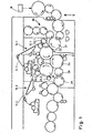
- a Filteransetzmaschine is shown schematically in a front view fragmentary schematically, wherein the Filteransetzmaschine via a drum assembly T for supplying tobacco sticks from a schematically drawn cigarette rod machine P tobacco sticks double the length of use receives.
- a cigarette rod machine is known under the name "PROTOS" of the patent applicant.
- the tobacco sticks double use length are cut and spread.
- the assembly drum 21 are transported over a further drum assembly M double-length filter plugs, which are inserted between two longitudinally spaced tobacco rods.
- the compiled articles 50, 60 are transferred from the assembly drum 21 to a conveyor drum 22 and fed to a pad apparatus 10.1 for the first group 50 of assembled tobacco rod filter plug tobacco rod groups.
- a coating apparatus is in the patent DE-C-39 18 137 described in detail, the content of which is fully incorporated into the content of the present application.
- a gluing paper strip 11.1 glued and conveyed in the dressing apparatus 10.1 is mounted on a cutting drum 12.1 of the knives of a cutterhead 13.1. cut into compound leaflets 40.1.
- the connecting leaflets 40.1 are attached to the articles of a first group 50 on the conveyor drum 22.
- the articles of the first (50) and second (60) groups are transported further, wherein the front end of the connecting leaflet 40.1. protrudes on the article 50.
- the articles 50, 60 are transported on to a folding star 23.1, which applies the front end of the connecting leaflets 40.1 to the articles 50.
- the articles 50, 60 are conveyed to a removal drum 24, wherein the removal drum 24 removes the articles 60 of the second group from the drum 22, which are not provided with a connecting blade.
- the removal drum 24 transfers the removed articles 60 of the second group to a conveyor drum 25, which transports the articles 60 to a coating apparatus 10.2, in which a tipping paper strip 11.2 is conveyed.
- the second coating apparatus 10.2 has a cutterhead 13.2 which cooperates with the tipping paper strip 11.2 with a cutting drum 12.2 cuts in connecting papers.
- the conveyor drum 25 conveys the articles 60 of the second group to a conveyor drum 26.
- the conveyor drum 26 at the same time picks up on the conveyor drum 22 further transported article 50 of the first group, so that the articles of the first (50) and the second (60) group alternately be placed on the drum.
- the articles of the first and second groups 50, 60 are conveyed to a roll block rolling device 27 so that the bonding leaflets are completely wrapped around the tobacco rod filler plug tobacco rod groups 50, 60.
- the finished wrapped articles 50, 60 are subsequently transferred to a conveyor drum 28 and a further conveyor drum 29 and provided for further processing processes on a filter attachment machine.
- filter cigarettes of simple useful length are subsequently produced from the double-length filter cigarettes.
- FIG. 2 is an embodiment of the conveyor drum 22 according to the prior art Fig. 1 shown in detail in a detail view.
- Article of a first and a second Group 50, 60 of cigarette filter plug-cigarette groups are conveyed by a compilation drum 21 in the direction of arrow to the removal drum 24.
- articles 50, 60 are transferred to the conveyor drum 22.
- the conveyor drum 22 has movable arms with receiving troughs for articles 50, 60, so that the distance between the alternately arranged articles 50, 60 is variable and a speed adjustment of the articles 50, 60 takes place at the speed of the cutting drum 12.1. This is achieved by slowing down the corresponding articles 50, 60 before the transfer of the connecting leaflet 40.1 from the cutting drum 12.1 to the articles 50, 60, so that in the transfer point of the connecting leaflet 40.1 to the articles 50 the connecting leaflet 40.1 and the respective article 50 have the same speed.
- connection papers 40.1 After the transfer of the connection papers 40.1 to the articles 50, the articles 50, 60 on the conveyor drum 22 are accelerated.
- the Hebelärmchen for the article 50 with connecting leaflet 40.1 have needle-shaped spacers 37 for the connection leaflet 40.1 to prevent sticking of the connection leaflet 40.1 with the Hebelärmchen.
- the front end of the connecting leaflets 40.1 is applied to the articles 50 by means of the folding star 23.1. While the articles 50 with their Verblndungsblättchen 40.1 on the drum 22 to the drum 26 (see. Fig. 1 ), the articles 60 of the second group, which have not yet been provided with a connecting lamina, are conveyed via the removal drum 24 to a conveying drum 25 (cf. Fig. 1 ).
- the deceleration and acceleration operations are carried out independently of the conveying speed of the drum 22 substantially in the area of the transfer of the connecting leaflet 40.1 to the articles 50, but also to adjust the speeds in receiving or dispensing the articles 50, 60 and the application of the connecting leaflet 40.1 to Articles 50.
- Fig. 3 shows an embodiment of a conveyor drum 22 (see. Fig. 2 ) according to the prior art in cutting.
- the conveying direction of in Fig. 3 shown arrangement is from right to left.
- Fig. 3 shows an arrangement of a first conveyor segment 51 with a rod-shaped article 50 and a second conveyor segment 61 with a rod-shaped article 60.
- the first conveyor segment 51 has one or more support pins 39, on which a connecting plate 40.1 rests.
- a further conveyor segment is arranged on the drum body 32 of the conveyor drum 22.
- the supporting segment 52 for the supporting needles 39 is mounted on the drum body 32 together with the conveying segment 51 for the first group of articles as a structural unit.
- the connecting leaflet 40.1 is applied to the articles 50 before the first covering device (cf. Fig. 1 ).
- the support pins 39 gluing the glued on the underside connecting leaflets 40.1 is avoided with the conveyor segment 50.
- the support pins 39 run ahead of the receptacles for the article 60 in the second conveyor segments.
- the articles 60 on the second conveyor segment 61 are conveyed on by a second covering device, on which the articles 60 (of the second group) are provided with a connecting lamina.
- the bearing surface of the connecting blades 40.1 on the support pins 39 is point-shaped, so that when the conveyor segments 61, 62 are movable relative to each other, the glue pattern on the connecting blades 40.1 is maintained.
- Fig. 4 is a perspective view of a conveyor segment 52 according to the prior art shown, wherein the conveyor segment 52 has on the top side by side arranged support pins 39 for the connecting plate.
- the conveyor segment 52 On the drum body of a conveyor drum (see. Fig. 3 Furthermore, bores 53 are introduced into the conveying segment 52, so that screws are screwed into the drum body via the bores 53.
- the fine support needles 39 form a kind of spacer means for a connection paper or a tipping paper leaflet, so that the underside of the tipping paper leaflet with its glue pattern does not adhere to the upper side of the conveying segment 52.
- the support pins 39 In order to arrange the support pins 39 on the conveyor segment 52, it is necessary for the production that first several holes are drilled at predetermined distances from each other in the conveying segment 52 on the top. Thereafter, the support pins 39 made of metal, in particular steel, are inserted into the drilled holes and fixed, for example, by means of an adhesive or the like in the respective hole.
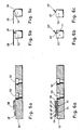
- FIGS. 7a and 8a respectively show longitudinal sections through a conveyor segment 52 according to the invention. Corresponding cross sections through the conveyor segments 52 of Fig. 5a and 6a are in the FIGS. 5b, 5c, 6b, 6c shown.
- Fig. 5a shows the conveyor segment 52 with a spacer strip 59 according to the invention, which projects beyond the top of the conveyor segment 52.
- the spacer bar 59 supports a connecting leaflet or wrap strip portion 58 so that the wrap strip 58 is supported at its free end spaced from the conveyor segment 52 across its width.
- the wrapping strip portion 58 preferably has a glue pattern on the underside so as to be connected to the articles by wrapping with a rod-shaped article or a rod-shaped smoking article group, for example in a rolling process.
- a rod-shaped article or a rod-shaped smoking article group for example in a rolling process.
- the wrapping strip portion 58 is shown spaced from the spacer bar 59.
- Fig. 5b shows a cross section through the conveyor segment 52 and the spacer bar 59. From this drawing shows that the spacer bar 59 is applied to the conveyor segment 52 and inserted into a groove-shaped recess accurately and then bonded to the conveyor segment 52.
- the spacer bar 59 and the conveyor segment 52 are made in one piece.
- the spacer bar 59 supports covering paper flakes or wrapping strip portions such that the spacer bar 59, as a one-piece component, supports a predetermined or the entire width of the envelope strip section 58 via a linear contact.
- FIG. 6a an embodiment of a spacer bar 59 is shown, wherein the spacer bar 59 has a plurality of teeth or tongue parts 69.
- the tongue portions 69 form a spacer bar 59 by means of which the jacket strip portion 58 is held over a predetermined width.
- Fig. 6a also shows that the spacer bar 59 is formed in several parts with multiple zones 69.
- the spacer strip 59 is composed of two strip bodies 71, 72, so that the overall result is a spacer strip 59 as a result of the multiple-row arrangement of a plurality of strip bodies 71, 72.
- Fig. 6b shows a cross section through the conveyor segment 52 (FIG. Fig. 6a ) and a strip body 71, wherein the strip body 71 is introduced or arranged with its tongue parts 69 in a recess or depression of the conveyor segment 52.
- Fig. 6c shows a non-inventive variation of the conveyor segment 52, wherein the tongue portions 69 are integrally formed together with the conveyor segment 52, resulting in a simplified handling and manufacture.
- the conveyor segment 52 and the spacer bar 59 are made as an injection molded part.
- the spacer bar 59 and the conveyor segment 52 are each made as an injection molded part and connected to each other.
- spacer bar 59 and the conveyor segment 52 are manufactured as milled components.
- FIGS. 7, 8 Further modifications of the spacer bar 59 are shown, wherein Fig. 7 a jagged spacer bar 79 shows while Fig. 8 represents a spacer bar with a corrugated structure.
- the spacer bar 59 is integrally formed over a predetermined width of a cover strip portion to be supported, depending on the structure of the spacer bar, a linear or point-like contact between the spacer bar and the envelope strip section to be supported or to be held connecting tab at the corresponding contact points.
Landscapes
- Manufacturing Of Cigar And Cigarette Tobacco (AREA)
- Specific Conveyance Elements (AREA)
Description
- Die Erfindung betrifft eine Abstandshaltereinrichtung einer Fördertrommel der Tabak verarbeitenden Industrie, die einen Umhüllungsstreifenabschnitt, insbesondere ein Belagpapierblättchen, über eine vorbestimmte Breite des Umhüllungsstreifenabschnitts abstützt, wobei die Abstandshaltereinrichtung als Abstandsleiste ausgebildet ist. Ferner betrifft die Erfindung eine Fördertrommel der Tabak verarbeitenden Industrie.
- In Filteransetzmaschinen werden zwischen geschnittene und längsaxial beabstandete Tabakstöcke jeweils ein Filter- bzw. Mundstück doppelter Länge eingelegt, wobei anschließend ein beleimtes Verbindungsblättchen oder Belagblättchen an eine Tabakstock-Mundstück-Tabakstock-Gruppe angeheftet wird. Hierbei wird das beleimte Verbindungsblättchen über eine Saugwalze einer Belageinrichtung der mit einem definierten, vorbestimmten Teilungsabstand bzw. queraxialen Abstand geförderten Tabakstock-Mundstück-Tabakstock-Gruppe zugeführt.
- In
EP-A-1 466 535 ist eine Filteransetzmaschine beschrieben, bei der auf einer Fördertrommel alternierend jede zweite Artikelgruppe mit Belagblättchen versehen wird und die jeweils andere Artikelgruppe einer zweiten Belagpapierzuführvorrichtung zugeführt wird. Die Fördertrommel ist als Ärmchentrommel mit Hebelsegmenten für jeweils einen Artikel ausgebildet, bei der die Hebelsegmente für diejenigen Artikel, die an einer ersten Belagpapierzuführeinrichtung mit einem Verbindungsblättchen versehen werden, Distanzhalter aufweisen, die ein Anheften der beleimten Verbindungsblättchen an die Oberfläche der Hebelsegmente verhindern. - In
EP-A-0 620 983 ist weiterhin ein Verfahren zur Herstellung von Filterzigaretten offenbart. Hierbei wird ein beleimter Belagpapierstreifen auf einer Belagwalze in Belagpapierstreifen geschnitten, die an Rauchartikelgruppen angeheftet werden, wobei das vorauseilende Ende des Belagpapierstreifens an einem Halteorgan angelegt wird. Das Halteorgan ist dabei in Gestalt einer Saugbohrung ausgebildet. - Überdies offenbart
FR-A-1 414 956 - Ausgehend von diesem Stand der Technik besteht die Aufgabe der vorliegenden Erfindung darin, die Fertigung von Fördertrommeln der Tabak verarbeitenden Industrie mit Distanzhaltern für Verbindungsblättchen zu vereinfachen, wobei es möglich sein soll, die Reinigung einer Fördertrommel zu erleichtern.
- Gelöst wird diese Aufgabe durch eine Abstandshaltereinrichtung einer Fördertrommel der Tabak verarbeitenden Industrie, die einen Umhüllungsstreifenabschnitt, insbesondere ein Belagpapierblättchen, über eine vorbestimmte Breite des Streifenabschnitts abstützt, wobei die Abstandshaltereinrichtung als Abstandsleiste ausgebildet ist, die dadurch weitergebildet wird, dass die Abstandsleiste auf einem Fördersegment der Fördertrommel ausgebildet ist, wobei die Abstandsleiste als Spritzgussteil ausgebildet ist und die Abstandsleiste als ein Bauteil auf dem Fördersegment angeordnet wird oder ist.
- Gemäß dem Stand der Technik sind zur Abstützung eines Belagpapierblättchens auf einer Belagpapiertrommel mehrere nebeneinander angeordnete Nadeln vorgesehen, wobei auf einem Segmentkörper zunächst Löcher gebohrt werden müssen, um die Nadeln, die in Kontakt mit dem Belagpapierblättchen gelangen und das Blättchen halten, anschließend einsetzen zu können. Die Anfertigung derartiger Segmente mit Abstandsnadeln bedarf einer hohen Genauigkeit und ist sehr zeitaufwändig. Darüber hinaus ist eine Reparatur einer abgebrochenen Abstandsnadel bzw. eines Distanzhalters sehr aufwändig.
- Demgegenüber beruht die Erfindung auf dem Gedanken, dass die Abstandsleiste beispielsweise einstückig ausgebildet ist, so dass ein Umhüllungsstreifenabschnitt für einen Rauchartikel der Tabak verarbeitenden Industrie über die Breite des Streifenabschnittes gehalten wird. Durch die einstückige Ausbildung als Abstandsleiste wird die Fertigung von Fördertrommeln, beispielsweise einer Belagpapiertrommel wesentlich erleichtert, da einerseits die Fertigung von Abstandselementen bzw. Abstandssegmenten im Herstellungsprozess vereinfacht wird. Darüber hinaus wird die Reinigung einer Fördertrommel mit derartigen Abstandssegmenten bzw. Abstandsleisten verbessert, da sich weniger Leim an der Kontaktfläche der beleimten Belagpapierblättchen absetzt. Außerdem können ggf. die Reinigungsbürsten für eine Belagpapiertrommel an einer Filteransetzmaschine entfallen.
- Gemäß einer bevorzugten Ausführungsform ist vorgesehen, dass bei Kontakt der Abstandsleiste mit dem Umhüllungsstreifenabschnitt die Kontaktfläche kontinuierlich oder unterbrochen über die Breite des Streifenabschnittes ausgebildet ist. Durch eine kontinuierliche Kontaktfläche oder -linie wird der Streifenabschnitt zuverlässig abgestützt. Bei einer unterbrochenen Kontaktlinie bleibt weniger Leim an den Kontaktflächen haften.
- Dazu ist weiter vorgesehen, dass der Kontakt der Abstandsleiste mit den Umhüllstreifenabschnitten linienförmig und/oder punktförmig ausgebildet ist.
- Insbesondere ist der Kontakt zwischen der Abstandsleiste und dem Umhüllungsstreifenabschnitt geradlinig ausgebildet.
- Gemäß einer bevorzugten Weiterbildung sind mehrere Kontakte bzw. Kontaktflächen zwischen der Abstandsleiste und dem Umhüllungsstreifenabschnitt über die Breite des Abschnittes ausgebildet, wodurch eine gute Abstützung des Umhüllungsstreifenabschnittes erfolgt.
- Darüber hinaus ist die Abstandsleiste in einer bevorzugten Ausführungsform einstückig oder mehrteilig ausgebildet, wobei beispielsweise ein Teil einer mehrteiligen Abstandsleiste den beleimten Umhüllungsstreifenabschnitt über eine vorbestimmte Breite abstützt.
- Ferner sind vorzugsweise das Fördersegment und die Abstandsleiste einstückig ausgebildet. Dadurch wird eine einfache Handhabung der Abstandsleiste auf dem Trommelkörper einer Fördertrommel erreicht.
- Eine einfache Fertigung ergibt sich ferner dadurch, dass die Abstandsleiste und/oder das Fördersegment als Spritzgussteil oder Spritzgussteile ausgebildet sind.
- Weiterhin ist es gemäß einer Ausführungsform möglich, dass die Abstandsleiste und/oder die Fördersegmente als gefräste Teile ausgebildet sind.
- Insbesondere ist die Fördertrommel, auf der die Abstandsleiste angeordnet wird oder ist, als Taumeltrommel oder Belagpapiertrommel ausgebildet.
- Gelöst wird ferner die Aufgabe durch eine Fördertrommel der Tabak verarbeitenden Industrie, die mit einer Abstandshaltereinrichtung bzw. einer erfindungsgemäßen Abstandsleiste, wie sie voranstehend beschrieben ist, ausgestattet ist.
- Die Erfindung wird nachstehend ohne Beschränkung des allgemeinen Erfindungsgedankens anhand von Ausführungsbeispielen unter Bezugnahme auf die Zeichnungen beschrieben, wobei bezüglich aller im Text nicht näher erläuterten erfindungsgemäßen Einzelheiten ausdrücklich auf die Zeichnungen verwiesen wird. Es zeigen:
- Fig. 1
- eine bekannte Filteransetzmaschine mit zwei Belagpapieraggregaten in einer schematischen Vorderansicht im Ausschnitt;
- Fig. 2
- eine Detaildarstellung einer Trommelanordnung aus
Fig. 2 ; - Fig.3
- einen schematischen Ausschnitt einer Fördertrommel aus
Fig. 2 ; - Fig. 4
- eine perspektivische Ansicht eines Fördersegments einer Fördertrommel gemäß dem Stand der Technik;
- Fig. 5a, 5b, 5c
- verschiedene Ansichten eines erfindungsgemäßen Fördersegments einer Fördertrommel;
- Fig. 6a, 6b, 6c
- verschiedene Ansichten eines weiteren Fördersegments einer Fördertrommel;
- Fig.7
- einen Längsschnitt durch ein weiteres Ausführungsbeispiel eines Fördersegments und
- Fig. 8
- einen Längsschnitt durch ein weiteres Ausführungsbeispiel eines Fördersegments.
- In den folgenden Figuren sind jeweils gleiche oder gleichartige Elemente bzw. entsprechende Teile mit denselben Bezugsziffern versehen, so dass von einer entsprechenden erneuten Vorstellung abgesehen wird.
- In
Fig. 1 ist eine Filteransetzmaschine in einer Vorderansicht ausschnittsweise schematisch dargestellt, wobei die Filteransetzmaschine über eine Trommelanordnung T zur Zuführung von Tabakstöcken von einer schematisch eingezeichneten Zigarettenstrangmaschine P Tabakstöcke doppelter Gebrauchslänge empfängt. Eine Zigarettenstrangmaschine ist unter der Bezeichnung "PROTOS" der Patentanmelderin bekannt. - Auf ihrem Förderweg zu einer Zusammenstelltrommel 21 werden die Tabakstöcke doppelter Gebrauchslänge geschnitten und gespreizt. Auf der Zusammenstelltrommel 21 werden über eine weitere Trommelanordnung M doppeltlange Filterstopfen transportiert, die jeweils zwischen zwei längsaxial beabstandete Tabakstöcke eingefügt werden. Hierdurch wird auf der Zusammenstelltrommel 21 eine Folge von queraxial hintereinander angeordneten Tabakstock-Filterstopfen-Tabakstock-Gruppen gebildet.
- Die zusammengestellten Artikel 50, 60 (siehe
Fig. 2 ) werden von der Zusammenstelltrommel 21 an eine Fördertrommel 22 übergeben und einem Belagapparat 10.1 für die erste Gruppe 50 zusammengestellter Tabakstock-Filterstopfen-Tabakstock-Gruppen zugeführt. Ein Belagapparat ist in der PatentschriftDE-C-39 18 137 ausführlich beschrieben, deren Inhalt vollumfänglich in den Inhalt der vorliegenden Anmeldung aufgenommen wird. - Ein im Belagapparat 10.1 beleimter und geförderter Belagpapierstreifen 11.1 wird auf einer Schneidtrommel 12.1 von den Messern einer Messertrommel 13.1. in Verbindungsblättchen 40.1 geschnitten. Die Verbindungsblättchen 40.1 werden an die Artikel einer ersten Gruppe 50 auf der Fördertrommel 22 angeheftet.
- Nach dem Anheften der Verbindungsblättchen 40.1 an die Artikel 50 der ersten Gruppe werden die Artikel der ersten (50) und der zweiten (60) Gruppe weitertransportiert, wobei das vordere Ende des Verbindungsblättchens 40.1. an dem Artikel 50 absteht. Die Artikel 50, 60 werden zu einem Faltstern 23.1 weitertransportiert, der das vordere Ende der Verbindungsblättchen 40.1 an die Artikel 50 anlegt. Nachfolgend werden die Artikel 50, 60 zu einer Entnahmetrommel 24 gefördert, wobei die Entnahmetrommel 24 die Artikel 60 der zweiten Gruppe von der Trommel 22 entnimmt, die nicht mit einem Verbindungsblättchen versehen sind.
- Die Entnahmetrommel 24 übergibt die entnommenen Artikel 60 der zweiten Gruppe an einer Fördertrommel 25, die die Artikel 60 zu einem Belagapparat 10.2 transportiert, in dem ein Belagpapierstreifen 11.2 gefördert wird. Der zweite Belagapparat 10.2 verfügt über eine Messertrommel 13.2, die den Belagpapierstreifen 11.2 in Zusammenwirken mit einer Schneidtrommel 12.2 in Verbindungsblättchen schneidet.
- Die vom Belagpapierstreifen 11.2 abgeschnittenen Verbindungsblättchen werden an die Tabakartikel bzw. Tabakstock-Filterstopfen-Tabakstock-Gruppen 60 übergeben und angeheftet. Das vordere Ende des Verbindungsblättchens wird danach mittels eines Faltsterns 23.2 an den Artikeln 60 auf der Fördertrommel 25 angelegt. In diesem Zusammenhang wird ausdrücklich auf die
europäische Patentanmeldung EP-A-1 466 535 verwiesen, in der dieser Vorgang dargestellt und beschrieben ist. - Die Fördertrommel 25 fördert die Artikel 60 der zweiten Gruppe zu einer Fördertrommel 26. Die Fördertrommel 26 nimmt gleichzeitig die auf der Fördertrommel 22 weitertransportierten Artikel 50 der ersten Gruppe auf, so dass die Artikel der ersten (50) und der zweiten (60) Gruppe alternierend auf der Trommel angeordnet werden.
- Nachfolgend werden die Artikel der ersten und der zweiten Gruppen 50, 60 zu einer Rolleinrichtung 27 mit einem Rollklotz transportiert, so dass die Verbindungsblättchen vollständig um die Tabakstock-Fliterstopfen-Tabakstock-Gruppen 50, 60 herumgewickelt werden. Die fertig umwickelten Artikel 50, 60 werden nachfolgend an eine Fördertrommel 28 und eine weitere Fördertrommel 29 übergeben und für weitere Bearbeitungsprozesse an einer Filteransetzmaschine bereitgestellt. Insbesondere werden aus den doppeltlangen Filterzigaretten nachfolgend Filterzigaretten einfacher Gebrauchslänge hergestellt.
- In
Fig. 2 ist ein Ausführungsbeispiel der Fördertrommel 22 gemäß dem Stand der Technik ausFig. 1 in einer Detailansicht ausschnittsweise dargestellt. Artikel einer ersten und einer zweiten Gruppe 50, 60 von Zigaretten-Filterstopfen-Zigaretten-Gruppen werden von einer Zusammenstelltrommel 21 in Pfeilrichtung zur Entnahmetrommel 24 gefördert. - Von der Zusammenstelltrommel 21 werden Artikel 50, 60 an die Fördertrommel 22 übergeben. Die Fördertrommel 22 verfügt über bewegliche Ärmchen mit Aufnahmemulden für Artikel 50, 60, so dass der Abstand zwischen den alternierend angeordneten Artikeln 50, 60 veränderbar ist und eine Geschwindigkeitsanpassung der Artikel 50, 60 an die Geschwindigkeit der Schneidtrommel 12.1 stattfindet. Dies wird dadurch erreicht, dass vor der Übergabe des Verbindungsblättchens 40.1 von der Schneidtrommel 12.1 an die Artikel 50, 60 die entsprechenden Artikel 50, 60 verlangsamt werden, so dass im Übergabepunkt des Verbindungsblättchens 40.1 an die Artikel 50 das Verbindungsblättchen 40.1 und der jeweilige Artikel 50 die gleiche Geschwindigkeit haben.
- Nach der Übergabe der Verbindungsblättchen 40.1 an die Artikel 50 werden die Artikel 50, 60 auf der Fördertrommel 22 beschleunigt. Die Hebelärmchen für die Artikel 50 mit Verbindungsblättchen 40.1 weisen nadelförmige Distanzhalter 37 für die Verbindungsblättchen 40.1 auf, um ein Verkleben der Verbindungsblättchen 40.1 mit den Hebelärmchen zu verhindern.
- Im Anschluss an die Beschleunigung wird das vordere Ende der Verbindungsblättchen 40.1 an die Artikel 50 mittels des Faltsterns 23.1 angelegt. Während die Artikel 50 mit ihren Verblndungsblättchen 40.1 auf der Trommel 22 zu der Trommel 26 (vgl.
Fig. 1 ) transportiert werden, werden die noch nicht mit einem Verbindungsblättchen versehenen Artikel 60 der zweiten Gruppe über die Entnahmetrommel 24 zu einer Fördertrommel 25 (vgl.Fig. 1 ) gefördert. - Die Abbrems- und Beschleunigungsvorgänge werden unabhängig von der Fördergeschwindigkeit der Trommel 22 im Wesentlichen im Bereich der Übergabe des Verbindungsblättchens 40.1 an die Artikel 50 ausgeführt, jedoch auch zur Anpassung der Geschwindigkeiten bei der Aufnahme bzw. Abgabe der Artikel 50, 60 und dem Anlegen des Verbindungsblättchens 40.1 an die Artikel 50 ausgeführt.
- Durch die Veränderung des Abstands zwischen den Artikeln 50 der ersten Gruppe und den Artikeln 60 der zweiten Gruppe wird außerdem ein ausreichender Abstand geschaffen, so dass die Verbindungsblättchen 40.1 vom ersten Belagapparat 10.1 an die Artikel 50 angelegt werden, ohne dass die Verbindungsblättchen 40.1 die Artikel der anderen Gruppe 60 berühren.
-
Fig. 3 zeigt eine Ausführungsform einer Fördertrommel 22 (vgl.Fig. 2 ) gemäß dem Stand der Technik im Ausschnitt. Die Förderrichtung der inFig. 3 gezeigten Anordnung ist von rechts nach links. -
Fig. 3 zeigt eine Anordnung aus einem ersten Fördersegment 51 mit einem stabförmigen Artikel 50 sowie einem zweiten Fördersegment 61 mit einem stabförmigen Artikel 60. Das erste Fördersegment 51 weist eine bzw. mehrere Stütznadeln 39 auf, auf dem ein Verbindungsblättchen 40.1 aufliegt. - Zwischen dem Fördersegment 51 und dem Fördersegment 61 ist ein weiteres Fördersegment auf dem Trommelkörper 32 der Fördertrommel 22 angeordnet. Das Fördersegment 52 für die Stütznadeln 39 ist zusammen mit dem Fördersegment 51 für die erste Artikelgruppe als eine Baueinheit auf dem Trommelkörper 32 befestigt.
- Das Verbindungsblättchen 40.1 ist vor der ersten Belageinrichtung an die Artikel 50 aufgebracht (vgl.
Fig. 1 ). Durch die Stütznadeln 39 wird ein Verkleben der auf der Unterseite beleimten Verbindungsblättchen 40.1 mit dem Fördersegment 50 vermieden. Die Stütznadeln 39 laufen den Aufnahmen für die Artikel 60 in den zweiten Fördersegmenten voraus. Die Artikel 60 auf dem zweiten Fördersegment 61 werden von einer zweiten Belageinrichtung weitergefördert, an der die Artikel 60 (der zweiten Gruppe) mit einem Verbindungsblättchen versehen werden. - Die Auflagefläche der Verbindungsblättchen 40.1 auf den Stütznadeln 39 ist punktförmig, so dass bei gegeneinander beweglichen Fördersegmenten 61, 62 das Leimbild auf den Verbindungsblättchen 40.1 erhalten bleibt.
- In
Fig. 4 ist eine perspektivische Darstellung eines Fördersegments 52 gemäß dem Stand der Technik dargestellt, wobei das Fördersegment 52 auf der Oberseite nebeneinander angeordnete Stütznadeln 39 für das Verbindungsblättchen aufweist. Um das Fördersegment 52 auf dem Trommelkörper einer Fördertrommel (vgl.Fig. 3 , Bezugszeichen 22) zu befestigen, sind ferner Bohrungen 53 in das Fördersegment 52 eingebracht, so dass über die Bohrungen 53 Schrauben in den Trommelkörper eingeschraubt werden. - Die feinen Stütznadeln 39 bilden eine Art Abstandshaltereinrichtung für ein Verbindungsblättchen bzw. ein Belagpapierblättchen, so dass die Unterseite des Belagpapierblättchens mit dessen Leimbild nicht auf die Oberseite des Fördersegments 52 anhaftet.
- Um die Stütznadeln 39 auf dem Fördersegment 52 anzuordnen, ist es für die Herstellung erforderlich, dass zunächst mehrere Löcher in vorbestimmten Abständen zueinander in das Fördersegment 52 auf der Oberseite gebohrt werden. Danach werden die Stütznadeln 39 aus Metall, insbesondere Stahl, in die gebohrten Löcher eingesetzt und beispielsweise mittels eines Klebers oder dergleichen im jeweiligen Loch befestigt.
- In den
Figuren 5a, 6a , 7a und 8a sind jeweils Längsschnitte durch ein erfindungsgemäßes Fördersegment 52 gezeigt. Entsprechende Querschnitte durch die Fördersegmente 52 vonFig. 5a und 6a sind in denFiguren 5b, 5c, 6b, 6c dargestellt. -
Fig. 5a zeigt das Fördersegment 52 mit einer erfindungsgemäßen Abstandsleiste 59, die die Oberseite des Fördersegments 52 überragt. Die Abstandsleiste 59 stützt ein Verbindungsblättchen oder einen Umhüllungsstreifenabschnitt 58, so dass der Umhüllungsstreifen 58 mit seinem freien Ende beabstandet zu dem Fördersegment 52 über seine Breite abgestützt wird. - Der Umhüllungsstreifenabschnitt 58 weist auf der Unterseite vorzugsweise ein Leimbild auf, um durch Umwicklung mit einem stabförmigen Artikel oder einer stabförmigen Rauchartikelgruppe mit den Artikeln verbunden zu werden, beispielsweise in einem Rollvorgang. Aus Gründen der besseren Darstellbarkeit ist in den
Figuren 5a, 5b und 5c der Umhüllungsstreifenabschnitt 58 beabstandet zu der Abstandsleiste 59 eingezeichnet. -
Fig. 5b zeigt einen Querschnitt durch das Fördersegment 52 und die Abstandsleiste 59. Aus dieser Zeichnung geht hervor, dass die Abstandsleiste 59 auf das Fördersegment 52 aufgebracht wird bzw. in eine nutförmige Vertiefung passgenau eingesetzt und anschließend mit dem Fördersegment 52 verklebt wird. - In dem nicht erfindungsgemäßen Ausführungsbeispiel bzw. dem Querschnitt gemäß
Fig. 5c ist gezeigt, dass die Abstandsleiste 59 und das Fördersegment 52 aus einem Stück hergestellt sind. Bei dem funktionsgerechten Einsatz des Fördersegmentes 52 auf einer Fördertrommel stützt die Abstandsleiste 59 Belagpapierblättchen bzw. Umhüllungsstreifenabschnltte derart ab, dass die Abstandsleiste 59 als einstückiges Bauteil eine vorbestimmte oder die gesamte Breite des Umhüllungsstreifenabschnittes 58 über einen linienförmigen Kontakt abstützt. - Bei dem Ausführungsbeispiel gemäß
Fig. 6a ist eine Ausführungsform einer Abstandsleiste 59 dargestellt, wobei die Abstandsleiste 59 mehrere Zähne oder Zungenteile 69 aufweist. Die Zungenteile 69 bilden eine Abstandsleiste 59, mittels der der Umhüllungsstreifenabschnitt 58 über eine vorbestimmte Breite gehalten wird. - Aus
Fig. 6a geht ferner hervor, dass die Abstandsleiste 59 mehrteilig mit mehreren Zonen 69 ausgebildet ist. Hierbei setzt sich die Abstandsleiste 59 aus zwei Leistenkörpern 71, 72 zusammen, so dass durch die mehrtellige Aneinanderreihung mehrerer Leistenkörper 71, 72 sich insgesamt eine Abstandsleiste 59 ergibt. -
Fig. 6b zeigt einen Querschnitt durch das Fördersegment 52 (Fig. 6a ) und einen Leistenkörper 71, wobei der Leistenkörper 71 mit seinen Zungenteilen 69 in eine Ausnehmung oder Vertiefung des Fördersegments 52 eingebracht bzw. angeordnet wird. -
Fig. 6c zeigt eine nicht erfindungsgemäße Variation des Fördersegments 52, wobei die Zungenteile 69 zusammen mit dem Fördersegment 52 einteilig ausgebildet sind, wodurch sich eine vereinfachte Handhabung und Herstellung ergibt. Beispielsweise sind das Fördersegment 52 und die Abstandsleiste 59 als ein Spritzgussteil hergestellt. Alternativ sind die Abstandsleiste 59 und das Fördersegment 52 jeweils als Spritzgussteil hergestellt und miteinander verbunden. - Darüber hinaus können die Abstandsleiste 59 und das Fördersegment 52 als gefräste Bauteile gefertigt werden.
- In den
Figuren 7, 8 sind weitere Modifikationen der Abstandsleiste 59 gezeigt, wobeiFig. 7 eine gezackte Abstandsleiste 79 zeigt, währendFig. 8 eine Abstandsleiste mit einer gewellten Struktur darstellt. - Dadurch, dass die Abstandsleiste 59 über eine vorbestimmte Breite eines abzustützenden Umhüllungsstreifenabschnitts einstückig ausgebildet ist, wird in Abhängigkeit der Struktur der Abstandsleiste ein linienförmiger oder punktförmiger Kontakt zwischen der Abstandsleiste und dem abzustützenden Umhüllungsstreifenabschnitt bzw. des zu haltenden Verbindungsblättchens an den entsprechenden Kontaktstellen hergestellt.
-
- 10.1, 10.2
- Belagapparat
- 11.1, 11.2
- Belagpapierstreifen
- 12.1, 12.2
- Schneidtrommel
- 13.1, 13.2
- Messertrommel
- 21
- Zusammenstelltrommel
- 22
- Fördertrommel
- 23.1, 23.2
- Faltstern
- 24
- Entnahmetrommel
- 25
- Fördertrommel
- 26
- Fördertrommel
- 27
- Rolleinrichtung
- 28
- Fördertrommel
- 29
- Fördertrommel
- 32
- Trommelkörper
- 37
- Distanzhalter
- 38
- Haltesegment
- 39
- Stütznadel
- 40.1
- Verbindungsblättchen
- 50
- Artikel
- 51
- Fördersegment
- 52
- Fördersegment
- 53
- Bohrung
- 58
- Umhüllungsstreifenabschnitt
- 59
- Abstandsleiste
- 60
- Artikel
- 61
- Fördersegment
- 69
- Zungenteile
- 71
- Leistenkörper
- 72
- Leistenkörper
- T
- Trommelanordnung (Tabakstöcke)
- P
- Zigarettenstrangmaschine
- M
- Trommelanordnung (Filterstöcke)
Claims (9)
- Abstandshaltereinrichtung (39, 59) einer Fördertrommel (22) der Tabak verarbeitenden Industrie, die einen Umhüllungsstreifenabschnitt (40.1, 58), insbesondere ein Belagpapierblättchen, über eine vorbestimmte Breite des Umhüllungsstreifenabschnitts (40.1, 58) abstützt, wobei die Abstandshaltereinrichtung (59) als Abstandsleiste (59) ausgebildet ist, dadurch gekennzeichnet, dass die Abstandsleiste (59) auf einem Fördersegment (52) der Fördertrommel (22) ausgebildet ist, wobei die Abstandsleiste (59) als Spritzgussteil ausgebildet ist und die Abstandsleiste (59) als ein Bauteil auf dem Fördersegment (52) angeordnet ist oder wird.
- Abstandshaltereinrichtung (39, 59) nach Anspruch 1, dadurch gekennzeichnet, dass bei Kontakt der Abstandsleiste (59) mit dem Umhüllungsstreifenabschnitt (40.1, 58) die Kontaktfläche kontinuierlich oder unterbrochen über die Breite ausgebildet ist.
- Abstandshaltereinrichtung (39, 59) nach Anspruch 1 oder 2, dadurch gekennzeichnet, dass der Kontakt der Abstandsleiste (59) und dem Umhüllungsstreifenabschnitt (40.1, 58) linienförmig und/oder punktförmig ausgebildet ist.
- Abstandshaltereinrichtung (39, 59) nach Anspruch 3, dadurch gekennzeichnet, dass der Kontakt geradlinig ausgebildet ist.
- Abstandshaltereinrichtung (39, 59) nach einem der Ansprüche 1 bis 4, dadurch gekennzeichnet, dass mehrere Kontakte zwischen der Abstandsleiste (59) und dem Umhüllungsstreifenabschnitt (40.1, 58) ausgebildet sind.
- Abstandshaltereinrichtung (39, 59) nach einem der Ansprüche 1 bis 5, dadurch gekennzeichnet, dass die Abstandsleiste (59) einstückig oder mehrteilig ausgebildet ist.
- Abstandshaltereinrichtung (39, 59) nach einem der Ansprüche 1 bis 6, dadurch gekennzeichnet, dass die Abstandsleiste (59) und/oder die Fördersegmente (52) als gefräste Teile ausgebildet sind.
- Abstandshaltereinrichtung (39, 59) nach einem der Ansprüche 1 bis 7, dadurch gekennzeichnet, dass die Fördertrommel (22) als Taumeltrommel oder Belagpapiertrommel ausgebildet ist.
- Fördertrommel der Tabak verarbeitenden Industrie mit einer Abstandshaltereinrichtung (39, 59) nach einem der Ansprüche 1 bis 8.
Priority Applications (1)
| Application Number | Priority Date | Filing Date | Title |
|---|---|---|---|
| PL07007976T PL1849371T3 (pl) | 2006-04-24 | 2007-04-19 | Element dystansowy bębna transportowego w przemyśle tytoniowym |
Applications Claiming Priority (1)
| Application Number | Priority Date | Filing Date | Title |
|---|---|---|---|
| DE102006019329A DE102006019329A1 (de) | 2006-04-24 | 2006-04-24 | Abstandshalter einer Fördertrommel der Tabak verarbeitenden Industrie |
Publications (2)
| Publication Number | Publication Date |
|---|---|
| EP1849371A1 EP1849371A1 (de) | 2007-10-31 |
| EP1849371B1 true EP1849371B1 (de) | 2012-03-14 |
Family
ID=38289018
Family Applications (1)
| Application Number | Title | Priority Date | Filing Date |
|---|---|---|---|
| EP07007976A Not-in-force EP1849371B1 (de) | 2006-04-24 | 2007-04-19 | Abstandhalter einer Fördertrommel der Tabak verarbeitenden Industrie |
Country Status (5)
| Country | Link |
|---|---|
| EP (1) | EP1849371B1 (de) |
| CN (1) | CN101061891B (de) |
| AT (1) | ATE548924T1 (de) |
| DE (1) | DE102006019329A1 (de) |
| PL (1) | PL1849371T3 (de) |
Family Cites Families (8)
| Publication number | Priority date | Publication date | Assignee | Title |
|---|---|---|---|---|
| FR1414956A (fr) | 1964-08-04 | 1965-10-22 | Tabak & Ind Masch | Dispositif pour enrouler une petite feuille de liaison autour de groupes formés de préférence par une embouchure double de cigarette et deux cigarettes |
| US4745932A (en) * | 1985-07-10 | 1988-05-24 | G.D. Societa Per Azioni | Filter assembly machine |
| IT1200229B (it) * | 1986-10-17 | 1989-01-05 | Gd Spa | Macchina mettifiltro |
| IT1207721B (it) * | 1987-06-08 | 1989-05-25 | Gd Spa | Macchina mettifiltro |
| IT1229428B (it) * | 1988-06-11 | 1991-08-08 | Hauni Werke Koerber & Co Kg | Dispositivo di taglio. |
| IT1266304B1 (it) | 1993-04-23 | 1996-12-27 | Gd Spa | Metodo per la realizzazione di sigarette col filtro |
| ES2262920T3 (es) * | 2003-04-11 | 2006-12-01 | Hauni Maschinenbau Ag | Procedimiento para la union de componentes de articulos de fumador. |
| DE102005019682A1 (de) * | 2005-04-26 | 2006-11-09 | Hauni Maschinenbau Ag | Fördertrommel der Tabak verarbeitenden Industrie |
-
2006
- 2006-04-24 DE DE102006019329A patent/DE102006019329A1/de not_active Withdrawn
-
2007
- 2007-04-19 AT AT07007976T patent/ATE548924T1/de active
- 2007-04-19 EP EP07007976A patent/EP1849371B1/de not_active Not-in-force
- 2007-04-19 PL PL07007976T patent/PL1849371T3/pl unknown
- 2007-04-24 CN CN2007101026390A patent/CN101061891B/zh not_active Expired - Fee Related
Also Published As
| Publication number | Publication date |
|---|---|
| PL1849371T3 (pl) | 2012-08-31 |
| DE102006019329A1 (de) | 2007-10-25 |
| ATE548924T1 (de) | 2012-03-15 |
| CN101061891B (zh) | 2010-06-23 |
| EP1849371A1 (de) | 2007-10-31 |
| CN101061891A (zh) | 2007-10-31 |
Similar Documents
| Publication | Publication Date | Title |
|---|---|---|
| EP3259999B1 (de) | Förderung von stabförmigen artikeln der tabak verarbeitenden industrie | |
| EP2363029A1 (de) | Fördertrommel der Tabak verarbeitenden Industrie | |
| EP2661971B1 (de) | Herstellung von Filterzigaretten | |
| EP1595463B1 (de) | Fördertrommel für stabförmige Artikel der Tabak verarbeitenden Industrie | |
| EP3536172A2 (de) | Schiebetrommel der tabak verarbeitenden industrie | |
| EP1638419A1 (de) | Doppelbahnige filteransetzmaschine und herstellung von filterzigaretten | |
| EP3434117B1 (de) | Herstellung von stabförmigen rauchprodukten | |
| DE3201859A1 (de) | Verfahren und vorrichtung zum verbinden von stabfoermigen artikeln der tabakverarbeitenden industrie mittels eines verbindungsstreifens | |
| DE102016114641A1 (de) | Fördertrommel der Tabak verarbeitenden Industrie | |
| DE102012213337B4 (de) | Verfahren und Vorrichtung zum Herstellen eines Multisegmentfilterstrangs der Tabak verarbeitenden Industrie | |
| EP1897454B1 (de) | V-förmige Anordnung von Saugöffnungen | |
| EP1493341B1 (de) | Doppelbahnige Filteransetzmaschine | |
| DE102011007430B4 (de) | Förderung von stabförmigen Artikeln der Tabak verarbeitenden Industrie | |
| EP2532257B1 (de) | Fördertrommel der Tabak verarbeitenden Industrie | |
| DE102005012810A1 (de) | Verfahren zur Herstellung von Filterzigaretten | |
| EP2696707B1 (de) | Förderung von stabförmigen artikeln der tabak verarbeitenden industrie | |
| EP1849371A1 (de) | Abstandhalter einer Fördertrommel der Tabak verarbeitenden Industrie | |
| EP2604131A1 (de) | Betrieb einer Filteransetzmaschine | |
| EP1475002B1 (de) | Filteransetzmaschine mit doppelter Belagpapierzufuhr | |
| DE102005019682A1 (de) | Fördertrommel der Tabak verarbeitenden Industrie | |
| DE102006001445A1 (de) | Fördern von stabförmigen Artikeln der Tabak verarbeitenden Industrie | |
| DE102004035063A1 (de) | Abstandslose Verbindungsblättchen |
Legal Events
| Date | Code | Title | Description |
|---|---|---|---|
| PUAI | Public reference made under article 153(3) epc to a published international application that has entered the european phase |
Free format text: ORIGINAL CODE: 0009012 |
|
| AK | Designated contracting states |
Kind code of ref document: A1 Designated state(s): AT BE BG CH CY CZ DE DK EE ES FI FR GB GR HU IE IS IT LI LT LU LV MC MT NL PL PT RO SE SI SK TR |
|
| AX | Request for extension of the european patent |
Extension state: AL BA HR MK YU |
|
| 17P | Request for examination filed |
Effective date: 20080327 |
|
| 17Q | First examination report despatched |
Effective date: 20080509 |
|
| AKX | Designation fees paid |
Designated state(s): AT BE BG CH CY CZ DE DK EE ES FI FR GB GR HU IE IS IT LI LT LU LV MC MT NL PL PT RO SE SI SK TR |
|
| GRAP | Despatch of communication of intention to grant a patent |
Free format text: ORIGINAL CODE: EPIDOSNIGR1 |
|
| GRAS | Grant fee paid |
Free format text: ORIGINAL CODE: EPIDOSNIGR3 |
|
| GRAA | (expected) grant |
Free format text: ORIGINAL CODE: 0009210 |
|
| AK | Designated contracting states |
Kind code of ref document: B1 Designated state(s): AT BE BG CH CY CZ DE DK EE ES FI FR GB GR HU IE IS IT LI LT LU LV MC MT NL PL PT RO SE SI SK TR |
|
| REG | Reference to a national code |
Ref country code: GB Ref legal event code: FG4D Free format text: NOT ENGLISH |
|
| REG | Reference to a national code |
Ref country code: CH Ref legal event code: EP Ref country code: AT Ref legal event code: REF Ref document number: 548924 Country of ref document: AT Kind code of ref document: T Effective date: 20120315 |
|
| REG | Reference to a national code |
Ref country code: IE Ref legal event code: FG4D Free format text: LANGUAGE OF EP DOCUMENT: GERMAN |
|
| REG | Reference to a national code |
Ref country code: DE Ref legal event code: R096 Ref document number: 502007009450 Country of ref document: DE Effective date: 20120510 |
|
| REG | Reference to a national code |
Ref country code: NL Ref legal event code: T3 |
|
| PG25 | Lapsed in a contracting state [announced via postgrant information from national office to epo] |
Ref country code: LT Free format text: LAPSE BECAUSE OF FAILURE TO SUBMIT A TRANSLATION OF THE DESCRIPTION OR TO PAY THE FEE WITHIN THE PRESCRIBED TIME-LIMIT Effective date: 20120314 |
|
| LTIE | Lt: invalidation of european patent or patent extension |
Effective date: 20120314 |
|
| PG25 | Lapsed in a contracting state [announced via postgrant information from national office to epo] |
Ref country code: FI Free format text: LAPSE BECAUSE OF FAILURE TO SUBMIT A TRANSLATION OF THE DESCRIPTION OR TO PAY THE FEE WITHIN THE PRESCRIBED TIME-LIMIT Effective date: 20120314 Ref country code: LV Free format text: LAPSE BECAUSE OF FAILURE TO SUBMIT A TRANSLATION OF THE DESCRIPTION OR TO PAY THE FEE WITHIN THE PRESCRIBED TIME-LIMIT Effective date: 20120314 Ref country code: GR Free format text: LAPSE BECAUSE OF FAILURE TO SUBMIT A TRANSLATION OF THE DESCRIPTION OR TO PAY THE FEE WITHIN THE PRESCRIBED TIME-LIMIT Effective date: 20120615 |
|
| REG | Reference to a national code |
Ref country code: PL Ref legal event code: T3 |
|
| PG25 | Lapsed in a contracting state [announced via postgrant information from national office to epo] |
Ref country code: CY Free format text: LAPSE BECAUSE OF FAILURE TO SUBMIT A TRANSLATION OF THE DESCRIPTION OR TO PAY THE FEE WITHIN THE PRESCRIBED TIME-LIMIT Effective date: 20120314 |
|
| BERE | Be: lapsed |
Owner name: HAUNI MASCHINENBAU A.G. Effective date: 20120430 |
|
| PG25 | Lapsed in a contracting state [announced via postgrant information from national office to epo] |
Ref country code: CZ Free format text: LAPSE BECAUSE OF FAILURE TO SUBMIT A TRANSLATION OF THE DESCRIPTION OR TO PAY THE FEE WITHIN THE PRESCRIBED TIME-LIMIT Effective date: 20120314 Ref country code: SE Free format text: LAPSE BECAUSE OF FAILURE TO SUBMIT A TRANSLATION OF THE DESCRIPTION OR TO PAY THE FEE WITHIN THE PRESCRIBED TIME-LIMIT Effective date: 20120314 Ref country code: EE Free format text: LAPSE BECAUSE OF FAILURE TO SUBMIT A TRANSLATION OF THE DESCRIPTION OR TO PAY THE FEE WITHIN THE PRESCRIBED TIME-LIMIT Effective date: 20120314 Ref country code: IS Free format text: LAPSE BECAUSE OF FAILURE TO SUBMIT A TRANSLATION OF THE DESCRIPTION OR TO PAY THE FEE WITHIN THE PRESCRIBED TIME-LIMIT Effective date: 20120714 Ref country code: SI Free format text: LAPSE BECAUSE OF FAILURE TO SUBMIT A TRANSLATION OF THE DESCRIPTION OR TO PAY THE FEE WITHIN THE PRESCRIBED TIME-LIMIT Effective date: 20120314 Ref country code: RO Free format text: LAPSE BECAUSE OF FAILURE TO SUBMIT A TRANSLATION OF THE DESCRIPTION OR TO PAY THE FEE WITHIN THE PRESCRIBED TIME-LIMIT Effective date: 20120314 |
|
| PG25 | Lapsed in a contracting state [announced via postgrant information from national office to epo] |
Ref country code: MC Free format text: LAPSE BECAUSE OF NON-PAYMENT OF DUE FEES Effective date: 20120430 Ref country code: PT Free format text: LAPSE BECAUSE OF FAILURE TO SUBMIT A TRANSLATION OF THE DESCRIPTION OR TO PAY THE FEE WITHIN THE PRESCRIBED TIME-LIMIT Effective date: 20120716 Ref country code: SK Free format text: LAPSE BECAUSE OF FAILURE TO SUBMIT A TRANSLATION OF THE DESCRIPTION OR TO PAY THE FEE WITHIN THE PRESCRIBED TIME-LIMIT Effective date: 20120314 |
|
| REG | Reference to a national code |
Ref country code: CH Ref legal event code: PL |
|
| REG | Reference to a national code |
Ref country code: IE Ref legal event code: MM4A |
|
| PLBE | No opposition filed within time limit |
Free format text: ORIGINAL CODE: 0009261 |
|
| REG | Reference to a national code |
Ref country code: FR Ref legal event code: ST Effective date: 20121228 |
|
| STAA | Information on the status of an ep patent application or granted ep patent |
Free format text: STATUS: NO OPPOSITION FILED WITHIN TIME LIMIT |
|
| PG25 | Lapsed in a contracting state [announced via postgrant information from national office to epo] |
Ref country code: LI Free format text: LAPSE BECAUSE OF NON-PAYMENT OF DUE FEES Effective date: 20120430 Ref country code: DK Free format text: LAPSE BECAUSE OF FAILURE TO SUBMIT A TRANSLATION OF THE DESCRIPTION OR TO PAY THE FEE WITHIN THE PRESCRIBED TIME-LIMIT Effective date: 20120314 Ref country code: BE Free format text: LAPSE BECAUSE OF NON-PAYMENT OF DUE FEES Effective date: 20120430 Ref country code: IE Free format text: LAPSE BECAUSE OF NON-PAYMENT OF DUE FEES Effective date: 20120419 Ref country code: CH Free format text: LAPSE BECAUSE OF NON-PAYMENT OF DUE FEES Effective date: 20120430 |
|
| 26N | No opposition filed |
Effective date: 20121217 |
|
| GBPC | Gb: european patent ceased through non-payment of renewal fee |
Effective date: 20120614 |
|
| PG25 | Lapsed in a contracting state [announced via postgrant information from national office to epo] |
Ref country code: FR Free format text: LAPSE BECAUSE OF NON-PAYMENT OF DUE FEES Effective date: 20120514 |
|
| REG | Reference to a national code |
Ref country code: DE Ref legal event code: R097 Ref document number: 502007009450 Country of ref document: DE Effective date: 20121217 |
|
| PG25 | Lapsed in a contracting state [announced via postgrant information from national office to epo] |
Ref country code: ES Free format text: LAPSE BECAUSE OF FAILURE TO SUBMIT A TRANSLATION OF THE DESCRIPTION OR TO PAY THE FEE WITHIN THE PRESCRIBED TIME-LIMIT Effective date: 20120625 Ref country code: GB Free format text: LAPSE BECAUSE OF NON-PAYMENT OF DUE FEES Effective date: 20120614 |
|
| REG | Reference to a national code |
Ref country code: AT Ref legal event code: MM01 Ref document number: 548924 Country of ref document: AT Kind code of ref document: T Effective date: 20120419 |
|
| PG25 | Lapsed in a contracting state [announced via postgrant information from national office to epo] |
Ref country code: AT Free format text: LAPSE BECAUSE OF NON-PAYMENT OF DUE FEES Effective date: 20120419 Ref country code: MT Free format text: LAPSE BECAUSE OF FAILURE TO SUBMIT A TRANSLATION OF THE DESCRIPTION OR TO PAY THE FEE WITHIN THE PRESCRIBED TIME-LIMIT Effective date: 20120314 Ref country code: BG Free format text: LAPSE BECAUSE OF FAILURE TO SUBMIT A TRANSLATION OF THE DESCRIPTION OR TO PAY THE FEE WITHIN THE PRESCRIBED TIME-LIMIT Effective date: 20120614 |
|
| PG25 | Lapsed in a contracting state [announced via postgrant information from national office to epo] |
Ref country code: TR Free format text: LAPSE BECAUSE OF FAILURE TO SUBMIT A TRANSLATION OF THE DESCRIPTION OR TO PAY THE FEE WITHIN THE PRESCRIBED TIME-LIMIT Effective date: 20120314 |
|
| PG25 | Lapsed in a contracting state [announced via postgrant information from national office to epo] |
Ref country code: LU Free format text: LAPSE BECAUSE OF NON-PAYMENT OF DUE FEES Effective date: 20120419 |
|
| PGFP | Annual fee paid to national office [announced via postgrant information from national office to epo] |
Ref country code: PL Payment date: 20140325 Year of fee payment: 8 |
|
| PG25 | Lapsed in a contracting state [announced via postgrant information from national office to epo] |
Ref country code: HU Free format text: LAPSE BECAUSE OF FAILURE TO SUBMIT A TRANSLATION OF THE DESCRIPTION OR TO PAY THE FEE WITHIN THE PRESCRIBED TIME-LIMIT Effective date: 20070419 |
|
| PGFP | Annual fee paid to national office [announced via postgrant information from national office to epo] |
Ref country code: IT Payment date: 20140422 Year of fee payment: 8 Ref country code: NL Payment date: 20140417 Year of fee payment: 8 Ref country code: DE Payment date: 20140423 Year of fee payment: 8 |
|
| REG | Reference to a national code |
Ref country code: DE Ref legal event code: R119 Ref document number: 502007009450 Country of ref document: DE |
|
| REG | Reference to a national code |
Ref country code: NL Ref legal event code: MM Effective date: 20150501 |
|
| PG25 | Lapsed in a contracting state [announced via postgrant information from national office to epo] |
Ref country code: DE Free format text: LAPSE BECAUSE OF NON-PAYMENT OF DUE FEES Effective date: 20151103 Ref country code: IT Free format text: LAPSE BECAUSE OF NON-PAYMENT OF DUE FEES Effective date: 20150419 |
|
| PG25 | Lapsed in a contracting state [announced via postgrant information from national office to epo] |
Ref country code: NL Free format text: LAPSE BECAUSE OF NON-PAYMENT OF DUE FEES Effective date: 20150501 |
|
| PG25 | Lapsed in a contracting state [announced via postgrant information from national office to epo] |
Ref country code: PL Free format text: LAPSE BECAUSE OF NON-PAYMENT OF DUE FEES Effective date: 20150419 |