EP1848000A1 - Scan driving circuit and organic light emitting display using the same - Google Patents
Scan driving circuit and organic light emitting display using the same Download PDFInfo
- Publication number
- EP1848000A1 EP1848000A1 EP07251408A EP07251408A EP1848000A1 EP 1848000 A1 EP1848000 A1 EP 1848000A1 EP 07251408 A EP07251408 A EP 07251408A EP 07251408 A EP07251408 A EP 07251408A EP 1848000 A1 EP1848000 A1 EP 1848000A1
- Authority
- EP
- European Patent Office
- Prior art keywords
- voltage
- driving circuit
- node
- signal
- clock
- Prior art date
- Legal status (The legal status is an assumption and is not a legal conclusion. Google has not performed a legal analysis and makes no representation as to the accuracy of the status listed.)
- Granted
Links
Images


Classifications
-
- G—PHYSICS
- G09—EDUCATION; CRYPTOGRAPHY; DISPLAY; ADVERTISING; SEALS
- G09G—ARRANGEMENTS OR CIRCUITS FOR CONTROL OF INDICATING DEVICES USING STATIC MEANS TO PRESENT VARIABLE INFORMATION
- G09G3/00—Control arrangements or circuits, of interest only in connection with visual indicators other than cathode-ray tubes
- G09G3/20—Control arrangements or circuits, of interest only in connection with visual indicators other than cathode-ray tubes for presentation of an assembly of a number of characters, e.g. a page, by composing the assembly by combination of individual elements arranged in a matrix no fixed position being assigned to or needed to be assigned to the individual characters or partial characters
- G09G3/22—Control arrangements or circuits, of interest only in connection with visual indicators other than cathode-ray tubes for presentation of an assembly of a number of characters, e.g. a page, by composing the assembly by combination of individual elements arranged in a matrix no fixed position being assigned to or needed to be assigned to the individual characters or partial characters using controlled light sources
- G09G3/30—Control arrangements or circuits, of interest only in connection with visual indicators other than cathode-ray tubes for presentation of an assembly of a number of characters, e.g. a page, by composing the assembly by combination of individual elements arranged in a matrix no fixed position being assigned to or needed to be assigned to the individual characters or partial characters using controlled light sources using electroluminescent panels
-
- G—PHYSICS
- G11—INFORMATION STORAGE
- G11C—STATIC STORES
- G11C19/00—Digital stores in which the information is moved stepwise, e.g. shift registers
- G11C19/18—Digital stores in which the information is moved stepwise, e.g. shift registers using capacitors as main elements of the stages
- G11C19/182—Digital stores in which the information is moved stepwise, e.g. shift registers using capacitors as main elements of the stages in combination with semiconductor elements, e.g. bipolar transistors, diodes
- G11C19/184—Digital stores in which the information is moved stepwise, e.g. shift registers using capacitors as main elements of the stages in combination with semiconductor elements, e.g. bipolar transistors, diodes with field-effect transistors, e.g. MOS-FET
-
- G—PHYSICS
- G09—EDUCATION; CRYPTOGRAPHY; DISPLAY; ADVERTISING; SEALS
- G09G—ARRANGEMENTS OR CIRCUITS FOR CONTROL OF INDICATING DEVICES USING STATIC MEANS TO PRESENT VARIABLE INFORMATION
- G09G3/00—Control arrangements or circuits, of interest only in connection with visual indicators other than cathode-ray tubes
- G09G3/20—Control arrangements or circuits, of interest only in connection with visual indicators other than cathode-ray tubes for presentation of an assembly of a number of characters, e.g. a page, by composing the assembly by combination of individual elements arranged in a matrix no fixed position being assigned to or needed to be assigned to the individual characters or partial characters
- G09G3/22—Control arrangements or circuits, of interest only in connection with visual indicators other than cathode-ray tubes for presentation of an assembly of a number of characters, e.g. a page, by composing the assembly by combination of individual elements arranged in a matrix no fixed position being assigned to or needed to be assigned to the individual characters or partial characters using controlled light sources
- G09G3/30—Control arrangements or circuits, of interest only in connection with visual indicators other than cathode-ray tubes for presentation of an assembly of a number of characters, e.g. a page, by composing the assembly by combination of individual elements arranged in a matrix no fixed position being assigned to or needed to be assigned to the individual characters or partial characters using controlled light sources using electroluminescent panels
- G09G3/32—Control arrangements or circuits, of interest only in connection with visual indicators other than cathode-ray tubes for presentation of an assembly of a number of characters, e.g. a page, by composing the assembly by combination of individual elements arranged in a matrix no fixed position being assigned to or needed to be assigned to the individual characters or partial characters using controlled light sources using electroluminescent panels semiconductive, e.g. using light-emitting diodes [LED]
- G09G3/3208—Control arrangements or circuits, of interest only in connection with visual indicators other than cathode-ray tubes for presentation of an assembly of a number of characters, e.g. a page, by composing the assembly by combination of individual elements arranged in a matrix no fixed position being assigned to or needed to be assigned to the individual characters or partial characters using controlled light sources using electroluminescent panels semiconductive, e.g. using light-emitting diodes [LED] organic, e.g. using organic light-emitting diodes [OLED]
- G09G3/3266—Details of drivers for scan electrodes
-
- G—PHYSICS
- G09—EDUCATION; CRYPTOGRAPHY; DISPLAY; ADVERTISING; SEALS
- G09G—ARRANGEMENTS OR CIRCUITS FOR CONTROL OF INDICATING DEVICES USING STATIC MEANS TO PRESENT VARIABLE INFORMATION
- G09G2310/00—Command of the display device
- G09G2310/02—Addressing, scanning or driving the display screen or processing steps related thereto
- G09G2310/0264—Details of driving circuits
- G09G2310/0286—Details of a shift registers arranged for use in a driving circuit
-
- G—PHYSICS
- G09—EDUCATION; CRYPTOGRAPHY; DISPLAY; ADVERTISING; SEALS
- G09G—ARRANGEMENTS OR CIRCUITS FOR CONTROL OF INDICATING DEVICES USING STATIC MEANS TO PRESENT VARIABLE INFORMATION
- G09G2330/00—Aspects of power supply; Aspects of display protection and defect management
- G09G2330/02—Details of power systems and of start or stop of display operation
- G09G2330/021—Power management, e.g. power saving
-
- G—PHYSICS
- G09—EDUCATION; CRYPTOGRAPHY; DISPLAY; ADVERTISING; SEALS
- G09G—ARRANGEMENTS OR CIRCUITS FOR CONTROL OF INDICATING DEVICES USING STATIC MEANS TO PRESENT VARIABLE INFORMATION
- G09G3/00—Control arrangements or circuits, of interest only in connection with visual indicators other than cathode-ray tubes
- G09G3/20—Control arrangements or circuits, of interest only in connection with visual indicators other than cathode-ray tubes for presentation of an assembly of a number of characters, e.g. a page, by composing the assembly by combination of individual elements arranged in a matrix no fixed position being assigned to or needed to be assigned to the individual characters or partial characters
Definitions
- the present invention relates to a scan driving circuit and an organic light emitting display using the same.
- Such a flat panel display device comprises a plurality of pixels arranged on a substrate in a matrix to form a pixel unit. Scan lines and data lines are connected to each pixel in order to apply data signals selectively to the pixels for display purposes.
- Flat panel display devices can be categorized as either a passive matrix type display devices or active matrix type display devices in accordance with the driving scheme used for the pixels.
- the active matrix type has more commonly been used in view of the advantages it offers in terms of resolution, contrast and operation speed.
- Such a flat panel display device has been used as a display device of a portable information terminal such as a personal computer, a mobile telephone, a PDA, etc., or a monitor for various types of information equipment.
- the organic electro luminescence display which typically performs excellently in terms of emission efficiency, brightness, view angle and response speed, has been the focus of much affection.
- an active matrix type display device such as an organic light emitting display includes a pixel array arranged at crossings between data lines and scan lines in a matrix pattern.
- the scan lines include horizontal lines (i.e., row lines) of a matrix display region, and sequentially provide a predetermined signal, namely, a scan signal, from a scan driving circuit, to the pixel array.
- the present invention sets out to solve the above problems and accordingly provides a sacan-driving circuit as set out in claim 1 and an organic light emitting display as set out in claim 14. Preferred features of the invention are set out in claims 2 to 13.
- FIG. 2 is a circuit diagram of a stage in the scan driving circuit shown in FIG. 1;
- FIG. 2A is a circuit diagram of one of the inverters shown in FIG. 2;
- FIG. 3 is a timing diagram of the stage shown in FIG. 2;
- FIG. 4 is a block diagram showing an organic light emitting display according to the present invention.
- FIG. 5 is a block diagram showing a construction of a scan driving circuit according to the present invention.
- FIG. 6 is a circuit diagram showing a stage for the scan driving circuit shown in FIG. 5 in accordance with a first embodiment of the invention
- FIG. 7 is a timing diagram showing an input/output waveform of the stage shown in FIG. 6;
- FIG. 8 is a circuit diagram showing stage for the scan driving circuit shown in FIG. 5 in accordance with a second embodiment of the invention.
- FIG. 9 is a circuit diagram showing a stage for the scan driving circuit shown in FIG. 5 in accordance with a third embodiment of the invention.
- FIG. 10A and FIG. 10B are timing diagrams showing input/output waveforms of the stages shown in FIG. 8 and FIG. 9, respectively;
- FIG. 11 is a circuit diagram showing a stage for the scan driving circuit shown in FIG. 5 in accordance with a fourth embodiment of the invention.
- FIG. 12 is a timing diagram of the stage shown in FIG. 11.
- first element when a first element is described as being connected to a second element, the first element may be not only directly connected to the second element but may also be indirectly connected to the second element via a third element. Further, elements that are not essential to the complete understanding of the invention are omitted for clarity. Also, like reference numerals refer to like elements throughout.
- FIG. 1 is the block diagram showing a conventional scan driving circuit.
- the conventional scan driving circuit includes a plurality of stages ST1 to STn, which are dependently connected with a start pulse SP input line.
- the plurality of stages ST 1 to STn sequentially shift a clock signal C in response to a start pulse SP to generate output signals SO1 to SOn, respectively.
- each of second to n-th stages ST2 to STn receives and shifts an output signal of a previous stage as a start pulse.
- the stages generate output signals SO1 to SOn in such a way that the start pulse is sequentially shifted, and provide the output signals to the pixel array.
- FIG. 2 is a circuit diagram of a stage in the scan driving circuit shown in FIG. 1.
- FIG. 3 is a timing diagram of the stage shown in FIG. 2.
- each stage of a scan driving circuit uses a master-slave flip-flop. When a clock signal CLK is at a low level, such a flip-flop continues to receive an input and maintains a previous output.
- the flip-flop maintains an input received at an input terminal In received when the clock signal CLK is at the low level, and outputs the received input but no longer receives the input shown.
- an inverter included in the flip-flop shown in FIG. 2A experiences a problem in that a static current flows when an input thereof is at a low level. Furthermore, in the flip-flop, the number of inverters having received a high-level input is the same number as that of inverters having received a low-level input. Accordingly, the static current flows through a half of all the inverters M1' and M2' in the flip-flop, thereby causing power consumption to be increased.
- a voltage value due to a ratio of resistance i.e., the transistors M1' and M2'
- a ratio of resistance i.e., the transistors M1' and M2'
- a low level of the output voltage out is set to be greater than that of the ground GND by a threshold voltage of the transistor M2'.
- the deviation in a low level of the output voltage causes a deviation in on-resistance of an input transistor of an inverter included in the circuit of FIG. 2 to occur, thereby weighting a deviation in a high level of the output voltage.
- a panel of an organic light emitting display uses a transistor having a great characteristic deviation, such a problem is more serious.
- an electric current flows through an input transistor to charge an output terminal, whereas the electric current flows through a load transistor to discharge the output terminal.
- a source-gate voltage of the load transistor is gradually reduced, and a discharge current is accordingly reduced rapidly. This causes the discharge efficiency to be deteriorated.
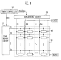
- FIG. 4 is a block diagram showing an organic light emitting display according to an embodiment of the present invention.
- the organic light emitting display includes a display region 30, a scan driving circuit 10, a data driving circuit 20, and a timing controller 50.
- the display region 30 includes a plurality of pixels 40 formed at crossing areas of scan lines S1 to Sn, emission control lines E1 to En, and data lines D1 to Dm.
- the scan driving circuit 10 drives the scan lines S1 to Sn.
- the data driving circuit 20 drives the data lines D 1 to Dm.
- the timing controller 50 controls the scan driving circuit 10 and the data driving circuit 20.
- the timing controller 50 generates a data drive control signal DCS and a scan drive control signal SCS according to externally supplied synchronous signals.
- the data drive control signal DCS generated by the timing controller 50 is provided to the data driving circuit 20, and the scan drive control signal SCS is provided to the scan driving circuit 10. Furthermore, the timing controller 50 provides externally supplied data Data to the data driving circuit 20.
- the data driving circuit 20 receives the data drive control signal DCS from the timing controller 50. Upon the receipt of the data drive control signal DCS, the data driving circuit 20 generates data signals, and provides the generated data signals to the data lines D1 to Dm. In this embodiment, the data driving circuit 20 provides the generated data signals to the data lines D1 to Dm every one horizontal period.
- the display region 30 receives a first power from a first power supply ELVDD and a second power from a second power supply ELVSS from an exterior source, and provides them to the pixels 40.
- the pixels 40 control an amount of current that flows into the second power supply ELVSS from the first power supply ELVDD through a light emitting element corresponding to the data signal, thus generating light corresponding to the data signal.
- the scan driving circuit 10 generates a scan signal in response to a scan drive control signal SCS from the timing controller 50, and sequentially provides the generated scan signal to the scan lines S1 to Sn. That is, the scan driving circuit 10 sequentially generates the scan signal to drive the plurality of pixels, and provide the scan signal to the display region 10.
- FIG. 5 is a block diagram showing a configuration of a scan driving circuit according to the present invention.
- the scan driving circuit includes n stages that are dependently connected with a start pulse input line so as to drive an m x n pixel array.
- First output lines of the first n stages are connected with first n row lines corresponding to the scan lines S 1 to Sn included in the pixel array.
- a start pulse SP is supplied to a first stage.
- Output signals of first to n-1 th stages are provided to next stages as a start pulse, respectively.
- Each stage receives and operates according to a first clock signal CLKclock signal CLK1 and a second clock signal CLKclock signal CLK2, the second clock signal CLKclock signal CLK2 and a third clock signal CLKclock signal CLK3 or the first clock signal CLKclock signal CLK1 and the third clock signal CLKclock signal CLK3. That is, each stage operates in response to two clocks selected from the first clock signal CLK1, the second clock signal CLK2 and the third clock signal CLK3, but does not operate in response to merely one clock.
- Each stage includes a first clock terminal ck1 and a second clock terminal ck2.
- the first clock signal CLKclock signal CLK1 and the second clock signal CLKclock signal CLK2 are supplied to the first clock terminal ck1 and the second clock terminal ck2 of a (3k-2)-th stages.
- the second clock signal CLKclock signal CLK2 and the third clock signal CLKclock signal CLK3 are supplied to the first clock terminal ck1 and the second clock terminal ck2 of a (3k)-th stages.
- the first clock signal CLKclock signal CLK1 and the third clock signal CLKclock signal CLK3 are supplied to the second clock terminal ck2 and the first clock terminal ck1 of a (3k-2)-th stages.
- k is a natural number.
- the second stage receives and operates according to the second and third clock signals.
- the third stage receives and operates according to the third and first clocksignals. That is, the first, second, and third stages sequentially output the signal to sequentially drive a display region of an organic light emitting display by scan lines.
- An external control circuit (not shown) provides the input signals of the driving circuit, that is, a start pulse SP, the first clock signal, the second clock signal and the third clock signal, CLK1, CLK2 and CLK3, and a supply voltage VDD.
- FIG. 6 is a circuit diagram showing a a stage for the scan driving circuit shown in FIG. 5 in accordance with a first embodiment of the invention.
- FIG. 7 is a timing diagram showing an input/output waveform of the stage shown in FIG. 6.
- transistors included in each stage are all PMOS transistors, and sequentially send a low level output through the scan driving circuit.
- the scan driving circuit of the present invention outputs a high level signal to a display region of an active matrix type display device such as an organic light emitting display for most of the time, and sequentially outputs a low level pulse through a plurality of stages as shown in FIGs. 6 and 7.
- the stage includes a first PMOS transistor M1, a second PMOS transistor M2, a third PMOS transistor M3, a fourth PMOS transistor M4, a fifth PMOS transistor M5, and a first capacitor C1.
- the first PMOS transistor M1 includes a gate connected with a first clock terminal ck1, receives an output voltage Si of a previous stage or a first start pulse SP, and selectively transfers the output voltage Si of a previous stage or the first start pulse SP to a first node N1.
- the second PMOS transistor M2 includes a gate connected to the first node N1, and is connected between the second clock terminal ck2 and a second node N2.
- the third PMOS transistor M3 includes a gate connected to the first clock terminal ck1, and is connected between a ground voltage source and a third node N3.
- the fourth PMOS transistor M4 includes a gate connected to the first node N1, and is connected between the first clock terminal ck1 and the third node N3.
- the fifth PMOS transistor M5 includes a gate connected to the third node N3, and is connected between a power supply VDD and the second node N2.
- the first capacitor C l is connected between the first node N 1 and the second node N2, and maintains a predetermined voltage.
- ground voltage source VSS is embodied by a ground GND, it can be either ground or a negative voltage power supply.
- each stage of the scan driving circuit may divide one period into a precharge period, an evaluation period, and a quiescent period according to the first clock signal CLKclock signal CLK1, the second clock signal CLKclock signal CLK2, and the third clock signal CLKclock signal CLK3.
- the precharge period the first clock signal CLKclock signal CLK1 of a low level is inputted to a first clock terminal ck1 of the stage, the second clock signal CLKclock signal CLK2 of a high level is inputted to the second clock terminal ck2.
- a start pulse SP or a scan signal Si of a previous stage is inputted to the input clock terminal In.
- the first PMOS transistor M 1 and the third PMOS transistor M3 are turned-on in response to a first clock to maintain the first node N1 and the third node N3 at a low level voltage.
- the second PMOS transistor M2 and the fourth PMOS transistor M4 are turned-on.
- the capacitor C 1 is charged with a voltage corresponding to a difference between voltages of the first node N1 and the second node N2.
- the fourth transistor M4 is turned-on, a voltage of the first clock signal CLKclock signal CLK1 is inputted to the third node N3. Consequently, the fifth PMOS transistor M5 is turned-on to output a drive voltage to an output terminal out.
- a first clock signal CLKclock signal CLK1 of a high level is inputted to the first clock terminal ck1
- a second clock signal CLKclock signal CLK2 of a low level is inputted to the second clock terminal ck2.
- the first PMOS transistor M1 is turned-on and becomes a floating-state, so that the first node N1 maintains a previous voltage by the capacitor C1.
- the second PMOS transistor M2 and the fourth PMOS transistor M4 are turned-on.
- the fourth PMOS transistor M4 is turned-on, the first clock signal CLKclock signal CLK1 transferred to the first clock terminal ck1 becomes a high level, with the result that the fifth PMOS transistor M5 is turned-off.
- a voltage of the second node N2 is varied according to a voltage of the second clock signal CLKclock signal CLK2, with the result that a voltage of the output terminal has the same waveform as that of the second clock signal CLKclock signal CLK2.
- a drive voltage from a power supply VDD is not transferred to the output terminal out by the fifth PMOS transistor M5, a voltage of the output terminal changes according to a voltage of the second node N2.
- the quiescent period indicates when the third clock signal CLKclock signal CLK3 has a low level.
- a first clock signal CLKclock signal CLK1 and a second clock signal CLKclock signal CLK2 of high level are transferred to the stage, whereas the third clock signal CLKclock signal CLK3 is not transferred thereto.
- the output terminal maintains a high level voltage.
- the first node N1 has a high level voltage by a capacitor, and the output terminal also maintains a high level voltage. Furthermore, in a state that the start pulse SP or the scan signal Si of a previous stage are not transferred through an input terminal In, when the first and second clocks of low level are transferred, the first node N1 maintains a high level voltage, and the second PMOS transistor M2 and the fifth PMOS transistor M5 are turned-off. Accordingly, a voltage of the output terminal depends on a voltage of the second node N2, and the second PMOS transistor M2 is turned-off, so that a voltage of the second node N2 maintains a high level without variation.
- each stage when a low level signal is not inputted to an input terminal In of each stage, the output terminal out maintains a high level signal, so that each stage receives an output low level signal of the previous stage and outputs a low level signal that results in a sequential output of the scan signal.
- FIG. 8 is a circuit diagram showing a stage for the scan driving circuit shown in FIG. 5 according to a second embodiment of the invention.
- the stage includes a first PMOS transistor M1, a second PMOS transistor M2, a third PMOS transistor M3, a fourth PMOS transistor M4, a fifth PMOS transistor M5, and a capacitor C1.
- the first PMOS transistor M 1 transfers an input signal to the first node N1 in response to the second clock signal CLK2, and the second PMOS transistor M2 transfers the third clock signal CLK3 to the second node N2 corresponding to a voltage of the first node N1.
- the third PMOS transistor M3 transfers a ground voltage to a gate of the fifth transistor PMOS M5 in response to the first clock signal CLK1.
- a gate of the fourth PMOS transistor M4 is connected to the output terminal out, and the fourth transistor M4 transfers the first clock signal CLK1 to a gate of the fifth PMOS transistor M5 corresponding to a voltage of the output terminal out.
- the fifth PMOS transistor M5 transfers a voltage of a power supply VDD to the output terminal corresponding to a voltage of a gate thereof.
- the capacitor C1 is connected between the first node N1 and the second node N2, and maintains a predetermined voltage.
- the stage having the construction as described above receives and operates according to the first clock and the second clock signal CLK1 and CLK2 among the first clock signal, the second clock signal and the third clock signal, CLK1, CLK2 and CLK3 shown in FIG. 7.
- the stage When the first clock signal CLK1 is low, the stage operates in a precharge mode.
- the second clock signal CLK2 is low, the stage operates in an evaluation mode.
- the third clock signal CLK3 is low, the stage operates in a quiescent mode.
- FIG. 9 is a circuit diagram showing a stage for the scan driving circuit shown in FIG. 5 in accordance with a third embodiment of the invention.
- the stage has substantially the same functions as that of FIG. 8.
- the difference between the stage of FIG. 9 from that of the stage of FIG. 8 is that the first clock signal CLK1 is transferred to a source and a gate of the third PMOS transistor M3. Accordingly, when the first clock signal CLK1 has a low level, the fifth PMOS transistor M5 is turned-on. Since all other components of the stage in FIG. 9 are arranged in substantially the same manner as the corresponding components of FIg. 8, they will not be described in detail.
- FIG. 10A and FIG. 10B are timing diagrams showing input/output waveforms of the stages shown in FIG. 8 and FIG. 9, respectively.
- FIG. 10A and FIG. 10B show operations of the stage when at least two of the first clock signal, the second clock signal and the third clock signal, CLK1, CLK2 and CLK3 overlap with each other by external influences.
- FIG. 10A indicates an operation of the stage when the first clock signal and the second clock signal, CLK1 and CLK2 overlap with each other.
- FIG. 10B indicates an operation of the stage when the first clock signal, the second clock signal and the third clock signal, CLK1, CLK2 and CLK3 overlap with each other.
- the scan signal appears to have a normal waveform periodically, so that a difference between a waveform of a scan signal inputted to a first scan line and a waveform of a scan signal inputted to a second scan line is not great.
- FIG. 11 is a circuit diagram showing a stage for the scan driving circuit shown in FIG. 5 in accordance with a fourth embodiment of the invention.
- FIG. 12 is a timing diagram of the stage shown in FIG. 11.
- the stage is formed of NMOS transistors.
- the stage includes a first NMOS transistor M6, a second NMOS transistor M7, a third NMOS transistor M8, a fourth NMOS transistor M9, a fifth NMOS transistor M 10 and a capacitor C 1.
- Each stage of FIG. 11 and FIG. 12 has similar construction to that of FIG. 6, and operates to have a precharge period, an evaluation period and a quiescent period.
- scan driving circuits and an organic light emitting displays using the same switch an output voltage from a positive source voltage to a negative source voltage, their operation speed may be increased. Furthermore, even if a clock signal transferred to the scan driving circuit is erroneously operated, the consequent change in the waveform of the scan signal need not be great.
Abstract

Description
- [0002] The present invention relates to a scan driving circuit and an organic light emitting display using the same.
- Recently, various flat panel displays devices with a small weight and volume compared with a cathode ray tube have been developed. Such a flat panel display device comprises a plurality of pixels arranged on a substrate in a matrix to form a pixel unit. Scan lines and data lines are connected to each pixel in order to apply data signals selectively to the pixels for display purposes.
- Flat panel display devices can be categorized as either a passive matrix type display devices or active matrix type display devices in accordance with the driving scheme used for the pixels. The active matrix type has more commonly been used in view of the advantages it offers in terms of resolution, contrast and operation speed. Such a flat panel display device has been used as a display device of a portable information terminal such as a personal computer, a mobile telephone, a PDA, etc., or a monitor for various types of information equipment.
- An LCD using a liquid crystal panel, an organic electro luminescence display using organic light-emitting element and a PDP using a plasma panel, etc., are known types of flat panel display. The organic electro luminescence display, which typically performs excellently in terms of emission efficiency, brightness, view angle and response speed, has been the focus of much affection.
- In general, an active matrix type display device such as an organic light emitting display includes a pixel array arranged at crossings between data lines and scan lines in a matrix pattern.
- Here, the scan lines include horizontal lines (i.e., row lines) of a matrix display region, and sequentially provide a predetermined signal, namely, a scan signal, from a scan driving circuit, to the pixel array.
- The present invention sets out to solve the above problems and accordingly provides a sacan-driving circuit as set out in
claim 1 and an organic light emitting display as set out in claim 14. Preferred features of the invention are set out inclaims 2 to 13. - Embodiments of the invention will be described by way of example and with reference to the accompanying drawings, in which:
- FIG. 1 is a block diagram showing a conventional scan driving circuit;
- FIG. 2 is a circuit diagram of a stage in the scan driving circuit shown in FIG. 1;
- FIG. 2A is a circuit diagram of one of the inverters shown in FIG. 2;
- FIG. 3 is a timing diagram of the stage shown in FIG. 2;
- FIG. 4 is a block diagram showing an organic light emitting display according to the present invention;
- FIG. 5 is a block diagram showing a construction of a scan driving circuit according to the present invention;
- FIG. 6 is a circuit diagram showing a stage for the scan driving circuit shown in FIG. 5 in accordance with a first embodiment of the invention;
- FIG. 7 is a timing diagram showing an input/output waveform of the stage shown in FIG. 6;
- FIG. 8 is a circuit diagram showing stage for the scan driving circuit shown in FIG. 5 in accordance with a second embodiment of the invention;
- FIG. 9 is a circuit diagram showing a stage for the scan driving circuit shown in FIG. 5 in accordance with a third embodiment of the invention;
- FIG. 10A and FIG. 10B are timing diagrams showing input/output waveforms of the stages shown in FIG. 8 and FIG. 9, respectively;
- FIG. 11 is a circuit diagram showing a stage for the scan driving circuit shown in FIG. 5 in accordance with a fourth embodiment of the invention; and
- FIG. 12 is a timing diagram of the stage shown in FIG. 11.
- Hereinafter, certain embodiments of the present invention will be described with reference to the accompanying drawings. Here, when a first element is described as being connected to a second element, the first element may be not only directly connected to the second element but may also be indirectly connected to the second element via a third element. Further, elements that are not essential to the complete understanding of the invention are omitted for clarity. Also, like reference numerals refer to like elements throughout.
- FIG. 1 is the block diagram showing a conventional scan driving circuit. With reference to FIG. 1, the conventional scan driving circuit includes a plurality of stages ST1 to STn, which are dependently connected with a start pulse SP input line. The plurality of
stages ST 1 to STn sequentially shift a clock signal C in response to a start pulse SP to generate output signals SO1 to SOn, respectively. In this case, each of second to n-th stages ST2 to STn receives and shifts an output signal of a previous stage as a start pulse. - Accordingly, the stages generate output signals SO1 to SOn in such a way that the start pulse is sequentially shifted, and provide the output signals to the pixel array.
- FIG. 2 is a circuit diagram of a stage in the scan driving circuit shown in FIG. 1. FIG. 3 is a timing diagram of the stage shown in FIG. 2. Referring to FIG. 2 and FIG. 3, conventionally, each stage of a scan driving circuit uses a master-slave flip-flop. When a clock signal CLK is at a low level, such a flip-flop continues to receive an input and maintains a previous output.
- In contrast to this, when the clock signal CLK is at a high level, the flip-flop maintains an input received at an input terminal In received when the clock signal CLK is at the low level, and outputs the received input but no longer receives the input shown.
- In the aforementioned circuit, an inverter included in the flip-flop shown in FIG. 2A experiences a problem in that a static current flows when an input thereof is at a low level. Furthermore, in the flip-flop, the number of inverters having received a high-level input is the same number as that of inverters having received a low-level input. Accordingly, the static current flows through a half of all the inverters M1' and M2' in the flip-flop, thereby causing power consumption to be increased.
- In addition, in the circuit of FIG. 2A, a voltage value due to a ratio of resistance (i.e., the transistors M1' and M2') connected between a power supply VDD and a ground GND determines a high level of an output voltage out. A low level of the output voltage out is set to be greater than that of the ground GND by a threshold voltage of the transistor M2'.
- By way of example, due to characteristic deviations of the transistors, since levels of an input voltage are different according to respective stages, in the case where the circuits of FIGs. 2 and 2A are used, the deviation occurs when the output voltage is at a high level, with the result that the circuit may be erroneously operated.
- Moreover, the deviation in a low level of the output voltage causes a deviation in on-resistance of an input transistor of an inverter included in the circuit of FIG. 2 to occur, thereby weighting a deviation in a high level of the output voltage. In particular, since a panel of an organic light emitting display uses a transistor having a great characteristic deviation, such a problem is more serious.
- Further, in the inverter, an electric current flows through an input transistor to charge an output terminal, whereas the electric current flows through a load transistor to discharge the output terminal. Upon a charge of the output terminal, a source-gate voltage of the load transistor is gradually reduced, and a discharge current is accordingly reduced rapidly. This causes the discharge efficiency to be deteriorated.
- FIG. 4 is a block diagram showing an organic light emitting display according to an embodiment of the present invention. With reference to FIG. 4, the organic light emitting display includes a
display region 30, ascan driving circuit 10, adata driving circuit 20, and atiming controller 50. - The
display region 30 includes a plurality ofpixels 40 formed at crossing areas of scan lines S1 to Sn, emission control lines E1 to En, and data lines D1 to Dm. Thescan driving circuit 10 drives the scan lines S1 to Sn. Thedata driving circuit 20 drives thedata lines D 1 to Dm. Thetiming controller 50 controls thescan driving circuit 10 and thedata driving circuit 20. - The
timing controller 50 generates a data drive control signal DCS and a scan drive control signal SCS according to externally supplied synchronous signals. The data drive control signal DCS generated by thetiming controller 50 is provided to thedata driving circuit 20, and the scan drive control signal SCS is provided to thescan driving circuit 10. Furthermore, thetiming controller 50 provides externally supplied data Data to thedata driving circuit 20. - The
data driving circuit 20 receives the data drive control signal DCS from thetiming controller 50. Upon the receipt of the data drive control signal DCS, thedata driving circuit 20 generates data signals, and provides the generated data signals to the data lines D1 to Dm. In this embodiment, thedata driving circuit 20 provides the generated data signals to the data lines D1 to Dm every one horizontal period. - The
display region 30 receives a first power from a first power supply ELVDD and a second power from a second power supply ELVSS from an exterior source, and provides them to thepixels 40. Upon the receipt of the first power and the second power, thepixels 40 control an amount of current that flows into the second power supply ELVSS from the first power supply ELVDD through a light emitting element corresponding to the data signal, thus generating light corresponding to the data signal. - The
scan driving circuit 10 generates a scan signal in response to a scan drive control signal SCS from thetiming controller 50, and sequentially provides the generated scan signal to the scan lines S1 to Sn. That is, thescan driving circuit 10 sequentially generates the scan signal to drive the plurality of pixels, and provide the scan signal to thedisplay region 10. - Hereinafter, a construction and an operation of the scan driving circuit of an organic light emitting display according to an embodiment of the present invention will be explained.
- FIG. 5 is a block diagram showing a configuration of a scan driving circuit according to the present invention. Referring to FIG. 5, the scan driving circuit includes n stages that are dependently connected with a start pulse input line so as to drive an m x n pixel array.
- First output lines of the first n stages are connected with first n row lines corresponding to the scan lines S 1 to Sn included in the pixel array. A start pulse SP is supplied to a first stage. Output signals of first to n-1 th stages are provided to next stages as a start pulse, respectively. Each stage receives and operates according to a first clock signal CLKclock signal CLK1 and a second clock signal CLKclock signal CLK2, the second clock signal CLKclock signal CLK2 and a third clock signal CLKclock signal CLK3 or the first clock signal CLKclock signal CLK1 and the third clock signal CLKclock signal CLK3. That is, each stage operates in response to two clocks selected from the first clock signal CLK1, the second clock signal CLK2 and the third clock signal CLK3, but does not operate in response to merely one clock.
- Each stage includes a first clock terminal ck1 and a second clock terminal ck2. In the arrangement shown, the first clock signal CLKclock signal CLK1 and the second clock signal CLKclock signal CLK2 are supplied to the first clock terminal ck1 and the second clock terminal ck2 of a (3k-2)-th stages. The second clock signal CLKclock signal CLK2 and the third clock signal CLKclock signal CLK3 are supplied to the first clock terminal ck1 and the second clock terminal ck2 of a (3k)-th stages. The first clock signal CLKclock signal CLK1 and the third clock signal CLKclock signal CLK3 are supplied to the second clock terminal ck2 and the first clock terminal ck1 of a (3k-2)-th stages. Here, k is a natural number.
- clock signal CLKclock signal CLKclock signal CLKWhen the first stage outputs a signal in response to the first and second clock signals, the second stage receives and operates according to the second and third clock signals. When the second stage outputs a signal in response to the second and third clock signals, the third stage receives and operates according to the third and first clocksignals. That is, the first, second, and third stages sequentially output the signal to sequentially drive a display region of an organic light emitting display by scan lines.
- An external control circuit (not shown) provides the input signals of the driving circuit, that is, a start pulse SP, the first clock signal, the second clock signal and the third clock signal, CLK1, CLK2 and CLK3, and a supply voltage VDD.
- FIG. 6 is a circuit diagram showing a a stage for the scan driving circuit shown in FIG. 5 in accordance with a first embodiment of the invention. FIG. 7 is a timing diagram showing an input/output waveform of the stage shown in FIG. 6.
- As shown in FIG. 6, in this embodiment of the present invention, transistors included in each stage are all PMOS transistors, and sequentially send a low level output through the scan driving circuit. Namely, the scan driving circuit of the present invention outputs a high level signal to a display region of an active matrix type display device such as an organic light emitting display for most of the time, and sequentially outputs a low level pulse through a plurality of stages as shown in FIGs. 6 and 7.
- Referring to FIG. 6, the stage includes a first PMOS transistor M1, a second PMOS transistor M2, a third PMOS transistor M3, a fourth PMOS transistor M4, a fifth PMOS transistor M5, and a first capacitor C1. The first PMOS transistor M1 includes a gate connected with a first clock terminal ck1, receives an output voltage Si of a previous stage or a first start pulse SP, and selectively transfers the output voltage Si of a previous stage or the first start pulse SP to a first node N1. The second PMOS transistor M2 includes a gate connected to the first node N1, and is connected between the second clock terminal ck2 and a second node N2. The third PMOS transistor M3 includes a gate connected to the first clock terminal ck1, and is connected between a ground voltage source and a third node N3. The fourth PMOS transistor M4 includes a gate connected to the first node N1, and is connected between the first clock terminal ck1 and the third node N3. The fifth PMOS transistor M5 includes a gate connected to the third node N3, and is connected between a power supply VDD and the second node N2. The first capacitor C l is connected between the
first node N 1 and the second node N2, and maintains a predetermined voltage. - Although it is shown that the ground voltage source VSS is embodied by a ground GND, it can be either ground or a negative voltage power supply.
- Hereinafter, through a circuit arrangement of the (3k-2)-th stage among the stages shown in FIG. 5, the operation of the stages will be explained.
- With reference to FIGs. 6 and 7, each stage of the scan driving circuit may divide one period into a precharge period, an evaluation period, and a quiescent period according to the first clock signal CLKclock signal CLK1, the second clock signal CLKclock signal CLK2, and the third clock signal CLKclock signal CLK3. During the precharge period, the first clock signal CLKclock signal CLK1 of a low level is inputted to a first clock terminal ck1 of the stage, the second clock signal CLKclock signal CLK2 of a high level is inputted to the second clock terminal ck2. Further, a start pulse SP or a scan signal Si of a previous stage is inputted to the input clock terminal In. At this time, the first
PMOS transistor M 1 and the third PMOS transistor M3 are turned-on in response to a first clock to maintain the first node N1 and the third node N3 at a low level voltage. When the first node N1 becomes a low level, the second PMOS transistor M2 and the fourth PMOS transistor M4 are turned-on. When the second PMOS transistor M2 is turned-on, thecapacitor C 1 is charged with a voltage corresponding to a difference between voltages of the first node N1 and the second node N2. Further, when the fourth transistor M4 is turned-on, a voltage of the first clock signal CLKclock signal CLK1 is inputted to the third node N3. Consequently, the fifth PMOS transistor M5 is turned-on to output a drive voltage to an output terminal out. - During the evaluation period, a first clock signal CLKclock signal CLK1 of a high level is inputted to the first clock terminal ck1, and a second clock signal CLKclock signal CLK2 of a low level is inputted to the second clock terminal ck2. At this time, the first PMOS transistor M1 is turned-on and becomes a floating-state, so that the first node N1 maintains a previous voltage by the capacitor C1. Accordingly, the second PMOS transistor M2 and the fourth PMOS transistor M4 are turned-on. When the fourth PMOS transistor M4 is turned-on, the first clock signal CLKclock signal CLK1 transferred to the first clock terminal ck1 becomes a high level, with the result that the fifth PMOS transistor M5 is turned-off. Further, when the second PMOS transistor M2 is turned-on, a voltage of the second node N2 is varied according to a voltage of the second clock signal CLKclock signal CLK2, with the result that a voltage of the output terminal has the same waveform as that of the second clock signal CLKclock signal CLK2. In addition, since a drive voltage from a power supply VDD is not transferred to the output terminal out by the fifth PMOS transistor M5, a voltage of the output terminal changes according to a voltage of the second node N2.
- Finally, the quiescent period indicates when the third clock signal CLKclock signal CLK3 has a low level. During the quiescent period, a first clock signal CLKclock signal CLK1 and a second clock signal CLKclock signal CLK2 of high level are transferred to the stage, whereas the third clock signal CLKclock signal CLK3 is not transferred thereto. At this time, the output terminal maintains a high level voltage.
- Moreover, when the second clock signal CLK2 again becomes a low level, the first node N1 has a high level voltage by a capacitor, and the output terminal also maintains a high level voltage. Furthermore, in a state that the start pulse SP or the scan signal Si of a previous stage are not transferred through an input terminal In, when the first and second clocks of low level are transferred, the first node N1 maintains a high level voltage, and the second PMOS transistor M2 and the fifth PMOS transistor M5 are turned-off. Accordingly, a voltage of the output terminal depends on a voltage of the second node N2, and the second PMOS transistor M2 is turned-off, so that a voltage of the second node N2 maintains a high level without variation.
- Consequently, when a low level signal is not inputted to an input terminal In of each stage, the output terminal out maintains a high level signal, so that each stage receives an output low level signal of the previous stage and outputs a low level signal that results in a sequential output of the scan signal.
- FIG. 8 is a circuit diagram showing a stage for the scan driving circuit shown in FIG. 5 according to a second embodiment of the invention. Referring to FIG. 8, the stage includes a first PMOS transistor M1, a second PMOS transistor M2, a third PMOS transistor M3, a fourth PMOS transistor M4, a fifth PMOS transistor M5, and a capacitor C1.
- The first
PMOS transistor M 1 transfers an input signal to the first node N1 in response to the second clock signal CLK2, and the second PMOS transistor M2 transfers the third clock signal CLK3 to the second node N2 corresponding to a voltage of the first node N1. The third PMOS transistor M3 transfers a ground voltage to a gate of the fifth transistor PMOS M5 in response to the first clock signal CLK1. A gate of the fourth PMOS transistor M4 is connected to the output terminal out, and the fourth transistor M4 transfers the first clock signal CLK1 to a gate of the fifth PMOS transistor M5 corresponding to a voltage of the output terminal out. Further, the fifth PMOS transistor M5 transfers a voltage of a power supply VDD to the output terminal corresponding to a voltage of a gate thereof. Moreover, the capacitor C1 is connected between the first node N1 and the second node N2, and maintains a predetermined voltage. - The stage having the construction as described above receives and operates according to the first clock and the second clock signal CLK1 and CLK2 among the first clock signal, the second clock signal and the third clock signal, CLK1, CLK2 and CLK3 shown in FIG. 7. When the first clock signal CLK1 is low, the stage operates in a precharge mode. When the second clock signal CLK2 is low, the stage operates in an evaluation mode. When the third clock signal CLK3 is low, the stage operates in a quiescent mode.
- FIG. 9 is a circuit diagram showing a stage for the scan driving circuit shown in FIG. 5 in accordance with a third embodiment of the invention. In the stage shown in FIG. 9, the stage has substantially the same functions as that of FIG. 8. The difference between the stage of FIG. 9 from that of the stage of FIG. 8 is that the first clock signal CLK1 is transferred to a source and a gate of the third PMOS transistor M3. Accordingly, when the first clock signal CLK1 has a low level, the fifth PMOS transistor M5 is turned-on. Since all other components of the stage in FIG. 9 are arranged in substantially the same manner as the corresponding components of FIg. 8, they will not be described in detail.
- FIG. 10A and FIG. 10B are timing diagrams showing input/output waveforms of the stages shown in FIG. 8 and FIG. 9, respectively. FIG. 10A and FIG. 10B show operations of the stage when at least two of the first clock signal, the second clock signal and the third clock signal, CLK1, CLK2 and CLK3 overlap with each other by external influences. FIG. 10A indicates an operation of the stage when the first clock signal and the second clock signal, CLK1 and CLK2 overlap with each other. FIG. 10B indicates an operation of the stage when the first clock signal, the second clock signal and the third clock signal, CLK1, CLK2 and CLK3 overlap with each other.
- In the case of FIG. 10A, when the first clock signal and the second clock signal, CLK1 and CLK2 overlap with each other due to an erroneous operation of the second clock signal CLK2, they do not overlap with the third clock signal CLK3 of a normal operation. Accordingly, since the first clock signal and the second clock signal, CLK1 and CLK2 overlap with each other, a start part of a scan signal that a first stage outputs is distorted. However, because the second clock signal and the third clock signal, CLK2 and CLK3 overlap with each other, a second stage outputs a scan signal, which is not distorted. Further, the third clock signal CLK3 and a first clock signal CLK1 of the second time do not overlap with each other, in the event that a third stage outputs a scan signal, which is not distorted.
- In the case of FIG. 10B, when the first clock signal and the second clock signal, CLK1 and CLK2 overlap with each other, and the second clock signal and the third clock signal, CLK2 and CLK3 overlap with each other, the third clock signal CLK3 and a first clock signal CLK1 of the second time do not overlap with each other. Accordingly, the start parts of output scan signals of the first stage and the second stage are distorted, whereas an output scan signal of the third stage is not distorted.
- As a result, the scan signal appears to have a normal waveform periodically, so that a difference between a waveform of a scan signal inputted to a first scan line and a waveform of a scan signal inputted to a second scan line is not great.
- FIG. 11 is a circuit diagram showing a stage for the scan driving circuit shown in FIG. 5 in accordance with a fourth embodiment of the invention. FIG. 12 is a timing diagram of the stage shown in FIG. 11. With reference to FIG. 11, the stage is formed of NMOS transistors. The stage includes a first NMOS transistor M6, a second NMOS transistor M7, a third NMOS transistor M8, a fourth NMOS transistor M9, a fifth
NMOS transistor M 10 and acapacitor C 1. Each stage of FIG. 11 and FIG. 12 has similar construction to that of FIG. 6, and operates to have a precharge period, an evaluation period and a quiescent period. - Since scan driving circuits and an organic light emitting displays using the same according to the present invention switch an output voltage from a positive source voltage to a negative source voltage, their operation speed may be increased. Furthermore, even if a clock signal transferred to the scan driving circuit is erroneously operated, the consequent change in the waveform of the scan signal need not be great.
- Although embodiments of the present invention have been shown and described, it would be appreciated by those skilled in the art that changes might be made in these embodiments without departing from the principles of the invention, the scope of which is defined in the claims and their equivalents.
Claims (14)
- A scan driving circuit comprising a plurality of stages, the plurality of stages being collectively adapted to receive three clock signals, wherein each of the plurality of stages is respectively configured to receive two of the three said clock signals, to receive and delay an input signal through an input terminal, and to output an output signal through an output terminal, wherein the input terminal of each of the plurality of stages is connected to the output terminal of a previous one of the stages, wherein each of the plurality of stages comprises:a switch for turning on/off a connection of the input terminal according to a first said clock signal, the first clock signal being input through a first clock terminal;a switch section for transferring a first voltage to the output terminal according to the first said clock signal; anda storage section for maintaining a voltage of the output terminal for a predetermined time, and for transferring a voltage of a said second clock signal to the output terminal according to the input signal, the said second clock being input through a second clock terminal.
- A scan driving circuit according to claim 1, wherein each switch section is adapted to prevent the first voltage from being transferred to the output terminal in accordance with the input signal.
- A scan driving circuit as claimed in claim 1 or 2, wherein each storage section comprises:a first transistor connected to the switch for transferring the second clock signal to a second node according to a voltage of a first node that received the input signal; anda capacitor for maintaining a voltage between the first node and the second node.
- A scan driving circuit as claimed in claim 1, 2 or 3, wherein each switch section comprises:a first transistor for transferring a second voltage to a third node according toa voltage of the first clock signal;a second transistor for transferring the voltage of the first clock signal to the third node according to the input signal, wherein the third node is between the first transistor and the second transistor; anda third transistor including a gate connected to the third node, the third transistor being for transferring the first voltage to the output terminal according to a voltage of the third node.
- A scan driving circuit as claimed in one of claims 1 to 3, wherein each switch section comprises:a first transistor for transferring a second voltage to a third node according to a voltage of the first clock signal;a second transistor including a gate connected to the output terminal, a source connected to the first clock terminal, and a drain connected to the third node; anda third transistor including a gate connected to the third node, a source connected to the first voltage, and a drain connected to the output terminal.
- A scan driving circuit as claimed in claim 4 or 5, wherein the second voltage is a ground voltage.
- A scan driving circuit as claimed in one of claims 1 to 3, wherein each switch section comprises:a first transistor including a gate and a source connected to the first clock terminal, and a drain connected to a third node;a second transistor including a gate connected to the output terminal, a source connected to the first clock terminal, and a drain connected to the third node; anda third transistor including a gate connected to the third node, a source connected to the first voltage, and a drain connected to the output terminal.
- A scan driving circuit as claimed in claim 7, wherein each of the plurality of stages is adapted to operate in an input period when the previous one of the stages outputs a low level signal.
- A scan driving circuit as claimed in one of claims 1 to 3, wherein each switch section comprises:a first transistor including a gate connected to the first clock terminal, a source connected to a second voltage, and a drain connected to a second node;a second transistor including a gate connected to a first node, a source connected to the first clock terminal, and a drain connected to the second node; anda third transistor including a gate connected to the second node, a drain connected to a first voltage, and a source connected to the output terminal.
- A scan driving circuit as claimed in any preceding claim, wherein the plurality of stages are adapted to operate during a precharge period, an evaluation period, and a quiescent period, wherein each of the plurality of stages is adapted to receive the input signal in response to the first clock signal during the precharge period, to output to the output terminal a voltage corresponding to the second clock signal during the evaluation period, and to output a signal stored in the storage section while a third said clock signal generating.
- A scan driving circuit as claimed in claim 10, wherein each of the plurality of stages is adapted to operate in an input mode when a previous one of the stages outputs a scan signal.
- A scan driving circuit as claimed in any preceding claim, wherein the first voltage is a voltage of a drive power source.
- A scan driving circuit according to any preceding claim wherein the said switch is a transistor.
- An organic light emitting display comprising:a display region having a plurality of pixels for displaying an image;a scan driving circuit for transferring a scan signal to the display region; anda data driving circuit for transferring a data signal to the display region,wherein the scan driving circuit is as set out in any preceding claim.
Applications Claiming Priority (1)
| Application Number | Priority Date | Filing Date | Title |
|---|---|---|---|
| KR1020060034959A KR100776510B1 (en) | 2006-04-18 | 2006-04-18 | Scan driving circuit and organic light emitting display using the same |
Publications (2)
| Publication Number | Publication Date |
|---|---|
| EP1848000A1 true EP1848000A1 (en) | 2007-10-24 |
| EP1848000B1 EP1848000B1 (en) | 2011-10-19 |
Family
ID=38068558
Family Applications (1)
| Application Number | Title | Priority Date | Filing Date |
|---|---|---|---|
| EP07251408A Active EP1848000B1 (en) | 2006-04-18 | 2007-03-30 | Scan driving circuit and organic light emitting display using the same |
Country Status (5)
| Country | Link |
|---|---|
| US (1) | US7920118B2 (en) |
| EP (1) | EP1848000B1 (en) |
| JP (1) | JP2007286582A (en) |
| KR (1) | KR100776510B1 (en) |
| CN (1) | CN101059934B (en) |
Families Citing this family (8)
| Publication number | Priority date | Publication date | Assignee | Title |
|---|---|---|---|---|
| JP4932415B2 (en) * | 2006-09-29 | 2012-05-16 | 株式会社半導体エネルギー研究所 | Semiconductor device |
| KR20120033672A (en) | 2010-09-30 | 2012-04-09 | 삼성모바일디스플레이주식회사 | Driver, display device comprising the same |
| CN104751769A (en) * | 2013-12-25 | 2015-07-01 | 昆山工研院新型平板显示技术中心有限公司 | Scanning driver and organic light emitting display employing same |
| CN104200769B (en) * | 2014-08-19 | 2016-09-28 | 上海和辉光电有限公司 | Generation circuit of scanning signals |
| CN104751816B (en) * | 2015-03-31 | 2017-08-15 | 深圳市华星光电技术有限公司 | Shift-register circuit |
| CN105185411B (en) * | 2015-06-30 | 2019-03-26 | 上海天马有机发光显示技术有限公司 | A kind of shift register and its driving method |
| CN105739202A (en) * | 2016-05-10 | 2016-07-06 | 京东方科技集团股份有限公司 | Array base plate and display device |
| CN114283758B (en) * | 2021-12-30 | 2023-01-10 | 惠科股份有限公司 | Display panel, pre-charging method of display panel and display device |
Citations (3)
| Publication number | Priority date | Publication date | Assignee | Title |
|---|---|---|---|---|
| EP0651395A2 (en) | 1993-10-28 | 1995-05-03 | RCA Thomson Licensing Corporation | Shift register useful as a select line scanner for a liquid crystal display |
| US6339631B1 (en) | 1999-03-02 | 2002-01-15 | Lg. Philips Lcd Co., Ltd. | Shift register |
| EP1764773A2 (en) | 2005-09-20 | 2007-03-21 | Samsung SDI Co., Ltd. | Scan driving ciruit and organic light emitting display using the same |
Family Cites Families (19)
| Publication number | Priority date | Publication date | Assignee | Title |
|---|---|---|---|---|
| US5222082A (en) * | 1991-02-28 | 1993-06-22 | Thomson Consumer Electronics, S.A. | Shift register useful as a select line scanner for liquid crystal display |
| JP4086046B2 (en) | 1998-05-14 | 2008-05-14 | カシオ計算機株式会社 | SHIFT REGISTER, DISPLAY DEVICE, IMAGING ELEMENT DRIVE DEVICE, AND IMAGING DEVICE |
| KR100438525B1 (en) * | 1999-02-09 | 2004-07-03 | 엘지.필립스 엘시디 주식회사 | Shift Register Circuit |
| DE19950860B4 (en) * | 1998-10-21 | 2009-08-27 | Lg Display Co., Ltd. | shift register |
| JP3809750B2 (en) | 1999-12-02 | 2006-08-16 | カシオ計算機株式会社 | Shift register and electronic device |
| JP4761643B2 (en) * | 2001-04-13 | 2011-08-31 | 東芝モバイルディスプレイ株式会社 | Shift register, drive circuit, electrode substrate, and flat display device |
| KR100776500B1 (en) * | 2001-05-07 | 2007-11-16 | 엘지.필립스 엘시디 주식회사 | Shift Resistor Circuit |
| JP2003101394A (en) | 2001-05-29 | 2003-04-04 | Semiconductor Energy Lab Co Ltd | Pulse output circuit, shift register and display unit |
| US7050036B2 (en) * | 2001-12-12 | 2006-05-23 | Lg.Philips Lcd Co., Ltd. | Shift register with a built in level shifter |
| JP4460822B2 (en) * | 2002-11-29 | 2010-05-12 | 東芝モバイルディスプレイ株式会社 | Bidirectional shift register, drive circuit using the same, and flat display device |
| KR20040097503A (en) * | 2003-05-12 | 2004-11-18 | 엘지.필립스 엘시디 주식회사 | Shift register |
| JP4189585B2 (en) | 2003-09-17 | 2008-12-03 | カシオ計算機株式会社 | Shift register circuit and electronic device |
| JP2005166139A (en) | 2003-12-01 | 2005-06-23 | Seiko Epson Corp | Shift register, method and circuit for driving the same, electrooptic device, and electronic device |
| CN100385478C (en) * | 2003-12-27 | 2008-04-30 | Lg.菲利浦Lcd株式会社 | Driving circuit including shift register and flat panel display device using the same |
| KR101012972B1 (en) * | 2003-12-30 | 2011-02-10 | 엘지디스플레이 주식회사 | Active matrix display device |
| JP4645047B2 (en) | 2004-03-05 | 2011-03-09 | カシオ計算機株式会社 | Shift register circuit, drive control method thereof, and drive control apparatus |
| US7639226B2 (en) * | 2004-05-31 | 2009-12-29 | Lg Display Co., Ltd. | Liquid crystal display panel with built-in driving circuit |
| JP2006127630A (en) | 2004-10-28 | 2006-05-18 | Alps Electric Co Ltd | Shift register and liquid crystal driver |
| KR100776511B1 (en) * | 2006-04-18 | 2007-11-16 | 삼성에스디아이 주식회사 | Scan driving circuit and organic light emitting display using the same |
-
2006
- 2006-04-18 KR KR1020060034959A patent/KR100776510B1/en active IP Right Grant
- 2006-10-24 JP JP2006288816A patent/JP2007286582A/en active Pending
-
2007
- 2007-03-28 US US11/692,880 patent/US7920118B2/en active Active
- 2007-03-30 EP EP07251408A patent/EP1848000B1/en active Active
- 2007-04-17 CN CN200710101316XA patent/CN101059934B/en active Active
Patent Citations (3)
| Publication number | Priority date | Publication date | Assignee | Title |
|---|---|---|---|---|
| EP0651395A2 (en) | 1993-10-28 | 1995-05-03 | RCA Thomson Licensing Corporation | Shift register useful as a select line scanner for a liquid crystal display |
| US6339631B1 (en) | 1999-03-02 | 2002-01-15 | Lg. Philips Lcd Co., Ltd. | Shift register |
| EP1764773A2 (en) | 2005-09-20 | 2007-03-21 | Samsung SDI Co., Ltd. | Scan driving ciruit and organic light emitting display using the same |
Also Published As
| Publication number | Publication date |
|---|---|
| CN101059934A (en) | 2007-10-24 |
| EP1848000B1 (en) | 2011-10-19 |
| JP2007286582A (en) | 2007-11-01 |
| CN101059934B (en) | 2011-01-26 |
| US20070242001A1 (en) | 2007-10-18 |
| KR20070103182A (en) | 2007-10-23 |
| KR100776510B1 (en) | 2007-11-16 |
| US7920118B2 (en) | 2011-04-05 |
Similar Documents
| Publication | Publication Date | Title |
|---|---|---|
| EP1847983B1 (en) | Scan driving circuit and organic light emitting display using the same | |
| US11127478B2 (en) | Shift register unit and driving method thereof, gate driving circuit, and display device | |
| EP1764774B1 (en) | Scan driving circuit and organic light emitting display using the same | |
| US9123310B2 (en) | Liquid crystal display device for improving the characteristics of gate drive voltage | |
| KR101857808B1 (en) | Scan Driver and Organic Light Emitting Display Device using thereof | |
| KR101966381B1 (en) | Shift register and flat panel display device thereof | |
| US7446570B2 (en) | Shift register, gate driving circuit and display panel having the same, and method thereof | |
| EP1848000B1 (en) | Scan driving circuit and organic light emitting display using the same | |
| EP1783777B1 (en) | Shift register circuit | |
| KR101352289B1 (en) | Display Device | |
| EP1783739A2 (en) | Data driving circuit and electroluminescent display using the same | |
| KR101366877B1 (en) | Display Device | |
| CN110313028B (en) | Signal generation method, signal generation circuit and display device | |
| CN111292664B (en) | Gate drive circuit, display panel and display method thereof | |
| US10748465B2 (en) | Gate drive circuit, display device and method for driving gate drive circuit | |
| KR20190079855A (en) | Shift register and display device including thereof | |
| KR20150079314A (en) | Display device and method of driving the same | |
| KR20110102627A (en) | Shift register and display device using the same | |
| KR20080011896A (en) | Gate on voltage generation circuit and gate off voltage generation circuit and liquid crystal display having the same | |
| US20070229409A1 (en) | Scan driving circuit and electroluminescent display using the same | |
| KR20150030541A (en) | Liquid crystal display device incuding gate driver | |
| CN109671382B (en) | Gate driving circuit and display device using the same | |
| US7893894B2 (en) | Organic light emitting display and driving circuit thereof | |
| KR20140131448A (en) | Scan Driver and Display Device Using the same | |
| CN113299223B (en) | Display panel and display device |
Legal Events
| Date | Code | Title | Description |
|---|---|---|---|
| PUAI | Public reference made under article 153(3) epc to a published international application that has entered the european phase |
Free format text: ORIGINAL CODE: 0009012 |
|
| 17P | Request for examination filed |
Effective date: 20070410 |
|
| AK | Designated contracting states |
Kind code of ref document: A1 Designated state(s): AT BE BG CH CY CZ DE DK EE ES FI FR GB GR HU IE IS IT LI LT LU LV MC MT NL PL PT RO SE SI SK TR |
|
| AX | Request for extension of the european patent |
Extension state: AL BA HR MK YU |
|
| AKX | Designation fees paid |
Designated state(s): DE FR GB HU |
|
| 17Q | First examination report despatched |
Effective date: 20081114 |
|
| RAP1 | Party data changed (applicant data changed or rights of an application transferred) |
Owner name: SAMSUNG MOBILE DISPLAY CO., LTD. |
|
| GRAP | Despatch of communication of intention to grant a patent |
Free format text: ORIGINAL CODE: EPIDOSNIGR1 |
|
| GRAS | Grant fee paid |
Free format text: ORIGINAL CODE: EPIDOSNIGR3 |
|
| GRAA | (expected) grant |
Free format text: ORIGINAL CODE: 0009210 |
|
| AK | Designated contracting states |
Kind code of ref document: B1 Designated state(s): DE FR GB HU |
|
| REG | Reference to a national code |
Ref country code: GB Ref legal event code: FG4D |
|
| REG | Reference to a national code |
Ref country code: DE Ref legal event code: R096 Ref document number: 602007017997 Country of ref document: DE Effective date: 20111222 |
|
| PLBE | No opposition filed within time limit |
Free format text: ORIGINAL CODE: 0009261 |
|
| STAA | Information on the status of an ep patent application or granted ep patent |
Free format text: STATUS: NO OPPOSITION FILED WITHIN TIME LIMIT |
|
| 26N | No opposition filed |
Effective date: 20120720 |
|
| REG | Reference to a national code |
Ref country code: DE Ref legal event code: R097 Ref document number: 602007017997 Country of ref document: DE Effective date: 20120720 |
|
| REG | Reference to a national code |
Ref country code: FR Ref legal event code: TP Owner name: SAMSUNG DISPLAY CO., LTD., KR Effective date: 20121226 |
|
| REG | Reference to a national code |
Ref country code: GB Ref legal event code: 732E Free format text: REGISTERED BETWEEN 20130103 AND 20130109 |
|
| REG | Reference to a national code |
Ref country code: DE Ref legal event code: R082 Ref document number: 602007017997 Country of ref document: DE Representative=s name: GULDE HENGELHAUPT ZIEBIG & SCHNEIDER, DE |
|
| REG | Reference to a national code |
Ref country code: DE Ref legal event code: R081 Ref document number: 602007017997 Country of ref document: DE Owner name: SAMSUNG DISPLAY CO., LTD., KR Free format text: FORMER OWNER: SAMSUNG SDI CO., LTD., SUWON, KR Effective date: 20111102 Ref country code: DE Ref legal event code: R081 Ref document number: 602007017997 Country of ref document: DE Owner name: SAMSUNG DISPLAY CO., LTD., KR Free format text: FORMER OWNER: SAMSUNG MOBILE DISPLAY CO. LTD., SUWON, KR Effective date: 20130201 Ref country code: DE Ref legal event code: R082 Ref document number: 602007017997 Country of ref document: DE Representative=s name: GULDE HENGELHAUPT ZIEBIG & SCHNEIDER, DE Effective date: 20130201 Ref country code: DE Ref legal event code: R081 Ref document number: 602007017997 Country of ref document: DE Owner name: SAMSUNG DISPLAY CO., LTD., YONGIN-CITY, KR Free format text: FORMER OWNER: SAMSUNG SDI CO., LTD., SUWON, KYONGGI-DO, KR Effective date: 20111102 Ref country code: DE Ref legal event code: R081 Ref document number: 602007017997 Country of ref document: DE Owner name: SAMSUNG DISPLAY CO., LTD., YONGIN-CITY, KR Free format text: FORMER OWNER: SAMSUNG MOBILE DISPLAY CO. LTD., SUWON, GYEONGGI, KR Effective date: 20130201 Ref country code: DE Ref legal event code: R082 Ref document number: 602007017997 Country of ref document: DE Representative=s name: GULDE & PARTNER PATENT- UND RECHTSANWALTSKANZL, DE Effective date: 20130201 |
|
| PG25 | Lapsed in a contracting state [announced via postgrant information from national office to epo] |
Ref country code: HU Free format text: LAPSE BECAUSE OF FAILURE TO SUBMIT A TRANSLATION OF THE DESCRIPTION OR TO PAY THE FEE WITHIN THE PRESCRIBED TIME-LIMIT Effective date: 20070330 |
|
| REG | Reference to a national code |
Ref country code: FR Ref legal event code: PLFP Year of fee payment: 10 |
|
| REG | Reference to a national code |
Ref country code: FR Ref legal event code: PLFP Year of fee payment: 11 |
|
| REG | Reference to a national code |
Ref country code: FR Ref legal event code: PLFP Year of fee payment: 12 |
|
| PGFP | Annual fee paid to national office [announced via postgrant information from national office to epo] |
Ref country code: FR Payment date: 20230221 Year of fee payment: 17 |
|
| PGFP | Annual fee paid to national office [announced via postgrant information from national office to epo] |
Ref country code: GB Payment date: 20230220 Year of fee payment: 17 Ref country code: DE Payment date: 20230220 Year of fee payment: 17 |
|
| P01 | Opt-out of the competence of the unified patent court (upc) registered |
Effective date: 20230515 |