EP1844693B1 - Dispositif amélioré pour la fourniture et le traitement d'eau pour lave-vaisselle - Google Patents
Dispositif amélioré pour la fourniture et le traitement d'eau pour lave-vaisselle Download PDFInfo
- Publication number
- EP1844693B1 EP1844693B1 EP07103564A EP07103564A EP1844693B1 EP 1844693 B1 EP1844693 B1 EP 1844693B1 EP 07103564 A EP07103564 A EP 07103564A EP 07103564 A EP07103564 A EP 07103564A EP 1844693 B1 EP1844693 B1 EP 1844693B1
- Authority
- EP
- European Patent Office
- Prior art keywords
- tank
- water
- branch
- valve
- supply line
- Prior art date
- Legal status (The legal status is an assumption and is not a legal conclusion. Google has not performed a legal analysis and makes no representation as to the accuracy of the status listed.)
- Active
Links
- XLYOFNOQVPJJNP-UHFFFAOYSA-N water Substances O XLYOFNOQVPJJNP-UHFFFAOYSA-N 0.000 title claims abstract description 58
- 238000004851 dishwashing Methods 0.000 title claims description 12
- 239000000126 substance Substances 0.000 claims abstract description 15
- 239000012267 brine Substances 0.000 claims abstract description 14
- 150000003839 salts Chemical class 0.000 claims abstract description 14
- HPALAKNZSZLMCH-UHFFFAOYSA-M sodium;chloride;hydrate Chemical compound O.[Na+].[Cl-] HPALAKNZSZLMCH-UHFFFAOYSA-M 0.000 claims abstract description 14
- 230000001172 regenerating effect Effects 0.000 claims abstract description 4
- 230000008929 regeneration Effects 0.000 claims description 8
- 238000011069 regeneration method Methods 0.000 claims description 8
- 238000011144 upstream manufacturing Methods 0.000 claims description 6
- 238000005259 measurement Methods 0.000 claims description 2
- 238000007789 sealing Methods 0.000 claims description 2
- 239000012223 aqueous fraction Substances 0.000 claims 1
- 230000002159 abnormal effect Effects 0.000 description 2
- 239000003456 ion exchange resin Substances 0.000 description 2
- 229920003303 ion-exchange polymer Polymers 0.000 description 2
- 238000000034 method Methods 0.000 description 2
- 230000015572 biosynthetic process Effects 0.000 description 1
- 239000011347 resin Substances 0.000 description 1
- 229920005989 resin Polymers 0.000 description 1
- 238000005406 washing Methods 0.000 description 1
Images


Classifications
-
- A—HUMAN NECESSITIES
- A47—FURNITURE; DOMESTIC ARTICLES OR APPLIANCES; COFFEE MILLS; SPICE MILLS; SUCTION CLEANERS IN GENERAL
- A47L—DOMESTIC WASHING OR CLEANING; SUCTION CLEANERS IN GENERAL
- A47L15/00—Washing or rinsing machines for crockery or tableware
- A47L15/42—Details
- A47L15/4229—Water softening arrangements
-
- B—PERFORMING OPERATIONS; TRANSPORTING
- B65—CONVEYING; PACKING; STORING; HANDLING THIN OR FILAMENTARY MATERIAL
- B65D—CONTAINERS FOR STORAGE OR TRANSPORT OF ARTICLES OR MATERIALS, e.g. BAGS, BARRELS, BOTTLES, BOXES, CANS, CARTONS, CRATES, DRUMS, JARS, TANKS, HOPPERS, FORWARDING CONTAINERS; ACCESSORIES, CLOSURES, OR FITTINGS THEREFOR; PACKAGING ELEMENTS; PACKAGES
- B65D81/00—Containers, packaging elements, or packages, for contents presenting particular transport or storage problems, or adapted to be used for non-packaging purposes after removal of contents
- B65D81/32—Containers, packaging elements, or packages, for contents presenting particular transport or storage problems, or adapted to be used for non-packaging purposes after removal of contents for packaging two or more different materials which must be maintained separate prior to use in admixture
- B65D81/3294—Thermoformed trays or the like with a plurality of recesses for different materials located in different recesses
-
- B—PERFORMING OPERATIONS; TRANSPORTING
- B65—CONVEYING; PACKING; STORING; HANDLING THIN OR FILAMENTARY MATERIAL
- B65D—CONTAINERS FOR STORAGE OR TRANSPORT OF ARTICLES OR MATERIALS, e.g. BAGS, BARRELS, BOTTLES, BOXES, CANS, CARTONS, CRATES, DRUMS, JARS, TANKS, HOPPERS, FORWARDING CONTAINERS; ACCESSORIES, CLOSURES, OR FITTINGS THEREFOR; PACKAGING ELEMENTS; PACKAGES
- B65D85/00—Containers, packaging elements or packages, specially adapted for particular articles or materials
- B65D85/70—Containers, packaging elements or packages, specially adapted for particular articles or materials for materials not otherwise provided for
- B65D85/72—Containers, packaging elements or packages, specially adapted for particular articles or materials for materials not otherwise provided for for edible or potable liquids, semiliquids, or plastic or pasty materials
- B65D85/78—Containers, packaging elements or packages, specially adapted for particular articles or materials for materials not otherwise provided for for edible or potable liquids, semiliquids, or plastic or pasty materials for ice-cream
Definitions
- the present invention relates to a device for supplying and treating water for a dishwashing machine.
- this device comprises:
- a device of this kind is described in the PCT patent application WO-2005/060 817 .
- This known device comprises a divertor which is situated at the branch-off point for the two branches of the supply line and allows directing of the water supplied alternately into the first or the second tank.
- the water passes through the water-softening substances and is softened so that it can then be introduced into the washing chamber of the dishwashing machine, without the formation of damaging deposits and the like.
- said operation In the second case, relating instead to the regenerating stage, said operation must be performed periodically in order to reactivate the water-softening substances.
- the brine formed in the second tank is subsequently made to pass through the water-softening substances, which are typically ion-exchange resins contained in the first tank, and are thus regenerated.
- the object of the present invention is to provide a device for supplying and treating water for a dishwashing machine which is improved compared to known devices and which in particular does not pose the problem mentioned above.
- this object is achieved by means of a device of the type indicated at the start of the present description and characterized in that it comprises a valve situated at said branch-off point or a converging point of said first branch and said connection line, said valve being able to assume a first operating configuration where it blocks the outflow from the supply line towards the first tank via the second tank, while it allows the flow along the first branch towards the first tank, so that all the water supplied to the branch-off point is diverted directly into the first tank, and a second operating configuration where it allows both the outflow from the supply line towards the first tank via the second tank and the flow along the first branch towards the first tank, so that the water supplied is diverted into the first tank partly directly and partly via the second tank.
- the device according to the invention does not require a storage vessel for the water to be supplied to the salt-containing tank.
- the valve in no operating configuration of the valve is the flow along the first branch of the supply line towards the tank containing the water-softening substances interrupted. Therefore, even in the event of obstruction of the inlet and/or outlet openings of the salt-containing tank, the water supplied to the device may in any case flow outside of it, without giving rise to dangerous overpressure.
- the regeneration step is performed supplying simultaneously both mains water and brine to the tank containing the water-softening substances.
- the brine is thus diluted with the advantage that it has a less aggressive action on the water-softening substances.
- the present invention also relates to a dishwashing machine comprising a water supply and treatment device of the type described above.
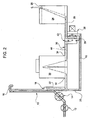
- a water supply and treatment device for a dishwashing machine includes ( Figs. 1 and 2 ) a supply line 10 on which a filling valve 12 and a flowmeter 14 are mounted and which has situated thereafter a blow-off section 16. Downstream of the latter, the line 10 has a branch-off point 18 towards a first branch and a second branch 20, 22.
- the device also comprises a first tank 24 for containing substances with water-softening properties, having an inlet opening 26 for water to be softened and an outlet opening 28 for softened water, and a second salt-containing tank 30 having a water inlet opening 32 and an outlet opening 34 for a regeneration brine formed following dissolving of the salt in the water.
- a line 36 connects the second tank 30 to the first tank 24 so that the brine formed in the second tank 30 can flow out towards the first tank 24.
- the first branch 20 of the supply line 10 leads into the connection line 36, while the second branch 22 leads to the inlet opening 32 of the second tank 30.
- a valve 38 in particular an electric valve with a shutter element 39, is arranged at the convergence point 40 of the first branch 20 and the connection line 36.
- the valve 38 is of the three-way type and allows selectively one path to be excluded from the connection with the other two paths which act as inlet and outlet, respectively, and the three paths to be connected so that two paths act as inlets and the remaining path acts as an outlet, as will be described in greater detail below.
- the valve 38 is de-energized, while, in the condition ( Fig. 2 ) where the three paths are connected together, the valve 38 is energized.
- the shutter element 39 must not perform any hydraulic sealing function. This is particular advantageous since, in the energized condition, the shutter element 39 is subject to vibrations, making it difficult to ensure effectively a hydraulic seal without having to adopt a complex and costly valve structure.
- the device may be formed by a first portion comprising the tanks 24, 30 and the supply line part 10 downstream of the blow-off section 16, and by a second portion comprising the upstream part of the supply line 10 including the blow-off section 16. Between the first and the second portion, it is thus required to provide a single hydraulic connection which ensures the continuity of the supply line 10.
- valve 38 assumes a first operating configuration where it prevents the outflow from the supply line 10 towards the first tank 24 via the second branch 22, the second tank 30 and the connection line 36, while it allows the flow inside the first branch 20 towards the first tank 24. In this way, all the water supplied to the branch-off point 18 is diverted directly (i.e. without passing through the second tank 30) into the first tank 24, where it is softened (cf. arrow 42).
- the valve 38 assumes a second operating configuration where it allows both outflow from the supply line 10 towards the first tank 24 via the second branch 22, the second tank 30 and the connection line 36 and the flow inside the first branch 20 towards the first tank 24.
- the water supplied is diverted into the first tank 24 partly (cf. arrow 42) directly and partly (cf. arrow 44) via the second tank 30, where it forms a brine which, passing subsequently through the first tank 24, regenerates the water-softening substances.
- valve 38 In the second operating configuration, it is possible to regulate the valve 38, varying for example the position of the shutter element 39 and the outflow apertures, so as to adjust in the desired manner the ratio between the fractions of water diverted into the first tank 24 directly and via the second tank 30. It is obvious in fact that the more water is diverted into the first tank 24, the more the brine is diluted.
- the filling valve 12 is of the adjustable type, it is also possible to vary the total flowrate of the water supplied depending on the operating condition assumed by the valve 38. In particular, it is convenient to reduce the total flowrate of the water during regeneration, so as to avoid the risk of an abnormal pressure increase inside the salt tank 30. When performing this adjustment, it is necessary to take into account the measurement data supplied by the flowmeter 14.
- valve 38 moreover prevents backflow along the connection line 36 from the first tank 24 towards the second tank 30.
- an additional non-return valve must be necessarily provided along the corresponding connection line of the device described in WO-2005/060 817 . Consequently, the device according to the invention may dispense with this non-return valve, being even simpler and less costly than the known valve.
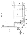
- FIGS 3 and 4 show an alternative embodiment of the device according to the invention, in which the same or equivalent parts are indicated by the same numbers used in the previous figures.
- valve 38 which is now located at the branch-off point 18 of the supply line 10, while the first branch 20 of the line 10 leads to the inlet opening 26 of the first tank 24, instead of to connection line 36.
- the valve 38 is still of the three-way type and allows one path to be excluded selectively from the connection with the other two paths which act as inlet and outlet, respectively, and the three paths to be connected together. In this latter case, however, two paths act as outlets and the remaining path acts as an inlet.
- the method of operation of the device remains substantially the same as that described above.
- the valve 38 assumes a first operating configuration where it blocks the outflow from the supply line 10 towards the first tank 24 via the second tank 30, preventing the flow of water into the second branch 22. At the same time, the valve 38 allows the flow along the first branch 20 towards the first tank 24 such that all the water supplied to the branch-off point 18 is diverted (cf. arrow 42) directly into the first tank 24, where it is softened.
- valve 38 assumes a second operating configuration where it allows both the outflow from the supply line 10 towards the first tank 24 via the second branch 22 and the second tank 30 and the flow along the first branch 20 towards the first tank 24.
- the water supplied is thus diverted into the first tank 24 partly (cf. arrow 42) directly and partly (cf. arrow 44) via the second tank 30, where it forms a brine which, passing subsequently through the first tank 24, regenerates the water-softening substances.
- FIG. 5 shows a variation of embodiment of the device according to the invention described above, in which the same or equivalent parts are indicated by the same numbers used in the previous figures.
- the only difference with respect to the device shown in Figures 3 and 4 consists in the additional presence of a non-return valve 46 along the connection line 36.
- the valve 46 allows only the flow from the second tank 30 towards the first tank 24 and thus prevents, during the water-softening treatment, the water being able to flow from the first tank 24 towards the second tank 30, preventing the risk of abnormal pressure increases inside the latter.
- the structure of the device and its method of operation are similar to those of the device shown in Figures 3 and 4 .
- the opening time of the filling valve 12 is determined on the basis of a water flowrate which is not measured directly, but is calculated taking into account the filling time envisaged for the dishwashing machine.
Claims (14)
- Dispositif pour alimenter et traiter l'eau pour un lave-vaisselle, comprenant :un premier réservoir (24) pour contenir des substances avec des propriétés d'adoucissement de l'eau, ayant au moins une ouverture d'entrée (26) pour l'eau à adoucir et une ouverture de sortie (28) pour l'eau adoucie ;un second réservoir (30) contenant du sel, ayant au moins une ouverture d'entrée d'eau (32) et une ouverture de sortie (34) pour une saumure de régénération formée suite à la dissolution du sel dans l'eau,une conduite (36) raccordant le second réservoir (30) au premier réservoir (24) de sorte que la saumure formée dans le second réservoir (30) peut s'écouler vers le premier réservoir (24), etune conduite d'alimentation d'eau (10) ayant un premier point de bifurcation (18) dans une première ramification (20) alimentant le premier réservoir (24) et dans une seconde ramification (22) qui conduit jusqu'à l'ouverture d'entrée (32) du second réservoir (30),ledit dispositif étant caractérisé en ce qu'il comprend une vanne (38) située au niveau dudit point de bifurcation (18) ou à un point de convergence (40) de ladite première ramification (20) et de ladite conduite de raccordement (36), ladite vanne (38) pouvant prendre une première configuration de fonctionnement dans laquelle elle empêche l'écoulement de la conduite d'alimentation (18) vers le premier réservoir (24) via le second réservoir (30), alors qu'elle permet l'écoulement le long de la première ramification (20) vers le premier réservoir (24), de sorte que toute l'eau alimentée au point de bifurcation (18) est déviée directement dans le premier réservoir (24), et une seconde configuration de fonctionnement dans laquelle elle permet à la fois l'écoulement de la conduite d'alimentation (10) dans le premier réservoir (24) via le second réservoir (30) et l'écoulement le long de la première ramification (20) vers le premier réservoir (24), de sorte que l'eau alimentée est déviée dans le premier réservoir (24), partiellement directement et partiellement via le second réservoir (30).
- Dispositif selon la revendication 1, caractérisé en ce que ladite vanne (38) est du type à trois voies et permet sélectivement à une trajectoire d'être exclue du raccordement avec les deux autres trajectoires qui servent d'entrée et de sortie, respectivement, et des trois trajectoires à raccorder de sorte que deux servent d'entrées / sorties et la trajectoire restante sert de sortie / entrée.
- Dispositif selon la revendication 2, caractérisé en ce que ladite vanne (38) est une vanne électrique qui, à l'état alimenté, raccorde les trois trajectoires sans que l'élément d'obturateur (39) associé doive réaliser une fonction d'étanchéité hydraulique.
- Dispositif selon l'une quelconque des revendications précédentes, caractérisé en ce que la conduite d'alimentation (10) comprend, en amont du point de bifurcation (18), une section de purge (16).
- Dispositif selon la revendication 4, caractérisé en ce qu'il est formé par une première partie comprenant lesdits réservoirs (24, 30) et la partie de la conduite d'alimentation (10) en aval de la section de purge (16) et par une seconde partie comprenant la partie en amont de la conduite d'alimentation (10) qui comprend la section de purge (16), entre lesdites première et seconde parties, il existe un raccordement hydraulique simple qui garantit la continuité de la conduite d'alimentation (10).
- Dispositif selon la revendication 4 ou 5, caractérisé en ce qu'une vanne de remplissage (12) et un débitmètre (14) sont montés sur ladite conduite d'alimentation (10), en amont de la section de purge (16).
- Dispositif selon la revendication 6, caractérisé en ce que la vanne de remplissage (12) peut être ajustée afin de permettre la variation du débit total de l'eau alimentée en fonction de la configuration de fonctionnement prise par ladite vanne à trois voies (38).
- Dispositif selon la revendication 7, caractérisé en ce que l'ajustement de la vanne de remplissage (12) est réalisé en prenant en compte les mesures réalisées par ledit débitmètre (14).
- Dispositif selon l'une quelconque des revendications 4 ou 5, caractérisé en ce qu'une vanne de remplissage (12) est montée sur la section de ladite conduite d'alimentation (10) en amont de ladite section de purge (16), alors qu'aucun débitmètre n'est monté à cet endroit-là, de sorte que le temps d'ouverture de ladite vanne (12) est déterminé en fonction d'un débit d'eau calculé en utilisant le temps de remplissage envisagé pour le lave-vaisselle.
- Dispositif selon l'une quelconque des revendications précédentes, caractérisé en ce que, dans ladite seconde configuration de fonctionnement de la vanne (38), le rapport entre les fractions d'eau déviées dans le premier réservoir (24) directement et via le second réservoir (30) est ajustable.
- Dispositif selon l'une quelconque des revendications précédentes, caractérisé en ce que ladite première ramification (20) de ladite conduite d'alimentation (10) conduit dans ladite conduite de raccordement (36) et ladite vanne (38) est située au point de convergence de ladite première ramification (20) et de ladite conduite de raccordement (36).
- Dispositif selon l'une quelconque des revendications 1 à 10 précédentes, caractérisé en ce que ladite première ramification (20) de la conduite d'alimentation (10) conduit à l'ouverture d'entrée (26) du premier réservoir (24) et ladite vanne (38) est située au niveau dudit point de bifurcation (18) de la conduite d'alimentation (10).
- Lave-vaisselle comprenant un dispositif selon l'une quelconque des revendications précédentes, dans lequel la vanne (38) prend, pendant l'étape d'alimentation d'eau, ladite première configuration de fonctionnement et pendant la seconde étape pour la régénération des substances d'adoucissement d'eau, ladite seconde configuration de fonctionnement.
- Lave-vaisselle selon la revendication 13, dans lequel ledit dispositif comprend une vanne de remplissage (12) qui est alimentée à la fois pendant l'étape d'alimentation d'eau et pendant l'étape de régénération et pendant lesdites deux étapes au moins une partie de l'eau s'écoule vers le premier réservoir (24) sans passer par le second réservoir (30).
Priority Applications (1)
| Application Number | Priority Date | Filing Date | Title |
|---|---|---|---|
| PL07103564T PL1844693T3 (pl) | 2006-03-07 | 2007-03-06 | Ulepszone urządzenie do dostarczania i uzdatniania wody dla zmywarki do naczyń |
Applications Claiming Priority (1)
| Application Number | Priority Date | Filing Date | Title |
|---|---|---|---|
| IT000165A ITTO20060165A1 (it) | 2006-03-07 | 2006-03-07 | Dispositivo perfezionato di alimentazione e trattamento di acqua per macchina lavastoviglie. |
Publications (2)
| Publication Number | Publication Date |
|---|---|
| EP1844693A1 EP1844693A1 (fr) | 2007-10-17 |
| EP1844693B1 true EP1844693B1 (fr) | 2010-03-24 |
Family
ID=38292657
Family Applications (1)
| Application Number | Title | Priority Date | Filing Date |
|---|---|---|---|
| EP07103564A Active EP1844693B1 (fr) | 2006-03-07 | 2007-03-06 | Dispositif amélioré pour la fourniture et le traitement d'eau pour lave-vaisselle |
Country Status (7)
| Country | Link |
|---|---|
| EP (1) | EP1844693B1 (fr) |
| CN (1) | CN101041518B (fr) |
| AT (1) | ATE461652T1 (fr) |
| DE (1) | DE602007005413D1 (fr) |
| ES (1) | ES2343279T3 (fr) |
| IT (1) | ITTO20060165A1 (fr) |
| PL (1) | PL1844693T3 (fr) |
Cited By (1)
| Publication number | Priority date | Publication date | Assignee | Title |
|---|---|---|---|---|
| US10646098B2 (en) | 2015-06-19 | 2020-05-12 | Bitron S.P.A. | Integrated component for a dishwashing machine |
Families Citing this family (10)
| Publication number | Priority date | Publication date | Assignee | Title |
|---|---|---|---|---|
| DE102007052085A1 (de) | 2007-10-31 | 2009-05-07 | BSH Bosch und Siemens Hausgeräte GmbH | Verfahren zum Betreiben eines wasserführendes Haushaltsgeräts |
| CN102462473B (zh) * | 2010-11-18 | 2014-05-28 | 比亚迪股份有限公司 | 洗碗机及其供水装置 |
| ITTO20110775A1 (it) | 2011-08-25 | 2013-02-26 | Bitron Spa | Dispositivo decalcificatore perfezionato |
| ITTO20110787A1 (it) * | 2011-09-02 | 2013-03-03 | Bitron Spa | Dispositivo decalcificatore con rigenerazione a circuito chiuso |
| ES2633591T3 (es) | 2011-12-13 | 2017-09-22 | Ecolab Usa Inc. | Método de separación de sustancias químicas en un lavavajillas |
| KR20130087858A (ko) * | 2012-01-30 | 2013-08-07 | 삼성전자주식회사 | 연수화 장치 및 이를 포함하는 식기세척기 |
| ITTO20130338A1 (it) * | 2013-04-24 | 2014-10-25 | Bitron Spa | Sistema di alimentazione e trattamento di acqua per una macchina lavatrice, in particolare una macchina lavastoviglie |
| DE202015007584U1 (de) | 2014-11-03 | 2016-02-15 | Bitron S.P.A. | Verbesserter Wasserenthärtungskreislauf für ein Wasserbearbeitungssystem für eine Waschmaschine/Geschirrspüler und eine Maschine hierfür |
| KR102543237B1 (ko) * | 2015-06-19 | 2023-06-13 | 비트론 에스.피.에이. | 식기세척기 |
| ES2702491A1 (es) * | 2017-09-01 | 2019-03-01 | Bsh Electrodomesticos Espana Sa | Máquina lavavajillas doméstica con disposición de tanque |
Family Cites Families (2)
| Publication number | Priority date | Publication date | Assignee | Title |
|---|---|---|---|---|
| PL1701647T3 (pl) * | 2003-12-22 | 2012-10-31 | Bsh Hausgeraete Gmbh | Zmywarka do naczyń z systemem zmiękczania wody |
| ITTO20050805A1 (it) * | 2005-11-15 | 2007-05-16 | T & P Spa | Sistema per abbattere la durezza dell'acqua di lavaggio in una macchina di lavaggio in particolare una lavastoviglie e relativo metodo |
-
2006
- 2006-03-07 IT IT000165A patent/ITTO20060165A1/it unknown
-
2007
- 2007-03-06 PL PL07103564T patent/PL1844693T3/pl unknown
- 2007-03-06 AT AT07103564T patent/ATE461652T1/de not_active IP Right Cessation
- 2007-03-06 EP EP07103564A patent/EP1844693B1/fr active Active
- 2007-03-06 DE DE602007005413T patent/DE602007005413D1/de active Active
- 2007-03-06 ES ES07103564T patent/ES2343279T3/es active Active
- 2007-03-07 CN CN2007100855194A patent/CN101041518B/zh active Active
Cited By (1)
| Publication number | Priority date | Publication date | Assignee | Title |
|---|---|---|---|---|
| US10646098B2 (en) | 2015-06-19 | 2020-05-12 | Bitron S.P.A. | Integrated component for a dishwashing machine |
Also Published As
| Publication number | Publication date |
|---|---|
| CN101041518A (zh) | 2007-09-26 |
| CN101041518B (zh) | 2011-08-03 |
| ES2343279T3 (es) | 2010-07-27 |
| EP1844693A1 (fr) | 2007-10-17 |
| ITTO20060165A1 (it) | 2007-09-08 |
| DE602007005413D1 (de) | 2010-05-06 |
| PL1844693T3 (pl) | 2010-08-31 |
| ATE461652T1 (de) | 2010-04-15 |
Similar Documents
| Publication | Publication Date | Title |
|---|---|---|
| EP1844693B1 (fr) | Dispositif amélioré pour la fourniture et le traitement d'eau pour lave-vaisselle | |
| EP2561790B1 (fr) | Dispositif adoucisseur amélioré | |
| CN104582547A (zh) | 为饮料机提供液体的装置及其用法 | |
| US5893976A (en) | Method for treatment of water | |
| US9908159B2 (en) | Washing device for water treatment apparatus and washing method thereof | |
| CN104324549A (zh) | 一种管道净水机的冲洗系统及控制方法 | |
| KR102581407B1 (ko) | 재생통, 냉수 탱크 및 온수 탱크를 연결하는 커넥터를 포함하는 연수기 및 그 제어 방법 | |
| CN105338873A (zh) | 用于洗涤机、特别是洗碗机的用于供应和处理的水的系统 | |
| EP2988650A1 (fr) | Système d'alimentation et de traitement de l'eau pour un lave-vaisselle | |
| CN104713221A (zh) | 电热水器 | |
| ES2637486T3 (es) | Lavavajillas con una instalación de tratamiento de agua | |
| EP2044876B1 (fr) | Lave-vaisselle doté d'un système intégré pour contrôler des quantités d'eau | |
| CN103764896A (zh) | 具有虹吸管的带水运行的家用器具 | |
| EP1841344B1 (fr) | Procede de commande et de gestion de debit d'eau vers une machine a cafe pourvue d'un dispositif adoucisseur d'eau de type resine echangeuse d'ions, et machine a cafe permettant de mettre en oeuvre ledit procede | |
| KR101109014B1 (ko) | 자동역세척이 가능한 배관연결체 | |
| JP4876714B2 (ja) | 充填システムの洗浄装置 | |
| EP1582135A1 (fr) | Dispositif pour contrôler la dureté de l'eau dans une machine à laver ou une lave-vaisselle | |
| EP0565876B1 (fr) | Méthode pour régénérer des adoucisseurs d'eau et adoucisseur d'eau | |
| GB2362114A (en) | Flow controlled regeneration of water treatment apparatus | |
| JP4419178B2 (ja) | 軟水器における排水工程の制御方法 | |
| CN109276214B (zh) | 用于清洁家居用品的家用电器 | |
| EP3567010B1 (fr) | Appareil adoucisseur d'eau | |
| JP2009125641A (ja) | 軟水装置の運転制御システム | |
| JPH059114Y2 (fr) | ||
| JP3580191B2 (ja) | ボイラ |
Legal Events
| Date | Code | Title | Description |
|---|---|---|---|
| PUAI | Public reference made under article 153(3) epc to a published international application that has entered the european phase |
Free format text: ORIGINAL CODE: 0009012 |
|
| AK | Designated contracting states |
Kind code of ref document: A1 Designated state(s): AT BE BG CH CY CZ DE DK EE ES FI FR GB GR HU IE IS IT LI LT LU LV MC MT NL PL PT RO SE SI SK TR |
|
| AX | Request for extension of the european patent |
Extension state: AL BA HR MK YU |
|
| 17P | Request for examination filed |
Effective date: 20080314 |
|
| AKX | Designation fees paid |
Designated state(s): AT BE BG CH CY CZ DE DK EE ES FI FR GB GR HU IE IS IT LI LT LU LV MC MT NL PL PT RO SE SI SK TR |
|
| GRAP | Despatch of communication of intention to grant a patent |
Free format text: ORIGINAL CODE: EPIDOSNIGR1 |
|
| GRAS | Grant fee paid |
Free format text: ORIGINAL CODE: EPIDOSNIGR3 |
|
| GRAA | (expected) grant |
Free format text: ORIGINAL CODE: 0009210 |
|
| AK | Designated contracting states |
Kind code of ref document: B1 Designated state(s): AT BE BG CH CY CZ DE DK EE ES FI FR GB GR HU IE IS IT LI LT LU LV MC MT NL PL PT RO SE SI SK TR |
|
| REG | Reference to a national code |
Ref country code: GB Ref legal event code: FG4D |
|
| REG | Reference to a national code |
Ref country code: CH Ref legal event code: EP |
|
| REG | Reference to a national code |
Ref country code: IE Ref legal event code: FG4D |
|
| REF | Corresponds to: |
Ref document number: 602007005413 Country of ref document: DE Date of ref document: 20100506 Kind code of ref document: P |
|
| REG | Reference to a national code |
Ref country code: NL Ref legal event code: VDEP Effective date: 20100324 |
|
| REG | Reference to a national code |
Ref country code: ES Ref legal event code: FG2A Ref document number: 2343279 Country of ref document: ES Kind code of ref document: T3 |
|
| PG25 | Lapsed in a contracting state [announced via postgrant information from national office to epo] |
Ref country code: LT Free format text: LAPSE BECAUSE OF FAILURE TO SUBMIT A TRANSLATION OF THE DESCRIPTION OR TO PAY THE FEE WITHIN THE PRESCRIBED TIME-LIMIT Effective date: 20100324 |
|
| LTIE | Lt: invalidation of european patent or patent extension |
Effective date: 20100324 |
|
| PG25 | Lapsed in a contracting state [announced via postgrant information from national office to epo] |
Ref country code: SI Free format text: LAPSE BECAUSE OF FAILURE TO SUBMIT A TRANSLATION OF THE DESCRIPTION OR TO PAY THE FEE WITHIN THE PRESCRIBED TIME-LIMIT Effective date: 20100324 Ref country code: FI Free format text: LAPSE BECAUSE OF FAILURE TO SUBMIT A TRANSLATION OF THE DESCRIPTION OR TO PAY THE FEE WITHIN THE PRESCRIBED TIME-LIMIT Effective date: 20100324 Ref country code: AT Free format text: LAPSE BECAUSE OF FAILURE TO SUBMIT A TRANSLATION OF THE DESCRIPTION OR TO PAY THE FEE WITHIN THE PRESCRIBED TIME-LIMIT Effective date: 20100324 Ref country code: LV Free format text: LAPSE BECAUSE OF FAILURE TO SUBMIT A TRANSLATION OF THE DESCRIPTION OR TO PAY THE FEE WITHIN THE PRESCRIBED TIME-LIMIT Effective date: 20100324 |
|
| REG | Reference to a national code |
Ref country code: PL Ref legal event code: T3 |
|
| PG25 | Lapsed in a contracting state [announced via postgrant information from national office to epo] |
Ref country code: GR Free format text: LAPSE BECAUSE OF FAILURE TO SUBMIT A TRANSLATION OF THE DESCRIPTION OR TO PAY THE FEE WITHIN THE PRESCRIBED TIME-LIMIT Effective date: 20100625 Ref country code: NL Free format text: LAPSE BECAUSE OF FAILURE TO SUBMIT A TRANSLATION OF THE DESCRIPTION OR TO PAY THE FEE WITHIN THE PRESCRIBED TIME-LIMIT Effective date: 20100324 Ref country code: BE Free format text: LAPSE BECAUSE OF FAILURE TO SUBMIT A TRANSLATION OF THE DESCRIPTION OR TO PAY THE FEE WITHIN THE PRESCRIBED TIME-LIMIT Effective date: 20100324 Ref country code: SE Free format text: LAPSE BECAUSE OF FAILURE TO SUBMIT A TRANSLATION OF THE DESCRIPTION OR TO PAY THE FEE WITHIN THE PRESCRIBED TIME-LIMIT Effective date: 20100324 Ref country code: RO Free format text: LAPSE BECAUSE OF FAILURE TO SUBMIT A TRANSLATION OF THE DESCRIPTION OR TO PAY THE FEE WITHIN THE PRESCRIBED TIME-LIMIT Effective date: 20100324 Ref country code: EE Free format text: LAPSE BECAUSE OF FAILURE TO SUBMIT A TRANSLATION OF THE DESCRIPTION OR TO PAY THE FEE WITHIN THE PRESCRIBED TIME-LIMIT Effective date: 20100324 |
|
| PG25 | Lapsed in a contracting state [announced via postgrant information from national office to epo] |
Ref country code: BG Free format text: LAPSE BECAUSE OF FAILURE TO SUBMIT A TRANSLATION OF THE DESCRIPTION OR TO PAY THE FEE WITHIN THE PRESCRIBED TIME-LIMIT Effective date: 20100624 Ref country code: IS Free format text: LAPSE BECAUSE OF FAILURE TO SUBMIT A TRANSLATION OF THE DESCRIPTION OR TO PAY THE FEE WITHIN THE PRESCRIBED TIME-LIMIT Effective date: 20100724 Ref country code: SK Free format text: LAPSE BECAUSE OF FAILURE TO SUBMIT A TRANSLATION OF THE DESCRIPTION OR TO PAY THE FEE WITHIN THE PRESCRIBED TIME-LIMIT Effective date: 20100324 Ref country code: CZ Free format text: LAPSE BECAUSE OF FAILURE TO SUBMIT A TRANSLATION OF THE DESCRIPTION OR TO PAY THE FEE WITHIN THE PRESCRIBED TIME-LIMIT Effective date: 20100324 |
|
| PLBE | No opposition filed within time limit |
Free format text: ORIGINAL CODE: 0009261 |
|
| STAA | Information on the status of an ep patent application or granted ep patent |
Free format text: STATUS: NO OPPOSITION FILED WITHIN TIME LIMIT |
|
| PG25 | Lapsed in a contracting state [announced via postgrant information from national office to epo] |
Ref country code: PT Free format text: LAPSE BECAUSE OF FAILURE TO SUBMIT A TRANSLATION OF THE DESCRIPTION OR TO PAY THE FEE WITHIN THE PRESCRIBED TIME-LIMIT Effective date: 20100726 Ref country code: DK Free format text: LAPSE BECAUSE OF FAILURE TO SUBMIT A TRANSLATION OF THE DESCRIPTION OR TO PAY THE FEE WITHIN THE PRESCRIBED TIME-LIMIT Effective date: 20100324 |
|
| 26N | No opposition filed |
Effective date: 20101228 |
|
| PG25 | Lapsed in a contracting state [announced via postgrant information from national office to epo] |
Ref country code: MC Free format text: LAPSE BECAUSE OF NON-PAYMENT OF DUE FEES Effective date: 20110331 |
|
| REG | Reference to a national code |
Ref country code: CH Ref legal event code: PL |
|
| GBPC | Gb: european patent ceased through non-payment of renewal fee |
Effective date: 20110306 |
|
| PG25 | Lapsed in a contracting state [announced via postgrant information from national office to epo] |
Ref country code: MT Free format text: LAPSE BECAUSE OF FAILURE TO SUBMIT A TRANSLATION OF THE DESCRIPTION OR TO PAY THE FEE WITHIN THE PRESCRIBED TIME-LIMIT Effective date: 20100324 |
|
| REG | Reference to a national code |
Ref country code: IE Ref legal event code: MM4A |
|
| PG25 | Lapsed in a contracting state [announced via postgrant information from national office to epo] |
Ref country code: IE Free format text: LAPSE BECAUSE OF NON-PAYMENT OF DUE FEES Effective date: 20110306 Ref country code: LI Free format text: LAPSE BECAUSE OF NON-PAYMENT OF DUE FEES Effective date: 20110331 Ref country code: CH Free format text: LAPSE BECAUSE OF NON-PAYMENT OF DUE FEES Effective date: 20110331 |
|
| PG25 | Lapsed in a contracting state [announced via postgrant information from national office to epo] |
Ref country code: GB Free format text: LAPSE BECAUSE OF NON-PAYMENT OF DUE FEES Effective date: 20110306 |
|
| PG25 | Lapsed in a contracting state [announced via postgrant information from national office to epo] |
Ref country code: LU Free format text: LAPSE BECAUSE OF NON-PAYMENT OF DUE FEES Effective date: 20110306 Ref country code: CY Free format text: LAPSE BECAUSE OF FAILURE TO SUBMIT A TRANSLATION OF THE DESCRIPTION OR TO PAY THE FEE WITHIN THE PRESCRIBED TIME-LIMIT Effective date: 20100324 |
|
| PG25 | Lapsed in a contracting state [announced via postgrant information from national office to epo] |
Ref country code: HU Free format text: LAPSE BECAUSE OF FAILURE TO SUBMIT A TRANSLATION OF THE DESCRIPTION OR TO PAY THE FEE WITHIN THE PRESCRIBED TIME-LIMIT Effective date: 20100324 |
|
| REG | Reference to a national code |
Ref country code: FR Ref legal event code: PLFP Year of fee payment: 10 |
|
| REG | Reference to a national code |
Ref country code: FR Ref legal event code: PLFP Year of fee payment: 11 |
|
| REG | Reference to a national code |
Ref country code: FR Ref legal event code: PLFP Year of fee payment: 12 |
|
| PGFP | Annual fee paid to national office [announced via postgrant information from national office to epo] |
Ref country code: FR Payment date: 20230320 Year of fee payment: 17 |
|
| PGFP | Annual fee paid to national office [announced via postgrant information from national office to epo] |
Ref country code: TR Payment date: 20230306 Year of fee payment: 17 Ref country code: PL Payment date: 20230124 Year of fee payment: 17 Ref country code: IT Payment date: 20230203 Year of fee payment: 17 |
|
| P01 | Opt-out of the competence of the unified patent court (upc) registered |
Effective date: 20230527 |
|
| PGFP | Annual fee paid to national office [announced via postgrant information from national office to epo] |
Ref country code: ES Payment date: 20230403 Year of fee payment: 17 |
|
| PGFP | Annual fee paid to national office [announced via postgrant information from national office to epo] |
Ref country code: DE Payment date: 20240320 Year of fee payment: 18 |