EP1844693B1 - Improved device for supplying and treating water for a dishwashing machine - Google Patents
Improved device for supplying and treating water for a dishwashing machine Download PDFInfo
- Publication number
- EP1844693B1 EP1844693B1 EP07103564A EP07103564A EP1844693B1 EP 1844693 B1 EP1844693 B1 EP 1844693B1 EP 07103564 A EP07103564 A EP 07103564A EP 07103564 A EP07103564 A EP 07103564A EP 1844693 B1 EP1844693 B1 EP 1844693B1
- Authority
- EP
- European Patent Office
- Prior art keywords
- tank
- water
- branch
- valve
- supply line
- Prior art date
- Legal status (The legal status is an assumption and is not a legal conclusion. Google has not performed a legal analysis and makes no representation as to the accuracy of the status listed.)
- Active
Links
Images


Classifications
-
- A—HUMAN NECESSITIES
- A47—FURNITURE; DOMESTIC ARTICLES OR APPLIANCES; COFFEE MILLS; SPICE MILLS; SUCTION CLEANERS IN GENERAL
- A47L—DOMESTIC WASHING OR CLEANING; SUCTION CLEANERS IN GENERAL
- A47L15/00—Washing or rinsing machines for crockery or tableware
- A47L15/42—Details
- A47L15/4229—Water softening arrangements
-
- B—PERFORMING OPERATIONS; TRANSPORTING
- B65—CONVEYING; PACKING; STORING; HANDLING THIN OR FILAMENTARY MATERIAL
- B65D—CONTAINERS FOR STORAGE OR TRANSPORT OF ARTICLES OR MATERIALS, e.g. BAGS, BARRELS, BOTTLES, BOXES, CANS, CARTONS, CRATES, DRUMS, JARS, TANKS, HOPPERS, FORWARDING CONTAINERS; ACCESSORIES, CLOSURES, OR FITTINGS THEREFOR; PACKAGING ELEMENTS; PACKAGES
- B65D81/00—Containers, packaging elements, or packages, for contents presenting particular transport or storage problems, or adapted to be used for non-packaging purposes after removal of contents
- B65D81/32—Containers, packaging elements, or packages, for contents presenting particular transport or storage problems, or adapted to be used for non-packaging purposes after removal of contents for packaging two or more different materials which must be maintained separate prior to use in admixture
- B65D81/3294—Thermoformed trays or the like with a plurality of recesses for different materials located in different recesses
-
- B—PERFORMING OPERATIONS; TRANSPORTING
- B65—CONVEYING; PACKING; STORING; HANDLING THIN OR FILAMENTARY MATERIAL
- B65D—CONTAINERS FOR STORAGE OR TRANSPORT OF ARTICLES OR MATERIALS, e.g. BAGS, BARRELS, BOTTLES, BOXES, CANS, CARTONS, CRATES, DRUMS, JARS, TANKS, HOPPERS, FORWARDING CONTAINERS; ACCESSORIES, CLOSURES, OR FITTINGS THEREFOR; PACKAGING ELEMENTS; PACKAGES
- B65D85/00—Containers, packaging elements or packages, specially adapted for particular articles or materials
- B65D85/70—Containers, packaging elements or packages, specially adapted for particular articles or materials for materials not otherwise provided for
- B65D85/72—Containers, packaging elements or packages, specially adapted for particular articles or materials for materials not otherwise provided for for edible or potable liquids, semiliquids, or plastic or pasty materials
- B65D85/78—Containers, packaging elements or packages, specially adapted for particular articles or materials for materials not otherwise provided for for edible or potable liquids, semiliquids, or plastic or pasty materials for ice-cream
Definitions
- the present invention relates to a device for supplying and treating water for a dishwashing machine.
- this device comprises:
- a device of this kind is described in the PCT patent application WO-2005/060 817 .
- This known device comprises a divertor which is situated at the branch-off point for the two branches of the supply line and allows directing of the water supplied alternately into the first or the second tank.
- the water passes through the water-softening substances and is softened so that it can then be introduced into the washing chamber of the dishwashing machine, without the formation of damaging deposits and the like.
- said operation In the second case, relating instead to the regenerating stage, said operation must be performed periodically in order to reactivate the water-softening substances.
- the brine formed in the second tank is subsequently made to pass through the water-softening substances, which are typically ion-exchange resins contained in the first tank, and are thus regenerated.
- the object of the present invention is to provide a device for supplying and treating water for a dishwashing machine which is improved compared to known devices and which in particular does not pose the problem mentioned above.
- this object is achieved by means of a device of the type indicated at the start of the present description and characterized in that it comprises a valve situated at said branch-off point or a converging point of said first branch and said connection line, said valve being able to assume a first operating configuration where it blocks the outflow from the supply line towards the first tank via the second tank, while it allows the flow along the first branch towards the first tank, so that all the water supplied to the branch-off point is diverted directly into the first tank, and a second operating configuration where it allows both the outflow from the supply line towards the first tank via the second tank and the flow along the first branch towards the first tank, so that the water supplied is diverted into the first tank partly directly and partly via the second tank.
- the device according to the invention does not require a storage vessel for the water to be supplied to the salt-containing tank.
- the valve in no operating configuration of the valve is the flow along the first branch of the supply line towards the tank containing the water-softening substances interrupted. Therefore, even in the event of obstruction of the inlet and/or outlet openings of the salt-containing tank, the water supplied to the device may in any case flow outside of it, without giving rise to dangerous overpressure.
- the regeneration step is performed supplying simultaneously both mains water and brine to the tank containing the water-softening substances.
- the brine is thus diluted with the advantage that it has a less aggressive action on the water-softening substances.
- the present invention also relates to a dishwashing machine comprising a water supply and treatment device of the type described above.
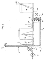
- a water supply and treatment device for a dishwashing machine includes ( Figs. 1 and 2 ) a supply line 10 on which a filling valve 12 and a flowmeter 14 are mounted and which has situated thereafter a blow-off section 16. Downstream of the latter, the line 10 has a branch-off point 18 towards a first branch and a second branch 20, 22.
- the device also comprises a first tank 24 for containing substances with water-softening properties, having an inlet opening 26 for water to be softened and an outlet opening 28 for softened water, and a second salt-containing tank 30 having a water inlet opening 32 and an outlet opening 34 for a regeneration brine formed following dissolving of the salt in the water.
- a line 36 connects the second tank 30 to the first tank 24 so that the brine formed in the second tank 30 can flow out towards the first tank 24.
- the first branch 20 of the supply line 10 leads into the connection line 36, while the second branch 22 leads to the inlet opening 32 of the second tank 30.
- a valve 38 in particular an electric valve with a shutter element 39, is arranged at the convergence point 40 of the first branch 20 and the connection line 36.
- the valve 38 is of the three-way type and allows selectively one path to be excluded from the connection with the other two paths which act as inlet and outlet, respectively, and the three paths to be connected so that two paths act as inlets and the remaining path acts as an outlet, as will be described in greater detail below.
- the valve 38 is de-energized, while, in the condition ( Fig. 2 ) where the three paths are connected together, the valve 38 is energized.
- the shutter element 39 must not perform any hydraulic sealing function. This is particular advantageous since, in the energized condition, the shutter element 39 is subject to vibrations, making it difficult to ensure effectively a hydraulic seal without having to adopt a complex and costly valve structure.
- the device may be formed by a first portion comprising the tanks 24, 30 and the supply line part 10 downstream of the blow-off section 16, and by a second portion comprising the upstream part of the supply line 10 including the blow-off section 16. Between the first and the second portion, it is thus required to provide a single hydraulic connection which ensures the continuity of the supply line 10.
- valve 38 assumes a first operating configuration where it prevents the outflow from the supply line 10 towards the first tank 24 via the second branch 22, the second tank 30 and the connection line 36, while it allows the flow inside the first branch 20 towards the first tank 24. In this way, all the water supplied to the branch-off point 18 is diverted directly (i.e. without passing through the second tank 30) into the first tank 24, where it is softened (cf. arrow 42).
- the valve 38 assumes a second operating configuration where it allows both outflow from the supply line 10 towards the first tank 24 via the second branch 22, the second tank 30 and the connection line 36 and the flow inside the first branch 20 towards the first tank 24.
- the water supplied is diverted into the first tank 24 partly (cf. arrow 42) directly and partly (cf. arrow 44) via the second tank 30, where it forms a brine which, passing subsequently through the first tank 24, regenerates the water-softening substances.
- valve 38 In the second operating configuration, it is possible to regulate the valve 38, varying for example the position of the shutter element 39 and the outflow apertures, so as to adjust in the desired manner the ratio between the fractions of water diverted into the first tank 24 directly and via the second tank 30. It is obvious in fact that the more water is diverted into the first tank 24, the more the brine is diluted.
- the filling valve 12 is of the adjustable type, it is also possible to vary the total flowrate of the water supplied depending on the operating condition assumed by the valve 38. In particular, it is convenient to reduce the total flowrate of the water during regeneration, so as to avoid the risk of an abnormal pressure increase inside the salt tank 30. When performing this adjustment, it is necessary to take into account the measurement data supplied by the flowmeter 14.
- valve 38 moreover prevents backflow along the connection line 36 from the first tank 24 towards the second tank 30.
- an additional non-return valve must be necessarily provided along the corresponding connection line of the device described in WO-2005/060 817 . Consequently, the device according to the invention may dispense with this non-return valve, being even simpler and less costly than the known valve.
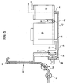
- FIGS 3 and 4 show an alternative embodiment of the device according to the invention, in which the same or equivalent parts are indicated by the same numbers used in the previous figures.
- valve 38 which is now located at the branch-off point 18 of the supply line 10, while the first branch 20 of the line 10 leads to the inlet opening 26 of the first tank 24, instead of to connection line 36.
- the valve 38 is still of the three-way type and allows one path to be excluded selectively from the connection with the other two paths which act as inlet and outlet, respectively, and the three paths to be connected together. In this latter case, however, two paths act as outlets and the remaining path acts as an inlet.
- the method of operation of the device remains substantially the same as that described above.
- the valve 38 assumes a first operating configuration where it blocks the outflow from the supply line 10 towards the first tank 24 via the second tank 30, preventing the flow of water into the second branch 22. At the same time, the valve 38 allows the flow along the first branch 20 towards the first tank 24 such that all the water supplied to the branch-off point 18 is diverted (cf. arrow 42) directly into the first tank 24, where it is softened.
- valve 38 assumes a second operating configuration where it allows both the outflow from the supply line 10 towards the first tank 24 via the second branch 22 and the second tank 30 and the flow along the first branch 20 towards the first tank 24.
- the water supplied is thus diverted into the first tank 24 partly (cf. arrow 42) directly and partly (cf. arrow 44) via the second tank 30, where it forms a brine which, passing subsequently through the first tank 24, regenerates the water-softening substances.
- FIG. 5 shows a variation of embodiment of the device according to the invention described above, in which the same or equivalent parts are indicated by the same numbers used in the previous figures.
- the only difference with respect to the device shown in Figures 3 and 4 consists in the additional presence of a non-return valve 46 along the connection line 36.
- the valve 46 allows only the flow from the second tank 30 towards the first tank 24 and thus prevents, during the water-softening treatment, the water being able to flow from the first tank 24 towards the second tank 30, preventing the risk of abnormal pressure increases inside the latter.
- the structure of the device and its method of operation are similar to those of the device shown in Figures 3 and 4 .
- the opening time of the filling valve 12 is determined on the basis of a water flowrate which is not measured directly, but is calculated taking into account the filling time envisaged for the dishwashing machine.
Abstract
Description
- The present invention relates to a device for supplying and treating water for a dishwashing machine.
- In greater detail, this device comprises:
- a first tank for containing substances with water-softening properties, having at least one inlet opening for water to be softened and an outlet opening for softened water,
- a second salt-containing tank, having at least one water inlet opening and an outlet opening for a regenerating brine formed following dissolving of the salt in the water,
- a line connecting the second tank to the first tank so that the brine formed in the second tank can flow out towards the first tank, and
- a water supply line having a first branch-off point into a first branch supplying the first tank and into a second branch which leads to the inlet opening of the second tank.
- A device of this kind is described in the PCT patent application
WO-2005/060 817 . This known device comprises a divertor which is situated at the branch-off point for the two branches of the supply line and allows directing of the water supplied alternately into the first or the second tank. In the first case, which relates to the normal operating condition, the water passes through the water-softening substances and is softened so that it can then be introduced into the washing chamber of the dishwashing machine, without the formation of damaging deposits and the like. In the second case, relating instead to the regenerating stage, said operation must be performed periodically in order to reactivate the water-softening substances. In this case, the brine formed in the second tank is subsequently made to pass through the water-softening substances, which are typically ion-exchange resins contained in the first tank, and are thus regenerated. - In the known device described above, owing to the presence of the divertor, all the water supplied is, in each case, diverted directly into the tank containing the ion-exchange resins or into the salt-containing tank and from here into the tank containing these resins. As a result, it is possible to dispense with a storage vessel for the water to be supplied to the salt-containing tank, which is instead typically present in most conventional water supplying and treatment devices. Consequently, the overall structure of the device described in
WO-2005/060 817 is simplified. Moreover, the overall volume of this device is reduced and the space thus saved may be occupied by other components of the dishwashing machine. - However, causing the entire flow of water supplied to the device to flow out through the salt tank may result in damaging overpressure, due for example to grains of salt getting stuck in the narrow slits which form the inlet and outlet openings of the second tank, with the risk of completely preventing the water flowing out through the device.
- The object of the present invention is to provide a device for supplying and treating water for a dishwashing machine which is improved compared to known devices and which in particular does not pose the problem mentioned above.
- According to the invention, this object is achieved by means of a device of the type indicated at the start of the present description and characterized in that it comprises a valve situated at said branch-off point or a converging point of said first branch and said connection line, said valve being able to assume a first operating configuration where it blocks the outflow from the supply line towards the first tank via the second tank, while it allows the flow along the first branch towards the first tank, so that all the water supplied to the branch-off point is diverted directly into the first tank, and a second operating configuration where it allows both the outflow from the supply line towards the first tank via the second tank and the flow along the first branch towards the first tank, so that the water supplied is diverted into the first tank partly directly and partly via the second tank.
- Owing to the presence of the valve and its position, the device according to the invention does not require a storage vessel for the water to be supplied to the salt-containing tank. At the same time, in no operating configuration of the valve is the flow along the first branch of the supply line towards the tank containing the water-softening substances interrupted. Therefore, even in the event of obstruction of the inlet and/or outlet openings of the salt-containing tank, the water supplied to the device may in any case flow outside of it, without giving rise to dangerous overpressure.
- Moreover, in the device according to the invention, the regeneration step is performed supplying simultaneously both mains water and brine to the tank containing the water-softening substances. The brine is thus diluted with the advantage that it has a less aggressive action on the water-softening substances.
- The present invention also relates to a dishwashing machine comprising a water supply and treatment device of the type described above.
- Further advantages and characteristic features of the present invention will become clear from the detailed description which follows, provided with reference to the accompanying drawings provided by way of a non-limiting example, in which:
-
Figure 1 is a schematic view of a device according to the invention during the water-softening treatment step, -
Figure 2 is a schematic illustration of the device according toFigure 1 during the regeneration step, -
Figures 3 and4 are schematic illustrations, corresponding toFigures 1 and2 , respectively, of a second embodiment of the device according to the invention, and -
Figure 5 is a schematic illustration, corresponding to that ofFigure 3 , of a variant of the second embodiment of the device according to the invention. - A water supply and treatment device for a dishwashing machine includes (
Figs. 1 and2 ) asupply line 10 on which afilling valve 12 and aflowmeter 14 are mounted and which has situated thereafter a blow-offsection 16. Downstream of the latter, theline 10 has a branch-offpoint 18 towards a first branch and asecond branch - The device also comprises a
first tank 24 for containing substances with water-softening properties, having an inlet opening 26 for water to be softened and an outlet opening 28 for softened water, and a second salt-containingtank 30 having a water inlet opening 32 and an outlet opening 34 for a regeneration brine formed following dissolving of the salt in the water. Aline 36 connects thesecond tank 30 to thefirst tank 24 so that the brine formed in thesecond tank 30 can flow out towards thefirst tank 24. - The
first branch 20 of thesupply line 10 leads into theconnection line 36, while thesecond branch 22 leads to the inlet opening 32 of thesecond tank 30. Avalve 38, in particular an electric valve with ashutter element 39, is arranged at theconvergence point 40 of thefirst branch 20 and theconnection line 36. Thevalve 38 is of the three-way type and allows selectively one path to be excluded from the connection with the other two paths which act as inlet and outlet, respectively, and the three paths to be connected so that two paths act as inlets and the remaining path acts as an outlet, as will be described in greater detail below. - Preferably, in the condition (
Fig. 1 ) where one path is excluded from connection with the other two, thevalve 38 is de-energized, while, in the condition (Fig. 2 ) where the three paths are connected together, thevalve 38 is energized. In this condition, therefore, theshutter element 39 must not perform any hydraulic sealing function. This is particular advantageous since, in the energized condition, theshutter element 39 is subject to vibrations, making it difficult to ensure effectively a hydraulic seal without having to adopt a complex and costly valve structure. - Constructionally, the device may be formed by a first portion comprising the
tanks supply line part 10 downstream of the blow-offsection 16, and by a second portion comprising the upstream part of thesupply line 10 including the blow-offsection 16. Between the first and the second portion, it is thus required to provide a single hydraulic connection which ensures the continuity of thesupply line 10. - During the treatment for softening the water supplied (
Fig. 1 ), thevalve 38 assumes a first operating configuration where it prevents the outflow from thesupply line 10 towards thefirst tank 24 via thesecond branch 22, thesecond tank 30 and theconnection line 36, while it allows the flow inside thefirst branch 20 towards thefirst tank 24. In this way, all the water supplied to the branch-off point 18 is diverted directly (i.e. without passing through the second tank 30) into thefirst tank 24, where it is softened (cf. arrow 42). - During regeneration of the water-softening substances (
Fig. 2 ), thevalve 38 assumes a second operating configuration where it allows both outflow from thesupply line 10 towards thefirst tank 24 via thesecond branch 22, thesecond tank 30 and theconnection line 36 and the flow inside thefirst branch 20 towards thefirst tank 24. In this way, the water supplied is diverted into thefirst tank 24 partly (cf. arrow 42) directly and partly (cf. arrow 44) via thesecond tank 30, where it forms a brine which, passing subsequently through thefirst tank 24, regenerates the water-softening substances. - In the second operating configuration, it is possible to regulate the
valve 38, varying for example the position of theshutter element 39 and the outflow apertures, so as to adjust in the desired manner the ratio between the fractions of water diverted into thefirst tank 24 directly and via thesecond tank 30. It is obvious in fact that the more water is diverted into thefirst tank 24, the more the brine is diluted. - If the
filling valve 12 is of the adjustable type, it is also possible to vary the total flowrate of the water supplied depending on the operating condition assumed by thevalve 38. In particular, it is convenient to reduce the total flowrate of the water during regeneration, so as to avoid the risk of an abnormal pressure increase inside thesalt tank 30. When performing this adjustment, it is necessary to take into account the measurement data supplied by theflowmeter 14. - The particular location of the
valve 38 moreover prevents backflow along theconnection line 36 from thefirst tank 24 towards thesecond tank 30. On the other hand, along the corresponding connection line of the device described inWO-2005/060 817 , an additional non-return valve must be necessarily provided. Consequently, the device according to the invention may dispense with this non-return valve, being even simpler and less costly than the known valve. -
Figures 3 and4 show an alternative embodiment of the device according to the invention, in which the same or equivalent parts are indicated by the same numbers used in the previous figures. - The only differences compared to the previous embodiment are those relating to the
valve 38 which is now located at the branch-offpoint 18 of thesupply line 10, while thefirst branch 20 of theline 10 leads to the inlet opening 26 of thefirst tank 24, instead of toconnection line 36. Thevalve 38 is still of the three-way type and allows one path to be excluded selectively from the connection with the other two paths which act as inlet and outlet, respectively, and the three paths to be connected together. In this latter case, however, two paths act as outlets and the remaining path acts as an inlet. The method of operation of the device remains substantially the same as that described above. - During the softening treatment of the water supplied (
Fig. 3 ), thevalve 38 assumes a first operating configuration where it blocks the outflow from thesupply line 10 towards thefirst tank 24 via thesecond tank 30, preventing the flow of water into thesecond branch 22. At the same time, thevalve 38 allows the flow along thefirst branch 20 towards thefirst tank 24 such that all the water supplied to the branch-off point 18 is diverted (cf. arrow 42) directly into thefirst tank 24, where it is softened. - During regeneration of the water-softening substances (
Fig. 4 ), thevalve 38 assumes a second operating configuration where it allows both the outflow from thesupply line 10 towards thefirst tank 24 via thesecond branch 22 and thesecond tank 30 and the flow along thefirst branch 20 towards thefirst tank 24. As in the previous case, the water supplied is thus diverted into thefirst tank 24 partly (cf. arrow 42) directly and partly (cf. arrow 44) via thesecond tank 30, where it forms a brine which, passing subsequently through thefirst tank 24, regenerates the water-softening substances. -
Figure 5 shows a variation of embodiment of the device according to the invention described above, in which the same or equivalent parts are indicated by the same numbers used in the previous figures. - The only difference with respect to the device shown in
Figures 3 and4 consists in the additional presence of anon-return valve 46 along theconnection line 36. Thevalve 46 allows only the flow from thesecond tank 30 towards thefirst tank 24 and thus prevents, during the water-softening treatment, the water being able to flow from thefirst tank 24 towards thesecond tank 30, preventing the risk of abnormal pressure increases inside the latter. As regards the rest, the structure of the device and its method of operation are similar to those of the device shown inFigures 3 and4 . - In a further embodiment of the device according to the invention not shown in the figures, there is no flowmeter present along the section of the
supply line 10 which is situated upstream of the blow-offsection 16. In this case, the opening time of the fillingvalve 12 is determined on the basis of a water flowrate which is not measured directly, but is calculated taking into account the filling time envisaged for the dishwashing machine. - Obviously, without modifying the principle of the invention, the constructional details and embodiments may vary greatly with respect to those described purely by way of an example, without thereby departing from the scope claimed.
Claims (14)
- Device for supplying and treating water for a dishwashing machine, comprising:- a first tank (24) for containing substances with water-softening properties, having at least one inlet opening (26) for water to be softened and an outlet opening (28) for softened water,- a second salt-containing tank (30), having at least one water inlet opening (32) and an outlet opening (34) for a regenerating brine formed following dissolving of the salt in the water,- a line (36) connecting the second tank (30) to the first tank (24) so that the brine formed in the second tank (30) can flow out towards the first tank (24), and- a water supply line (10) having a first branch-off point (18) into a first branch (20) supplying the first tank (24) and into a second branch (22) which leads to the inlet opening (32) of the second tank (30),said device being characterized in that it comprises a valve (38) situated at said branch-off point (18) or a converging point (40) of said first branch (20) and said connection line (36), said valve (38) being able to assume a first operating configuration where it prevents the outflow from the supply line (18) towards the first tank (24) via the second tank (30), while it allows the flow along the first branch (20) towards the first tank (24), so that all the water supplied to the branch-off point (18) is diverted directly into the first tank (24), and a second operating configuration where it allows both the outflow from the supply line (10) towards the first tank (24) via the second tank (30) and the flow along the first branch (20) towards the first tank (24), so that the water supplied is diverted into the first tank (24) partly directly and partly via the second tank (30).
- Device according to Claim 1, characterized in that said valve (38) is of the three-way type and allows selectively one path to be excluded from the connection with the other two paths which act as inlet and outlet, respectively, and the three paths to be connected so that two act as inlets/outlets and the remaining one acts as an outlet/inlet.
- Device according to Claim 2, characterized in that said valve (38) is an electric valve which, in the energized condition, connects the three paths without the associated shutter element (39) having to perform a hydraulic sealing function.
- Device according to any one of the preceding claims, characterized in that said supply line (10) comprises, upstream of the branch-off point (18), a blow-off section (16).
- Device according to Claim 4, characterized in that it is formed by a first portion comprising said tanks (24, 30) and the part of the supply line (10) downstream of the blow-off section (16), and by a second portion comprising the upstream part of the supply line (10) which includes the blow-off section (16), between said first and second portion there existing a single hydraulic connection which ensures the continuity of the supply line (10).
- Device according to Claim 4 or 5, characterized in that a filling valve (12) and a flowmeter (14) are mounted on said supply line (10), upstream of the blow-off section (16).
- Device according to Claim 6, characterized in that the filling valve (12) can be adjusted so as to allow variation of the total flowrate of the water supplied depending on the operating configuration assumed by said three-way valve (38).
- Device according to Claim 7, characterized in that adjustment of the filling valve (12) is performed taking into account the measurements performed by said flowmeter (14).
- Device according to any one of Claims 4 or 5, characterized in that a filling valve (12) is mounted on the section of said supply line (10) upstream of the blow-off section (16), while no flowmeter device is mounted there, so that the opening time of said valve (12) is determined on the basis of a water flowrate calculated using the filling time envisaged for the dishwashing machine.
- Device according to any one of the preceding claims, characterized in that, in said second operating configuration of the valve (38), the ratio between the water fractions diverted into the first tank (24) directly and via the second tank (30) is adjustable.
- Device according to any one of the preceding claims, characterized in that said first branch (20) of the said supply line (10) leads into said connection line (36) and said valve (38) is situated at the point of convergence of said first branch (20) and said connection line (36).
- Device according to any one of the preceding Claims 1 to 10, characterized in that said first branch (20) of the supply line (10) leads to the inlet opening (26) of the first tank (24) and said valve (38) is situated at said branch-off point (18) of the supply line (10).
- Dishwashing machine comprising a device according to any one of the preceding claims, in which the valve (38) assumes, during the water supply stage, said first operating configuration and, during the second stage for regeneration of the water-softening substances, said second operating configuration.
- Dishwashing machine according to Claim 13, in which said device comprises a filling valve (12) which is energized both during the water supply stage and during the regeneration stage and during both said stages at least part of the water flows towards the first tank (24) without passing via the second tank (30).
Priority Applications (1)
| Application Number | Priority Date | Filing Date | Title |
|---|---|---|---|
| PL07103564T PL1844693T3 (en) | 2006-03-07 | 2007-03-06 | Improved device for supplying and treating water for a dishwashing machine |
Applications Claiming Priority (1)
| Application Number | Priority Date | Filing Date | Title |
|---|---|---|---|
| IT000165A ITTO20060165A1 (en) | 2006-03-07 | 2006-03-07 | PERFECT POWER SUPPLY AND WATER TREATMENT DEVICE FOR DISHWASHER MACHINE. |
Publications (2)
| Publication Number | Publication Date |
|---|---|
| EP1844693A1 EP1844693A1 (en) | 2007-10-17 |
| EP1844693B1 true EP1844693B1 (en) | 2010-03-24 |
Family
ID=38292657
Family Applications (1)
| Application Number | Title | Priority Date | Filing Date |
|---|---|---|---|
| EP07103564A Active EP1844693B1 (en) | 2006-03-07 | 2007-03-06 | Improved device for supplying and treating water for a dishwashing machine |
Country Status (7)
| Country | Link |
|---|---|
| EP (1) | EP1844693B1 (en) |
| CN (1) | CN101041518B (en) |
| AT (1) | ATE461652T1 (en) |
| DE (1) | DE602007005413D1 (en) |
| ES (1) | ES2343279T3 (en) |
| IT (1) | ITTO20060165A1 (en) |
| PL (1) | PL1844693T3 (en) |
Cited By (1)
| Publication number | Priority date | Publication date | Assignee | Title |
|---|---|---|---|---|
| US10646098B2 (en) | 2015-06-19 | 2020-05-12 | Bitron S.P.A. | Integrated component for a dishwashing machine |
Families Citing this family (10)
| Publication number | Priority date | Publication date | Assignee | Title |
|---|---|---|---|---|
| DE102007052085A1 (en) | 2007-10-31 | 2009-05-07 | BSH Bosch und Siemens Hausgeräte GmbH | Method for operating a water-conducting household appliance |
| CN102462473B (en) * | 2010-11-18 | 2014-05-28 | 比亚迪股份有限公司 | Dish washing machine and water supply device thereof |
| ITTO20110775A1 (en) * | 2011-08-25 | 2013-02-26 | Bitron Spa | PERFECTED DECALCING DEVICE |
| ITTO20110787A1 (en) * | 2011-09-02 | 2013-03-03 | Bitron Spa | DECALCIFICATOR DEVICE WITH CLOSED CIRCUIT REGENERATION |
| ES2874093T3 (en) | 2011-12-13 | 2021-11-04 | Ecolab Usa Inc | Dishwasher |
| KR20130087858A (en) * | 2012-01-30 | 2013-08-07 | 삼성전자주식회사 | Water softener and dish washer including the same |
| ITTO20130338A1 (en) * | 2013-04-24 | 2014-10-25 | Bitron Spa | WATER SUPPLY AND TREATMENT SYSTEM FOR A WASHING MACHINE, IN PARTICULAR A DISHWASHER MACHINE |
| DE202015007584U1 (en) | 2014-11-03 | 2016-02-15 | Bitron S.P.A. | Improved water softening circuit for a water treatment system for a washing machine / dishwasher and a machine therefor |
| KR102543237B1 (en) * | 2015-06-19 | 2023-06-13 | 비트론 에스.피.에이. | dish wash machine |
| ES2702491A1 (en) * | 2017-09-01 | 2019-03-01 | Bsh Electrodomesticos Espana Sa | Domestic dishwashing machine with tank arrangement (Machine-translation by Google Translate, not legally binding) |
Family Cites Families (2)
| Publication number | Priority date | Publication date | Assignee | Title |
|---|---|---|---|---|
| PL1701647T3 (en) * | 2003-12-22 | 2012-10-31 | Bsh Hausgeraete Gmbh | Dishwasher with water softening system |
| ITTO20050805A1 (en) * | 2005-11-15 | 2007-05-16 | T & P Spa | SYSTEM TO FASTEN THE HARDNESS OF WASHING WATER IN A WASHING MACHINE IN PARTICULAR A DISHWASHER AND ITS METHOD |
-
2006
- 2006-03-07 IT IT000165A patent/ITTO20060165A1/en unknown
-
2007
- 2007-03-06 PL PL07103564T patent/PL1844693T3/en unknown
- 2007-03-06 ES ES07103564T patent/ES2343279T3/en active Active
- 2007-03-06 EP EP07103564A patent/EP1844693B1/en active Active
- 2007-03-06 AT AT07103564T patent/ATE461652T1/en not_active IP Right Cessation
- 2007-03-06 DE DE602007005413T patent/DE602007005413D1/en active Active
- 2007-03-07 CN CN2007100855194A patent/CN101041518B/en active Active
Cited By (1)
| Publication number | Priority date | Publication date | Assignee | Title |
|---|---|---|---|---|
| US10646098B2 (en) | 2015-06-19 | 2020-05-12 | Bitron S.P.A. | Integrated component for a dishwashing machine |
Also Published As
| Publication number | Publication date |
|---|---|
| CN101041518B (en) | 2011-08-03 |
| PL1844693T3 (en) | 2010-08-31 |
| ATE461652T1 (en) | 2010-04-15 |
| CN101041518A (en) | 2007-09-26 |
| EP1844693A1 (en) | 2007-10-17 |
| ITTO20060165A1 (en) | 2007-09-08 |
| DE602007005413D1 (en) | 2010-05-06 |
| ES2343279T3 (en) | 2010-07-27 |
Similar Documents
| Publication | Publication Date | Title |
|---|---|---|
| EP1844693B1 (en) | Improved device for supplying and treating water for a dishwashing machine | |
| EP2561790B1 (en) | Improved water-softening device | |
| CN104582547A (en) | Device for providing liquid for a beverage machine and use thereof | |
| US5893976A (en) | Method for treatment of water | |
| US9908159B2 (en) | Washing device for water treatment apparatus and washing method thereof | |
| CN104324549A (en) | Flushing system of pipeline-type water purifier and control method of flushing system | |
| KR102581407B1 (en) | A softener comprising a connector connecting a regenerating tank, a cold water tank and a warm water tank and method controlling the same | |
| CN105338873A (en) | System for supplying and treating water for a washing machine, in particular a dishwasher | |
| CN104713221A (en) | Electric water heater | |
| ES2637486T3 (en) | Dishwasher with a water treatment facility | |
| EP2044876B1 (en) | A dishwasher provided with an integrated system for controlling quantities of water | |
| CN103764896A (en) | Water-conducting domestic appliance having a siphon | |
| EP1841344B1 (en) | Method for controlling and managing the water flow to a coffee machine provided with a water softener device of ion exchange resin type, and coffee machine for implementing the method | |
| KR101109014B1 (en) | A Pipe Connector for Automatic Back Washing of Filter | |
| JP4876714B2 (en) | Cleaning device for filling system | |
| EP1582135A1 (en) | Device for controlling the hardness of water supplied to a washing machine, in particular a dish-washing machine | |
| GB2362114A (en) | Flow controlled regeneration of water treatment apparatus | |
| JP4419178B2 (en) | Control method of drainage process in water softener | |
| EP0803473B1 (en) | Method and apparatus for treatment of water | |
| EP0565876A1 (en) | A method of regenerating water softeners and a water softener | |
| CN109276214B (en) | Household appliance for cleaning household articles | |
| EP3567010B1 (en) | Water softener apparatus | |
| JP2009125641A (en) | Operation control system for water softening plant | |
| JPH059114Y2 (en) | ||
| JP3580191B2 (en) | boiler |
Legal Events
| Date | Code | Title | Description |
|---|---|---|---|
| PUAI | Public reference made under article 153(3) epc to a published international application that has entered the european phase |
Free format text: ORIGINAL CODE: 0009012 |
|
| AK | Designated contracting states |
Kind code of ref document: A1 Designated state(s): AT BE BG CH CY CZ DE DK EE ES FI FR GB GR HU IE IS IT LI LT LU LV MC MT NL PL PT RO SE SI SK TR |
|
| AX | Request for extension of the european patent |
Extension state: AL BA HR MK YU |
|
| 17P | Request for examination filed |
Effective date: 20080314 |
|
| AKX | Designation fees paid |
Designated state(s): AT BE BG CH CY CZ DE DK EE ES FI FR GB GR HU IE IS IT LI LT LU LV MC MT NL PL PT RO SE SI SK TR |
|
| GRAP | Despatch of communication of intention to grant a patent |
Free format text: ORIGINAL CODE: EPIDOSNIGR1 |
|
| GRAS | Grant fee paid |
Free format text: ORIGINAL CODE: EPIDOSNIGR3 |
|
| GRAA | (expected) grant |
Free format text: ORIGINAL CODE: 0009210 |
|
| AK | Designated contracting states |
Kind code of ref document: B1 Designated state(s): AT BE BG CH CY CZ DE DK EE ES FI FR GB GR HU IE IS IT LI LT LU LV MC MT NL PL PT RO SE SI SK TR |
|
| REG | Reference to a national code |
Ref country code: GB Ref legal event code: FG4D |
|
| REG | Reference to a national code |
Ref country code: CH Ref legal event code: EP |
|
| REG | Reference to a national code |
Ref country code: IE Ref legal event code: FG4D |
|
| REF | Corresponds to: |
Ref document number: 602007005413 Country of ref document: DE Date of ref document: 20100506 Kind code of ref document: P |
|
| REG | Reference to a national code |
Ref country code: NL Ref legal event code: VDEP Effective date: 20100324 |
|
| REG | Reference to a national code |
Ref country code: ES Ref legal event code: FG2A Ref document number: 2343279 Country of ref document: ES Kind code of ref document: T3 |
|
| PG25 | Lapsed in a contracting state [announced via postgrant information from national office to epo] |
Ref country code: LT Free format text: LAPSE BECAUSE OF FAILURE TO SUBMIT A TRANSLATION OF THE DESCRIPTION OR TO PAY THE FEE WITHIN THE PRESCRIBED TIME-LIMIT Effective date: 20100324 |
|
| LTIE | Lt: invalidation of european patent or patent extension |
Effective date: 20100324 |
|
| PG25 | Lapsed in a contracting state [announced via postgrant information from national office to epo] |
Ref country code: SI Free format text: LAPSE BECAUSE OF FAILURE TO SUBMIT A TRANSLATION OF THE DESCRIPTION OR TO PAY THE FEE WITHIN THE PRESCRIBED TIME-LIMIT Effective date: 20100324 Ref country code: FI Free format text: LAPSE BECAUSE OF FAILURE TO SUBMIT A TRANSLATION OF THE DESCRIPTION OR TO PAY THE FEE WITHIN THE PRESCRIBED TIME-LIMIT Effective date: 20100324 Ref country code: AT Free format text: LAPSE BECAUSE OF FAILURE TO SUBMIT A TRANSLATION OF THE DESCRIPTION OR TO PAY THE FEE WITHIN THE PRESCRIBED TIME-LIMIT Effective date: 20100324 Ref country code: LV Free format text: LAPSE BECAUSE OF FAILURE TO SUBMIT A TRANSLATION OF THE DESCRIPTION OR TO PAY THE FEE WITHIN THE PRESCRIBED TIME-LIMIT Effective date: 20100324 |
|
| REG | Reference to a national code |
Ref country code: PL Ref legal event code: T3 |
|
| PG25 | Lapsed in a contracting state [announced via postgrant information from national office to epo] |
Ref country code: GR Free format text: LAPSE BECAUSE OF FAILURE TO SUBMIT A TRANSLATION OF THE DESCRIPTION OR TO PAY THE FEE WITHIN THE PRESCRIBED TIME-LIMIT Effective date: 20100625 Ref country code: NL Free format text: LAPSE BECAUSE OF FAILURE TO SUBMIT A TRANSLATION OF THE DESCRIPTION OR TO PAY THE FEE WITHIN THE PRESCRIBED TIME-LIMIT Effective date: 20100324 Ref country code: BE Free format text: LAPSE BECAUSE OF FAILURE TO SUBMIT A TRANSLATION OF THE DESCRIPTION OR TO PAY THE FEE WITHIN THE PRESCRIBED TIME-LIMIT Effective date: 20100324 Ref country code: SE Free format text: LAPSE BECAUSE OF FAILURE TO SUBMIT A TRANSLATION OF THE DESCRIPTION OR TO PAY THE FEE WITHIN THE PRESCRIBED TIME-LIMIT Effective date: 20100324 Ref country code: RO Free format text: LAPSE BECAUSE OF FAILURE TO SUBMIT A TRANSLATION OF THE DESCRIPTION OR TO PAY THE FEE WITHIN THE PRESCRIBED TIME-LIMIT Effective date: 20100324 Ref country code: EE Free format text: LAPSE BECAUSE OF FAILURE TO SUBMIT A TRANSLATION OF THE DESCRIPTION OR TO PAY THE FEE WITHIN THE PRESCRIBED TIME-LIMIT Effective date: 20100324 |
|
| PG25 | Lapsed in a contracting state [announced via postgrant information from national office to epo] |
Ref country code: BG Free format text: LAPSE BECAUSE OF FAILURE TO SUBMIT A TRANSLATION OF THE DESCRIPTION OR TO PAY THE FEE WITHIN THE PRESCRIBED TIME-LIMIT Effective date: 20100624 Ref country code: IS Free format text: LAPSE BECAUSE OF FAILURE TO SUBMIT A TRANSLATION OF THE DESCRIPTION OR TO PAY THE FEE WITHIN THE PRESCRIBED TIME-LIMIT Effective date: 20100724 Ref country code: SK Free format text: LAPSE BECAUSE OF FAILURE TO SUBMIT A TRANSLATION OF THE DESCRIPTION OR TO PAY THE FEE WITHIN THE PRESCRIBED TIME-LIMIT Effective date: 20100324 Ref country code: CZ Free format text: LAPSE BECAUSE OF FAILURE TO SUBMIT A TRANSLATION OF THE DESCRIPTION OR TO PAY THE FEE WITHIN THE PRESCRIBED TIME-LIMIT Effective date: 20100324 |
|
| PLBE | No opposition filed within time limit |
Free format text: ORIGINAL CODE: 0009261 |
|
| STAA | Information on the status of an ep patent application or granted ep patent |
Free format text: STATUS: NO OPPOSITION FILED WITHIN TIME LIMIT |
|
| PG25 | Lapsed in a contracting state [announced via postgrant information from national office to epo] |
Ref country code: PT Free format text: LAPSE BECAUSE OF FAILURE TO SUBMIT A TRANSLATION OF THE DESCRIPTION OR TO PAY THE FEE WITHIN THE PRESCRIBED TIME-LIMIT Effective date: 20100726 Ref country code: DK Free format text: LAPSE BECAUSE OF FAILURE TO SUBMIT A TRANSLATION OF THE DESCRIPTION OR TO PAY THE FEE WITHIN THE PRESCRIBED TIME-LIMIT Effective date: 20100324 |
|
| 26N | No opposition filed |
Effective date: 20101228 |
|
| PG25 | Lapsed in a contracting state [announced via postgrant information from national office to epo] |
Ref country code: MC Free format text: LAPSE BECAUSE OF NON-PAYMENT OF DUE FEES Effective date: 20110331 |
|
| REG | Reference to a national code |
Ref country code: CH Ref legal event code: PL |
|
| GBPC | Gb: european patent ceased through non-payment of renewal fee |
Effective date: 20110306 |
|
| PG25 | Lapsed in a contracting state [announced via postgrant information from national office to epo] |
Ref country code: MT Free format text: LAPSE BECAUSE OF FAILURE TO SUBMIT A TRANSLATION OF THE DESCRIPTION OR TO PAY THE FEE WITHIN THE PRESCRIBED TIME-LIMIT Effective date: 20100324 |
|
| REG | Reference to a national code |
Ref country code: IE Ref legal event code: MM4A |
|
| PG25 | Lapsed in a contracting state [announced via postgrant information from national office to epo] |
Ref country code: IE Free format text: LAPSE BECAUSE OF NON-PAYMENT OF DUE FEES Effective date: 20110306 Ref country code: LI Free format text: LAPSE BECAUSE OF NON-PAYMENT OF DUE FEES Effective date: 20110331 Ref country code: CH Free format text: LAPSE BECAUSE OF NON-PAYMENT OF DUE FEES Effective date: 20110331 |
|
| PG25 | Lapsed in a contracting state [announced via postgrant information from national office to epo] |
Ref country code: GB Free format text: LAPSE BECAUSE OF NON-PAYMENT OF DUE FEES Effective date: 20110306 |
|
| PG25 | Lapsed in a contracting state [announced via postgrant information from national office to epo] |
Ref country code: LU Free format text: LAPSE BECAUSE OF NON-PAYMENT OF DUE FEES Effective date: 20110306 Ref country code: CY Free format text: LAPSE BECAUSE OF FAILURE TO SUBMIT A TRANSLATION OF THE DESCRIPTION OR TO PAY THE FEE WITHIN THE PRESCRIBED TIME-LIMIT Effective date: 20100324 |
|
| PG25 | Lapsed in a contracting state [announced via postgrant information from national office to epo] |
Ref country code: HU Free format text: LAPSE BECAUSE OF FAILURE TO SUBMIT A TRANSLATION OF THE DESCRIPTION OR TO PAY THE FEE WITHIN THE PRESCRIBED TIME-LIMIT Effective date: 20100324 |
|
| REG | Reference to a national code |
Ref country code: FR Ref legal event code: PLFP Year of fee payment: 10 |
|
| REG | Reference to a national code |
Ref country code: FR Ref legal event code: PLFP Year of fee payment: 11 |
|
| REG | Reference to a national code |
Ref country code: FR Ref legal event code: PLFP Year of fee payment: 12 |
|
| PGFP | Annual fee paid to national office [announced via postgrant information from national office to epo] |
Ref country code: FR Payment date: 20230320 Year of fee payment: 17 |
|
| PGFP | Annual fee paid to national office [announced via postgrant information from national office to epo] |
Ref country code: TR Payment date: 20230306 Year of fee payment: 17 Ref country code: PL Payment date: 20230124 Year of fee payment: 17 Ref country code: IT Payment date: 20230203 Year of fee payment: 17 Ref country code: DE Payment date: 20230321 Year of fee payment: 17 |
|
| P01 | Opt-out of the competence of the unified patent court (upc) registered |
Effective date: 20230527 |
|
| PGFP | Annual fee paid to national office [announced via postgrant information from national office to epo] |
Ref country code: ES Payment date: 20230403 Year of fee payment: 17 |