EP1843441A2 - Dichtung für eine Gehäusedurchführung für ein Kabel - Google Patents
Dichtung für eine Gehäusedurchführung für ein Kabel Download PDFInfo
- Publication number
- EP1843441A2 EP1843441A2 EP07100895A EP07100895A EP1843441A2 EP 1843441 A2 EP1843441 A2 EP 1843441A2 EP 07100895 A EP07100895 A EP 07100895A EP 07100895 A EP07100895 A EP 07100895A EP 1843441 A2 EP1843441 A2 EP 1843441A2
- Authority
- EP
- European Patent Office
- Prior art keywords
- sealing
- seal according
- projections
- segments
- seal
- Prior art date
- Legal status (The legal status is an assumption and is not a legal conclusion. Google has not performed a legal analysis and makes no representation as to the accuracy of the status listed.)
- Granted
Links
Images




Classifications
-
- H—ELECTRICITY
- H02—GENERATION; CONVERSION OR DISTRIBUTION OF ELECTRIC POWER
- H02G—INSTALLATION OF ELECTRIC CABLES OR LINES, OR OF COMBINED OPTICAL AND ELECTRIC CABLES OR LINES
- H02G3/00—Installations of electric cables or lines or protective tubing therefor in or on buildings, equivalent structures or vehicles
- H02G3/02—Details
- H02G3/08—Distribution boxes; Connection or junction boxes
- H02G3/088—Dustproof, splashproof, drip-proof, waterproof, or flameproof casings or inlets
-
- H—ELECTRICITY
- H02—GENERATION; CONVERSION OR DISTRIBUTION OF ELECTRIC POWER
- H02G—INSTALLATION OF ELECTRIC CABLES OR LINES, OR OF COMBINED OPTICAL AND ELECTRIC CABLES OR LINES
- H02G3/00—Installations of electric cables or lines or protective tubing therefor in or on buildings, equivalent structures or vehicles
- H02G3/22—Installations of cables or lines through walls, floors or ceilings, e.g. into buildings
Definitions
- the invention relates to a seal for a housing bushing for a cable, which is designed as a split sealing element, according to the preamble of claim 1.
- the projections are formed only or substantially only in the region of at least one annular bead, such that they are axially and / or also do not extend radially over the entire region of the sealing segments.
- the sealing effect is optimized especially targeted to the inner circumference.
- FIG. 1 shows a housing 1 with a base part 2 and a lid part 3 (for example, screw-on thereon) for closing the base part 2.
- the housing 1 can serve for receiving any desired components, which can comprise connection elements for connecting the conductors of a cable 4.
- a wall 5 of the housing is provided for the realization of a housing bushing 6 with an opening which is formed here as an example as a recess 7 in the lid portion 3 facing edge region of the wall 5.
- the wall 5 is at least in the edge region of the opening, here the recess 7, two-layered as a kind of double edge with two perpendicular to the wall surface spaced inner edges 8, 9 is formed.
- a corresponding double edge may be formed or arranged on this (not visible here).
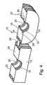
- the recess 7 is penetrated in the assembled state of the cable 4, wherein between the outer circumference of the cable 4 and the two inner edges 8, 9 of the recess 7 a split sealing element 10 is arranged, that is shown enlarged in Fig. 4.
- the split sealing element 10 consists of two sealing segments 12, 13, which are integrally connected to each other here via a film hinge 14 and complement each other in the assembled state to the full 360 ° sealing element, which encloses the cable 4 all around.
- the cable 4 may, as shown here, be a round cable or else a flat cable or have a different geometry (for example oval), the concept of the sealing segments being respectively maintained accordingly.
- the sealing segments 12, 13 are here each formed as a ring halves which extend over an angle of 180 ° and which together form a 360 ° ring around the cable.
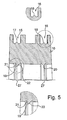
- the sealing segments 12, 13 are each provided with radially extending grooves 15, 16, which are adapted to each form fit one of the inner edges 8, 9 of the housing record. At the bottom of the grooves 15, 16 each have a circumferential bead 17, 18 is formed, which serves to increase the sealing effect.
- annular beads 19, 20 are further formed, which are each designed to realize a defined line-like contact on the inner circumference of the sealing segments 12, 13 on the cable 4, to ensure a sufficient sealing effect in this area.
- the annular beads 19, 20 have in the cross section of Fig. 5 an approximate triangular shape, wherein the two side surfaces 21, 22 are inclined differently strong to the wall plane, which in turn improves the sealing effect.
- sealing segment surfaces 23, 24, 25, 26, with which the sealing segments 12, 13 in the assembled state to each other, are substantially planar or formed form a (each at each ring segment preferably common, radial) plane E, so that the sealing segment 12, 13 complement each other in the assembled state to the complete ring element.
- the sealing-segment surfaces 23-26 since there is an effect of occasionally forming a gap between the sealing-segment surfaces 23-26 abutting each other, it is provided that at least one or more-especially two or even all-of the sealing-segment surfaces 23-26 do not project toward the inner periphery but have projections 27, 28 which project something (in particular more than 0.5 mm, preferably about 0.8 mm) over the plane E (in the direction of the other sealing segment) of the otherwise flat sealing segment surfaces 23 to 26.
- the height of the projections 27 preferably increases radially from outside to inside.
- the volume of the projections 27 is preferably less than 0.01%, in particular less than 0.005%, of the total volume of the sealing segments 12, 13.
- the projections 27 are formed substantially in the region of the annular beads 19, 20 and do not extend over the entire - with respect to the extension of the cable 4 - axial region of the inner circumference of the sealing segments 12, 13. It is advantageous , when the projections 27 attach axially each side of the annular beads 19, 20 and when their height increases axially in the region of the annular beads 19, 20 to a maximum, as this contributes to a particularly optimal sealing effect and prevention of the splitting effect.
- the cable 4 is first placed in one of the sealing segments 12 (FIG. 1) and then the second sealing segment 13 unfolded (FIG. 2). Then, the thus preassembled arrangement is placed in the recess 7 of the wall 5.
- the housing part 2 is closed with the cover part 3, wherein the sealing segments 12, 13 are pressed against each other.
- the sealing segments 12, 13 are pressed against each other.
- the recess 7 expands towards the edge (e.g., conical towards the lid).
- the sealing body of the seal or the sealing element 10 is rounded at the bottom and laterally preferably completely or substantially parallel, i. he does not or does not completely follow the widening contour. Therefore, if now the cover part 3 is mounted after mounting the seal 10, the effect arises that the rubber lips or projections are also pressed from the side of the cable or conductor surface, which has a complementary beneficial effect.
- the material projection of the projections 27, 28 is dimensioned such that they can be readily compressed so far, so that the direct superimposition of the sealing segment surfaces 23 - 26 is not hindered in the assembled state.
- This is advantageous in prefabrication on the conductor, since the seal is held on the conductor in this way.
- each two of the sealing segment surfaces 23, 25 provided with protruding projections in the manner of nubs 30 and the corresponding sealing segment surfaces 24, 26 with these nubs 28 in the folded state of the seal receiving holes 29th
- sealing segment surfaces 23 - 26 - preferably all - in addition to the inner circumference back with the projections 27, 28 are provided, wherein in each case in the axial direction on the inner circumference in the central region, a first projection 27 a, 28 a Extension of a central inner circumferential annular bead 31 is provided with a preferably flattened, for example, parabolic shape.
- a central inner circumferential annular bead 31 is provided with a preferably flattened, for example, parabolic shape.
- At the middle annular bead 31 are laterally wave-like smaller annular beads 32 at. Laterally close to this finally higher edge annular beads 33 to the two inner and outer end faces back to the turn in the region of the sealing segment surfaces 23 to 26 in projections 27b, 28b, so that a particularly advantageous combined sealing effect, especially to the End faces out, yields.
- the projections 27, 28 again only or substantially only in the region of the annular beads 31 and 33 are formed so that they do not extend axially over the entire region of the inner circumference of the sealing segments 12, 13.
Landscapes
- Engineering & Computer Science (AREA)
- Architecture (AREA)
- Civil Engineering (AREA)
- Structural Engineering (AREA)
- Installation Of Indoor Wiring (AREA)
- Cable Accessories (AREA)
- Insulating Bodies (AREA)
- Insertion, Bundling And Securing Of Wires For Electric Apparatuses (AREA)
Abstract
Description
- Die Erfindung betrifft eine Dichtung für eine Gehäusedurchführung für ein Kabel, die als geteiltes Dichtelement ausgebildet ist, nach dem Oberbegriff des Anspruchs 1.
- Geteilte Dichtungen für Gehäusedurchführungen sind aus dem Stand der Technik an sich bekannt.
- An den bekannten geteilten Dichtungen für Wanddurchführungen ist nachteilig, dass gelegentlich am Innenumfang der ringartigen Dichtungen im Anlagebereich zum Kabel hin Undichtigkeiten auftreten.
- Die Lösung dieses Problems ist die Aufgabe der Erfindung.
- Die Erfindung löst diese Aufgabe durch den Gegenstand des Anspruchs 1.
- Durch die Vorsprünge wird einer Spaltbildung am Innenumfang, welche die Ursache für einen wesentlichen Teil der Dichtungsprobleme am Innenumfang der geteilten Dichtung wird, auf einfache Weise entgegengewirkt, da die Vorsprünge den Bereich, in dem sich ein Spalt zwischen den Dichtsegmenten bilden könnte, überbrücken.
- Besonders vorteilhaft ist es, wenn die Vorsprünge nur oder im Wesentlichen nur im Bereich des wenigstens einen Ringwulstes ausgebildet sind, derart, dass sie sich axial und/oder auch radial nicht über den gesamten Bereich der Dichtsegmente erstrecken. Hierdurch wird besonders gezielt zum Innenumfang hin die Dichtwirkung optimiert.
- Vorteilhafte Ausgestaltungen der Erfindung sind den Unteransprüchen zu entnehmen.
- Nachfolgend wird die Erfindung unter Bezug auf die Zeichnung anhand von Ausführungsbeispielen näher erläutert. Es zeigt:
- Fig. 1 bis 3
- Elemente einer Wanddurchführung während mehrerer aufeinanderfolgender Montageschritte;
- Fig. 4
- eine perspektivische Ansicht der Dichtung der Wanddurchführung aus Fig. 1 bis 3;
- Fig. 5 und 6
- verschiedene Schnittansichten der Dichtung aus Fig. 3 und Detailvergrößerungen dieser Schnittansichten;
- Fig. 7
- eine Ansicht eines weiteren Ausführungsbeispiels einer erfindungsgemäßen Dichtung; und
- Fig. 8a-c
- verschiedene Ansichten einer weiteren Dichtung und ein Gehäuse.
- Fig. 1 zeigt ein Gehäuse 1 mit einem Grundteil 2 und einem (z.B. auf dieses aufschraubbaren) Deckelteil 3 zum Verschließen des Grundteils 2.
- Das Gehäuse 1 kann zur Aufnahme an sich beliebiger Bauelemente dienen, die Anschlusselemente zum Anschluss der Leiter eines Kabels 4 umfassen können.
- Eine Wand 5 des Gehäuses ist zur Realisierung einer Gehäusedurchführung 6 mit einer Öffnung versehen, die hier beispielhaft als Aussparung 7 im zum Deckelteil 3 weisenden Randbereich der Wand 5 ausgebildet ist.
- Die Wand 5 ist zumindest im Randbereich der Öffnung, hier der Aussparung 7, zweischichtig als eine Art Doppelrand mit zwei senkrecht zur Wandfläche zueinander beabstandeten Innenrändern 8, 9 ausgebildet. Im Deckelteil 3 kann ein entsprechender Doppelrand ausgebildet sein bzw. an diesem angeordnet sein (hier nicht zu erkennen).
- Die Aussparung 7 wird im montierten Zustand von dem Kabel 4 durchsetzt, wobei zwischen dem Außenumfang des Kabels 4 und den beiden Innenrändern 8, 9 der Aussparung 7 ein geteiltes Dichtelement 10 angeordnet ist, dass vergrößert in Fig. 4 dargestellt ist.
- Das geteilte Dichtelement 10 besteht aus zwei Dichtsegmenten 12, 13, die hier über ein Filmscharnier 14 einstückig miteinander verbunden sind und die einander im montierten Zustand zum vollen 360°-Dichtelement ergänzen, der das Kabel 4 rundum einschließt. Das Kabel 4 kann wie hier dargestellt ein Rundkabel oder aber auch ein Flachkabel sein oder eine sonstige Geometrie aufweisen (z.B. oval), wobei das Konzept der Dichtsegmente jeweils entsprechend beibehalten würde.
- Die Dichtsegmente 12, 13 sind hier jeweils als Ringhälften ausgebildet, die sich über einen Winkel von 180° erstrecken und die zusammen um das Kabel herum einen 360°-Ring bilden.
- An ihrem Außenumfang - siehe Fig. 5 - sind die Dichtsegmente 12, 13 jeweils mit radial verlaufenden Nuten 15, 16 versehen, die dazu ausgelegt sind, jeweils formschlüssig einen der Innenränder 8, 9 des Gehäuses aufnehmen. Am Grund der Nuten 15, 16 ist jeweils ein umlaufender Wulst 17, 18 ausgebildet, der dazu dient, die Dichtwirkung zu erhöhen.
- Am Innenumfang der Dichtsegmente 12, 13 sind ferner zwei stegartige Ringwulste 19, 20 ausgebildet, die dazu ausgelegt sind, jeweils eine definierte linienartige Anlage am Innenumfang der Dichtsegmente 12, 13 am Kabel 4 zu realisieren, um auch in diesem Bereich eine genügende Dichtwirkung sicherzustellen. Die Ringwulste 19, 20 weisen im Querschnitt der Fig. 5 eine angenäherte Dreiecksform auf, wobei die beiden Seitenflächen 21, 22 unterschiedlich stark zur Wandebene geneigt sind, was wiederum die Dichtwirkung verbessert.
- Die Dichtsegmentflächen 23, 24, 25, 26, mit welchen die Dichtsegmente 12, 13 im montierten Zustand aneinander liegen, sind im Wesentlichen eben ausgebildet bzw. bilden eine (jeweils an jedem Ringssegment vorzugsweise gemeinsame, radiale) Ebene E, so dass sich die Dichtsegment 12, 13 im montierten Zustand an sich zum vollständigen Ringelement ergänzen.
- Da jedoch der Effekt auftritt, dass sich zum Innenumfang hin gelegentlich ein Spalt zwischen den aneinander zur Anlage kommende Dichtsegmentflächen 23 - 26 bildet, ist vorgesehen, dass wenigstens eine oder mehrere - insbesondere zwei oder sogar alle - der Dichtsegmentflächen 23 -26 zum Innenumfang hin nicht eben verlaufen sondern Vorsprünge 27, 28 aufweisen, die etwas (insbesondere mehr als 0,5 mm, vorzugsweise ca. 0,8 mm) über die Ebene E (in Richtung des anderen Dichtsegmentes) der ansonsten ebenen Dichtsegmentflächen 23 bis 26 vorstehen. Dabei steigt die Höhe der Vorsprünge 27 vorzugsweise radial von außen nach innen an.
- Vorzugsweise beträgt das Volumen der Vorsprünge 27 weniger als 0,01%, insbesondere weniger als 0,005% des Gesamtvolumens der Dichtsegmente 12, 13.
- Nach Fig. 4 bis 6 sind die Vorsprünge 27 im Wesentlichen im Bereich der Ringwülste 19, 20 ausgebildet und erstrecken sich nicht über den gesamten - in Hinsicht auf die Erstreckung des Kabels 4 - axialen Bereich des Innenumfangs der Dichtsegmente 12, 13. Es ist vorteilhaft, wenn die Vorsprünge 27 axial jeweils seitlich der Ringwulste 19, 20 ansetzen und wenn deren Höhe axial im Bereich der Ringwulste 19, 20 zu einem Maximum ansteigt, da dies zu einer besonders optimalen Dichtwirkung und Verhinderung der Spaltwirkung beiträgt.
- Bei der Montage wird zunächst das Kabel 4 in eines der Dichtsegmente 12 gelegt (Fig. 1) und dann das zweite Dichtsegment 13 aufgeklappt (Fig. 2). Sodann wird die derart vormontierte Anordnung in die Aussparung 7 der Wand 5 gesetzt.
- Jetzt wird das Gehäuseteil 2 mit dem Deckelteil 3 verschlossen, wobei die Dichtsegmente 12, 13 aufeinander gedrückt werden. Insbesondere zum Kabel hin werden durch den leichten realisierten Materialüberstand bzw. die jetzt komprimierten Vorsprünge 27 Spaltbildungen, welche die Dichtwirkung beeinträchtigen könnten, auf einfache Weise vermieden.
- Die Aussparung 7 weitet sich zum Rand hin auf (z.B. konisch zum Deckel hin). Der Dichtkörper der Dichtung bzw. des Dichtelementes 10 ist unten abgerundet ausgebildet und seitlich vorzugsweise ganz oder im Wesentlichen parallel, d.h. er folgt der sich aufweitenden Kontur nicht oder nicht ganz. Wird daher nach dem Montieren der Dichtung 10 jetzt das Deckelteil 3 aufgesetzt, entsteht der Effekt, dass die Gummilippen bzw. Vorsprünge auch von der Seite auf die Kabel- bzw. Leiteroberfläche gepresst werden, was sich ergänzend vorteilhaft auswirkt.
- Der Materialüberstand der Vorsprünge 27, 28 ist derart bemessen, dass diese sich ohne weiteres so weit komprimieren lassen, so dass das direkte Aufeinanderliegen der Dichtsegmentflächen 23 - 26 im montierten Zustand nicht behindert wird.
- Bei dem Ausführungsbeispiel der Fig. 7 sind jeweils zwei der Dichtsegmentflächen 23, 25 mit vorkragenden Vorsprüngen, insbesondere nach Art von Noppen 30, versehen und die korrespondierenden Dichtsegmentflächen 24, 26 mit diese Noppen 28 im zusammengeklappten Zustand der Dichtung aufnehmenden Löchern 29, so dass der Sitz und Zusammenhalt der Dichtung im zusammengeklappten Zustand optimiert wird. Dies ist bei der Vorkonfektionierung am Leiter vorteilhaft, da die Dichtung derart am Leiter gehalten ist. Darüber hinaus ergibt sich eine Zentrierung und eine Erleichterung der Montage.
- Auch bei dem Ausführungsbeispiel der Fig. 8 sind jeweils zwei der Dichtsegmentflächen 23, 25 mit vorkragenden Vorsprüngen nach Art von Noppen 30 versehen und die korrespondierenden Dichtsegmentflächen 24, 26 mit diese Noppen 28 im zusammengeklappten Zustand der Dichtung aufnehmenden Löchern 29.
- Zudem sind die Dichtsegmentflächen 23 -26 - vorzugsweise alle - zudem zum Innenumfang hin wiederum mit den Vorsprüngen 27, 28 versehen, wobei jeweils in axialer Richtung am Innenumfang im mittleren Bereich ein erster Vorsprung 27a, 28a als Fortsatz einer mittleren Innenumfangs-Ringwulst 31 mit vorzugsweise abgeflachter, beispielsweise parabelförmiger Form vorgesehen ist. An die mittlere Ringwulst 31 schließen sich seitlich wellenartig kleinere Ringwulste 32 an. Seitlich schließen sich an diese schließlich höhere Rand-Ringwulste 33 zu den beiden inneren und äußeren Stirnseiten hin an, die im Bereich der Dichtsegmentflächen 23 bis 26 wiederum in Vorsprünge 27b, 28b übergehen, so dass sich eine besonders vorteilhafte kombinierte Dichtwirkung, gerade auch zu den Stirnflächen hin, ergibt.
- Auch hier sind die Vorsprünge 27, 28 wiederum nur oder im Wesentlichen nur im Bereich der Ringwulste 31 und 33 ausgebildet, so dass sie sich axial nicht über den gesamten Bereich des Innenumfangs der Dichtsegmente 12, 13 erstrecken.
-
- Gehäuse
- 1
- Grundteil
- 2
- Deckelteil
- 3
- Kabel
- 4
- Wand
- 5
- Gehäusedurchführung
- 6
- Aussparung
- 7
- Ränder
- 8, 9
- Dichtelement
- 10
- Dichtsegmente
- 12, 13
- Nuten
- 15, 16
- Wulst
- 17, 18, 19, 20
- Seitenflächen
- 21, 22
- Dichtsegmentflächen
- 23, 24, 25, 26
- Vorsprünge
- 27, 28
- Löcher
- 29
- Noppen
- 30
- Ringwulste
- 31 bis 33
- Ebene
- E
Claims (17)
- Dichtung für eine Gehäusedurchführung für ein Kabel (4), die als geteiltes Dichtelement (10) ausgebildet ist, das wenigstens zwei Dichtsegmente (12, 13) mit Dichtsegmentflächen (23, 24, 25, 26) aufweist, an denen welchen die Dichtsegmente (12, 13) im montierten Zustand aneinander liegen, welche jeweils zumindest im wesentlichen eine ebene Fläche (Ebene E) aufweisen, dadurch gekennzeichnet, dass wenigstens eine oder mehrere - insbesondere alle - der Dichtsegmentflächen (23 -26) wenigstens einen einen Materialüberstand bildenden Vorsprung oder mehrere wenigstens einen Materialüberstand bildende Vorsprünge (27, 28) aufweisen, die im unmontierten Zustand etwas über die ansonsten ebene Fläche (Ebene E) vorstehen.
- Dichtung nach Anspruch 1, dadurch gekennzeichnet, dass die Vorsprünge (27, 28) mehr als 0,5 mm, vorzugsweise ca. 0,8 mm, über die ebene Fläche (Ebene E) vorstehen.
- Dichtung nach Anspruch 1 oder 2, dadurch gekennzeichnet, dass lediglich die Dichtsegmentflächen (23 - 26) von einem der beiden Ringssegmente (12) mit den Vorsprüngen (27, 28) versehen sind.
- Dichtung nach einem der vorstehenden Ansprüche, dadurch gekennzeichnet, dass die Vorsprünge (27, 28) nur oder im wesentlichen nur im Bereich des wenigstens einen Ringwulstes (19, 20) ausgebildet sind, derart, dass sie sich axial nicht über den gesamten Bereich des Innenumfangs der Dichtsegmente (12, 13) erstrecken.
- Dichtung nach einem der vorstehenden Ansprüche, dadurch gekennzeichnet, dass die Vorsprünge (27, 28) nur oder im wesentlichen nur im Bereich des wenigstens einen Ringwulstes (19, 20) ausgebildet sind, derart, dass sie sich radial nicht über den gesamten Bereich der Dichtsegmente (12, 13) erstrecken.
- Dichtung nach einem der vorstehenden Ansprüche, dadurch gekennzeichnet, dass sämtliche der Dichtsegmentflächen (23 - 26) der beiden Ringssegmente (12, 13) mit den Vorsprüngen (27, 28) versehen sind.
- Dichtung nach einem der vorstehenden Ansprüche, dadurch gekennzeichnet, dass das Volumen der Vorsprünge (27, 28) weniger als 0,01%, insbesondere weniger als 0,005%, des Gesamtvolumens der Dichtsegmente (12, 13) beträgt.
- Dichtung nach einem der vorstehenden Ansprüche, dadurch gekennzeichnet, dass die Höhe der Vorsprünge (27, 28) radial von außen nach innen zum Kabel (4) hin ansteigt.
- Dichtung nach einem der vorstehenden Ansprüche, dadurch gekennzeichnet, dass am Innenumfang der Dichtsegmente (12, 13) wenigstens ein oder mehrere Ringwulst(e) (19, 20) ausgebildet ist/sind, der/die dazu ausgelegt ist/sind, jeweils eine definierte linienartige Anlage der Dichtsegmente (12, 13) am Kabel (4) zu realisieren.
- Dichtung nach einem der vorstehenden Ansprüche, dadurch gekennzeichnet, dass die Ringwulste im Querschnitt eine angenäherte Dreiecksform aufweisen, wobei die beiden Seitenflächen (21, 22) unterschiedlich stark geneigt sind.
- Dichtung nach einem der vorstehenden Ansprüche, dadurch gekennzeichnet, dass die Vorsprünge (27, 28) axial jeweils seitlich der Ringwulste (19, 20) ansetzen und zu einer maximalen Höhe im Bereich der Ringwulste (19, 20) ansteigen.
- Dichtung nach einem der vorstehenden Ansprüche, dadurch gekennzeichnet, dass die Dichtsegmente (12, 13) an ihrem Außenumfang jeweils mit radial verlaufenden Nuten (15, 16) versehen sind, die dazu ausgelegt sind, jeweils formschlüssig einen der Ränder (8, 9) eines Doppelrandes der Gehäusewandung aufnehmen.
- Dichtung nach einem der vorstehenden Ansprüche, dadurch gekennzeichnet, dass die Dichtsegmente (12, 13) als Ringhälften ausgebildet sind, die sich über einen Winkel von 180° erstrecken.
- Dichtung nach einem der vorstehenden Ansprüche, dadurch gekennzeichnet, dass die Dichtsegmente (12, 13) über ein Filmscharnier (14) einstückig miteinander verbunden sind.
- Dichtung nach einem der vorstehenden Ansprüche mit Gehäuse, dadurch gekennzeichnet, dass sich die Aussparung (7) zum Deckel hin aufweitet.
- Dichtung nach einem der vorstehenden Ansprüche mit Gehäuse, dadurch gekennzeichnet, dass sich die Aussparung (7) zum Deckel hin konisch aufweitet.
- Dichtung nach einem der vorstehenden Ansprüche mit Gehäuse, dadurch gekennzeichnet, dass eine oder vorzugsweise zwei der Dichtsegmentflächen (23, 25) mit vorkragenden Vorsprüngen, insbesondere nach Art von Noppen (28), versehen ist/sind und die korrespondierenden Dichtsegmentflächen (24, 26) mit einem oder zwei diese Noppen (30) im zusammengeklappten Zustand der Dichtung aufnehmenden Loch/Löchern (29).
Applications Claiming Priority (2)
| Application Number | Priority Date | Filing Date | Title |
|---|---|---|---|
| DE202006004314 | 2006-03-18 | ||
| DE202006017659U DE202006017659U1 (de) | 2006-03-18 | 2006-11-21 | Dichtung für eine Gehäusedurchführung für ein Kabel |
Publications (3)
| Publication Number | Publication Date |
|---|---|
| EP1843441A2 true EP1843441A2 (de) | 2007-10-10 |
| EP1843441A3 EP1843441A3 (de) | 2011-03-23 |
| EP1843441B1 EP1843441B1 (de) | 2012-08-01 |
Family
ID=38329670
Family Applications (1)
| Application Number | Title | Priority Date | Filing Date |
|---|---|---|---|
| EP07100895A Not-in-force EP1843441B1 (de) | 2006-03-18 | 2007-01-22 | Dichtung für eine Gehäusedurchführung für ein Kabel |
Country Status (3)
| Country | Link |
|---|---|
| US (1) | US7781684B2 (de) |
| EP (1) | EP1843441B1 (de) |
| DE (1) | DE202006017659U1 (de) |
Cited By (6)
| Publication number | Priority date | Publication date | Assignee | Title |
|---|---|---|---|---|
| DE202008015307U1 (de) | 2008-11-19 | 2010-04-08 | Weidmüller Interface GmbH & Co. KG | Anschluss-System zur Realisierung von Abzweigungen an durchgehenden Leitern |
| DE202008015310U1 (de) | 2008-11-19 | 2010-04-08 | Weidmüller Interface GmbH & Co. KG | Baugruppe aus zwei oder mehr Anschlussvorrichtungen zur Realisierung von Abzweigungen an durchgehenden Leitern |
| DE202010008934U1 (de) | 2010-11-02 | 2012-02-03 | Weidmüller Interface GmbH & Co. KG | Anschluss-System mit Bodenanschluss |
| DE102016102671A1 (de) * | 2016-02-16 | 2017-08-17 | Reichle & De-Massari Ag | Kontaktgehäusevorrichtung, Baukastensystem zur Herstellung einer Kontaktgehäusevorrichtung und Verfahren zur Herstellung einer Kontaktgehäusevorrichtung unter Verwendung eines Baukastensystems |
| EP3726101A4 (de) * | 2017-12-11 | 2021-01-27 | Qingdao Haier Co., Ltd. | Kühlschrank |
| WO2024022715A1 (de) * | 2022-07-28 | 2024-02-01 | Lisa Dräxlmaier GmbH | Abdichtbares gehäuse für eine flachleiterschienenanordnung |
Families Citing this family (41)
| Publication number | Priority date | Publication date | Assignee | Title |
|---|---|---|---|---|
| ES2394649T3 (es) | 2006-03-20 | 2013-02-04 | Beele Engineering B.V. | Sistema para sellar dinámicamente un manguito de canalización a través del cual se extiende un tubo o cable |
| JP5056619B2 (ja) * | 2008-06-30 | 2012-10-24 | 株式会社明電舎 | 電気機器のケーブル取付け構造 |
| FR2943470A1 (fr) * | 2009-03-19 | 2010-09-24 | Peugeot Citroen Automobiles Sa | Dispositif de passage de cable(s) electrique(s) pour une decoupe de feuillure |
| GB2469655B (en) * | 2009-04-22 | 2014-02-12 | Hager Engineering Ltd | Electrical enclosure apparatus, kit of parts and method |
| ES1071144Y (es) * | 2009-09-23 | 2010-04-15 | Beistegui Hermanos S L | Guia pasa-cables para bicicletas |
| ES2392791T3 (es) * | 2010-05-25 | 2012-12-13 | Beele Engineering B.V. | Un conjunto y un procedimiento para proporcionar un sistema de sellado en una abertura |
| US20120048616A1 (en) * | 2010-08-25 | 2012-03-01 | Ideal Industries, Inc. | Grommet assembly |
| USD715744S1 (en) | 2011-03-11 | 2014-10-21 | Roxtec Ab | Cable and pipe penetration seal |
| CN103124485B (zh) * | 2011-11-21 | 2015-11-25 | 神讯电脑(昆山)有限公司 | 线材防液结构及其电子装置 |
| JP5954782B2 (ja) * | 2012-08-10 | 2016-07-20 | 矢崎総業株式会社 | 電気接続箱 |
| ES2626753T3 (es) | 2012-08-30 | 2017-07-25 | Beele Engineering B.V. | Sistema de estanqueidad para un espacio anular |
| DE202012104999U1 (de) * | 2012-12-20 | 2014-04-01 | Weidmüller Interface GmbH & Co. KG | Adapteranordnung |
| NL2010304C2 (en) | 2013-02-14 | 2014-08-18 | Beele Eng Bv | System for sealingly holding cables which extend through an opening. |
| US9312670B1 (en) | 2013-03-09 | 2016-04-12 | Jeffrey Baldwin | Sealed cable conduit electrical box |
| US9169966B2 (en) * | 2013-03-14 | 2015-10-27 | Ford Global Technologies, Llc | Compression limiting clip for a bracket assembly |
| US20150138785A1 (en) * | 2013-11-15 | 2015-05-21 | Osram Sylvania Inc. | Enclosure with grommetless strain relief |
| DK3105626T3 (da) * | 2014-02-14 | 2021-01-11 | Prysmian Spa | Portforseglingsindretning og samling for en optisk kabelafslutningsboks |
| US10100948B2 (en) * | 2014-03-24 | 2018-10-16 | Claremont Products, LLC | Faucet insulation apparatus |
| US9450327B1 (en) | 2015-03-13 | 2016-09-20 | Technologies Holdings Corp. | Connector plug with flexible ridges and having a hook with a beveled surface |
| CN104875955B (zh) * | 2015-06-15 | 2016-11-30 | 浙江天衣机械有限公司 | 钢管支撑架以及钢管支撑装置 |
| SE539904C2 (en) * | 2015-12-18 | 2018-01-09 | Roxtec Ab | Module of a seal or transition |
| US10247424B2 (en) * | 2016-09-09 | 2019-04-02 | Haier Us Appliance Solutions, Inc. | Oven appliance with a door hinge |
| EP3361586B1 (de) | 2017-02-10 | 2020-12-02 | Robert Bosch GmbH | Tülle zum abdichten eines kabels in einer kabeldurchführung und tüllenanordnung |
| ES2959795T3 (es) * | 2017-05-23 | 2024-02-28 | Prysmian Spa | Un dispositivo de sellado de puerto para una caja de terminación de cable óptico |
| DE202017104619U1 (de) * | 2017-08-02 | 2018-12-13 | Doyma Gmbh & Co | Dichtungsmodul und Dichtungsanordnung mit einem oder mehreren Dichtungsmodulen |
| JP6446525B1 (ja) * | 2017-12-01 | 2018-12-26 | 品川商工株式会社 | 配線用グロメット |
| DE102018101790A1 (de) * | 2018-01-26 | 2019-08-01 | Harting Electric Gmbh & Co. Kg | Dichteinsatz |
| DE102018104915A1 (de) * | 2018-03-05 | 2019-09-05 | Te Connectivity Germany Gmbh | Dichtungseinrichtung für eine Leitung sowie elektrischer Verbinder |
| EP4220262A1 (de) | 2018-05-09 | 2023-08-02 | AFL Telecommunications LLC | Stumpfverschlüsse und sockel dafür |
| DE102018113247A1 (de) * | 2018-06-04 | 2019-12-05 | Reichle & De-Massari Ag | Dichtvorrichtung |
| GB2575108A (en) * | 2018-06-29 | 2020-01-01 | Airbus Operations Ltd | Aircraft cable routing system and method of installation thereof |
| CN108695799B (zh) * | 2018-08-13 | 2023-08-25 | 珠海格力电器股份有限公司 | 过线结构、电器盒及空调器 |
| WO2020248199A1 (zh) * | 2019-06-13 | 2020-12-17 | 华为技术有限公司 | 一种光缆固定结构、光缆连接装置 |
| TWI735985B (zh) * | 2019-10-24 | 2021-08-11 | 和碩聯合科技股份有限公司 | 密封裝置 |
| CN113056127B (zh) * | 2019-12-27 | 2024-12-27 | 鸿富锦精密电子(郑州)有限公司 | 壳体组件及具有该壳体组件的电子装置 |
| DE102020104994A1 (de) * | 2020-02-26 | 2021-08-26 | Harting Electric Gmbh & Co. Kg | Kabeleinlassvorrichtung für einen Schaltschrank sowie Anordnung und Verfahren zum Betrieb derselben |
| US10996414B1 (en) | 2020-03-23 | 2021-05-04 | Afl Telecommunications Llc | Butt closures and bases therefor |
| US12078846B2 (en) | 2020-11-30 | 2024-09-03 | Afl Telecommunications Llc | Butt closures and bases therefor |
| US12241632B2 (en) * | 2022-02-01 | 2025-03-04 | Haier Us Appliance Solutions, Inc. | Concave recess for flush mount of a built-in appliance |
| WO2023168052A1 (en) * | 2022-03-03 | 2023-09-07 | Ppc Broadband, Inc. | Cable enclosure assembly having receiving area configured to alternatively receive cable retainer and cable adapter to allow plurality of configurations |
| US12413183B2 (en) * | 2022-11-15 | 2025-09-09 | GAF Energy LLC | Electrical cable passthrough for photovoltaic systems |
Family Cites Families (18)
| Publication number | Priority date | Publication date | Assignee | Title |
|---|---|---|---|---|
| US3161906A (en) * | 1961-11-07 | 1964-12-22 | Sidney D Yarm | Split bushing |
| US3836269A (en) * | 1973-09-26 | 1974-09-17 | Illinois Tool Works | Cable sealing grommet |
| US4517408A (en) * | 1983-07-27 | 1985-05-14 | Amp Incorporated | Self-centering cable fastener |
| NL8403650A (nl) * | 1984-11-30 | 1986-06-16 | Johannes Alfred Beele | Doorvoerinrichting. |
| GB2186440B (en) * | 1986-02-11 | 1990-03-14 | Hawke Cable Glands Ltd | Improved transit for cables and pipes |
| FR2723162B1 (fr) * | 1994-07-29 | 1996-10-04 | Connecteurs Albert Bonneau Cab | Joint annulaire d'etancheite |
| DE19701511C2 (de) | 1996-01-18 | 2000-10-26 | Draexlmaier Lisa Gmbh | Tülle zur Durchführung von elektrischen Leitungen durch Wandungen, insbesondere in Kraftfahrzeugen |
| FR2762455B1 (fr) * | 1997-04-16 | 1999-06-25 | Sofanou Sa | Piece de raccordement etanche d'un tube a l'orifice d'une paroi |
| SE515160C2 (sv) * | 1999-10-08 | 2001-06-18 | Roxtec Ab | Kabelgenomföring |
| AT410734B (de) | 2000-03-14 | 2003-07-25 | Bst Brandschutztechnik Doepfl | Dichtungselement für eine vorrichtung zur brandgesicherten durchführung von leitungen durch in wänden befindliche öffnungen hindurch |
| NL1016703C2 (nl) * | 2000-11-24 | 2002-05-27 | Beele Eng Bv | Doorvoerinrichting. |
| US6623303B2 (en) | 2001-08-31 | 2003-09-23 | Hewlett-Packard Development Company, L.P. | Cable shield termination system using clamps and ferrules |
| JP3940308B2 (ja) * | 2002-03-27 | 2007-07-04 | 矢崎総業株式会社 | ハーネス固定具 |
| DE10349440B4 (de) | 2003-10-23 | 2008-05-08 | Wieland Electric Gmbh | Dichte Wanddurchführung mit Zugentlastung |
| SE526243C2 (sv) * | 2003-12-12 | 2005-08-02 | Roxtec Ab | Genomföringsanordning för kablar eller rör |
| US7355130B2 (en) * | 2004-04-09 | 2008-04-08 | Siemens Information And Communication Networks, Inc. | Cable sealing device |
| DE102004040661B4 (de) | 2004-08-20 | 2006-06-08 | Gk-System Gmbh | Vorrichtung zur Abdichtung von Leitungsdurchführungen |
| US7049515B1 (en) * | 2005-05-20 | 2006-05-23 | Emerson Electric Co. | Grommets for sealing a hole in an electrical device housing through which electrical connectors exit |
-
2006
- 2006-11-21 DE DE202006017659U patent/DE202006017659U1/de not_active Expired - Lifetime
-
2007
- 2007-01-22 EP EP07100895A patent/EP1843441B1/de not_active Not-in-force
- 2007-02-27 US US11/711,209 patent/US7781684B2/en active Active
Cited By (9)
| Publication number | Priority date | Publication date | Assignee | Title |
|---|---|---|---|---|
| DE202008015307U1 (de) | 2008-11-19 | 2010-04-08 | Weidmüller Interface GmbH & Co. KG | Anschluss-System zur Realisierung von Abzweigungen an durchgehenden Leitern |
| DE202008015310U1 (de) | 2008-11-19 | 2010-04-08 | Weidmüller Interface GmbH & Co. KG | Baugruppe aus zwei oder mehr Anschlussvorrichtungen zur Realisierung von Abzweigungen an durchgehenden Leitern |
| WO2010057750A3 (de) * | 2008-11-19 | 2011-05-12 | Weidmüller Interface GmbH & Co. KG | Baugruppe aus zwei oder mehr anschlussvorrichtungen zur realisierung von abzweigungen an durchgehenden leitern |
| US8298019B2 (en) | 2008-11-19 | 2012-10-30 | Weidmueller Interface Gmbh & Co. Kg | Connecting system for implementing branches on continuous conductors |
| DE202010008934U1 (de) | 2010-11-02 | 2012-02-03 | Weidmüller Interface GmbH & Co. KG | Anschluss-System mit Bodenanschluss |
| DE102016102671A1 (de) * | 2016-02-16 | 2017-08-17 | Reichle & De-Massari Ag | Kontaktgehäusevorrichtung, Baukastensystem zur Herstellung einer Kontaktgehäusevorrichtung und Verfahren zur Herstellung einer Kontaktgehäusevorrichtung unter Verwendung eines Baukastensystems |
| EP3417520A1 (de) * | 2016-02-16 | 2018-12-26 | Reichle & De-Massari AG | Kontaktgehäusevorrichtung, baukastensystem zur herstellung einer kontaktgehäusevorrichtung und verfahren zur herstellung einer kontaktgehäusevorrichtung unter verwendung eines baukastensystems |
| EP3726101A4 (de) * | 2017-12-11 | 2021-01-27 | Qingdao Haier Co., Ltd. | Kühlschrank |
| WO2024022715A1 (de) * | 2022-07-28 | 2024-02-01 | Lisa Dräxlmaier GmbH | Abdichtbares gehäuse für eine flachleiterschienenanordnung |
Also Published As
| Publication number | Publication date |
|---|---|
| EP1843441A3 (de) | 2011-03-23 |
| US7781684B2 (en) | 2010-08-24 |
| EP1843441B1 (de) | 2012-08-01 |
| US20070216110A1 (en) | 2007-09-20 |
| DE202006017659U1 (de) | 2007-08-02 |
Similar Documents
| Publication | Publication Date | Title |
|---|---|---|
| EP1843441B1 (de) | Dichtung für eine Gehäusedurchführung für ein Kabel | |
| DE69528279T2 (de) | Druckmittelbetätigte dichtung für radiale luftfilter | |
| EP2941798B1 (de) | Umweltdichtes steckverbindergehäuse | |
| EP1760854B1 (de) | Kabeldurchführung | |
| DE19922471A1 (de) | Kabeldurchführung mit einem elastischen Flansch zur Befestigung an einer Verkleidung | |
| DE102004043978B4 (de) | Dichtung | |
| DE102018217222B4 (de) | Durchführungshülse | |
| WO2018210892A1 (de) | Kabeldurchführung | |
| DE4207602A1 (de) | Kugelzapfengelenk | |
| DE2816645A1 (de) | Anordnung zur drehbaren verbindung eines saugschlauches mit einem kupplungsstueck bei einem staubsauger | |
| EP0317903A1 (de) | Dichtring | |
| BE1030586B1 (de) | Anschlussvorrichtung | |
| DE102012103550A1 (de) | Steckdose | |
| DE19941820C1 (de) | Sanitärarmatur | |
| DE102021112600A1 (de) | Tülle | |
| DE29710298U1 (de) | Antrieb für Verstelleinrichtung, insbesondere an Sitz- und Liegemöbeln | |
| DE9209268U1 (de) | Leuchte für Fahrzeuge | |
| DE202016102116U1 (de) | Befestigungsanordnung für die Befestigung einer Flanschplatte an einem Schaltschrankgehäuse und ein entsprechendes Schaltschrankgehäuse | |
| DE102018211262B4 (de) | Ladeklappensystem eines elektrisch angetriebenen Fahrzeugs | |
| DE60218954T2 (de) | Trägerstruktur für eine elektrische Tauchmotor | |
| DE2805509A1 (de) | Rohrverbinder | |
| EP1319608B1 (de) | Behälter, insbesondere Paletteninnenbehälter | |
| DE102014101725B4 (de) | Kraftstofffiltervorrichtung | |
| EP3961160B1 (de) | Sensorgehäuse | |
| WO1992013233A1 (de) | Verbindungseinrichtung zur drehbaren verbindung einer leuchtenwanne mit einem leuchtengehäuse |
Legal Events
| Date | Code | Title | Description |
|---|---|---|---|
| PUAI | Public reference made under article 153(3) epc to a published international application that has entered the european phase |
Free format text: ORIGINAL CODE: 0009012 |
|
| AK | Designated contracting states |
Kind code of ref document: A2 Designated state(s): AT BE BG CH CY CZ DE DK EE ES FI FR GB GR HU IE IS IT LI LT LU LV MC NL PL PT RO SE SI SK TR |
|
| AX | Request for extension of the european patent |
Extension state: AL BA HR MK YU |
|
| PUAL | Search report despatched |
Free format text: ORIGINAL CODE: 0009013 |
|
| AK | Designated contracting states |
Kind code of ref document: A3 Designated state(s): AT BE BG CH CY CZ DE DK EE ES FI FR GB GR HU IE IS IT LI LT LU LV MC NL PL PT RO SE SI SK TR |
|
| AX | Request for extension of the european patent |
Extension state: AL BA HR MK RS |
|
| 17P | Request for examination filed |
Effective date: 20110916 |
|
| AKX | Designation fees paid |
Designated state(s): AT BE BG CH CY CZ DE DK EE ES FI FR GB GR HU IE IS IT LI LT LU LV MC NL PL PT RO SE SI SK TR |
|
| GRAP | Despatch of communication of intention to grant a patent |
Free format text: ORIGINAL CODE: EPIDOSNIGR1 |
|
| GRAS | Grant fee paid |
Free format text: ORIGINAL CODE: EPIDOSNIGR3 |
|
| GRAA | (expected) grant |
Free format text: ORIGINAL CODE: 0009210 |
|
| AK | Designated contracting states |
Kind code of ref document: B1 Designated state(s): AT BE BG CH CY CZ DE DK EE ES FI FR GB GR HU IE IS IT LI LT LU LV MC NL PL PT RO SE SI SK TR |
|
| REG | Reference to a national code |
Ref country code: GB Ref legal event code: FG4D Free format text: NOT ENGLISH |
|
| REG | Reference to a national code |
Ref country code: AT Ref legal event code: REF Ref document number: 569089 Country of ref document: AT Kind code of ref document: T Effective date: 20120815 Ref country code: CH Ref legal event code: EP |
|
| REG | Reference to a national code |
Ref country code: IE Ref legal event code: FG4D Free format text: LANGUAGE OF EP DOCUMENT: GERMAN |
|
| REG | Reference to a national code |
Ref country code: DE Ref legal event code: R096 Ref document number: 502007010293 Country of ref document: DE Effective date: 20121011 |
|
| REG | Reference to a national code |
Ref country code: NL Ref legal event code: VDEP Effective date: 20120801 |
|
| REG | Reference to a national code |
Ref country code: LT Ref legal event code: MG4D Effective date: 20120801 |
|
| PG25 | Lapsed in a contracting state [announced via postgrant information from national office to epo] |
Ref country code: FI Free format text: LAPSE BECAUSE OF FAILURE TO SUBMIT A TRANSLATION OF THE DESCRIPTION OR TO PAY THE FEE WITHIN THE PRESCRIBED TIME-LIMIT Effective date: 20120801 Ref country code: LT Free format text: LAPSE BECAUSE OF FAILURE TO SUBMIT A TRANSLATION OF THE DESCRIPTION OR TO PAY THE FEE WITHIN THE PRESCRIBED TIME-LIMIT Effective date: 20120801 Ref country code: IS Free format text: LAPSE BECAUSE OF FAILURE TO SUBMIT A TRANSLATION OF THE DESCRIPTION OR TO PAY THE FEE WITHIN THE PRESCRIBED TIME-LIMIT Effective date: 20121201 Ref country code: CY Free format text: LAPSE BECAUSE OF FAILURE TO SUBMIT A TRANSLATION OF THE DESCRIPTION OR TO PAY THE FEE WITHIN THE PRESCRIBED TIME-LIMIT Effective date: 20120801 |
|
| PG25 | Lapsed in a contracting state [announced via postgrant information from national office to epo] |
Ref country code: LV Free format text: LAPSE BECAUSE OF FAILURE TO SUBMIT A TRANSLATION OF THE DESCRIPTION OR TO PAY THE FEE WITHIN THE PRESCRIBED TIME-LIMIT Effective date: 20120801 Ref country code: PL Free format text: LAPSE BECAUSE OF FAILURE TO SUBMIT A TRANSLATION OF THE DESCRIPTION OR TO PAY THE FEE WITHIN THE PRESCRIBED TIME-LIMIT Effective date: 20120801 Ref country code: PT Free format text: LAPSE BECAUSE OF FAILURE TO SUBMIT A TRANSLATION OF THE DESCRIPTION OR TO PAY THE FEE WITHIN THE PRESCRIBED TIME-LIMIT Effective date: 20121203 Ref country code: SI Free format text: LAPSE BECAUSE OF FAILURE TO SUBMIT A TRANSLATION OF THE DESCRIPTION OR TO PAY THE FEE WITHIN THE PRESCRIBED TIME-LIMIT Effective date: 20120801 Ref country code: SE Free format text: LAPSE BECAUSE OF FAILURE TO SUBMIT A TRANSLATION OF THE DESCRIPTION OR TO PAY THE FEE WITHIN THE PRESCRIBED TIME-LIMIT Effective date: 20120801 Ref country code: GR Free format text: LAPSE BECAUSE OF FAILURE TO SUBMIT A TRANSLATION OF THE DESCRIPTION OR TO PAY THE FEE WITHIN THE PRESCRIBED TIME-LIMIT Effective date: 20121102 |
|
| PG25 | Lapsed in a contracting state [announced via postgrant information from national office to epo] |
Ref country code: NL Free format text: LAPSE BECAUSE OF FAILURE TO SUBMIT A TRANSLATION OF THE DESCRIPTION OR TO PAY THE FEE WITHIN THE PRESCRIBED TIME-LIMIT Effective date: 20120801 |
|
| PG25 | Lapsed in a contracting state [announced via postgrant information from national office to epo] |
Ref country code: CZ Free format text: LAPSE BECAUSE OF FAILURE TO SUBMIT A TRANSLATION OF THE DESCRIPTION OR TO PAY THE FEE WITHIN THE PRESCRIBED TIME-LIMIT Effective date: 20120801 Ref country code: ES Free format text: LAPSE BECAUSE OF FAILURE TO SUBMIT A TRANSLATION OF THE DESCRIPTION OR TO PAY THE FEE WITHIN THE PRESCRIBED TIME-LIMIT Effective date: 20121112 Ref country code: EE Free format text: LAPSE BECAUSE OF FAILURE TO SUBMIT A TRANSLATION OF THE DESCRIPTION OR TO PAY THE FEE WITHIN THE PRESCRIBED TIME-LIMIT Effective date: 20120801 Ref country code: DK Free format text: LAPSE BECAUSE OF FAILURE TO SUBMIT A TRANSLATION OF THE DESCRIPTION OR TO PAY THE FEE WITHIN THE PRESCRIBED TIME-LIMIT Effective date: 20120801 Ref country code: RO Free format text: LAPSE BECAUSE OF FAILURE TO SUBMIT A TRANSLATION OF THE DESCRIPTION OR TO PAY THE FEE WITHIN THE PRESCRIBED TIME-LIMIT Effective date: 20120801 |
|
| PG25 | Lapsed in a contracting state [announced via postgrant information from national office to epo] |
Ref country code: SK Free format text: LAPSE BECAUSE OF FAILURE TO SUBMIT A TRANSLATION OF THE DESCRIPTION OR TO PAY THE FEE WITHIN THE PRESCRIBED TIME-LIMIT Effective date: 20120801 |
|
| PLBE | No opposition filed within time limit |
Free format text: ORIGINAL CODE: 0009261 |
|
| STAA | Information on the status of an ep patent application or granted ep patent |
Free format text: STATUS: NO OPPOSITION FILED WITHIN TIME LIMIT |
|
| 26N | No opposition filed |
Effective date: 20130503 |
|
| BERE | Be: lapsed |
Owner name: WEIDMULLER INTERFACE G.M.B.H. & CO. KG Effective date: 20130131 |
|
| PG25 | Lapsed in a contracting state [announced via postgrant information from national office to epo] |
Ref country code: BG Free format text: LAPSE BECAUSE OF FAILURE TO SUBMIT A TRANSLATION OF THE DESCRIPTION OR TO PAY THE FEE WITHIN THE PRESCRIBED TIME-LIMIT Effective date: 20121101 |
|
| REG | Reference to a national code |
Ref country code: DE Ref legal event code: R097 Ref document number: 502007010293 Country of ref document: DE Effective date: 20130503 |
|
| PG25 | Lapsed in a contracting state [announced via postgrant information from national office to epo] |
Ref country code: MC Free format text: LAPSE BECAUSE OF NON-PAYMENT OF DUE FEES Effective date: 20130131 |
|
| REG | Reference to a national code |
Ref country code: CH Ref legal event code: PL |
|
| GBPC | Gb: european patent ceased through non-payment of renewal fee |
Effective date: 20130122 |
|
| REG | Reference to a national code |
Ref country code: IE Ref legal event code: MM4A |
|
| PG25 | Lapsed in a contracting state [announced via postgrant information from national office to epo] |
Ref country code: BE Free format text: LAPSE BECAUSE OF NON-PAYMENT OF DUE FEES Effective date: 20130131 Ref country code: LI Free format text: LAPSE BECAUSE OF NON-PAYMENT OF DUE FEES Effective date: 20130131 Ref country code: CH Free format text: LAPSE BECAUSE OF NON-PAYMENT OF DUE FEES Effective date: 20130131 |
|
| PG25 | Lapsed in a contracting state [announced via postgrant information from national office to epo] |
Ref country code: GB Free format text: LAPSE BECAUSE OF NON-PAYMENT OF DUE FEES Effective date: 20130122 |
|
| PG25 | Lapsed in a contracting state [announced via postgrant information from national office to epo] |
Ref country code: IE Free format text: LAPSE BECAUSE OF NON-PAYMENT OF DUE FEES Effective date: 20130122 |
|
| PG25 | Lapsed in a contracting state [announced via postgrant information from national office to epo] |
Ref country code: TR Free format text: LAPSE BECAUSE OF FAILURE TO SUBMIT A TRANSLATION OF THE DESCRIPTION OR TO PAY THE FEE WITHIN THE PRESCRIBED TIME-LIMIT Effective date: 20120801 |
|
| PG25 | Lapsed in a contracting state [announced via postgrant information from national office to epo] |
Ref country code: HU Free format text: LAPSE BECAUSE OF FAILURE TO SUBMIT A TRANSLATION OF THE DESCRIPTION OR TO PAY THE FEE WITHIN THE PRESCRIBED TIME-LIMIT; INVALID AB INITIO Effective date: 20070122 Ref country code: LU Free format text: LAPSE BECAUSE OF NON-PAYMENT OF DUE FEES Effective date: 20130122 |
|
| REG | Reference to a national code |
Ref country code: FR Ref legal event code: PLFP Year of fee payment: 10 |
|
| REG | Reference to a national code |
Ref country code: FR Ref legal event code: PLFP Year of fee payment: 11 |
|
| REG | Reference to a national code |
Ref country code: FR Ref legal event code: PLFP Year of fee payment: 12 |
|
| PGFP | Annual fee paid to national office [announced via postgrant information from national office to epo] |
Ref country code: FR Payment date: 20190124 Year of fee payment: 13 |
|
| REG | Reference to a national code |
Ref country code: AT Ref legal event code: MM01 Ref document number: 569089 Country of ref document: AT Kind code of ref document: T Effective date: 20200122 |
|
| PG25 | Lapsed in a contracting state [announced via postgrant information from national office to epo] |
Ref country code: FR Free format text: LAPSE BECAUSE OF NON-PAYMENT OF DUE FEES Effective date: 20200131 |
|
| PG25 | Lapsed in a contracting state [announced via postgrant information from national office to epo] |
Ref country code: AT Free format text: LAPSE BECAUSE OF NON-PAYMENT OF DUE FEES Effective date: 20200122 |
|
| PG25 | Lapsed in a contracting state [announced via postgrant information from national office to epo] |
Ref country code: IT Free format text: LAPSE BECAUSE OF NON-PAYMENT OF DUE FEES Effective date: 20200122 |
|
| PGFP | Annual fee paid to national office [announced via postgrant information from national office to epo] |
Ref country code: DE Payment date: 20230123 Year of fee payment: 17 |
|
| P01 | Opt-out of the competence of the unified patent court (upc) registered |
Effective date: 20230525 |
|
| REG | Reference to a national code |
Ref country code: DE Ref legal event code: R119 Ref document number: 502007010293 Country of ref document: DE |
|
| PG25 | Lapsed in a contracting state [announced via postgrant information from national office to epo] |
Ref country code: DE Free format text: LAPSE BECAUSE OF NON-PAYMENT OF DUE FEES Effective date: 20240801 |
|
| PG25 | Lapsed in a contracting state [announced via postgrant information from national office to epo] |
Ref country code: DE Free format text: LAPSE BECAUSE OF NON-PAYMENT OF DUE FEES Effective date: 20240801 |