EP1843225A1 - Mechanical reverser for rotational and unidirectional driving of a wheel - Google Patents
Mechanical reverser for rotational and unidirectional driving of a wheel Download PDFInfo
- Publication number
- EP1843225A1 EP1843225A1 EP06007364A EP06007364A EP1843225A1 EP 1843225 A1 EP1843225 A1 EP 1843225A1 EP 06007364 A EP06007364 A EP 06007364A EP 06007364 A EP06007364 A EP 06007364A EP 1843225 A1 EP1843225 A1 EP 1843225A1
- Authority
- EP
- European Patent Office
- Prior art keywords
- wheel
- mechanism according
- driving
- driving wheel
- axis
- Prior art date
- Legal status (The legal status is an assumption and is not a legal conclusion. Google has not performed a legal analysis and makes no representation as to the accuracy of the status listed.)
- Granted
Links
Images


Classifications
-
- G—PHYSICS
- G04—HOROLOGY
- G04B—MECHANICALLY-DRIVEN CLOCKS OR WATCHES; MECHANICAL PARTS OF CLOCKS OR WATCHES IN GENERAL; TIME PIECES USING THE POSITION OF THE SUN, MOON OR STARS
- G04B13/00—Gearwork
- G04B13/005—Gearwork where a revolution in both directions is changed into a revolution in one direction
-
- F—MECHANICAL ENGINEERING; LIGHTING; HEATING; WEAPONS; BLASTING
- F16—ENGINEERING ELEMENTS AND UNITS; GENERAL MEASURES FOR PRODUCING AND MAINTAINING EFFECTIVE FUNCTIONING OF MACHINES OR INSTALLATIONS; THERMAL INSULATION IN GENERAL
- F16D—COUPLINGS FOR TRANSMITTING ROTATION; CLUTCHES; BRAKES
- F16D41/00—Freewheels or freewheel clutches
- F16D41/06—Freewheels or freewheel clutches with intermediate wedging coupling members between an inner and an outer surface
- F16D41/069—Freewheels or freewheel clutches with intermediate wedging coupling members between an inner and an outer surface the intermediate members wedging by pivoting or rocking, e.g. sprags
- F16D41/07—Freewheels or freewheel clutches with intermediate wedging coupling members between an inner and an outer surface the intermediate members wedging by pivoting or rocking, e.g. sprags between two cylindrical surfaces
- F16D41/076—Freewheels or freewheel clutches with intermediate wedging coupling members between an inner and an outer surface the intermediate members wedging by pivoting or rocking, e.g. sprags between two cylindrical surfaces the wedging coupling members being non-releasably joined to form a single annular piece, e.g. either the members being integral projections from the piece, or the piece being an elastic ring cast round the radial centres of the members
-
- G—PHYSICS
- G04—HOROLOGY
- G04B—MECHANICALLY-DRIVEN CLOCKS OR WATCHES; MECHANICAL PARTS OF CLOCKS OR WATCHES IN GENERAL; TIME PIECES USING THE POSITION OF THE SUN, MOON OR STARS
- G04B13/00—Gearwork
- G04B13/02—Wheels; Pinions; Spindles; Pivots
-
- G—PHYSICS
- G04—HOROLOGY
- G04B—MECHANICALLY-DRIVEN CLOCKS OR WATCHES; MECHANICAL PARTS OF CLOCKS OR WATCHES IN GENERAL; TIME PIECES USING THE POSITION OF THE SUN, MOON OR STARS
- G04B5/00—Automatic winding up
- G04B5/02—Automatic winding up by self-winding caused by the movement of the watch
Definitions
- the present invention relates to an inverter mechanism that allows to drive the first mobile of a kinematic chain in one direction, regardless of the direction of rotation of the drive pinion.
- Such inverter devices are used in particular for the automatic winding of the mainspring of a mechanical watch, or to drive the generator of any small portable electronic device, the drive gear being generally set in motion by an oscillating mass.
- the present invention therefore aims to overcome the drawbacks of the aforementioned prior art by providing an inverter mechanism comprising a smaller number of parts to be assembled and can therefore be produced at lower cost, while having greater or equal performance than the devices of the prior art.
- the reversing mechanism interposed between the first wheel of a kinematic chain to be driven in one direction and the reciprocating motor pinion, comprises a driving wheel engaged with said motor pinion mounted on an axis of rotation at above a driven wheel mounted on the same axis and engaged, directly or indirectly with the first wheel of the driveline.
- the driven wheel comprises a bowl open towards the driving wheel to house a clutch device, made of a resilient material, for coupling / uncoupling the two wheels depending on the direction of rotation of the motor pinion.
- the clutch device is characterized in that it comprises at least one arm of recurve lock, one end of which has a point of pivoting on the drive wheel and the other end of which has a fulcrum against the inner wall of the bowl of the wheel driven under the action of a spring coming from material with said arms.
- the pivoting of the arm takes place around a fixed axis integral with the driving wheel, and according to a second embodiment, which will be explained in more detail later, the pivot point can move along a cam integral with the driving wheel.
- the operation can be further improved by providing at the level of the locking arm a guide extension providing a third positioning point of said locking arm, an extension of balancing to reduce or even eliminate the unbalance, and / or a safety device limiting the stroke of the pivot point along the cam in case of too violent deflections.
- the inverter mechanism briefly described above is called “one way” because it is only motor for a single alternation of the drive sprocket. It is possible, however, to have a "two-way” reversing device by coupling two "one-way” reversing mechanisms with inverted clutch devices. In a preferred embodiment, the two reversing mechanisms are superimposed and the two driven wheels form a single piece.
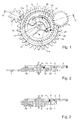
- FIGS. 1 and 2 a first embodiment of an inverter mechanism according to the invention, which will be illustrated by way of example by an automatic winding mechanism of a watch, is described below.
- mechanical by an oscillating mass whose motor pinion 3 acts in one direction to drive the first mobile 1 of a reduction kinematic chain (not shown) whose last mobile is in engagement with the barrel ratchet.
- the driving gear 3 of the oscillating weight meshes with a first driving gear 5 mounted idly on an axis of rotation 6 pivoted between a plate and a bridge (not shown), or between any other frame for positioning the parts of a mechanism watchmaker to each other.
- a second driven wheel 7 is positioned below the driving wheel 5 while being also mounted idle on the axis of rotation 6. It also has a toothing engaged with the first mobile 1 of the drive train.
- the driven wheel 7 comprises a bowl 11 whose opening is oriented towards the driving wheel 5.
- This bowl 11 is intended to house a clutch device 10 whose Embodiment is described below.
- the clutch device 10 basically comprises two parts, which can be made in one piece, or constitute two separate parts.
- the first part is constituted by a locking arm 12 which, in this embodiment, is curved, one end 14, designated “foot”, has a pivot point 14a in the drive wheel 5, for example around an axis 24 driven into said wheel.
- the other end 16 of the arm 12, designated “head”, provides a fulcrum 16a against the inner wall 2 of the bowl 11.
- This support is provided by a spring 20 connecting the head 16 and an attachment point 22 in the drive wheel 5.
- This spring 20 has been shown with a shape of circular arc between its two junction points, but it is obvious that it could have a completely different outline depending on the construction requirements, without departing from the scope of the present invention.
- the angle formed by the axis 6 with the pivot point 14a and the fulcrum 16a is an obtuse angle, slightly less than 180 °, making the arm allows the free rotation of the driving wheel 5 in one direction, without driving the driven wheel 7, and instead drives the driven wheel 7 when the driving wheel 5 rotates in the other direction, as will be described in more detail in reference to the second embodiment.
- the sectional representation of FIG. 3 concerns a variant of the first embodiment concerning the location of the power take-offs on the driving wheel 5 and on the driven wheel 7.
- the essential thing is that the driving wheel 5 and the driven wheel 7 are free to rotate relative to each other when the clutch mechanism 10 does not intervene.
- the driven wheel 7 no longer has toothing but is driven on an additional pinion 8, itself secured to the axis 6, while the driving wheel 5 remains mounted mad on said axis 6.
- the first mobile 1 of the kinematic chain then meshes with the additional pinion 8.
- the additional pinion 8 could be made integral with the driving wheel 5, being or not driven on the axis 6, the driven wheel 7 while being mounted mad on said axis 6.
- FIGS. 4 and 5 a second embodiment which differs from that previously described by the arrangement of the clutch device 10 is described below.
- the joint construction details will therefore not be further described and will the same references.
- the foot 14 of the locking arm 12 is no longer pivoted in the drive wheel 5, but its pivot point 14b can move on the edge of a guide cam 21, constituted by a plate secured to the driving wheel 5, for example by means of two pins 23.
- the spring 20 connects the head 16 and the cam 21 to maintain the fulcrum 16a in contact with the wall 2 of the bowl 11.
- the contour of the cam 21 is designed to minimize the "dead angle", ie the angle that the driving wheel 5 must travel before driving the driven wheel 7. With the clutch device according to the invention, this blind spot is reduced to a value less than 2 ° whereas it is of the order of 26 ° in the reversing mechanisms of the prior art.
- the curvature of the cam is for example of the exponential type, but other choices within the reach of the skilled person are possible.
- the operation of this clutch mechanism is explained later after the description of a first variant of this second mode.
- Figure 6 is a simplified representation of a first variant of the second embodiment.
- the head 16 of the locking arm 12 is extended, opposite the junction with the spring 20, by a guide extension 13 forming a third bearing point 13a on the wall 2 of the bowl 11 to better control the positioning of the locking fulcrum 16a.
- This variant will be taken up later to better understand the operation of the inverter mechanism according to the invention.
- FIG. 7 is a simplified representation of a second variant which differs from the preceding variant in that the guide extension 13 is no longer guided by the wall 2 of the bowl 11 but by a guide plate 26 situated in the cup 11, below the drive wheel 5 and secured thereto for example by means of pins 28.
- FIG 8 is a simplified representation of a third variant which can also integrate one or the other of the two previous variants.
- a safety device is provided to prevent the pivot point 14b from coming out of the cam 21 in the event of strong deflections of the driving wheel 5.
- This safety device consists, in the example represented, in a spout 15 , formed from the foot 14 of the locking arm 12, which cooperates with a recess 25 formed in an extension of the plate forming the cam 21.
- the skilled person can obviously design another arrangement of this safety device, without leaving of the scope of the present invention.
- Figure 9 is a simplified representation of a fourth variant which can also integrate the previous variants.
- the center of gravity of a moving part it is desirable for the center of gravity of a moving part to coincide with its axis of rotation in order to avoid an unbalance that is unfavorable to the efficiency of the device.
- the center of gravity of the assembly forming the clutch device 10 can not coincide with the axis of rotation 6.
- This fourth variant makes it possible to remedy this disadvantage by providing at least one balancing extension 17 whose geometry is calculated to bring into coincidence the center of gravity of the clutch device 10 and the center of the axis of rotation 6.
- the clutch device that has just been described, according to one or other of the embodiments, is a one-piece device made of a material that must have a certain elasticity because of the spring 20. It can be made of metal or alloy by known methods of micromachining, such as laser cutting, wire EDM, or by methods used for the manufacture of MEMs, such as the LIGA technique.
- the material used may also be non-metallic such as silicon, silicon dioxide, glass, or other silicon compounds, quartz or diamond using, for example, masking and etching methods to obtain the desired contour. These methods of manufacture are well known to those skilled in the art and therefore will not be described further.
- FIG. 10 corresponds to the clutch device 10, after fixing of the guide cam 21 in the driving wheel 5 by means of the pegs 23, but before final positioning in the bowl 11 of the driven wheel 7.
- the foot 14 of the arm 12 is not in contact with the cam 21, and the head 16 and the end of the guide extension 13 extend beyond the inner wall 2 of the bowl 11.
- the spring 20 will force the head 16 and the guide extension 13 to bear against the inner wall 11a of the bowl 11.
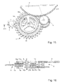
- FIGS. 13 to 16 a third and fourth embodiment is described below relating to a "two-way" reversing mechanism which basically consists in coupling a first single-direction reversing mechanism, whose references will be followed by the letter "a” and a second simple meaning mechanism whose references will be followed by the letter "b".
- the two reversing mechanisms are located in the same plane, the driving wheels 5a, 5b both meshing with the driving pinion 3, the driven wheels 7a, 7b meshing with each other.
- the clutch devices 10a, 10b are arranged in their respective cups 11a, 11b to have opposite actions.
- the clutch devices 10a, 10b are mirror images of each other. It is quite obvious, without departing from the scope of the invention, that other arrangements are possible, for example by using a deflection wheel which would make it possible to dispose them again either in a planar manner or superimposed way, the devices of clutch 10a, 10b then having the same orientation.
- FIG. 13 is represented by a solid line arrow in the direction of rotation of the mobiles when the alternation of the motor pinion 3 is effected in the clockwise direction, and by a double-pointed arrow when the alternation is effected. in the opposite direction.
- the pinion 3 drives the driving wheel 5b, which in turn causes the driven wheel 7b to lock, which itself drives the first pinion 1 of the drive train in a clockwise direction.
- the driven wheel 7b also meshes with the driven wheel 7b and is indeed not impeded in rotation by the driving wheel 5a, which is also rotated by the driving pinion 3, but which rotates in the opposite direction to the driving wheel 5a. by being free in rotation.
- FIGS 15 and 16 describe a fourth embodiment, which may also be understood as an alternative of the previous embodiment when the two clutch mechanisms are superimposed.
- the motor pinion 3 meshes with the driving wheel 5a of the first clutch mechanism and, via a return 4, with the driving wheel 5b of the second clutch mechanism.
- This fourth embodiment is characterized in that the driven wheels 7a and 7b form a junction plate 9 in which are formed on both sides the cups 11a, 11b intended to receive the mechanisms 10a, 10b, which in this case have the same orientation, but allow to have actions reversed because of the referral 4. The operation will not be explained because it follows naturally from what has been said for the third embodiment.
- Such an inverter mechanism can be used in a very small portable device to supply its source of mechanical or electrical energy, such as a wristwatch, when the drive pinion is driven by an oscillating mass. It can also find other applications, for example for the winding stem by providing a gear bevel gear.
- the invention is not limited to the embodiments that have just been described, since the person skilled in the art can adapt them as needed, for example for a particular watch gauge, or for a non-watchmaking application.
Abstract
Description
La présente invention a pour objet un mécanisme inverseur qui permet d'entraîner le premier mobile d'une chaîne cinématique dans un seul sens, quel que soit le sens de rotation du pignon d'entraînement. De tels dispositifs inverseurs sont notamment utilisés pour le remontage automatique du ressort de barillet d'une montre mécanique, ou pour entraîner la génératrice d'un quelconque petit appareil électronique portable, le pignon d'entraînement étant généralement mis en mouvement par une masse oscillante.The present invention relates to an inverter mechanism that allows to drive the first mobile of a kinematic chain in one direction, regardless of the direction of rotation of the drive pinion. Such inverter devices are used in particular for the automatic winding of the mainspring of a mechanical watch, or to drive the generator of any small portable electronic device, the drive gear being generally set in motion by an oscillating mass.
De nombreux dispositifs de remontage automatique par masse oscillante et mécanisme inverseur ont déjà été proposés. Ces dispositifs reposent sur les principes de mécanismes à cames ou à leviers-cliquets, de mécanismes à changement d'engrenage sur deux roues en prise, dont une seule est motrice, ou de mécanismes à galets, comme décrit par exemple dans le brevet
La présente invention vise donc à pallier les inconvénients de l'art antérieur précité en procurant un mécanisme inverseur comportant un plus petit nombre de pièces à assembler et pouvant donc être produit à moindre coût, tout en ayant des performances supérieures ou égales à celles des dispositifs de l'art antérieur.The present invention therefore aims to overcome the drawbacks of the aforementioned prior art by providing an inverter mechanism comprising a smaller number of parts to be assembled and can therefore be produced at lower cost, while having greater or equal performance than the devices of the prior art.
A cet effet le mécanisme inverseur, interposé entre la première roue d'une chaîne cinématique devant être entraînée dans un seul sens et le pignon moteur à mouvement alternatif, comprend une roue menante en prise avec ledit pignon moteur, montée sur un axe de rotation au dessus d'une roue menée montée sur le même axe et en prise, directement ou indirectement avec la première roue de la chaîne cinématique. La roue menée comporte une cuvette ouverte vers la roue menante pour loger un dispositif d'embrayage, réalisé en un matériaux élastique, permettant de coupler/découpler les deux roues en fonction du sens de rotation du pignon moteur. Le dispositif d'embrayage est caractérisé en ce qu'il comporte au moins un bras de blocage recourbé dont une extrémité a un point de pivotement sur la roue menante et dont l'autre extrémité a un point d'appui contre la paroi interne de la cuvette de la roue menée sous l'action d'un ressort venant de matière avec ledit bras.For this purpose the reversing mechanism, interposed between the first wheel of a kinematic chain to be driven in one direction and the reciprocating motor pinion, comprises a driving wheel engaged with said motor pinion mounted on an axis of rotation at above a driven wheel mounted on the same axis and engaged, directly or indirectly with the first wheel of the driveline. The driven wheel comprises a bowl open towards the driving wheel to house a clutch device, made of a resilient material, for coupling / uncoupling the two wheels depending on the direction of rotation of the motor pinion. The clutch device is characterized in that it comprises at least one arm of recurve lock, one end of which has a point of pivoting on the drive wheel and the other end of which has a fulcrum against the inner wall of the bowl of the wheel driven under the action of a spring coming from material with said arms.
Selon un premier mode de réalisation, le pivotement du bras s'effectue autour d'un axe fixe solidaire de la roue menante, et selon un deuxième mode de réalisation, qui sera expliqué plus en détails plus loin, le point de pivotement peut se déplacer le long d'une came solidaire de la roue menante.According to a first embodiment, the pivoting of the arm takes place around a fixed axis integral with the driving wheel, and according to a second embodiment, which will be explained in more detail later, the pivot point can move along a cam integral with the driving wheel.
Dans ce mécanisme "simple sens", et notamment dans le deuxième mode de réalisation, le fonctionnement peut encore être amélioré en prévoyant au niveau du bras de blocage une extension de guidage procurant un troisième point de positionnement dudit bras de blocage, une extension d'équilibrage permettant de réduire, voire de supprimer le balourd, et/ou un dispositif de sécurité limitant la course du point de pivotement le long de la came en cas de débattements trop violents.In this "one-way" mechanism, and particularly in the second embodiment, the operation can be further improved by providing at the level of the locking arm a guide extension providing a third positioning point of said locking arm, an extension of balancing to reduce or even eliminate the unbalance, and / or a safety device limiting the stroke of the pivot point along the cam in case of too violent deflections.
Le mécanisme inverseur brièvement décrit ci-dessus est dit "simple sens" car il n'est moteur que pour une seule alternance du pignon d'entraînement. Il est toutefois possible d'avoir un dispositif inverseur "double sens" en couplant deux mécanismes inverseurs "simple sens" ayant des dispositifs d'embrayage inversés. Dans un mode de réalisation préféré, les deux mécanismes inverseurs sont superposés et les deux roues menées ne forment qu'une seule pièce.The inverter mechanism briefly described above is called "one way" because it is only motor for a single alternation of the drive sprocket. It is possible, however, to have a "two-way" reversing device by coupling two "one-way" reversing mechanisms with inverted clutch devices. In a preferred embodiment, the two reversing mechanisms are superimposed and the two driven wheels form a single piece.
D'autres caractéristiques et avantages de la présente invention apparaîtront dans la description suivante de divers modes de réalisation, donnés à titre illustratif et non limitatif, en référence aux dessins annexés dans lesquels :
- la figure 1 est une vue en perspective d'un premier mode de réalisation;
- la figure 2 est une coupe brisée selon la ligne II-II de la figure 1;
- la figure 3 est une représentation en coupe d'une variante du premier mode de réalisation;
- la figure 4 est une vue en perspective d'un deuxième mode de réalisation;
- la figure 5 est une coupe brisée selon la ligne V-V de la figure 4;
- la figure 6 représente en perspective une première variante du deuxième mode de réalisation;
- la figure 7 représente en perspective une deuxième variante du deuxième mode de réalisation;
- la figure 8 représente en perspective une troisième variante du deuxième mode de réalisation;
- la figure 9 représente en perspective une quatrième variante du deuxième mode de réalisation;
- la figure 10 représente en vue de dessus simplifiée le dispositif d'embrayage avant montage;
- la figure 10A représente un détail de construction de la figure 10;
- les figures 11 et 12 permettent d'expliquer le fonctionnement du mécanisme inverseur;
- la figure 13 est une vue en perspective d'un troisième mode de réalisation;
- la figure 14 est une coupe brisée selon la ligne XIV-XIV de la figure 13;
- la figure 15 est une vue en perspective d'un quatrième mode de réalisation, et
- la figure 16 est une coupe brisée selon la ligne XVI-XVI de la figure 15.
- Figure 1 is a perspective view of a first embodiment;
- Figure 2 is a broken section along the line II-II of Figure 1;
- Figure 3 is a sectional representation of a variant of the first embodiment;
- Figure 4 is a perspective view of a second embodiment;
- Figure 5 is a broken section along the line VV of Figure 4;
- Figure 6 shows in perspective a first variant of the second embodiment;
- Figure 7 shows in perspective a second variant of the second embodiment;
- Figure 8 shows in perspective a third variant of the second embodiment;
- Figure 9 shows in perspective a fourth variant of the second embodiment;
- Figure 10 shows a simplified top view of the clutch device before assembly;
- Fig. 10A shows a constructional detail of Fig. 10;
- Figures 11 and 12 explain the operation of the inverter mechanism;
- Fig. 13 is a perspective view of a third embodiment;
- Figure 14 is a broken section along the line XIV-XIV of Figure 13;
- FIG. 15 is a perspective view of a fourth embodiment, and
- Figure 16 is a broken section along line XVI-XVI of Figure 15.
En se référant d'abord aux figures 1 et 2, on décrit ci-après un premier mode de réalisation d'un mécanisme inverseur selon l'invention, qui sera illustré à titre d'exemple par un mécanisme de remontage automatique d'une montre mécanique par une masse oscillante dont le pignon moteur 3 agit dans un seul sens pour entraîner le premier mobile 1 d'une chaîne cinématique de réduction (non représentée) dont le dernier mobile est en prise avec le rochet du barillet.Referring first to FIGS. 1 and 2, a first embodiment of an inverter mechanism according to the invention, which will be illustrated by way of example by an automatic winding mechanism of a watch, is described below. mechanical by an oscillating mass whose
Le pignon moteur 3 de la masse oscillante engrène avec une première roue dentée menante 5 montée folle sur un axe de rotation 6 pivoté entre une platine et un pont (non représentés), ou entre toute autre armature permettant de positionner les pièces d'un mécanisme horloger les unes par rapport aux autres.The
Une deuxième roue menée 7 est positionnée en dessous de la roue menante 5 en étant également montée folle sur l'axe de rotation 6. Elle comporte également une denture en prise avec le premier mobile 1 de la chaîne cinématique.A second driven
En se référant maintenant à la coupe de la figure 2, on voit que la roue menée 7 comporte une cuvette 11 dont l'ouverture est orientée vers la roue menante 5. Cette cuvette 11 est destinée à loger un dispositif d'embrayage 10 dont le mode de réalisation est décrit ci-après.Referring now to the section of FIG. 2, it can be seen that the driven
Le dispositif d'embrayage 10, comporte fondamentalement deux parties, pouvant être réalisées en une seule pièce, ou constituer deux pièces séparées.The
La première partie est constituée par un bras de blocage 12 qui, dans ce mode de réalisation, est recourbé, dont une extrémité 14, désignée par "pied", comporte un point de pivotement 14a dans la roue menante 5, par exemple autour d'un axe 24 chassé dans ladite roue. L'autre extrémité 16 du bras 12, désignée par "tête", procure un point d'appui 16a contre la paroi interne 2 de la cuvette 11. Cet appui est assuré par un ressort 20 reliant la tête 16 et un point de fixation 22 dans la roue menante 5. Ce ressort 20 a été représenté avec une forme en arc de cercle entre ses deux points de jonction, mais il est bien évident qu'il pourrait avoir un tout autre contour en fonction des impératifs de construction, sans sortir du cadre de la présente invention.The first part is constituted by a
Comme on peut le voir sur la représentation en perspective de la figure 1, l'angle formé par l'axe 6 avec le point de pivotement 14a et le point d'appui 16a est un angle obtus, légèrement inférieur à 180°, faisant que le bras permet la libre rotation de la roue menante 5 dans un sens, sans entraîner la roue menée 7, et entraîne au contraire la roue menée 7 lorsque la roue menante 5 tourne dans l'autre sens, comme cela sera décrit plus en détails en référence au deuxième mode de réalisation.As can be seen in the perspective view of FIG. 1, the angle formed by the
La représentation en coupe de la figure 3 concerne une variante du premier mode de réalisation concernant l'emplacement des prises de force sur la roue menante 5 et sur la roue menée 7. Comme on peut le comprendre, l'essentiel est que la roue menante 5 et la roue menée 7 soient libres en rotation l'une par rapport à l'autre lorsque le mécanisme d'embrayage 10 n'intervient pas. Dans l'exemple représenté la roue menée 7 ne comporte plus de denture mais elle est chassée sur un pignon additionnel 8, lui-même solidaire de l'axe 6, tandis que la roue menante 5 reste montée folle sur ledit axe 6. Le premier mobile 1 de la chaîne cinématique engrène alors avec le pignon additionnel 8. De façon équivalente (non représentée) le pignon additionnel 8 pourrait être rendu solidaire de la roue menante 5, en étant ou non chassé sur l'axe 6, la roue menée 7 étant alors montée folle sur ledit axe 6. Ces variantes de construction peuvent être simplement imposées par l'espace devant être réservé aux autres mobiles du mouvement horloger.The sectional representation of FIG. 3 concerns a variant of the first embodiment concerning the location of the power take-offs on the
En se référant maintenant aux figures 4 et 5, on décrit ci-après un deuxième mode de réalisation qui diffère de celui précédemment décrit par l'agencement du dispositif d'embrayage 10. Les détails de construction communs ne seront donc pas davantage décrits et porteront les mêmes références.Referring now to FIGS. 4 and 5, a second embodiment which differs from that previously described by the arrangement of the
Comme on peut le voir sur la figure 4, le pied 14 du bras de blocage 12 n'est plus pivoté dans la roue menante 5, mais son point de pivotement 14b peut se déplacer sur le bord d'une came de guidage 21, constituée par une plaque rendue solidaire de la roue menante 5, par exemple au moyen de deux chevilles 23. Le ressort 20 relie la tête 16 et la came 21 pour maintenir le point d'appui 16a en contact avec la paroi 2 de la cuvette 11. Le contour de la came 21 est conçu pour réduire au minimum "l'angle mort", c'est à dire l'angle que doit parcourir la roue menante 5 avant d'entraîner la roue menée 7. Avec le dispositif d'embrayage selon l'invention, cet angle mort est réduit à une valeur inférieure à 2° alors qu'elle est de l'ordre de 26° dans les mécanismes inverseurs de l'art antérieur.As can be seen in Figure 4, the
La courbure de la came est par exemple de type exponentiel, mais d'autres choix à la portée de l'homme de métier sont possibles. Le fonctionnement de ce mécanisme d'embrayage est expliqué plus loin après la description d'une première variante de ce deuxième mode.The curvature of the cam is for example of the exponential type, but other choices within the reach of the skilled person are possible. The operation of this clutch mechanism is explained later after the description of a first variant of this second mode.
La figure 6 est une représentation simplifiée d'une première variante du deuxième mode de réalisation. Comme on peut le voir la tête 16 du bras de blocage 12 est prolongée, à l'opposé de la jonction avec le ressort 20, par une extension de guidage 13 formant un troisième point d'appui 13a sur la paroi 2 de la cuvette 11 permettant de mieux contrôler le positionnement du point d'appui de blocage 16a. Cette variante sera reprise plus loin pour mieux faire comprendre le fonctionnement du mécanisme inverseur selon l'invention.Figure 6 is a simplified representation of a first variant of the second embodiment. As can be seen the
La figure 7 est une représentation simplifiée d'une deuxième variante qui diffère de la variante précédente en ce que l'extension de guidage 13 n'est plus guidée par la paroi 2 de la cuvette 11 mais par une plaque de guidage 26 située dans la cuvette 11, en dessous de la roue menante 5 et solidaire de celle-ci par exemple au moyen de chevilles 28.FIG. 7 is a simplified representation of a second variant which differs from the preceding variant in that the
La figure 8 est une représentation simplifiée d'une troisième variante qui peut également intégrer l'une ou l'autre des deux variantes précédentes. Dans cette variante un dispositif de sécurité est prévu pour éviter que le point de pivotement 14b ne sorte de la came 21 en cas de forts débattements de la roue menante 5. Ce dispositif de sécurité consiste, dans l'exemple représenté, en un bec 15, formé à partir du pied 14 du bras de blocage 12, qui coopère avec un décrochement 25 formé dans un prolongement de la plaque formant la came 21. L'homme de métier peut évidemment concevoir un autre agencement de ce dispositif de sécurité, sans sortir du cadre de la présente invention.Figure 8 is a simplified representation of a third variant which can also integrate one or the other of the two previous variants. In this variant a safety device is provided to prevent the
La figure 9 est une représentation simplifiée d'une quatrième variante qui peut également intégrer les variantes précédentes. De façon connue, il est souhaitable que le centre de gravité d'une pièce en mouvement coïncide avec son axe de rotation pour éviter un balourd défavorable au rendement du dispositif. Or, dans les constructions qui viennent d'être décrites, il est clair que le centre de gravité de l'ensemble formant le dispositif d'embrayage 10 ne peut pas coïncider avec l'axe de rotation 6. Cette quatrième variante permet de remédier à cet inconvénient en prévoyant au moins une extension d'équilibrage 17 dont la géométrie est calculée pour amener en coïncidence le centre de gravité du dispositif d'embrayage 10 et le centre de l'axe de rotation 6. Selon la forme du bras de blocage 12, il est également possible de prévoir plus d'une extension d'équilibrage.Figure 9 is a simplified representation of a fourth variant which can also integrate the previous variants. In a known manner, it is desirable for the center of gravity of a moving part to coincide with its axis of rotation in order to avoid an unbalance that is unfavorable to the efficiency of the device. However, in the constructions which have just been described, it is clear that the center of gravity of the assembly forming the
Le dispositif d'embrayage qui vient d'être décrit, selon l'un ou l'autre des modes de réalisation est un dispositif monobloc réalisé en un matériau devant présenter une certaine élasticité en raison du ressort 20. Il peut être fabriqué en métal ou alliage par des méthodes connues de micro-usinage, telles que le découpage par laser, l'électroérosion à fil, ou par des méthodes utilisées pour la fabrication de MEMs, telle que la technique LIGA. Le matériau utilisé peut également être non métallique tel que le silicium, le dioxyde de silicium, le verre, ou autres composés du silicium, le quartz ou le diamant en utilisant par exemple les méthodes de masquage et attaque chimique pour obtenir le contour désiré. Ces méthodes de fabrication sont bien connues de l'homme de l'art et ne seront donc pas décrites davantage.The clutch device that has just been described, according to one or other of the embodiments, is a one-piece device made of a material that must have a certain elasticity because of the
On se réfère maintenant aux figures 10, 11, 12 pour expliquer le fonctionnement du mécanisme inverseur précédemment décrit dans la variante correspondant à la figure 6.Referring now to Figures 10, 11, 12 to explain the operation of the inverter mechanism previously described in the variant corresponding to Figure 6.
La figure 10 correspond au dispositif d'embrayage 10, après fixation de la came de guidage 21 dans la roue menante 5 au moyen des chevilles 23, mais avant la mise en place définitive dans la cuvette 11 de la roue menée 7. Comme on peut le voir, le pied 14 du bras 12 n'est pas en contact avec la came 21, et la tête 16 ainsi que l'extrémité de l'extension de guidage 13 s'étendent au-delà de la paroi interne 2 de la cuvette 11. Au montage définitif le ressort 20 forcera la tête 16 et l'extension guidage 13 à venir en appui contre la paroi interne 11a de la cuvette 11.FIG. 10 corresponds to the
Pour faciliter la manipulation avant montage et éviter de déformer le dispositif d'embrayage 10 en dehors du plan, il peut être prévu lors de la fabrication, comme représenté à la figure 10A, de former un pont de matière 18 entre le pied 14 et la came 21, ledit pont 18 étant alors détruit juste avant mise en place définitive.To facilitate handling before mounting and avoid deforming the
La figure 11 représente le même dispositif d'embrayage, après montage lorsque le dispositif est entraînée en rotation "sens libre", c'est-à-dire lorsque la roue menante 5 tourne dans le sens horaire indiquée par la flèche au centre, sans entraîner la roue menée 7. En effet la pression exercée par la tête 16 du bras de blocage 12 et par l'extension de guidage 13 (représentée par les petites flèches) sur la paroi interne 2 de la cuvette 11 n'est pas suffisante et permet seulement un glissement des points de contact le long de ladite paroi interne 2.FIG. 11 shows the same clutch device, after assembly when the device is driven in "free direction" rotation, that is to say when the
Inversement, comme représenté à la figure 12, lorsque la roue menante 5 tourne dans le sens antihoraire indiqué par la flèche au centre, la pression exercée par la tête 16 est suffisante pour provoquer un blocage et entraîner la roue menée 7. Comme on peut le voir, l'extrémité de l'extension de guidage s'écarte légèrement de la paroi 2 de la cuvette 11, cet écart étant exagéré sur la figure 12. De même le point de contact du pied 14 se déplace légèrement le long de la came 21 en sens inverse du sens de rotation de la roue menante 5 pour augmenter l'effet de blocage.Conversely, as shown in FIG. 12, when the
En se référant maintenant aux figures 13 à 16, on décrit ci-après un troisième et un quatrième mode de réalisation concernant un mécanisme inverseur "double sens" qui consiste fondamentalement à coupler un premier mécanisme inverseur simple sens, dont les références seront suivies de la lettre "a" et un deuxième mécanisme simple sens dont les références seront suivie de la lettre "b".Referring now to FIGS. 13 to 16, a third and fourth embodiment is described below relating to a "two-way" reversing mechanism which basically consists in coupling a first single-direction reversing mechanism, whose references will be followed by the letter "a" and a second simple meaning mechanism whose references will be followed by the letter "b".
Selon le troisième mode de réalisation, représenté aux figures 13 et 14, les deux mécanismes inverseurs sont situés dans un même plan, les roues menantes 5a, 5b engrènent toutes deux avec le pignon d'entraînement 3, les roues menées 7a, 7b engrènent l'une avec l'autre et les dispositifs d'embrayage 10a, 10b sont disposés dans leurs cuvettes respectives 11 a, 11 b pour avoir des actions opposées. Dans cette construction les dispositifs d'embrayage 10a, 10b sont des images de miroir l'une de l'autre. Il est bien évident, sans sortir du cadre de l'invention, que d'autres agencements sont possibles, par exemple en utilisant une roue de renvoi qui permettrait de les disposer encore soit de façon planaire, soit de façon superposée, les dispositifs d'embrayage 10a, 10b ayant alors la même orientation.According to the third embodiment, represented in FIGS. 13 and 14, the two reversing mechanisms are located in the same plane, the
Sur la figure 13 on a représenté par une flèche en trait plein le sens de rotation des mobiles lorsque l'alternance du pignon moteur 3 s'effectue dans le sens horaire, et par une flèche à doubles traits, lorsque l'alternance s'effectue en sens contraire.FIG. 13 is represented by a solid line arrow in the direction of rotation of the mobiles when the alternation of the
Lorsque l'alternance s'effectue dans le sens horaire, le pignon 3 entraîne la roue menante 5b qui entraîne à son tour par blocage la roue menée 7b, qui elle même entraîne le premier pignon 1 de la chaîne cinématique dans le sens horaire. La roue menée 7b engrène également avec la roue menée 7b et n'est en effet pas gênée en rotation par la roue menante 5a, qui est entraînée en rotation également par le pignon moteur 3, mais qui tourne en sens inverse de la roue menante 5a en étant libre en rotation.When the alternation is carried out in the clockwise direction, the
Lorsque le pignon d'entraînement 3 a une alternance inverse en sens antihoraire, on voit que le premier mobile 1 de la chaîne cinématique est toujours entraîné dans le même sens par la roue menée 7b, elle-même entraînée par la roue menée 7a, elle-même entraînée par blocage par la roue menante 5a, la roue menante 5b du deuxième mécanisme 10b étant libre en rotation par rapport à la roue menante 7b.When the
Les figures 15 et 16 permettent de décrire un quatrième mode de réalisation, qui peut également être compris comme une variante du mode de réalisation précédent lorsque les deux mécanismes d'embrayage sont superposés. Comme on peut le voir, le pignon moteur 3 engrène avec la roue menante 5a du premier mécanisme d'embrayage et, par l'intermédiaire d'un renvoi 4, avec la roue menante 5b du deuxième mécanisme d'embrayage. Ce quatrième mode de réalisation est caractérisé par le fait que les roues menées 7a et 7b forment un plateau de jonction 9 dans lequel sont formées de part et d'autre les cuvettes 11 a, 11 b destinées à recevoir les mécanismes 10a, 10b, qui dans ce cas ont la même orientation, mais permettent d'avoir des actions inversées en raison du renvoi 4. Le fonctionnement ne sera pas expliqué car il découle naturellement de ce qui a été dit pour le troisième mode de réalisation.Figures 15 and 16 describe a fourth embodiment, which may also be understood as an alternative of the previous embodiment when the two clutch mechanisms are superimposed. As can be seen, the
Un tel mécanisme inverseur peut être utilisé dans un tout petit appareil portable pour alimenter sa source d'énergie mécanique ou électrique, tel qu'une montre-bracelet, lorsque le pignon moteur est entraîné par une masse oscillante. Il peut également trouver d'autres applications, par exemple pour la tige de remontoir en prévoyant un engrenage à pignons coniques.Such an inverter mechanism can be used in a very small portable device to supply its source of mechanical or electrical energy, such as a wristwatch, when the drive pinion is driven by an oscillating mass. It can also find other applications, for example for the winding stem by providing a gear bevel gear.
L'invention n'est pas limitée aux modes de réalisation qui viennent d'être décrits car l'homme de métier peut les adapter en fonction des besoins, par exemple pour un calibre particulier de montre, ou pour une application non horlogèreThe invention is not limited to the embodiments that have just been described, since the person skilled in the art can adapt them as needed, for example for a particular watch gauge, or for a non-watchmaking application.
Claims (19)
Priority Applications (7)
| Application Number | Priority Date | Filing Date | Title |
|---|---|---|---|
| ES06007364T ES2327350T3 (en) | 2006-04-07 | 2006-04-07 | INVESTING MECHANISM FOR UNIDIRECTIONAL ROTARY DRIVING OF A MOBILE. |
| EP06007364A EP1843225B1 (en) | 2006-04-07 | 2006-04-07 | Mechanical reverser for rotational and unidirectional driving of a wheel |
| DE602006007807T DE602006007807D1 (en) | 2006-04-07 | 2006-04-07 | Mechanical changer for rotating a wheel from a single direction |
| US11/695,701 US7287901B1 (en) | 2006-04-07 | 2007-04-03 | Reverser mechanism for uni-directional rotational driving of a wheel set |
| JP2007100392A JP5064084B2 (en) | 2006-04-07 | 2007-04-06 | Reverser mechanism for unidirectional rotational drive of wheel set |
| CN200710091100XA CN101051213B (en) | 2006-04-07 | 2007-04-09 | Reverser mechanism for uni-directional rotational driving of a wheel set |
| HK07113755.1A HK1108495A1 (en) | 2006-04-07 | 2007-12-18 | Reverser mechanism for uni-directional rotational driving of a wheel set |
Applications Claiming Priority (1)
| Application Number | Priority Date | Filing Date | Title |
|---|---|---|---|
| EP06007364A EP1843225B1 (en) | 2006-04-07 | 2006-04-07 | Mechanical reverser for rotational and unidirectional driving of a wheel |
Publications (2)
| Publication Number | Publication Date |
|---|---|
| EP1843225A1 true EP1843225A1 (en) | 2007-10-10 |
| EP1843225B1 EP1843225B1 (en) | 2009-07-15 |
Family
ID=37667079
Family Applications (1)
| Application Number | Title | Priority Date | Filing Date |
|---|---|---|---|
| EP06007364A Active EP1843225B1 (en) | 2006-04-07 | 2006-04-07 | Mechanical reverser for rotational and unidirectional driving of a wheel |
Country Status (7)
| Country | Link |
|---|---|
| US (1) | US7287901B1 (en) |
| EP (1) | EP1843225B1 (en) |
| JP (1) | JP5064084B2 (en) |
| CN (1) | CN101051213B (en) |
| DE (1) | DE602006007807D1 (en) |
| ES (1) | ES2327350T3 (en) |
| HK (1) | HK1108495A1 (en) |
Cited By (5)
| Publication number | Priority date | Publication date | Assignee | Title |
|---|---|---|---|---|
| EP2263825A1 (en) * | 2009-06-16 | 2010-12-22 | Blösch Ressourcen AG | Method for producing workpieces from a material board |
| WO2014180459A1 (en) * | 2013-05-06 | 2014-11-13 | Kiekert Aktiengesellschaft | Miniature drive for automobile locks with running direction lock |
| US9298163B2 (en) | 2013-11-06 | 2016-03-29 | Eta Sa Manufacture Horlogere Suisse | Timepiece wheel set with a unidirectional wheel |
| EP3705949A1 (en) * | 2019-03-05 | 2020-09-09 | ETA SA Manufacture Horlogère Suisse | Torque limiter mechanism for a timepiece |
| EP4198640A1 (en) | 2021-12-15 | 2023-06-21 | Richemont International S.A. | Planetary reverser and automatic winding mechanism for timepieces |
Families Citing this family (24)
| Publication number | Priority date | Publication date | Assignee | Title |
|---|---|---|---|---|
| DE102007046689B4 (en) * | 2007-06-01 | 2009-09-17 | Konrad Damasko | Mechanical lift for wristwatches and wristwatch with such a lift |
| EP2060534A1 (en) * | 2007-11-16 | 2009-05-20 | Nivarox-FAR S.A. | Composite silicon-metal micromechanical component and method for manufacturing same |
| EP2154582A1 (en) * | 2008-08-15 | 2010-02-17 | Nivarox-FAR S.A. | Gear method for a clock piece |
| ATE498860T1 (en) * | 2008-12-01 | 2011-03-15 | Swatch Group Res & Dev Ltd | CLOCK MOVEMENT EQUIPPED WITH A VIBRATION ALARM |
| ES2423285T3 (en) * | 2009-03-03 | 2013-09-19 | Montres Jaquet Droz Sa | Clutch release mechanism for clockwork, and clock movement comprising this device |
| EP2264550A1 (en) * | 2009-06-16 | 2010-12-22 | Samep S.A. - Montres Emile Pequignet | Wheel for a reverser device, method for manufacturing such a wheel and reverser devices for a timepiece movement comprising such a wheel |
| CH702924B1 (en) * | 2010-06-03 | 2011-10-14 | Patek Philippe Sa Geneve | Mobile-way clutch, winding mechanism and a timepiece including said mobile. |
| EP2397921B1 (en) * | 2010-06-17 | 2017-08-30 | Blancpain S.A. | Mechanism for a jumping tourbillon cage |
| CN103003758B (en) * | 2010-06-22 | 2015-08-12 | 斯沃奇集团研究和开发有限公司 | The method of the adjustment first component of mechanical component and the relative position of second component |
| EP2596406B1 (en) * | 2010-07-19 | 2019-03-27 | Nivarox-FAR S.A. | Oscillating mechanism with elastic pivot and mobile for the transmission of energy |
| EP2586879A1 (en) * | 2011-10-27 | 2013-05-01 | Nivarox-FAR S.A. | Method for thermal treatment of micromechanical clock parts |
| ES2623896T3 (en) * | 2014-01-15 | 2017-07-12 | Audemars Piguet (Renaud Et Papi) Sa | Inverter for watchmaking |
| EP3001257B1 (en) * | 2014-09-26 | 2018-01-17 | ETA SA Manufacture Horlogère Suisse | Paraxial, isochronous timepiece resonator |
| EP3009896B1 (en) * | 2014-10-17 | 2020-03-11 | Nivarox-FAR S.A. | Integral part made of electroformed metal |
| EP3018535B1 (en) * | 2014-11-07 | 2018-09-05 | Montres Breguet SA | Winding device with one-way drive arrangement |
| EP3021173B1 (en) * | 2014-11-14 | 2017-05-24 | Blancpain S.A. | Annular oscillating mass and timepiece comprising such an oscillating mass |
| EP3021174A1 (en) * | 2014-11-17 | 2016-05-18 | LVMH Swiss Manufactures SA | Monolithic timepiece regulator, timepiece movement and timepiece having such a timepiece regulator |
| EP3104232B1 (en) * | 2015-06-11 | 2017-11-29 | Société anonyme de la Manufacture d'Horlogerie Audemars Piguet & Cie | Timepiece reverser and self-winding watch comprising same |
| EP3163381B1 (en) * | 2015-10-26 | 2019-06-26 | The Swatch Group Research and Development Ltd. | Automatic winding of a watch |
| US10317842B2 (en) * | 2016-04-25 | 2019-06-11 | Seiko Epson Corporation | Timepiece mainspring, timepiece drive device, timepiece movement, timepiece, and manufacturing method of timepiece mainspring |
| CN106406066B (en) * | 2016-06-29 | 2018-07-20 | 辽宁孔雀表业有限公司 | A kind of external tooth planet gear type changement of automatic watch |
| CN106286636B (en) * | 2016-11-08 | 2018-08-07 | 天津铁路信号有限责任公司 | A kind of electric point machine roller Bidirectional non-return device |
| JP7023124B2 (en) * | 2018-01-26 | 2022-02-21 | セイコーインスツル株式会社 | Movement and watches |
| CN111449817B (en) * | 2020-04-21 | 2022-02-22 | 合肥瑞欣康复用品用具有限责任公司 | Production process and production line of orthotics |
Citations (7)
| Publication number | Priority date | Publication date | Assignee | Title |
|---|---|---|---|---|
| US2645319A (en) * | 1950-05-03 | 1953-07-14 | Robin Leo | Free wheel mechanism |
| CH305463A (en) | 1952-03-12 | 1955-02-28 | Chs Tissot & Fils S A | Self-winding watch with movements in both directions of rotation of a moving mass. |
| GB814535A (en) * | 1955-10-11 | 1959-06-10 | Otto Epple | Automatic winding device for watches, preferably for wrist-watches |
| CH400017A (en) * | 1963-12-24 | 1966-04-15 | Ebauches Sa | Self-winding clock with oscillating mass |
| CH412721A (en) * | 1961-07-06 | 1966-11-30 | Fontainemelon Horlogerie | Watch winder |
| JPS4718706U (en) | 1971-04-01 | 1972-11-01 | ||
| DE2851735A1 (en) * | 1978-11-30 | 1980-06-04 | Durowe Gmbh | Reverse rotation blocking device for watch self-winding mechanism - comprising roller slid into gap between relatively rotating parts |
Family Cites Families (10)
| Publication number | Priority date | Publication date | Assignee | Title |
|---|---|---|---|---|
| JPS5741751Y2 (en) * | 1977-10-15 | 1982-09-13 | ||
| JPS6138585U (en) * | 1984-08-10 | 1986-03-11 | 中川電化産業株式会社 | Ratchet mechanism |
| JPS61141822U (en) * | 1985-02-25 | 1986-09-02 | ||
| JPS62183853A (en) | 1986-02-07 | 1987-08-12 | Toyo C C I Kk | Carbon monoxide converting catalyst |
| US4809250A (en) * | 1988-01-29 | 1989-02-28 | Fabrique Ebel, Societe Anonyme | Reverser mechanism for an automatic winding arrangement |
| CN2121039U (en) * | 1992-04-29 | 1992-11-04 | 广州明珠表业有限公司 | Revrse mechanism of auto-watch |
| DE69919509T2 (en) * | 1999-04-23 | 2005-09-01 | Rolex Sa | Clockwork with inertia self-winding |
| EP1152303B1 (en) * | 2000-05-05 | 2006-07-19 | Rolex Sa | Timepiece with winding mechanism and mechanism for the correction of at least two indicating organs |
| CN1374570A (en) * | 2001-10-10 | 2002-10-16 | 刘越雄 | Double-lever interlocking change-over mechanism and method for automatic watch |
| JP2004170270A (en) * | 2002-11-20 | 2004-06-17 | Seiko Instruments Inc | Self-winding watch having adjusting apparatus |
-
2006
- 2006-04-07 ES ES06007364T patent/ES2327350T3/en active Active
- 2006-04-07 DE DE602006007807T patent/DE602006007807D1/en active Active
- 2006-04-07 EP EP06007364A patent/EP1843225B1/en active Active
-
2007
- 2007-04-03 US US11/695,701 patent/US7287901B1/en active Active
- 2007-04-06 JP JP2007100392A patent/JP5064084B2/en active Active
- 2007-04-09 CN CN200710091100XA patent/CN101051213B/en active Active
- 2007-12-18 HK HK07113755.1A patent/HK1108495A1/en unknown
Patent Citations (7)
| Publication number | Priority date | Publication date | Assignee | Title |
|---|---|---|---|---|
| US2645319A (en) * | 1950-05-03 | 1953-07-14 | Robin Leo | Free wheel mechanism |
| CH305463A (en) | 1952-03-12 | 1955-02-28 | Chs Tissot & Fils S A | Self-winding watch with movements in both directions of rotation of a moving mass. |
| GB814535A (en) * | 1955-10-11 | 1959-06-10 | Otto Epple | Automatic winding device for watches, preferably for wrist-watches |
| CH412721A (en) * | 1961-07-06 | 1966-11-30 | Fontainemelon Horlogerie | Watch winder |
| CH400017A (en) * | 1963-12-24 | 1966-04-15 | Ebauches Sa | Self-winding clock with oscillating mass |
| JPS4718706U (en) | 1971-04-01 | 1972-11-01 | ||
| DE2851735A1 (en) * | 1978-11-30 | 1980-06-04 | Durowe Gmbh | Reverse rotation blocking device for watch self-winding mechanism - comprising roller slid into gap between relatively rotating parts |
Cited By (8)
| Publication number | Priority date | Publication date | Assignee | Title |
|---|---|---|---|---|
| EP2263825A1 (en) * | 2009-06-16 | 2010-12-22 | Blösch Ressourcen AG | Method for producing workpieces from a material board |
| EP2263824A1 (en) * | 2009-06-16 | 2010-12-22 | BCI Blösch Corporation Inc. | Method for producing workpieces from a material board |
| WO2014180459A1 (en) * | 2013-05-06 | 2014-11-13 | Kiekert Aktiengesellschaft | Miniature drive for automobile locks with running direction lock |
| US10400859B2 (en) | 2013-05-06 | 2019-09-03 | Kiekert Aktiengesellschaft | Miniature drive for automobile locks with running direction lock |
| US9298163B2 (en) | 2013-11-06 | 2016-03-29 | Eta Sa Manufacture Horlogere Suisse | Timepiece wheel set with a unidirectional wheel |
| EP3705949A1 (en) * | 2019-03-05 | 2020-09-09 | ETA SA Manufacture Horlogère Suisse | Torque limiter mechanism for a timepiece |
| US11768464B2 (en) | 2019-03-05 | 2023-09-26 | Eta Sa Manufacture Horlogere Suisse | Horological torque limiting mechanism |
| EP4198640A1 (en) | 2021-12-15 | 2023-06-21 | Richemont International S.A. | Planetary reverser and automatic winding mechanism for timepieces |
Also Published As
| Publication number | Publication date |
|---|---|
| EP1843225B1 (en) | 2009-07-15 |
| CN101051213B (en) | 2010-04-14 |
| HK1108495A1 (en) | 2008-05-09 |
| DE602006007807D1 (en) | 2009-08-27 |
| US20070237035A1 (en) | 2007-10-11 |
| JP2007279045A (en) | 2007-10-25 |
| CN101051213A (en) | 2007-10-10 |
| JP5064084B2 (en) | 2012-10-31 |
| US7287901B1 (en) | 2007-10-30 |
| ES2327350T3 (en) | 2009-10-28 |
Similar Documents
| Publication | Publication Date | Title |
|---|---|---|
| EP1843225B1 (en) | Mechanical reverser for rotational and unidirectional driving of a wheel | |
| EP1918789B1 (en) | Oscillating mass to recharge the energy source of a portable instrument | |
| EP2583143B1 (en) | Mechanism for advancing a tourbillon cage or a karrusel cage by periodic jumps | |
| EP2376986B1 (en) | Horological movement with automatic winding and moving escapement | |
| WO2017102916A1 (en) | Mechanism for adjusting an average speed in a clock movement and clock movement | |
| EP3040783B1 (en) | Sub-assembly for a mechanism for adjusting a speed in a clock movement and such a mechanism | |
| EP2871537A1 (en) | Watch with improved power reserve | |
| EP1615085A1 (en) | Correction mechanism for the seating of a regulator device for balance-spring | |
| EP3382468B1 (en) | Movement with extension of running reserve | |
| EP3203326B1 (en) | Timepiece conversion mechanism of a rotary motion with any amplitude and direction into a one-way motion | |
| CH715052A2 (en) | Constant torque mechanism, timepiece movement, and timepiece. | |
| EP2054780A2 (en) | Control device for a timepiece | |
| EP2515185B1 (en) | Engine with constant torque | |
| EP2053474B1 (en) | Chronograph timepiece | |
| EP3779606A1 (en) | Self-winding watch | |
| EP3599514B1 (en) | Exhaust mechanism having bistable and monostable springs | |
| EP3707563A1 (en) | Driving member of a timepiece | |
| EP3783444B1 (en) | Timepiece mechanism comprising a locking device | |
| EP3557334A1 (en) | Escapement mechanism with lock pallet and timepiece comprising such an escapement mechanism | |
| EP3346342B1 (en) | Displacement conversion device | |
| CH713302A2 (en) | Device for converting displacements, for example for automatic winding systems of timepieces. | |
| EP1879085A1 (en) | Escapement | |
| CH717664A2 (en) | Timepiece comprising a waterproof control device. | |
| CH713407B1 (en) | Winding system for a timepiece. | |
| CH715969B1 (en) | Mechanism for generating a frictional force. |
Legal Events
| Date | Code | Title | Description |
|---|---|---|---|
| PUAI | Public reference made under article 153(3) epc to a published international application that has entered the european phase |
Free format text: ORIGINAL CODE: 0009012 |
|
| AK | Designated contracting states |
Kind code of ref document: A1 Designated state(s): AT BE BG CH CY CZ DE DK EE ES FI FR GB GR HU IE IS IT LI LT LU LV MC NL PL PT RO SE SI SK TR |
|
| AX | Request for extension of the european patent |
Extension state: AL BA HR MK YU |
|
| 17P | Request for examination filed |
Effective date: 20080410 |
|
| AKX | Designation fees paid |
Designated state(s): AT BE BG CH CY CZ DE DK EE ES FI FR GB GR HU IE IS IT LI LT LU LV MC NL PL PT RO SE SI SK TR |
|
| 17Q | First examination report despatched |
Effective date: 20080616 |
|
| GRAP | Despatch of communication of intention to grant a patent |
Free format text: ORIGINAL CODE: EPIDOSNIGR1 |
|
| GRAS | Grant fee paid |
Free format text: ORIGINAL CODE: EPIDOSNIGR3 |
|
| RIN1 | Information on inventor provided before grant (corrected) |
Inventor name: CONUS, THIERRY Inventor name: HELFER, JEAN-LUC |
|
| GRAA | (expected) grant |
Free format text: ORIGINAL CODE: 0009210 |
|
| AK | Designated contracting states |
Kind code of ref document: B1 Designated state(s): AT BE BG CH CY CZ DE DK EE ES FI FR GB GR HU IE IS IT LI LT LU LV MC NL PL PT RO SE SI SK TR |
|
| REG | Reference to a national code |
Ref country code: CH Ref legal event code: EP Ref country code: GB Ref legal event code: FG4D Free format text: NOT ENGLISH |
|
| REG | Reference to a national code |
Ref country code: CH Ref legal event code: NV Representative=s name: ICB INGENIEURS CONSEILS EN BREVETS SA |
|
| REG | Reference to a national code |
Ref country code: IE Ref legal event code: FG4D |
|
| REF | Corresponds to: |
Ref document number: 602006007807 Country of ref document: DE Date of ref document: 20090827 Kind code of ref document: P |
|
| REG | Reference to a national code |
Ref country code: ES Ref legal event code: FG2A Ref document number: 2327350 Country of ref document: ES Kind code of ref document: T3 |
|
| NLV1 | Nl: lapsed or annulled due to failure to fulfill the requirements of art. 29p and 29m of the patents act | ||
| REG | Reference to a national code |
Ref country code: AT Ref legal event code: UEP Ref document number: 436720 Country of ref document: AT Kind code of ref document: T |
|
| PG25 | Lapsed in a contracting state [announced via postgrant information from national office to epo] |
Ref country code: SE Free format text: LAPSE BECAUSE OF FAILURE TO SUBMIT A TRANSLATION OF THE DESCRIPTION OR TO PAY THE FEE WITHIN THE PRESCRIBED TIME-LIMIT Effective date: 20090715 Ref country code: IS Free format text: LAPSE BECAUSE OF FAILURE TO SUBMIT A TRANSLATION OF THE DESCRIPTION OR TO PAY THE FEE WITHIN THE PRESCRIBED TIME-LIMIT Effective date: 20091115 Ref country code: LT Free format text: LAPSE BECAUSE OF FAILURE TO SUBMIT A TRANSLATION OF THE DESCRIPTION OR TO PAY THE FEE WITHIN THE PRESCRIBED TIME-LIMIT Effective date: 20090715 |
|
| REG | Reference to a national code |
Ref country code: IE Ref legal event code: FD4D |
|
| PG25 | Lapsed in a contracting state [announced via postgrant information from national office to epo] |
Ref country code: LV Free format text: LAPSE BECAUSE OF FAILURE TO SUBMIT A TRANSLATION OF THE DESCRIPTION OR TO PAY THE FEE WITHIN THE PRESCRIBED TIME-LIMIT Effective date: 20090715 Ref country code: PL Free format text: LAPSE BECAUSE OF FAILURE TO SUBMIT A TRANSLATION OF THE DESCRIPTION OR TO PAY THE FEE WITHIN THE PRESCRIBED TIME-LIMIT Effective date: 20090715 Ref country code: NL Free format text: LAPSE BECAUSE OF FAILURE TO SUBMIT A TRANSLATION OF THE DESCRIPTION OR TO PAY THE FEE WITHIN THE PRESCRIBED TIME-LIMIT Effective date: 20090715 Ref country code: SI Free format text: LAPSE BECAUSE OF FAILURE TO SUBMIT A TRANSLATION OF THE DESCRIPTION OR TO PAY THE FEE WITHIN THE PRESCRIBED TIME-LIMIT Effective date: 20090715 |
|
| PG25 | Lapsed in a contracting state [announced via postgrant information from national office to epo] |
Ref country code: PT Free format text: LAPSE BECAUSE OF FAILURE TO SUBMIT A TRANSLATION OF THE DESCRIPTION OR TO PAY THE FEE WITHIN THE PRESCRIBED TIME-LIMIT Effective date: 20091115 Ref country code: BG Free format text: LAPSE BECAUSE OF FAILURE TO SUBMIT A TRANSLATION OF THE DESCRIPTION OR TO PAY THE FEE WITHIN THE PRESCRIBED TIME-LIMIT Effective date: 20091015 |
|
| PG25 | Lapsed in a contracting state [announced via postgrant information from national office to epo] |
Ref country code: IE Free format text: LAPSE BECAUSE OF FAILURE TO SUBMIT A TRANSLATION OF THE DESCRIPTION OR TO PAY THE FEE WITHIN THE PRESCRIBED TIME-LIMIT Effective date: 20090715 Ref country code: DK Free format text: LAPSE BECAUSE OF FAILURE TO SUBMIT A TRANSLATION OF THE DESCRIPTION OR TO PAY THE FEE WITHIN THE PRESCRIBED TIME-LIMIT Effective date: 20090715 Ref country code: RO Free format text: LAPSE BECAUSE OF FAILURE TO SUBMIT A TRANSLATION OF THE DESCRIPTION OR TO PAY THE FEE WITHIN THE PRESCRIBED TIME-LIMIT Effective date: 20090715 Ref country code: CZ Free format text: LAPSE BECAUSE OF FAILURE TO SUBMIT A TRANSLATION OF THE DESCRIPTION OR TO PAY THE FEE WITHIN THE PRESCRIBED TIME-LIMIT Effective date: 20090715 Ref country code: EE Free format text: LAPSE BECAUSE OF FAILURE TO SUBMIT A TRANSLATION OF THE DESCRIPTION OR TO PAY THE FEE WITHIN THE PRESCRIBED TIME-LIMIT Effective date: 20090715 |
|
| PLBE | No opposition filed within time limit |
Free format text: ORIGINAL CODE: 0009261 |
|
| STAA | Information on the status of an ep patent application or granted ep patent |
Free format text: STATUS: NO OPPOSITION FILED WITHIN TIME LIMIT |
|
| PG25 | Lapsed in a contracting state [announced via postgrant information from national office to epo] |
Ref country code: SK Free format text: LAPSE BECAUSE OF FAILURE TO SUBMIT A TRANSLATION OF THE DESCRIPTION OR TO PAY THE FEE WITHIN THE PRESCRIBED TIME-LIMIT Effective date: 20090715 |
|
| 26N | No opposition filed |
Effective date: 20100416 |
|
| PG25 | Lapsed in a contracting state [announced via postgrant information from national office to epo] |
Ref country code: GR Free format text: LAPSE BECAUSE OF FAILURE TO SUBMIT A TRANSLATION OF THE DESCRIPTION OR TO PAY THE FEE WITHIN THE PRESCRIBED TIME-LIMIT Effective date: 20091016 |
|
| BERE | Be: lapsed |
Owner name: ETA SA MANUFACTURE HORLOGERE SUISSE Effective date: 20100430 |
|
| PG25 | Lapsed in a contracting state [announced via postgrant information from national office to epo] |
Ref country code: MC Free format text: LAPSE BECAUSE OF NON-PAYMENT OF DUE FEES Effective date: 20100430 |
|
| REG | Reference to a national code |
Ref country code: AT Ref legal event code: UEP Ref document number: 436720 Country of ref document: AT Kind code of ref document: T |
|
| PG25 | Lapsed in a contracting state [announced via postgrant information from national office to epo] |
Ref country code: BE Free format text: LAPSE BECAUSE OF NON-PAYMENT OF DUE FEES Effective date: 20100430 |
|
| PGFP | Annual fee paid to national office [announced via postgrant information from national office to epo] |
Ref country code: IT Payment date: 20110326 Year of fee payment: 6 Ref country code: FI Payment date: 20110324 Year of fee payment: 6 |
|
| PGFP | Annual fee paid to national office [announced via postgrant information from national office to epo] |
Ref country code: ES Payment date: 20110407 Year of fee payment: 6 Ref country code: GB Payment date: 20110330 Year of fee payment: 6 |
|
| PGFP | Annual fee paid to national office [announced via postgrant information from national office to epo] |
Ref country code: AT Payment date: 20110324 Year of fee payment: 6 |
|
| PG25 | Lapsed in a contracting state [announced via postgrant information from national office to epo] |
Ref country code: CY Free format text: LAPSE BECAUSE OF FAILURE TO SUBMIT A TRANSLATION OF THE DESCRIPTION OR TO PAY THE FEE WITHIN THE PRESCRIBED TIME-LIMIT Effective date: 20090715 |
|
| PG25 | Lapsed in a contracting state [announced via postgrant information from national office to epo] |
Ref country code: HU Free format text: LAPSE BECAUSE OF FAILURE TO SUBMIT A TRANSLATION OF THE DESCRIPTION OR TO PAY THE FEE WITHIN THE PRESCRIBED TIME-LIMIT Effective date: 20100116 Ref country code: LU Free format text: LAPSE BECAUSE OF NON-PAYMENT OF DUE FEES Effective date: 20100407 |
|
| PG25 | Lapsed in a contracting state [announced via postgrant information from national office to epo] |
Ref country code: TR Free format text: LAPSE BECAUSE OF FAILURE TO SUBMIT A TRANSLATION OF THE DESCRIPTION OR TO PAY THE FEE WITHIN THE PRESCRIBED TIME-LIMIT Effective date: 20090715 |
|
| REG | Reference to a national code |
Ref country code: AT Ref legal event code: MM01 Ref document number: 436720 Country of ref document: AT Kind code of ref document: T Effective date: 20120407 |
|
| GBPC | Gb: european patent ceased through non-payment of renewal fee |
Effective date: 20120407 |
|
| PG25 | Lapsed in a contracting state [announced via postgrant information from national office to epo] |
Ref country code: FI Free format text: LAPSE BECAUSE OF NON-PAYMENT OF DUE FEES Effective date: 20120407 Ref country code: GB Free format text: LAPSE BECAUSE OF NON-PAYMENT OF DUE FEES Effective date: 20120407 Ref country code: AT Free format text: LAPSE BECAUSE OF NON-PAYMENT OF DUE FEES Effective date: 20120407 |
|
| PG25 | Lapsed in a contracting state [announced via postgrant information from national office to epo] |
Ref country code: IT Free format text: LAPSE BECAUSE OF NON-PAYMENT OF DUE FEES Effective date: 20120407 |
|
| REG | Reference to a national code |
Ref country code: ES Ref legal event code: FD2A Effective date: 20140109 |
|
| PG25 | Lapsed in a contracting state [announced via postgrant information from national office to epo] |
Ref country code: ES Free format text: LAPSE BECAUSE OF NON-PAYMENT OF DUE FEES Effective date: 20120408 |
|
| REG | Reference to a national code |
Ref country code: FR Ref legal event code: PLFP Year of fee payment: 11 |
|
| REG | Reference to a national code |
Ref country code: FR Ref legal event code: PLFP Year of fee payment: 12 |
|
| PGFP | Annual fee paid to national office [announced via postgrant information from national office to epo] |
Ref country code: FR Payment date: 20170322 Year of fee payment: 12 |
|
| PGFP | Annual fee paid to national office [announced via postgrant information from national office to epo] |
Ref country code: DE Payment date: 20170321 Year of fee payment: 12 |
|
| REG | Reference to a national code |
Ref country code: DE Ref legal event code: R119 Ref document number: 602006007807 Country of ref document: DE |
|
| PG25 | Lapsed in a contracting state [announced via postgrant information from national office to epo] |
Ref country code: DE Free format text: LAPSE BECAUSE OF NON-PAYMENT OF DUE FEES Effective date: 20181101 |
|
| PG25 | Lapsed in a contracting state [announced via postgrant information from national office to epo] |
Ref country code: FR Free format text: LAPSE BECAUSE OF NON-PAYMENT OF DUE FEES Effective date: 20180430 |
|
| PGFP | Annual fee paid to national office [announced via postgrant information from national office to epo] |
Ref country code: CH Payment date: 20230502 Year of fee payment: 18 |
|
| P01 | Opt-out of the competence of the unified patent court (upc) registered |
Effective date: 20230701 |