EP1842019B1 - Verdampfer, insbesondere für eine klimaanlage eines kraftfahrzeuges - Google Patents
Verdampfer, insbesondere für eine klimaanlage eines kraftfahrzeuges Download PDFInfo
- Publication number
- EP1842019B1 EP1842019B1 EP06706241A EP06706241A EP1842019B1 EP 1842019 B1 EP1842019 B1 EP 1842019B1 EP 06706241 A EP06706241 A EP 06706241A EP 06706241 A EP06706241 A EP 06706241A EP 1842019 B1 EP1842019 B1 EP 1842019B1
- Authority
- EP
- European Patent Office
- Prior art keywords
- cooling element
- evaporator
- cooling
- evaporator according
- flow
- Prior art date
- Legal status (The legal status is an assumption and is not a legal conclusion. Google has not performed a legal analysis and makes no representation as to the accuracy of the status listed.)
- Expired - Fee Related
Links
Images


Classifications
-
- F—MECHANICAL ENGINEERING; LIGHTING; HEATING; WEAPONS; BLASTING
- F28—HEAT EXCHANGE IN GENERAL
- F28F—DETAILS OF HEAT-EXCHANGE AND HEAT-TRANSFER APPARATUS, OF GENERAL APPLICATION
- F28F3/00—Plate-like or laminated elements; Assemblies of plate-like or laminated elements
- F28F3/12—Elements constructed in the shape of a hollow panel, e.g. with channels
-
- B—PERFORMING OPERATIONS; TRANSPORTING
- B60—VEHICLES IN GENERAL
- B60H—ARRANGEMENTS OF HEATING, COOLING, VENTILATING OR OTHER AIR-TREATING DEVICES SPECIALLY ADAPTED FOR PASSENGER OR GOODS SPACES OF VEHICLES
- B60H1/00—Heating, cooling or ventilating [HVAC] devices
- B60H1/00271—HVAC devices specially adapted for particular vehicle parts or components and being connected to the vehicle HVAC unit
-
- B—PERFORMING OPERATIONS; TRANSPORTING
- B60—VEHICLES IN GENERAL
- B60H—ARRANGEMENTS OF HEATING, COOLING, VENTILATING OR OTHER AIR-TREATING DEVICES SPECIALLY ADAPTED FOR PASSENGER OR GOODS SPACES OF VEHICLES
- B60H1/00—Heating, cooling or ventilating [HVAC] devices
- B60H1/00642—Control systems or circuits; Control members or indication devices for heating, cooling or ventilating devices
- B60H1/00814—Control systems or circuits characterised by their output, for controlling particular components of the heating, cooling or ventilating installation
- B60H1/00878—Control systems or circuits characterised by their output, for controlling particular components of the heating, cooling or ventilating installation the components being temperature regulating devices
- B60H1/00885—Controlling the flow of heating or cooling liquid, e.g. valves or pumps
-
- F—MECHANICAL ENGINEERING; LIGHTING; HEATING; WEAPONS; BLASTING
- F25—REFRIGERATION OR COOLING; COMBINED HEATING AND REFRIGERATION SYSTEMS; HEAT PUMP SYSTEMS; MANUFACTURE OR STORAGE OF ICE; LIQUEFACTION SOLIDIFICATION OF GASES
- F25B—REFRIGERATION MACHINES, PLANTS OR SYSTEMS; COMBINED HEATING AND REFRIGERATION SYSTEMS; HEAT PUMP SYSTEMS
- F25B39/00—Evaporators; Condensers
- F25B39/02—Evaporators
- F25B39/022—Evaporators with plate-like or laminated elements
-
- F—MECHANICAL ENGINEERING; LIGHTING; HEATING; WEAPONS; BLASTING
- F28—HEAT EXCHANGE IN GENERAL
- F28D—HEAT-EXCHANGE APPARATUS, NOT PROVIDED FOR IN ANOTHER SUBCLASS, IN WHICH THE HEAT-EXCHANGE MEDIA DO NOT COME INTO DIRECT CONTACT
- F28D1/00—Heat-exchange apparatus having stationary conduit assemblies for one heat-exchange medium only, the media being in contact with different sides of the conduit wall, in which the other heat-exchange medium is a large body of fluid, e.g. domestic or motor car radiators
- F28D1/02—Heat-exchange apparatus having stationary conduit assemblies for one heat-exchange medium only, the media being in contact with different sides of the conduit wall, in which the other heat-exchange medium is a large body of fluid, e.g. domestic or motor car radiators with heat-exchange conduits immersed in the body of fluid
- F28D1/04—Heat-exchange apparatus having stationary conduit assemblies for one heat-exchange medium only, the media being in contact with different sides of the conduit wall, in which the other heat-exchange medium is a large body of fluid, e.g. domestic or motor car radiators with heat-exchange conduits immersed in the body of fluid with tubular conduits
- F28D1/0408—Multi-circuit heat exchangers, e.g. integrating different heat exchange sections in the same unit or heat exchangers for more than two fluids
- F28D1/0461—Combination of different types of heat exchanger, e.g. radiator combined with tube-and-shell heat exchanger; Arrangement of conduits for heat exchange between at least two media and for heat exchange between at least one medium and the large body of fluid
-
- F—MECHANICAL ENGINEERING; LIGHTING; HEATING; WEAPONS; BLASTING
- F28—HEAT EXCHANGE IN GENERAL
- F28D—HEAT-EXCHANGE APPARATUS, NOT PROVIDED FOR IN ANOTHER SUBCLASS, IN WHICH THE HEAT-EXCHANGE MEDIA DO NOT COME INTO DIRECT CONTACT
- F28D1/00—Heat-exchange apparatus having stationary conduit assemblies for one heat-exchange medium only, the media being in contact with different sides of the conduit wall, in which the other heat-exchange medium is a large body of fluid, e.g. domestic or motor car radiators
- F28D1/02—Heat-exchange apparatus having stationary conduit assemblies for one heat-exchange medium only, the media being in contact with different sides of the conduit wall, in which the other heat-exchange medium is a large body of fluid, e.g. domestic or motor car radiators with heat-exchange conduits immersed in the body of fluid
- F28D1/04—Heat-exchange apparatus having stationary conduit assemblies for one heat-exchange medium only, the media being in contact with different sides of the conduit wall, in which the other heat-exchange medium is a large body of fluid, e.g. domestic or motor car radiators with heat-exchange conduits immersed in the body of fluid with tubular conduits
- F28D1/053—Heat-exchange apparatus having stationary conduit assemblies for one heat-exchange medium only, the media being in contact with different sides of the conduit wall, in which the other heat-exchange medium is a large body of fluid, e.g. domestic or motor car radiators with heat-exchange conduits immersed in the body of fluid with tubular conduits the conduits being straight
- F28D1/0535—Heat-exchange apparatus having stationary conduit assemblies for one heat-exchange medium only, the media being in contact with different sides of the conduit wall, in which the other heat-exchange medium is a large body of fluid, e.g. domestic or motor car radiators with heat-exchange conduits immersed in the body of fluid with tubular conduits the conduits being straight the conduits having a non-circular cross-section
- F28D1/05366—Assemblies of conduits connected to common headers, e.g. core type radiators
- F28D1/05391—Assemblies of conduits connected to common headers, e.g. core type radiators with multiple rows of conduits or with multi-channel conduits combined with a particular flow pattern, e.g. multi-row multi-stage radiators
-
- F—MECHANICAL ENGINEERING; LIGHTING; HEATING; WEAPONS; BLASTING
- F28—HEAT EXCHANGE IN GENERAL
- F28D—HEAT-EXCHANGE APPARATUS, NOT PROVIDED FOR IN ANOTHER SUBCLASS, IN WHICH THE HEAT-EXCHANGE MEDIA DO NOT COME INTO DIRECT CONTACT
- F28D7/00—Heat-exchange apparatus having stationary tubular conduit assemblies for both heat-exchange media, the media being in contact with different sides of a conduit wall
- F28D7/0008—Heat-exchange apparatus having stationary tubular conduit assemblies for both heat-exchange media, the media being in contact with different sides of a conduit wall the conduits for one medium being in heat conductive contact with the conduits for the other medium
-
- B—PERFORMING OPERATIONS; TRANSPORTING
- B60—VEHICLES IN GENERAL
- B60H—ARRANGEMENTS OF HEATING, COOLING, VENTILATING OR OTHER AIR-TREATING DEVICES SPECIALLY ADAPTED FOR PASSENGER OR GOODS SPACES OF VEHICLES
- B60H1/00—Heating, cooling or ventilating [HVAC] devices
- B60H1/00271—HVAC devices specially adapted for particular vehicle parts or components and being connected to the vehicle HVAC unit
- B60H2001/00307—Component temperature regulation using a liquid flow
-
- B—PERFORMING OPERATIONS; TRANSPORTING
- B60—VEHICLES IN GENERAL
- B60H—ARRANGEMENTS OF HEATING, COOLING, VENTILATING OR OTHER AIR-TREATING DEVICES SPECIALLY ADAPTED FOR PASSENGER OR GOODS SPACES OF VEHICLES
- B60H1/00—Heating, cooling or ventilating [HVAC] devices
- B60H1/00507—Details, e.g. mounting arrangements, desaeration devices
- B60H2001/00614—Cooling of electronic units in air stream
-
- B—PERFORMING OPERATIONS; TRANSPORTING
- B60—VEHICLES IN GENERAL
- B60H—ARRANGEMENTS OF HEATING, COOLING, VENTILATING OR OTHER AIR-TREATING DEVICES SPECIALLY ADAPTED FOR PASSENGER OR GOODS SPACES OF VEHICLES
- B60H1/00—Heating, cooling or ventilating [HVAC] devices
- B60H1/00642—Control systems or circuits; Control members or indication devices for heating, cooling or ventilating devices
- B60H1/00814—Control systems or circuits characterised by their output, for controlling particular components of the heating, cooling or ventilating installation
- B60H1/00878—Control systems or circuits characterised by their output, for controlling particular components of the heating, cooling or ventilating installation the components being temperature regulating devices
- B60H2001/00949—Control systems or circuits characterised by their output, for controlling particular components of the heating, cooling or ventilating installation the components being temperature regulating devices comprising additional heating/cooling sources, e.g. second evaporator
-
- F—MECHANICAL ENGINEERING; LIGHTING; HEATING; WEAPONS; BLASTING
- F25—REFRIGERATION OR COOLING; COMBINED HEATING AND REFRIGERATION SYSTEMS; HEAT PUMP SYSTEMS; MANUFACTURE OR STORAGE OF ICE; LIQUEFACTION SOLIDIFICATION OF GASES
- F25B—REFRIGERATION MACHINES, PLANTS OR SYSTEMS; COMBINED HEATING AND REFRIGERATION SYSTEMS; HEAT PUMP SYSTEMS
- F25B2309/00—Gas cycle refrigeration machines
- F25B2309/06—Compression machines, plants or systems characterised by the refrigerant being carbon dioxide
-
- F—MECHANICAL ENGINEERING; LIGHTING; HEATING; WEAPONS; BLASTING
- F25—REFRIGERATION OR COOLING; COMBINED HEATING AND REFRIGERATION SYSTEMS; HEAT PUMP SYSTEMS; MANUFACTURE OR STORAGE OF ICE; LIQUEFACTION SOLIDIFICATION OF GASES
- F25B—REFRIGERATION MACHINES, PLANTS OR SYSTEMS; COMBINED HEATING AND REFRIGERATION SYSTEMS; HEAT PUMP SYSTEMS
- F25B25/00—Machines, plants or systems, using a combination of modes of operation covered by two or more of the groups F25B1/00 - F25B23/00
- F25B25/005—Machines, plants or systems, using a combination of modes of operation covered by two or more of the groups F25B1/00 - F25B23/00 using primary and secondary systems
-
- F—MECHANICAL ENGINEERING; LIGHTING; HEATING; WEAPONS; BLASTING
- F25—REFRIGERATION OR COOLING; COMBINED HEATING AND REFRIGERATION SYSTEMS; HEAT PUMP SYSTEMS; MANUFACTURE OR STORAGE OF ICE; LIQUEFACTION SOLIDIFICATION OF GASES
- F25B—REFRIGERATION MACHINES, PLANTS OR SYSTEMS; COMBINED HEATING AND REFRIGERATION SYSTEMS; HEAT PUMP SYSTEMS
- F25B9/00—Compression machines, plants or systems, in which the refrigerant is air or other gas of low boiling point
- F25B9/002—Compression machines, plants or systems, in which the refrigerant is air or other gas of low boiling point characterised by the refrigerant
- F25B9/008—Compression machines, plants or systems, in which the refrigerant is air or other gas of low boiling point characterised by the refrigerant the refrigerant being carbon dioxide
-
- F—MECHANICAL ENGINEERING; LIGHTING; HEATING; WEAPONS; BLASTING
- F28—HEAT EXCHANGE IN GENERAL
- F28D—HEAT-EXCHANGE APPARATUS, NOT PROVIDED FOR IN ANOTHER SUBCLASS, IN WHICH THE HEAT-EXCHANGE MEDIA DO NOT COME INTO DIRECT CONTACT
- F28D21/00—Heat-exchange apparatus not covered by any of the groups F28D1/00 - F28D20/00
- F28D2021/0019—Other heat exchangers for particular applications; Heat exchange systems not otherwise provided for
- F28D2021/0028—Other heat exchangers for particular applications; Heat exchange systems not otherwise provided for for cooling heat generating elements, e.g. for cooling electronic components or electric devices
- F28D2021/0031—Radiators for recooling a coolant of cooling systems
-
- F—MECHANICAL ENGINEERING; LIGHTING; HEATING; WEAPONS; BLASTING
- F28—HEAT EXCHANGE IN GENERAL
- F28D—HEAT-EXCHANGE APPARATUS, NOT PROVIDED FOR IN ANOTHER SUBCLASS, IN WHICH THE HEAT-EXCHANGE MEDIA DO NOT COME INTO DIRECT CONTACT
- F28D21/00—Heat-exchange apparatus not covered by any of the groups F28D1/00 - F28D20/00
- F28D2021/0019—Other heat exchangers for particular applications; Heat exchange systems not otherwise provided for
- F28D2021/008—Other heat exchangers for particular applications; Heat exchange systems not otherwise provided for for vehicles
- F28D2021/0085—Evaporators
Definitions
- the invention relates to an evaporator, in particular for an air conditioning system of a motor vehicle according to the preamble of claim 1.
- Evaporators for automotive air conditioning systems are known in various constructions, namely as a mechanically joined round tube systems and as a soldered Flachrohr-, plate or disc heat exchanger.
- the Applicant has a soldered double-tube flat tube evaporator is known, between the flat tubes corrugated fins are arranged, which are acted upon by ambient air, which is cooled in the evaporator and supplied to the vehicle interior.
- the evaporator is integrated in a refrigerant circuit of the air conditioning system and is flowed through by a refrigerant (R134a).
- a soldered disc evaporator was, for example, by the DE 198 14 050 known, which are arranged here between the discs of ambient air acted upon corrugated fins.
- the evaporator is arranged in an air conditioner within an air duct.
- a similar cooling device for electronic components was by the DE 199 11 205 A1 proposed by the applicant, wherein a cavity is flowed through by a liquid coolant, which is taken from a coolant radiator of a motor vehicle cooling circuit and fed back to this.
- the Applicant proposed a cooling device for electronic components, wherein the components are connected in heat conductive connection directly to a coolant radiator of a motor vehicle, for example, on the side parts or the coolant box of the radiator are arranged.
- the dissipated heat thus flows via heat conduction directly into the coolant of the radiator.
- an evaporator in particular a motor vehicle air conditioning system for the cooling purposes, and to implement in the evaporator at least one cooling element through which a coolant can flow.
- the cooling element is in heat-conducting contact with its flow channels carrying the refrigerant, so that the heat absorbed by the coolant can be released to the refrigerant, which has a relatively low temperature in the evaporator.
- the cooling element is connected to a cooling circuit leading to the coolant, a so-called secondary circuit, which receives heat from consumers to be cooled and transports them to the evaporator, which acts as a heat sink.
- the evaporator itself is not changed in its operation, there is thus no interference with the refrigerant circuit of the air conditioner.
- any type of evaporator is possible as a heat sink for the cooling according to the invention, but preferably flat-tube, plate or disc evaporator, which offer flat surfaces for connection to the cooling element according to the invention.
- a soldering of the cooling element with parts of the evaporator whereby a particularly good heat transfer is achieved.
- the refrigerant flowing through the evaporator is arbitrary, d. H. either a conventional refrigerant such as R134a or an alternative refrigerant such as R744 (carbon dioxide) can be used.
- CO2 evaporators also offer good opportunities for the integration of at least one cooling element according to the invention.
- the or the cooling elements integrated in the evaporator can be flowed through by a coolant, preferably a water-glysantin mixture, and connected to a separate cooling circuit, a secondary circuit.
- This secondary circuit are assigned individual heat-emitting consumers, z. B. electronic components to which the coolant of the secondary circuit is passed for the purpose of heat dissipation.
- known from the prior art known heat sink can be used.
- the cooling element according to the invention is preferably designed as a rectangular tube, ie box-shaped, wherein it occupies the space between two adjacent flat tubes, plates or discs, which is taken in the standard evaporator of a corrugated fin. The cooling element thus takes the place of the corrugated fin and fills their space, where - as mentioned - the heat conduction can be increased considerably by soldering.
- the cooling element can be single or multi-flow, d. H. Flow through the coolant in one, in two or more directions with deflection, whereby the cooling power can be influenced.
- To increase the heat transfer turbulence inserts can be provided, which are also soldered to the walls of the cooling element.
- the cooling element is connected via an inlet and outlet nozzle coolant side to the secondary circuit, wherein the coolant is circulated by a pump.
- the evaporator has at least one cooling element, which is materially connected to at least one outer flat tube, in particular by soldering, welding, gluing etc. and / or positively in particular by clips, screws, etc.
- the width of the cooling element is arbitrary according to the required cooling capacity selectable and is not of grid dimensions of pipes, in particular flat tubes, and / or ribs, in particular corrugated fins depending.
- the evaporator has at least one first cooling element and at least one second cooling element, which can be flowed through in a particularly advantageous manner in series.
- the evaporator has at least one first cooling element and at least one second cooling element, which can be flowed through in parallel.
- the evaporator has a width of the at least one cooling element, which is independent of at least one pitch of at least one tube, in particular flat tube, and / or at least one rib, in particular a corrugated fin.
- the evaporator has a width of the at least one cooling element, which is dependent on at least one pitch of at least one tube, in particular flat tube, and / or at least one rib, in particular a corrugated fin.
- a cooling device is provided with a secondary circuit, which is alternatively connectable to the engine cooling circuit of a motor vehicle or to a radiator disposed in the engine cooling circuit.
- the secondary cooling circuit is redundant in case of failed air conditioning.
- the Coolant of the secondary circuit is then cooled in the radiator, which is traversed by air.
- the cooling of the electronics can thus be maintained.
- the connection or disconnection of the radiator via thermostatic valves or electrically controllable multi-way valves.
- a controllable short circuit is provided between the supply and return of the secondary circuit, whereby condensation can be avoided.
- Fig. 1 shows a double-row flat tube evaporator 1, which is connected to the refrigerant side to a refrigerant circuit 2 of a motor vehicle air conditioning, not shown.
- a condenser 3 and a compressor are arranged next to the evaporator 1.
- the evaporator 1 corresponds in its construction substantially to the aforementioned prior art ( DE 198 26 881 A1 the applicant) and is flowed through by a conventional refrigerant (R134a).
- the evaporator 1 thus has a block 1 a, consisting of unspecified flat tubes and corrugated fins, and upper and lower header boxes 1 b, 1 c.
- a cooling element 5 is implemented in the evaporator 1, which is connected to a secondary circuit 6.
- the secondary circuit 6 is arranged by way of example for a consumer, a heat sink 7, which is thermally conductively connected to an electronic component 8 to be cooled.
- Cooling element 5, secondary circuit 6 and heat sink 7 are flowed through by a cooling medium, preferably a liquid coolant, a water-glysantin mixture, wherein the coolant is circulated by a pump, not shown.
- a cooling medium preferably a liquid coolant, a water-glysantin mixture, wherein the coolant is circulated by a pump, not shown.
- other consumers not shown, can be arranged, which are also cooled by the flow of coolant.
- the cooling element 5 outputs the heat absorbed by the coolant to the evaporator or the refrigerant, ie, the evaporator 1 acts as a heat sink for the cooling circuit 6.
- the primary function of the evaporator to cool air for the vehicle interior, by the connection of the secondary circuit. 6 not affected, there is also no interference with the refrigerant circuit. 2
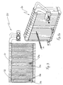
- Fig. 2 and Fig. 2a show a flat tube evaporator 10 in a view from and in a 3-D representation.
- the evaporator 10 has flat tubes 10a, between which corrugated fins 10b, which are acted upon by ambient air, are arranged.
- a cooling element 11 is arranged between two flat tubes 10a, which is connected in a heat-conducting manner with the flat tubes 10a, preferably by soldering.
- the cooling element 11 has in its (in the drawing) below lying area an inlet nozzle 11 a and an outlet nozzle 11 b for connection to the secondary or coolant circuit, not shown here (see. Secondary circuit 6 in Fig. 1 ) on.
- the flat tube evaporator 10 has a refrigerant connection flange 10c, which is connected on the one hand to a refrigerant circuit, not shown, of the motor vehicle air conditioning system and on the other hand via connection pipes 10d, 10e to the evaporator 10 or its collecting tanks.
- the evaporator 10 is traversed in the direction of the arrow L of air, which is cooled in the evaporator and fed to a passenger compartment of the motor vehicle, not shown.
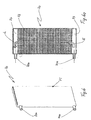
- Fig. 3 and 3a show a further embodiment of the invention in the form of a flat tube evaporator 20, in a front view and in a perspective view.
- the structure of the flat tube evaporator 20 corresponds essentially the structure of the evaporator according to Fig. 2 and 2a with the difference that here two cooling elements 21, 22 in the evaporator block, ie in each case between two adjacent flat tubes are integrated.
- the cooling elements 21, 22 correspond in their construction to the cooling element 11 according to FIG Fig. 2, 2a , ie they also have connecting pieces 21 a, 21 b and 22 a, 22 b.
- Both cooling elements 21, 22 are also connected to the secondary circuit, not shown here. Due to the multiplication of the cooling elements, the cooling capacity of the secondary circuit is increased accordingly - but at the expense of the secondary side heat exchange surface (corrugated fins) of the evaporator.
- FIG. 4 and 4a show a further embodiment of the invention in the form of an evaporator 30, in a front view and in a 3-D view.
- the evaporator 30 essentially corresponds to the prior art and is operated with an alternative refrigerant, CO2 or R744, which means a pressure-resistant design for the individual evaporator component.
- the evaporator 30 has U-shaped or serpentine-shaped flat tubes 31 (preferably multi-chamber tubes), between which corrugated ribs not shown here are arranged.
- the evaporator 30 is connected via connecting pipes 32, 33 with a not shown CO2 refrigeration cycle of a motor vehicle air conditioning system, wherein the connecting pipes 32, 33 in each case in a manifold or manifold 32 ', 33' pass.
- a collecting box 34 which in Fig. 4a is shown in an exploded view.
- This type of evaporator is also known from the prior art, for example DE 102 60 030 A1 the applicant known.
- Other designs for CO2-powered evaporators were by the DE 100 25 362 A1 known.
- a cooling element 35 is integrated approximately in the central region and disposed between two adjacent flat tubes 31, that is preferably soldered to the adjacent flat tubes.
- the cooling element 35 has in its lower region connecting pieces 35a, 35b for connection to the above-mentioned secondary circuit for cooling heat-emitting consumers.
- the Figures 5, 5a, 5b, 5c show a cooling element 60 as a single part, which corresponds to the above-mentioned cooling elements 5, 11, 21, 22, 35.
- the cooling element 60 is also made of aluminum materials and can thus be soldered to the evaporator.
- the cooling element 60 is formed as a rectangular tube 61, in which a holding frame 62 is inserted, which closes the tube 61 at the end.
- the two connecting pieces 60a, 60b are arranged on the narrow side of the rectangular tube 60.
- Fig. 5a shows the interior of the spreader tube 60, wherein between the coolant inlet 60a and the coolant outlet 60b an angularly formed partition wall 63 is arranged.
- an approximately U-shaped flow channel results between the two connecting pieces 60a, 60b, ie the cooling element 60 is flowed through in two bends.
- Flow arrows E for the entry of the coolant and U for the deflection of the coolant are in Fig. 5c shown.
- the U-shaped flow channel is filled by a turbulence plate 64, which in Fig. 5c is shown in cross section. It can be soldered to the rectangular tube 60.
- the coolant is preferably a liquid heat carrier, in particular a water-glysantin mixture.
- FIGS. 6 and 6a show a further embodiment of a cooling element 70, which can be flowed through in one flow.
- the cooling element 70 is likewise designed as a rectangular tube 71 and has in its lower region on the narrow side an inlet nozzle 70a and on the same side in its upper region an outlet nozzle 70b for connection to the secondary circuit, not shown here.
- Fig. 6a is the interior, ie the flow path of the coolant through the cooling element 70, by an inlet-side flow arrow E and an outlet-side flow arrow A.
- a turbulence plate 72 is arranged, which within the cooling element 70 free spaces 73, 74 for the distribution and collection of the coolant.
- the turbulence plate 72 By the turbulence plate 72, the heat transfer from the coolant to the rectangular tube and thus also to the refrigerant is improved. Compared with the embodiment according to Fig. 5 to 5c with double-flow results for the single-flow through a lower coolant-side pressure drop, but also a lower cooling capacity.
- the turbulence plate 72 instead of the turbulence plate 72, other heat transfer increasing means are possible, for. B. a simple réelleberippung.
- Fig. 7a, 7b, 7c, 7d show further embodiments of a cooling element. Identical features are denoted by the same reference numerals as in the preceding figures.
- Fig. 7a equals to FIG. 5b .
- Fig. 7b shows a further embodiment of a cooling element 90, which can be flowed through in one flow.
- the cooling element 90 is also formed as a rectangular tube and has in its lower region on the narrow side of an inlet port 90a and in its upper region an outlet port 90b for connection to the secondary circuit, not shown here.
- the interior that is, the flow path of the coolant through the cooling element 90, through inlet-side flow arrows E and exit-side flow arrow A.
- a turbulence plate 92 is arranged, which within the cooling element 90 free spaces the distribution and collection of Coolant leaves. By the turbulence plate 92, the heat transfer from the coolant to the rectangular tube and thus also to the refrigerant is improved.
- Inlet and outlet ports 90a, 90b are arranged on the opposite side.
- Fig. 7c corresponds to FIG. 6a .
- Fig. 7d shows a further embodiment of a cooling element 100, which can be flowed through in one flow.
- the cooling element 100 is likewise designed as a rectangular tube and has in its lower region on the narrow side an inlet nozzle 100a and in contrast to FIG. 6 and FIG. 7c on the opposite other side of the cooling element 100 in its upper region an outlet port 100b for connection to the secondary circuit, not shown here.
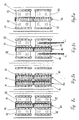
- Fig. 8a, 8b, 8c, 8d show various possibilities of arrangement or integration of cooling elements in an evaporator. Identical features are denoted by the same reference numerals as in the preceding figures.
- a cooling element 80 is disposed between adjacent flat tubes 81 of a double-row flat tube evaporator.
- the walls of the cooling element 80 thus lie directly against the flat tubes 81 and are preferably soldered to them, resulting in an excellent heat transfer.
- the heat released by the coolant in the cooling element 80 thus flows directly into the flat tubes 81, in which the refrigerant flows.
- corrugated ribs 82 are arranged, which are also soldered to the flat tubes 81.
- Fig. 8b shows a further embodiment, namely two cooling elements 80, which are each arranged between adjacent flat tubes 81.
- the two cooling elements 80 emit their heat on the one hand to the middle and on the other hand to the two outer flat tubes 81.
- Fig. 8c shows a further asymmetrical arrangement, wherein the cooling element 80 on the one hand, ie with one broad side of the flat tubes 81 and on the other hand, ie with the other broad side of corrugated ribs 82 abuts. All parts are soldered together, so that the heat from the cooling element 80 on the one hand in the flat tubes 81 and on the other hand via the corrugated fins 82 to the overhead sweeping air, represented by arrows L, is discharged.
- Fig. 8d shows a further embodiment, wherein the cooling element 80 is disposed directly between adjacent corrugated fins 82, on the other hand, with flat tubes 81 are in heat-conducting contact.
- the heat emitted by the cooling element 80 thus flows directly through heat conduction into the corrugated fins 82 and is discharged on both sides of the air flowing through the corrugated fins 82 ambient air.
Applications Claiming Priority (3)
| Application Number | Priority Date | Filing Date | Title |
|---|---|---|---|
| DE102005002060 | 2005-01-14 | ||
| DE102005049406 | 2005-10-13 | ||
| PCT/EP2006/000318 WO2006074958A2 (de) | 2005-01-14 | 2006-01-16 | Verdampfer, insbesondere für eine klimaanlage eines kraftfahrzeuges |
Publications (2)
| Publication Number | Publication Date |
|---|---|
| EP1842019A2 EP1842019A2 (de) | 2007-10-10 |
| EP1842019B1 true EP1842019B1 (de) | 2012-08-08 |
Family
ID=36128369
Family Applications (1)
| Application Number | Title | Priority Date | Filing Date |
|---|---|---|---|
| EP06706241A Expired - Fee Related EP1842019B1 (de) | 2005-01-14 | 2006-01-16 | Verdampfer, insbesondere für eine klimaanlage eines kraftfahrzeuges |
Country Status (5)
| Country | Link |
|---|---|
| US (1) | US20080184732A1 (ja) |
| EP (1) | EP1842019B1 (ja) |
| JP (1) | JP2008527306A (ja) |
| DE (1) | DE102006002194A1 (ja) |
| WO (1) | WO2006074958A2 (ja) |
Families Citing this family (12)
| Publication number | Priority date | Publication date | Assignee | Title |
|---|---|---|---|---|
| DE102006004414A1 (de) * | 2006-01-31 | 2007-08-02 | Valeo Klimasysteme Gmbh | Kühleinheit |
| DE102007032852A1 (de) * | 2007-02-22 | 2008-08-28 | Johnson Controls Automotive Electronics Gmbh | Kühlsystem für Fahrzeugkomponenten |
| EP2107328B1 (de) * | 2008-04-02 | 2012-07-11 | Behr GmbH & Co. KG | Verdampfer |
| DE102008017113A1 (de) * | 2008-04-02 | 2009-10-08 | Behr Gmbh & Co. Kg | Verdampfer |
| DE102010061768A1 (de) * | 2010-11-23 | 2012-05-24 | Behr Gmbh & Co. Kg | Vorrichtung zur Kühlung einer Wärmequelle eines Kraftfahrzeugs |
| EP2672200B1 (en) * | 2011-02-04 | 2017-10-18 | Toyota Jidosha Kabushiki Kaisha | Cooling device |
| DE102011107281A1 (de) | 2011-07-15 | 2013-01-17 | Volkswagen Ag | Chiller |
| US20140208793A1 (en) * | 2013-01-30 | 2014-07-31 | Visteon Global Technologies, Inc. | Integrated hot and cold storage systems linked to heat pump |
| DE102013211579A1 (de) * | 2013-06-19 | 2014-12-24 | Behr Gmbh & Co. Kg | Wärmetauschereinrichtung und Heizvorrichtung |
| DE102019107100A1 (de) * | 2019-03-20 | 2020-09-24 | Dr. Ing. H.C. F. Porsche Aktiengesellschaft | Kühlvorrichtung für die Kühlung eines heißen Wärmeträger-Fluids in einem Fahrzeug |
| WO2020235052A1 (ja) * | 2019-05-22 | 2020-11-26 | 三菱電機株式会社 | 熱交換器及び空気調和装置 |
| CN110230901A (zh) * | 2019-05-27 | 2019-09-13 | 广州大学 | 一种气液两相共用型的冷媒分配管及热泵系统 |
Family Cites Families (20)
| Publication number | Priority date | Publication date | Assignee | Title |
|---|---|---|---|---|
| US3315731A (en) * | 1965-05-04 | 1967-04-25 | Modine Mfg Co | Vehicle air conditioner |
| US3907032A (en) * | 1971-04-27 | 1975-09-23 | United Aircraft Prod | Tube and fin heat exchanger |
| JPS5718514A (en) * | 1980-07-08 | 1982-01-30 | Nippon Radiator Co Ltd | Air conditioner for automobile |
| JPS6192910A (ja) * | 1984-10-11 | 1986-05-10 | Diesel Kiki Co Ltd | 車両用空気調和装置 |
| US4761967A (en) * | 1984-10-11 | 1988-08-09 | Diesel Kiki Kabushiki Kaisha | Car air conditioner with heat storage tank for cooling energy |
| DE3703873A1 (de) * | 1987-02-07 | 1988-08-18 | Sueddeutsche Kuehler Behr | Kuehlkoerper, insbesondere zum kuehlen elektronischer bauelemente |
| JPH04203891A (ja) * | 1990-11-30 | 1992-07-24 | Nippondenso Co Ltd | 冷暖房兼用熱交換器 |
| DE4209188C2 (de) * | 1992-03-20 | 1994-02-03 | Kulmbacher Klimageraete | Anordnung zur Klimatisierung von Räumen, insbesondere der Fahrgastzelle von Kraftfahrzeugen |
| FR2728666A1 (fr) * | 1994-12-26 | 1996-06-28 | Valeo Thermique Habitacle | Echangeur de chaleur a trois fluides d'encombrement reduit |
| DE19646349B4 (de) * | 1996-11-09 | 2011-08-11 | Behr GmbH & Co. KG, 70469 | Verdampfer und damit ausgerüstete Fahrzeugklimaanlage |
| JPH10325649A (ja) * | 1997-05-27 | 1998-12-08 | Showa Alum Corp | 蒸発器 |
| DE19838880C5 (de) * | 1998-08-27 | 2005-05-04 | Behr Gmbh & Co. Kg | Einrichtung zum Kühlen eines Innenraumes eines Kraftfahrzeugs |
| CA2260890A1 (en) * | 1999-02-05 | 2000-08-05 | Long Manufacturing Ltd. | Self-enclosing heat exchangers |
| JP2001001753A (ja) * | 1999-06-15 | 2001-01-09 | Bosch Automotive Systems Corp | アイドルストップ車用蓄冷式空調装置 |
| FR2796337B1 (fr) * | 1999-07-12 | 2005-08-19 | Valeo Climatisation | Installation de chauffage-climatisation pour vehicule automobile |
| US6357516B1 (en) * | 2000-02-02 | 2002-03-19 | York International Corporation | Plate heat exchanger assembly with enhanced heat transfer characteristics |
| JP2003139478A (ja) * | 2001-11-01 | 2003-05-14 | Ee R C:Kk | 熱交換器 |
| DE10214965C1 (de) * | 2002-04-04 | 2003-11-20 | Webasto Thermosysteme Gmbh | Vorrichtung zum Heizen und/oder Kühlen eines Fahrzeuginnenraums |
| JP4158612B2 (ja) * | 2003-06-19 | 2008-10-01 | 株式会社デンソー | 車両用排熱回収装置 |
| DE10338824A1 (de) * | 2003-08-21 | 2005-03-24 | Behr Gmbh & Co. Kg | Klimaanlage |
-
2006
- 2006-01-16 EP EP06706241A patent/EP1842019B1/de not_active Expired - Fee Related
- 2006-01-16 DE DE102006002194A patent/DE102006002194A1/de not_active Withdrawn
- 2006-01-16 JP JP2007550768A patent/JP2008527306A/ja active Pending
- 2006-01-16 US US11/795,217 patent/US20080184732A1/en not_active Abandoned
- 2006-01-16 WO PCT/EP2006/000318 patent/WO2006074958A2/de active Application Filing
Also Published As
| Publication number | Publication date |
|---|---|
| WO2006074958A3 (de) | 2007-04-19 |
| US20080184732A1 (en) | 2008-08-07 |
| EP1842019A2 (de) | 2007-10-10 |
| DE102006002194A1 (de) | 2006-08-24 |
| WO2006074958A2 (de) | 2006-07-20 |
| JP2008527306A (ja) | 2008-07-24 |
Similar Documents
| Publication | Publication Date | Title |
|---|---|---|
| EP1842019B1 (de) | Verdampfer, insbesondere für eine klimaanlage eines kraftfahrzeuges | |
| DE60011196T2 (de) | Kombinierter Wärmetauscher mit Verdampfer, Akkumulator und Saugleitung | |
| DE112012004988T5 (de) | Wärmetauscher | |
| EP1996890B1 (de) | Wärmeübertrager mit kältespeicher | |
| EP1984196B1 (de) | Wärmeübertrager, insbesondere mit kältespeicher | |
| DE112012005002T5 (de) | Wärmetauscher | |
| DE112012005066T5 (de) | Wärmetauschsystem | |
| DE112012005008T5 (de) | Wärmetauscher | |
| DE102008048920A1 (de) | Verdampfereinheit | |
| EP1454106A1 (de) | Wärmetauscher | |
| DE102010055972A1 (de) | Evaporator mit Kältespeicherfunktion | |
| DE112015000465B4 (de) | Klimaanlagensystem für ein Fahrzeug | |
| DE10001628A1 (de) | Wärmetauscher für eine Innen/Aussenluft-Doppeldurchlasseinheit | |
| DE102018106936A1 (de) | Ladeluftkühler aus einem flüssigkeitsgekühlten Vorkühler und einem luftgekühlten Hauptkühler | |
| DE112013004141T5 (de) | Wärmetauscher zur Kältespeicherung | |
| DE102020111195A1 (de) | Kühlvorrichtung | |
| EP1703242A1 (de) | Wärmetauscher, insbesondere Kühlflüssigkeitskühler | |
| DE102015111393A1 (de) | Vorrichtung zur Wärmeübertragung | |
| DE102006004414A1 (de) | Kühleinheit | |
| DE19926052B4 (de) | Wärmetauschereinheit | |
| DE102008036614A1 (de) | Wärmetauscher | |
| EP2107328A1 (de) | Verdampfer | |
| DE102011014410A1 (de) | Vedampfereinheit | |
| DE69816260T2 (de) | Mit mehreren wärmeleitenden Platten ausgeführter Wärmetauscher | |
| DE102009018116A1 (de) | Wärmetauscher |
Legal Events
| Date | Code | Title | Description |
|---|---|---|---|
| PUAI | Public reference made under article 153(3) epc to a published international application that has entered the european phase |
Free format text: ORIGINAL CODE: 0009012 |
|
| AK | Designated contracting states |
Kind code of ref document: A2 Designated state(s): AT BE BG CH CY CZ DE DK EE ES FI FR GB GR HU IE IS IT LI LT LU LV MC NL PL PT RO SE SI SK TR |
|
| AX | Request for extension of the european patent |
Extension state: AL BA HR MK YU |
|
| 17P | Request for examination filed |
Effective date: 20071019 |
|
| RBV | Designated contracting states (corrected) |
Designated state(s): DE ES FR GB IT |
|
| 17Q | First examination report despatched |
Effective date: 20080117 |
|
| DAX | Request for extension of the european patent (deleted) | ||
| RBV | Designated contracting states (corrected) |
Designated state(s): DE ES FR GB IT |
|
| REG | Reference to a national code |
Ref country code: DE Ref legal event code: R079 Ref document number: 502006011818 Country of ref document: DE Free format text: PREVIOUS MAIN CLASS: F28D0001040000 Ipc: F28D0007000000 |
|
| GRAP | Despatch of communication of intention to grant a patent |
Free format text: ORIGINAL CODE: EPIDOSNIGR1 |
|
| RIC1 | Information provided on ipc code assigned before grant |
Ipc: F28F 3/12 20060101ALI20120126BHEP Ipc: F28D 1/053 20060101ALI20120126BHEP Ipc: F25B 39/02 20060101ALI20120126BHEP Ipc: B60H 1/00 20060101ALI20120126BHEP Ipc: F28D 7/00 20060101AFI20120126BHEP Ipc: F28D 1/04 20060101ALI20120126BHEP |
|
| GRAS | Grant fee paid |
Free format text: ORIGINAL CODE: EPIDOSNIGR3 |
|
| GRAA | (expected) grant |
Free format text: ORIGINAL CODE: 0009210 |
|
| AK | Designated contracting states |
Kind code of ref document: B1 Designated state(s): DE ES FR GB IT |
|
| REG | Reference to a national code |
Ref country code: GB Ref legal event code: FG4D Free format text: NOT ENGLISH |
|
| REG | Reference to a national code |
Ref country code: DE Ref legal event code: R096 Ref document number: 502006011818 Country of ref document: DE Effective date: 20121011 |
|
| REG | Reference to a national code |
Ref country code: DE Ref legal event code: R082 Ref document number: 502006011818 Country of ref document: DE Representative=s name: GRAUEL, ANDREAS, DIPL.-PHYS. DR. RER. NAT., DE Ref country code: DE Ref legal event code: R082 Ref document number: 502006011818 Country of ref document: DE Representative=s name: ANDREAS GRAUEL, DE |
|
| PG25 | Lapsed in a contracting state [announced via postgrant information from national office to epo] |
Ref country code: ES Free format text: LAPSE BECAUSE OF FAILURE TO SUBMIT A TRANSLATION OF THE DESCRIPTION OR TO PAY THE FEE WITHIN THE PRESCRIBED TIME-LIMIT Effective date: 20121119 |
|
| PG25 | Lapsed in a contracting state [announced via postgrant information from national office to epo] |
Ref country code: IT Free format text: LAPSE BECAUSE OF FAILURE TO SUBMIT A TRANSLATION OF THE DESCRIPTION OR TO PAY THE FEE WITHIN THE PRESCRIBED TIME-LIMIT Effective date: 20120808 |
|
| PLBE | No opposition filed within time limit |
Free format text: ORIGINAL CODE: 0009261 |
|
| STAA | Information on the status of an ep patent application or granted ep patent |
Free format text: STATUS: NO OPPOSITION FILED WITHIN TIME LIMIT |
|
| 26N | No opposition filed |
Effective date: 20130510 |
|
| REG | Reference to a national code |
Ref country code: DE Ref legal event code: R097 Ref document number: 502006011818 Country of ref document: DE Effective date: 20130510 |
|
| GBPC | Gb: european patent ceased through non-payment of renewal fee |
Effective date: 20130116 |
|
| PG25 | Lapsed in a contracting state [announced via postgrant information from national office to epo] |
Ref country code: GB Free format text: LAPSE BECAUSE OF NON-PAYMENT OF DUE FEES Effective date: 20130116 |
|
| REG | Reference to a national code |
Ref country code: DE Ref legal event code: R082 Ref document number: 502006011818 Country of ref document: DE Representative=s name: GRAUEL, ANDREAS, DIPL.-PHYS. DR. RER. NAT., DE |
|
| REG | Reference to a national code |
Ref country code: DE Ref legal event code: R081 Ref document number: 502006011818 Country of ref document: DE Owner name: MAHLE INTERNATIONAL GMBH, DE Free format text: FORMER OWNER: BEHR GMBH & CO. KG, 70469 STUTTGART, DE Effective date: 20150316 Ref country code: DE Ref legal event code: R082 Ref document number: 502006011818 Country of ref document: DE Representative=s name: GRAUEL, ANDREAS, DIPL.-PHYS. DR. RER. NAT., DE Effective date: 20150316 Ref country code: DE Ref legal event code: R081 Ref document number: 502006011818 Country of ref document: DE Owner name: MAHLE INTERNATIONAL GMBH, DE Free format text: FORMER OWNER: BEHR GMBH & CO. KG, 70469 STUTTGART, DE Effective date: 20120808 Ref country code: DE Ref legal event code: R082 Ref document number: 502006011818 Country of ref document: DE Representative=s name: GRAUEL, ANDREAS, DIPL.-PHYS. DR. RER. NAT., DE Effective date: 20121024 |
|
| REG | Reference to a national code |
Ref country code: FR Ref legal event code: PLFP Year of fee payment: 11 |
|
| REG | Reference to a national code |
Ref country code: FR Ref legal event code: PLFP Year of fee payment: 12 |
|
| REG | Reference to a national code |
Ref country code: FR Ref legal event code: PLFP Year of fee payment: 13 |
|
| PGFP | Annual fee paid to national office [announced via postgrant information from national office to epo] |
Ref country code: FR Payment date: 20190129 Year of fee payment: 14 Ref country code: DE Payment date: 20190131 Year of fee payment: 14 |
|
| REG | Reference to a national code |
Ref country code: DE Ref legal event code: R119 Ref document number: 502006011818 Country of ref document: DE |
|
| PG25 | Lapsed in a contracting state [announced via postgrant information from national office to epo] |
Ref country code: FR Free format text: LAPSE BECAUSE OF NON-PAYMENT OF DUE FEES Effective date: 20200131 Ref country code: DE Free format text: LAPSE BECAUSE OF NON-PAYMENT OF DUE FEES Effective date: 20200801 |