EP1840066B1 - Rotierendes Niederhalteelement im Falzwerk - Google Patents
Rotierendes Niederhalteelement im Falzwerk Download PDFInfo
- Publication number
- EP1840066B1 EP1840066B1 EP07006141A EP07006141A EP1840066B1 EP 1840066 B1 EP1840066 B1 EP 1840066B1 EP 07006141 A EP07006141 A EP 07006141A EP 07006141 A EP07006141 A EP 07006141A EP 1840066 B1 EP1840066 B1 EP 1840066B1
- Authority
- EP
- European Patent Office
- Prior art keywords
- hold
- folding blade
- down element
- printed product
- blade cylinder
- Prior art date
- Legal status (The legal status is an assumption and is not a legal conclusion. Google has not performed a legal analysis and makes no representation as to the accuracy of the status listed.)
- Not-in-force
Links
Images

Classifications
-
- B—PERFORMING OPERATIONS; TRANSPORTING
- B65—CONVEYING; PACKING; STORING; HANDLING THIN OR FILAMENTARY MATERIAL
- B65H—HANDLING THIN OR FILAMENTARY MATERIAL, e.g. SHEETS, WEBS, CABLES
- B65H45/00—Folding thin material
- B65H45/12—Folding articles or webs with application of pressure to define or form crease lines
- B65H45/16—Rotary folders
- B65H45/162—Rotary folders with folding jaw cylinders
- B65H45/167—Rotary folders with folding jaw cylinders having associated sheet guide means
-
- B—PERFORMING OPERATIONS; TRANSPORTING
- B41—PRINTING; LINING MACHINES; TYPEWRITERS; STAMPS
- B41F—PRINTING MACHINES OR PRESSES
- B41F13/00—Common details of rotary presses or machines
- B41F13/54—Auxiliary folding, cutting, collecting or depositing of sheets or webs
- B41F13/56—Folding or cutting
- B41F13/62—Folding-cylinders or drums
-
- B—PERFORMING OPERATIONS; TRANSPORTING
- B65—CONVEYING; PACKING; STORING; HANDLING THIN OR FILAMENTARY MATERIAL
- B65H—HANDLING THIN OR FILAMENTARY MATERIAL, e.g. SHEETS, WEBS, CABLES
- B65H9/00—Registering, e.g. orientating, articles; Devices therefor
- B65H9/08—Holding devices, e.g. finger, needle, suction, for retaining articles in registered position
-
- B—PERFORMING OPERATIONS; TRANSPORTING
- B65—CONVEYING; PACKING; STORING; HANDLING THIN OR FILAMENTARY MATERIAL
- B65H—HANDLING THIN OR FILAMENTARY MATERIAL, e.g. SHEETS, WEBS, CABLES
- B65H2301/00—Handling processes for sheets or webs
- B65H2301/40—Type of handling process
- B65H2301/44—Moving, forwarding, guiding material
- B65H2301/443—Moving, forwarding, guiding material by acting on surface of handled material
- B65H2301/4433—Moving, forwarding, guiding material by acting on surface of handled material by means holding the material
- B65H2301/44331—Moving, forwarding, guiding material by acting on surface of handled material by means holding the material at particular portion of handled material
-
- B—PERFORMING OPERATIONS; TRANSPORTING
- B65—CONVEYING; PACKING; STORING; HANDLING THIN OR FILAMENTARY MATERIAL
- B65H—HANDLING THIN OR FILAMENTARY MATERIAL, e.g. SHEETS, WEBS, CABLES
- B65H2405/00—Parts for holding the handled material
- B65H2405/50—Gripping means
- B65H2405/53—Rotary gripping arms
-
- B—PERFORMING OPERATIONS; TRANSPORTING
- B65—CONVEYING; PACKING; STORING; HANDLING THIN OR FILAMENTARY MATERIAL
- B65H—HANDLING THIN OR FILAMENTARY MATERIAL, e.g. SHEETS, WEBS, CABLES
- B65H2701/00—Handled material; Storage means
- B65H2701/10—Handled articles or webs
- B65H2701/13—Parts concerned of the handled material
- B65H2701/131—Edges
- B65H2701/1311—Edges leading edge
Definitions
- the invention relates to a folding apparatus of a rotary printing press and the transfer of the printed product from a folding blade cylinder to a jaw cylinder.
- a folding apparatus having a first cylinder and a second cylinder and a guide device for guiding at least one trailing end of a product, wherein the product is transferred from the first cylinder to the second cylinder.
- the guide device is designed either as a flexible plate / strip or as a rotating cam.
- the folding blade cylinder has holding devices to hold the printed product on the surface of the folding blade.
- the holding device can be designed, for example, in the form of a puncture device. Due to the arrangement of jaw cylinder and folding blade to each other, it is necessary for the decrease of the printed product by the jaw cylinder that the puncture in the forward direction, the printed product releases. By releasing the printed product, the leading end of the printed product is no longer guided defined so that it can cause buckling and cracks on the printed product.
- a folding apparatus which has a folding blade cylinder and a jaw cylinder.
- the folding blade cylinder has holding elements, such as e.g. a puncture or puncture device, so that the folding blade is also called NOTEurzylinder.
- the folding blade cylinder can take on other functions, such as e.g. Collecting the printed products, so that the folding blade cylinder is also called collecting cylinder.
- Folding blade cylinder and jaw cylinder come in a transfer section next. In this transfer section, the printed product is folded transversely by the folding blade pushes the printed product in the jaw.
- the so-called gusset which lies in the region downstream of the transfer section in the direction of rotation, a rotating hold-down element is provided.
- the rotating hold-down element which may for example be in the form of a cam, serves to press the leading edge of the printed product against the folding blade cylinder as soon as the puncturing device has released the printed product.
- the shape of the hold-down element is not limited to the cam shape. Rather, any shape is conceivable as long as the function of holding down the printed product is fulfilled only at the time of release of the printed product by the puncturing and at the time of transfer to the jaw cylinder, the path between folding blade and jaw cylinder, which takes the printed product, released by the rotating hold-down is.
- the hold-down element itself or the bearing of the hold-down element must be such that the distance between hold-down element and folding blade varies during rotation of the hold-down element. That is, the shape of the hold-down element and the speeds of hold-down element and Folding blade cylinders must be designed such that the space between the folding blade cylinder and hold-down element per printed product is at least once minimal.
- the at least one hold-down element is used in combination with guide tongues.
- the Leitzungen are a rigid component between folding blade and jaw cylinder, which provides a guide for the printed product, which is removed by the Falzklappenzylinder of the folding blade cylinder.
- At least two Leitzungen are arranged between folding blade cylinder and jaw cylinder, so that the entire product width is performed. Furthermore, it should be provided to rotate at least two cam disks of the hold-down element at or between the guide tongues.
- the hold-down element does not interfere with the guiding function of the guide tongue. That is, if a printed product is guided on a guide surface of the at least one guide tab, the rotating hold-down element must not damage the product.
- the hold-down element is equipped with a single drive which can be controlled or regulated in its rotational speed.
- a single drive which can be controlled or regulated in its rotational speed.
- the hold-down element can be controlled by the individual drive adapt to the delayed movement of the printed product, so that it does not come to the relative movement between the printed product and hold-down element.
- the support by means of an air flow increases the functional range of the hold-down element.
- the air flow can be accomplished on the one hand by a corresponding shaping of the hold-down element, but it can also by providing a corresponding compressed air device, e.g. in the area between the cylinders.
- the compressed air device can be realized, for example, in the form of a compressed air beam running transversely along the guide tongues. Further, the compressed air beam can be mounted on the hold-down element, so that the flow of compressed air is predetermined by the movement of the hold-down elements.
- the compressed air device can be controlled so that compressed air always flows out when the leading end of the printed product has been released by the puncturing device.
- the distance between hold-down element and folding blade cylinder is adjustable, so that the distance can be adapted to the printed product thickness.
- the in FIG. 1 The folder shown has a folding blade cylinder 2 and a jaw cylinder 3.
- the folding blade 2 is equipped with evenly distributed on the circumference folding blades 13.
- the jaws 4 interact with the folding blades 13 such that a folding blade 13 presses the printed product 5 in the jaw 4 and the printed product 5 is then held by the jaw 4.
- the folding blade cylinder 2 has a puncture 1, which holds the printed product 5 at through the puncture 1 resulting holes.
- the puncture 1 must be retracted at the latest, i. the printed product 5 must be released from the puncture 1. Due to the rotational speed of the folding blade 2, the printed product 5 then lifts off from the folding blade 2 and is detected by the incoming at this time cam 6.
- the cam 6 is adapted in its speed to the speed of the printed product 5, so that the freshly printed substrate is not damaged, i. so that it does not come to a so-called greasing of the color on the printed product.
- the printed product 5 is delayed to zero speed and then conveyed along the Leitzept 8 in the direction of the jaw cylinder 3. At the time of the guide of the printed product 5 along the guide surface 9 of the Leitzunge 8 of the protruding part of the cam 6 is behind the Leitzunge 8, so that the path of the printed product 5 along the guide surface 9 is not disturbed.
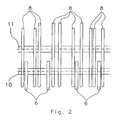
- FIG. 2 shows a plan view of the inventive arrangement.
- the shaft 10 for running as cams 6 hold-down elements and the mounting rod 11 for attachment of the lead tongues 8 are immediately adjacent arranged.
- the cam 6 is respectively disposed between the guide tongues 8, but it is also possible to attach the cam 6 outside the outermost lead tongues 8.
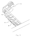
- FIG. 3 shows a perspective view of the shaft 10 for the cams 6 and the mounting rod 11 for the Leitzungen 8.
- the drive 12 of the shaft 10 for the cam 6 shown. It should be noted in this context that this can be a controllable single drive. Furthermore, however, the use of a drive is conceivable, which also drives other components of the folder.
Landscapes
- Engineering & Computer Science (AREA)
- Mechanical Engineering (AREA)
- Folding Of Thin Sheet-Like Materials, Special Discharging Devices, And Others (AREA)
Description
- Die Erfindung betrifft einen Falzapparat einer Rotationsdruckmaschine und die Überführung des Druckproduktes von einem Falzmesserzylinder zu einem Falzklappenzylinder.
- Aus der
EP 1 207 128 A2 ist ein Falzapparat mit einem ersten Zylinder und einem zweiten Zylinder sowie einer Führungseinrichtung zum Führen wenigstens eines nachlaufenden Endes eines Produktes bekannt, wobei das Produkt von dem ersten Zylinder an den zweiten Zylinder übergeben wird. Die Führungseinrichtung ist entweder als flexible Platte / Streifen oder als rotierende Nocke ausführt. - Bei Falzapparaten ist es bekannt, Produkte an der Mantelfläche eines Falzmesserzylinders zu halten und zu einem Falzklappenzylinder zu überführen. Dort werden die Druckprodukte von einem Falzmesser zur Querfalzung in eine Falzklappe des Falzklappenzylinders übergeben. Der Falzmesserzylinder weist Haltevorrichtungen auf, um das Druckprodukt an der Oberfläche des Falzmesserzylinders zu halten. Die Haltevorrichtung kann beispielsweise in Form einer Punktureinrichtung ausgebildet sein. Aufgrund der Anordnung von Falzklappenzylinder und Falzmesserzylinder zueinander, ist es bei Abnahme des Druckprodukts durch den Falzklappenzylinder notwendig, dass die Punktur in Vorlaufrichtung das Druckprodukt frei gibt. Durch das Freigeben des Druckproduktes wird das vorlaufende Ende des Druckprodukts nicht mehr definiert geführt, so dass es zu Knicken und Rissen am Druckprodukt kommen kann.
- Ausgehend von dieser Problematik ist es Aufgabe der vorliegenden Erfindung, einen Falzapparat bereit zu stellen, der es ermöglicht, ein Druckprodukt ohne Beschädigungen vom Falzmesserzylinder auf den Falzklappenzylinder zu übergeben.
- Diese Aufgabe wird durch den unabhängigen Anspruch 1 der vorliegenden Erfindung gelöst. Die abhängigen Ansprüche sind vorteilhafte Ausgestaltungen der Erfindung.
- Erfindungsgemäß ist ein Falzapparat vorgesehen, der einen Falzmesserzylinder und einen Falzklappenzylinder aufweist. Der Falzmesserzylinder weist Halteelemente auf, wie z.B. eine Punktur bzw. Punktureinrichtung, so dass der Falzmesserzylinder auch Punkturzylinder genannt wird. Ferner kann der Falzmesserzylinder weitere Funktionen übernehmen, wie z.B. das Sammeln der Druckprodukte, so dass der Falzmesserzylinder auch Sammelzylinder genannt wird. Falzmesserzylinder und Falzklappenzylinder kommen sich in einem Übergabeabschnitt am Nächsten. In diesem Übergabeabschnitt wird das Druckprodukt quer gefalzt, indem das Falzmesser das Druckprodukt in die Falzklappe schiebt. In dem Bereich zwischen Falzmesserzylinder und Falzklappenzylinder, dem sog. Zwickel, der in dem in Umlaufrichtung dem Übergabeabschnitt nachgelagertem Bereich liegt, ist ein rotierendes Niederhalteelement vorgesehen.
- Das rotierende Niederhalteelement, das beispielsweise in Form einer Nocke ausgebildet sein kann, dient dazu, die vorlaufende Kante des Druckproduktes an den Falzmesserzylinder zu drücken, sobald die Punktureinrichtung das Druckprodukt freigegeben hat.
- Die Form des Niederhalteelements ist allerdings nicht auf die Nockenform eingeschränkt. Vielmehr ist jede Form denkbar, solange nur zum Zeitpunkt der Freigabe des Druckproduktes durch die Punktureinrichtung die Funktion des Niederhaltens des Druckproduktes erfüllt wird und zum Zeitpunkt der Übergabe an den Falzklappenzylinder der Weg zwischen Falzmesserzylinder und Falzklappenzylinder, den das Druckprodukt nimmt, durch das rotierende Niederhalteelement freigegeben ist.
- Erfindungsgemäß muss, gemäß einer vorteilhaften Ausgestaltung der Erfindung, das Niederhalteelement selbst oder die Lagerung des Niederhalteelements so beschaffen sein, dass der Abstand zwischen Niederhalteelement und Falzmesserzylinder während einer Drehung des Niederhalteelements variiert. Das heißt, die Form des Niederhalteelements und die Drehzahlen von Niederhalteelement und Falzmesserzylinder müssen derart ausgelegt sein, dass der Raum zwischen Falzmesserzylinder und Niederhalteelement pro Druckprodukt zumindest einmal minimal wird.
- Erfindungsgemäß wird das mindestens eine Niederhalteelement in Kombination mit Leitzungen verwendet. Die Leitzungen sind ein starres Bauteil zwischen Falzmesserzylinder und Falzklappenzylinder, das eine Führung für das Druckprodukt bietet, das durch den Falzklappenzylinder von dem Falzmesserzylinder abgenommen wird. Mindestens zwei Leitzungen sind zwischen Falzmesserzylinder und Falzklappenzylinder angeordnet, so dass die ganze Produktbreite geführt wird. Ferner ist es vorzusehen, mindestens zwei Kurvenscheiben des Niederhalteelements an oder zwischen den Leitzungen rotieren zu lassen. Nicht der Erfindung entsprechend ist es auch möglich, die Führung des Druckproduktes von Falzmesserzylinder zu Falzklappenzylinder mittels entsprechenden beweglichen Bauteilen oder sogar durch entsprechend angepasste Niederhalteelemente zu verwirklichen. Beim Zusammenspiel von Leitzunge und Niederhalteelement muss darauf geachtet werden, dass das Niederhalteelement nicht die Führungsfunktion der Leitzunge beeinträchtigt. Das heißt, wenn auf einer Führungsfläche der mindestens einen Leitzunge ein Druckprodukt geführt wird, darf das rotierende Niederhalteelement das Produkt nicht beschädigen.
- Erfindungsgemäß ist vorgesehen, das Niederhalteelement mit einem Einzelantrieb auszustatten, der in seiner Drehgeschwindigkeit steuer- bzw. regelbar ist. Durch die Steuerung der Drehgeschwindigkeit des Niederhalteelements wird es möglich, das Niederhalteelement in seiner Geschwindigkeit an die Geschwindigkeit des Druckproduktes anzupassen. Bei der Übergabe des Druckproduktes vom Falzmesserzylinder auf den Falzklappenzylinder wird das Druckprodukt bis zum Stillstand verzögert und dann bei der Abnahme des Druckproduktes vom Falzmesserzylinder in eine andere Bewegungsrichtung beschleunigt. Das Niederhalteelement kann sich durch den gesteuerten Einzelantrieb an die verzögerte Bewegung des Druckproduktes anpassen, so dass es nicht zur Relativbewegung zwischen Druckprodukt und Niederhalteelement kommt.
- Gemäß einer weiteren Ausgestaltung der Erfindung ist vorgesehen, die Funktion des Niederdrückens des Druckproduktes auf den Falzmesserzylinder durch eine geeignete Luftströmung zu unterstützen. Durch die Unterstützung mittels einer Luftströmung wird die Funktionsreichweite des Niederhalteelements vergrößert. Die Luftströmung kann einerseits durch eine entsprechende Formgebung des Niederhalterelements bewerkstelligt werden, sie kann aber auch durch das Bereitstellen einer entsprechenden Drucklufteinrichtung z.B. im Bereich zwischen den Zylindern erfolgen. Die Drucklufteinrichtung kann beispielsweise in Form eines in Querrichtung entlang der Leitzungen verlaufenden Druckluftbalkens verwirklicht werden. Ferner kann der Druckluftbalken auf dem Niederhalteelement angebracht sein, so dass die Strömung der Druckluft durch die Bewegung der Niederhalteelemente vorgegeben wird. Darüber hinaus kann die Drucklufteinrichtung gesteuert sein, so dass Druckluft immer dann ausströmt, wenn das vorlaufende Druckproduktende durch die Punktureinrichtung freigegeben wurde.
- Gemäß einer weiteren Ausgestaltung der Erfindung ist der Abstand zwischen Niederhalteelement und Falzmesserzylinder einstellbar, so dass der Abstand an die Druckproduktdicke angepasst werden kann.
- Die vorliegende Erfindung wird anhand von Zeichnungen einer Ausführungsform der Erfindung näher erläutert. Es zeigt:
- Figur 1
- eine Seitenansicht von Falzmesserzylinder und Falzklappenzylinder mit im Zwickel angeordneter rotierender Niederhalteeinheit;
- Figur 2
- eine Draufsicht auf die Leitzungen und Kurvenscheiben des Niederhalteelements zwischen Falzmesserzylinder und Falzklappenzylinder und
- Figur 3
- eine perspektivische Ansicht der Leitzungen und der rotierenden Kurvenscheiben des Niederhalteelements.
- Der in
Figur 1 gezeigte Falzapparat weist einen Falzmesserzylinder 2 und einen Falzklappenzylinder 3 auf. Der Falzmesserzylinder 2 ist mit gleichmäßig am Umfang verteilten Falzmessern 13 bestückt. Die Falzklappen 4 wirken mit den Falzmessern 13 derart zusammen, dass ein Falzmesser 13 das Druckprodukt 5 in die Falzklappe 4 drückt und das Druckprodukt 5 daraufhin von der Falzklappe 4 gehalten wird. Ferner weist der Falzmesserzylinder 2 eine Punktur 1 auf, die das Druckprodukt 5 an durch die Punktur 1 entstehenden Löchern hält. - Sobald durch die Rotation von Falzmesserzylinder 2 und Falzklappenzylinder 3 das Druckprodukt 5 zwischen Falzklappe 4 und Punktur 1 unter Spannung gerät, muss die Punktur 1 spätestens zurückgefahren werde, d.h. das Druckprodukt 5 muss von der Punktur 1 freigegeben werden. Bedingt durch die Rotationsgeschwindigkeit des Falzmesserzylinders 2 hebt das Druckprodukt 5 daraufhin vom Falzmesserzylinder 2 ab und wird von der zu diesem Zeitpunkt eintreffenden Kurvenscheibe 6 erfasst. Die Kurvenscheibe 6 ist in ihrer Geschwindigkeit an die Geschwindigkeit des Druckproduktes 5 angepasst, so dass der frisch bedruckte Bedruckstoff nicht beschädigt wird, d.h. so dass es nicht zu einem so genannten Abschmieren der Farbe auf dem Druckprodukt kommt. Durch die Übernahme des Druckproduktes von dem Falzklappenzylinder 3 wird das Druckprodukt 5 auf die Geschwindigkeit Null verzögert und dann entlang der Leitzungen 8 in Richtung des Falzklappenzylinders 3 gefördert. Zum Zeitpunkt der Führung des Druckproduktes 5 entlang der Führungsfläche 9 der Leitzunge 8 ist der hervorstehende Teil der Kurvenscheibe 6 hinter der Leitzunge 8, so dass der Weg des Druckproduktes 5 entlang der Führungsfläche 9 nicht gestört wird.
-
Figur 2 zeigt eine Draufsicht auf die erfindungsgemäße Anordnung. Die Welle 10 für die als Kurvenscheiben 6 ausgeführten Niederhalteelemente und die Befestigungsstange 11 zur Befestigung der Leitzungen 8 sind unmittelbar nebeneinander angeordnet. In dieser Ausführungsform wird die Kurvenscheibe 6 jeweils zwischen den Leitzungen 8 angeordnet, jedoch ist es auch möglich, die Kurvenscheiben 6 außen neben die äußersten Leitzungen 8 anzubringen. -
Figur 3 zeigt eine perspektivische Ansicht der Welle 10 für die Kurvenscheiben 6 und der Befestigungsstange 11 für die Leitzungen 8. Darüber hinaus ist inFigur 3 der Antrieb 12 der Welle 10 für die Kurvenscheiben 6 gezeigt. Es wird in diesem Zusammenhang darauf hingewiesen, dass es sich hierbei um einen steuerbaren Einzelantrieb handeln kann. Ferner ist aber auch die Verwendung eines Antriebs denkbar, der auch noch weitere Bauelemente des Falzapparats antreibt. -
- 1
- Halteelement, Punktur
- 2
- Falzmesserzylinder
- 3
- Falzklappenzylinder
- 4
- Falzklappe
- 5
- Druckprodukt
- 6
- Niederhalteelement
- 7
- Übergabeabschnitt
- 8
- Leitzunge
- 9
- Führungsfläche
- 10
- Welle für die Kurvenscheiben
- 11
- Befestigungsstange für Leitzungen
- 12
- Antrieb
- 13
- Falzmesser
Claims (12)
- Falzapparat mit einem mindestens ein Halteelement (1) aufweisenden Falzmesserzylinder (2) und einem Falzklappenzylinder (3), der über eine Falzklappe (4) ein Druckprodukt (5) in einem Übergabeabschnitt (7) von dem Falzmesserzylinder (2) abnimmt, wobei zwischen Falzmesserzylinder (2) und Falzklappenzylinder (3) mindestens zwei als starres Bauteil ausgeführte Leitzungen (8) vorgesehen sind, welche eine Führung für das Druckprodukt bieten, wobei ein rotierendes Niederhalteelement (6), welches in Rotationsrichtung des Falzmesserzylinders (2) nach dem Übergabeabschnitt (7) angeordnet ist, zum Niederdrücken einer auf dem Falzmesserzylinder (2) vorlaufenden Druckproduktkante in Richtung des Falzmesserzylinders (2) vorgesehen ist, wobei mindestens zwei Kurvenscheiben des Niederhalteelements (6) an oder zwischen zwei Leitzungen (8) rotieren und wobei das Niederhalteelement (6) mit einem Einzelantrieb ausgestattet ist, welcher eine Steuerung oder Regelung aufweist, um die Drehgeschwindigkeit des Niederhalteelements (6) anzupassen und der Einzelantrieb derart gesteuert oder geregelt wird, dass die Drehgeschwindigkeit des Niederhalteelements während einer Umdrehung variierbar ist.
- Falzapparat nach Anspruch 1, dadurch gekennzeichnet, dass das Niederhalteelement (6) derart geformt und/oder gelagert ist, dass ein Abstand zwischen dem Niederhalteelement (6) und dem Falzmesserzylinder (2) während der Drehung des Niederhalteelements (6) variiert, sodass der Raum zwischen. Falzmesserzylinder (2) und Niederhalteelement (6) pro Druckprodukt (5) zumindest einmal minimal wird.
- Falzapparat nach Anspruch 2, dadurch gekennzeichnet, dass Drehgeschwindigkeit und Form des Niederhalteelements (6) derart auf die Leitzunge (8) und die Geschwindigkeit des Druckproduktes (5) abgestimmt sind, dass die Funktion einer Führungsfläche (9) der Leitzunge (8) nicht durch das Niederhalteelements (6) beeinträchtigt wird, indem sich der hervorstehende Teil der Kurvenscheibe (6) zum Zeitpunkt der Führung des Druckproduktes (5) entlang der Leitzunge (8) hinter der Leitzunge (8) befindet.
- Falzapparat nach einem der vorherigen Ansprüche, dadurch gekennzeichnet, dass Form und Drehzahl des Niederhalteelements (6) auf die Drehzahl des Falzmesserzylinders (2) abgestimmt sind, sodass der Raum zwischen Falzmesserzylinder (2) und Niederhalteelement (6) pro Druckprodukt (5) zumindest einmal minimal wird.
- Falzapparat nach einem der Ansprüche 1 bis 4, dadurch gekennzeichnet, dass das Niederhalteelement (6) derart geformt ist, dass durch die Drehung des Niederhalteelements (6) eine Luftströmung zum Niederdrücken des Druckprodukts (5) in Richtung des Falzmesserzylinders (2) erzeugt wird.
- Falzapparat nach einem der vorherigen Ansprüche, dadurch gekennzeichnet, dass eine Drucklufteinrichtung vorgesehen ist, um eine Luftströmung zum Niederdrücken des Druckprodukts (5) in Richtung des Falzmesserzylinders (2) zu erzeugen.
- Falzapparat nach Anspruch 6, dadurch gekennzeichnet, dass die Drucklufteinrichtung an dem Niederhalteelement (6) vorgesehen ist, um eine Luftströmung zum Niederdrücken des Druckprodukts in Richtung des Falzmesserzylinders (2) zu erzeugen.
- Falzapparat nach Anspruch 6 oder 7, dadurch gekennzeichnet, dass eine Beaufschlagung der Drucklufteinrichtung mit Druckluft in Abhängigkeit von der Winkellage des Niederhalteelements (6) und/oder Lage des Druckproduktes (5) und/oder Winkellage des Falzmesserzylinders (2) gesteuert oder geregelt ist.
- Falzapparat nach Anspruch 1, dadurch gekennzeichnet, dass die Kurvenscheibe nockenförmig ausgebildet ist.
- Falzapparat nach einem der Ansprüche 1 bis 8, dadurch gekennzeichnet, dass das rotierende Niederhalteelement (6) mindestens ein rotierendes Federelement aufweist.
- Falzapparat nach einem der vorherigen Ansprüche, dadurch gekennzeichnet, dass der Falzmesserzylinder (2) ebenso ein Punktur- und/oder Sammelzylinder ist.
- Falzapparat nach einem der vorherigen Ansprüche, dadurch gekennzeichnet, dass der Abstand zwischen dem Niederhalteelement (6) und dem Falzmesserzylinder (2) abhängig von der Dicke des Druckprodukts (5) einstellbar ist.
Applications Claiming Priority (1)
| Application Number | Priority Date | Filing Date | Title |
|---|---|---|---|
| DE102006014219A DE102006014219A1 (de) | 2006-03-28 | 2006-03-28 | Exemplarführung im Falzwerk |
Publications (3)
| Publication Number | Publication Date |
|---|---|
| EP1840066A2 EP1840066A2 (de) | 2007-10-03 |
| EP1840066A3 EP1840066A3 (de) | 2008-06-25 |
| EP1840066B1 true EP1840066B1 (de) | 2011-10-26 |
Family
ID=38109658
Family Applications (1)
| Application Number | Title | Priority Date | Filing Date |
|---|---|---|---|
| EP07006141A Not-in-force EP1840066B1 (de) | 2006-03-28 | 2007-03-26 | Rotierendes Niederhalteelement im Falzwerk |
Country Status (3)
| Country | Link |
|---|---|
| EP (1) | EP1840066B1 (de) |
| AT (1) | ATE530484T1 (de) |
| DE (1) | DE102006014219A1 (de) |
Families Citing this family (1)
| Publication number | Priority date | Publication date | Assignee | Title |
|---|---|---|---|---|
| US9878871B2 (en) | 2012-12-31 | 2018-01-30 | Goss International Americas, Inc. | Dynamic guide for a paper folding machine |
Family Cites Families (6)
| Publication number | Priority date | Publication date | Assignee | Title |
|---|---|---|---|---|
| US4494949A (en) * | 1983-01-10 | 1985-01-22 | The Lehigh Press, Inc. | Sheet folding apparatus and method |
| DE3705195A1 (de) * | 1987-02-19 | 1988-09-01 | Frankenthal Ag Albert | Leiteinrichtung |
| DE8809285U1 (de) * | 1988-07-20 | 1988-09-01 | Heidelberger Druckmaschinen Ag, 6900 Heidelberg, De | |
| DE4217814C2 (de) * | 1992-05-29 | 1995-07-13 | Heidelberger Druckmasch Ag | Einrichtung zur Unterstützung des kontrollierten Exemplartransportes im Falzapparat von Rotationsdruckmaschinen |
| US6605027B1 (en) * | 2000-11-16 | 2003-08-12 | Heidelberger Druckmaschinen Ag | Fold-off guide for a folder in a paper-processing machine |
| JP3415115B2 (ja) * | 2000-11-27 | 2003-06-09 | 株式会社東京機械製作所 | 折畳装置のガイド装置 |
-
2006
- 2006-03-28 DE DE102006014219A patent/DE102006014219A1/de not_active Withdrawn
-
2007
- 2007-03-26 EP EP07006141A patent/EP1840066B1/de not_active Not-in-force
- 2007-03-26 AT AT07006141T patent/ATE530484T1/de active
Also Published As
| Publication number | Publication date |
|---|---|
| EP1840066A2 (de) | 2007-10-03 |
| DE102006014219A1 (de) | 2007-10-04 |
| EP1840066A3 (de) | 2008-06-25 |
| ATE530484T1 (de) | 2011-11-15 |
Similar Documents
| Publication | Publication Date | Title |
|---|---|---|
| CH617905A5 (de) | ||
| EP1882661A2 (de) | Bogenbremsensystem zum Bremsen von Druckbogen | |
| EP0303053B1 (de) | Vorrichtung zur Übergabe von Bogen | |
| DE4340858C2 (de) | Zylinder | |
| EP1541510B1 (de) | Vorrichtung zum Fördern eines Bogens durch eine drucktechnische Maschine | |
| DE2407752A1 (de) | Verfahren und vorrichtung zum auslegen von bogen | |
| DE102007053490A1 (de) | Sammelhefter mit variabler Kettenteilung | |
| EP2100837B1 (de) | Bogenanleger zum Beschicken einer Transportvorrichtung mit Druckbogen | |
| DE102006018769B3 (de) | Vorrichtung zum Transport bogenförmiger flacher Gegenstände | |
| EP1840066B1 (de) | Rotierendes Niederhalteelement im Falzwerk | |
| DE3114581C2 (de) | Fördervorrichtung für eine Bogen-Rotationsdruckmaschine | |
| DE102005008000B4 (de) | Vorrichtung zum Fördern von Produkten | |
| DE19614491C2 (de) | Bogenbremse im Ausleger einer Druckmaschine | |
| DE10043991A1 (de) | Vorrichtung zum Drehen flacher Gegenstände, insbesondere von Faltschachtelzuschnitten | |
| WO1994013565A1 (de) | Vorrichtung zum überführen von einzelnen druckprodukten eines schuppenstromes | |
| EP1700803A1 (de) | Vorrichtung zum Oeffnen und Ablegen eines gefalzten Bogens | |
| EP1988040B1 (de) | Bogenanleger zum Beschicken einer Transportvorrichtung mit gefalzten Druckbogen | |
| DE19847399B4 (de) | Greiferwagen in Auslegern von Bogendruckmaschinen | |
| DE602648C (de) | Vorrichtung zum Entnehmen des jeweils untersten Blattes von einem Blaetterstapel | |
| DE102009001190B4 (de) | Bogenverarbeitende Maschine mit einem Anlegetisch | |
| DE19602248A1 (de) | Längsfalzvorrichtung | |
| DE19947810B4 (de) | Saugwalze in Bogenauslegern von Druckmaschinen | |
| EP1285871B1 (de) | Ausleger zur Entnahme von gefalzten Druckprodukten | |
| CH695767A5 (de) | Bedruckstoff verarbeitende Maschine mit einer Transportbandeinrichtung. | |
| EP1972587A1 (de) | Einrichtung zum Sammeln von Druckprodukten auf einem Sammelzylinder |
Legal Events
| Date | Code | Title | Description |
|---|---|---|---|
| PUAI | Public reference made under article 153(3) epc to a published international application that has entered the european phase |
Free format text: ORIGINAL CODE: 0009012 |
|
| AK | Designated contracting states |
Kind code of ref document: A2 Designated state(s): AT BE BG CH CY CZ DE DK EE ES FI FR GB GR HU IE IS IT LI LT LU LV MC MT NL PL PT RO SE SI SK TR |
|
| AX | Request for extension of the european patent |
Extension state: AL BA HR MK YU |
|
| PUAL | Search report despatched |
Free format text: ORIGINAL CODE: 0009013 |
|
| AK | Designated contracting states |
Kind code of ref document: A3 Designated state(s): AT BE BG CH CY CZ DE DK EE ES FI FR GB GR HU IE IS IT LI LT LU LV MC MT NL PL PT RO SE SI SK TR |
|
| AX | Request for extension of the european patent |
Extension state: AL BA HR MK RS |
|
| RAP1 | Party data changed (applicant data changed or rights of an application transferred) |
Owner name: MANROLAND AG |
|
| 17P | Request for examination filed |
Effective date: 20081220 |
|
| AKX | Designation fees paid |
Designated state(s): AT BE BG CH CY CZ DE DK EE ES FI FR GB GR HU IE IS IT LI LT LU LV MC MT NL PL PT RO SE SI SK TR |
|
| 17Q | First examination report despatched |
Effective date: 20090211 |
|
| GRAP | Despatch of communication of intention to grant a patent |
Free format text: ORIGINAL CODE: EPIDOSNIGR1 |
|
| RIN1 | Information on inventor provided before grant (corrected) |
Inventor name: BATKE, MANFRED Inventor name: SATTLER, WOLFGANG Inventor name: RUMESZ, FRANZ Inventor name: JAEGER, WOLFGANG |
|
| GRAS | Grant fee paid |
Free format text: ORIGINAL CODE: EPIDOSNIGR3 |
|
| GRAA | (expected) grant |
Free format text: ORIGINAL CODE: 0009210 |
|
| AK | Designated contracting states |
Kind code of ref document: B1 Designated state(s): AT BE BG CH CY CZ DE DK EE ES FI FR GB GR HU IE IS IT LI LT LU LV MC MT NL PL PT RO SE SI SK TR |
|
| REG | Reference to a national code |
Ref country code: GB Ref legal event code: FG4D Free format text: NOT ENGLISH |
|
| REG | Reference to a national code |
Ref country code: CH Ref legal event code: EP |
|
| REG | Reference to a national code |
Ref country code: IE Ref legal event code: FG4D |
|
| REG | Reference to a national code |
Ref country code: DE Ref legal event code: R096 Ref document number: 502007008488 Country of ref document: DE Effective date: 20111229 |
|
| REG | Reference to a national code |
Ref country code: NL Ref legal event code: VDEP Effective date: 20111026 |
|
| LTIE | Lt: invalidation of european patent or patent extension |
Effective date: 20111026 |
|
| PG25 | Lapsed in a contracting state [announced via postgrant information from national office to epo] |
Ref country code: LT Free format text: LAPSE BECAUSE OF FAILURE TO SUBMIT A TRANSLATION OF THE DESCRIPTION OR TO PAY THE FEE WITHIN THE PRESCRIBED TIME-LIMIT Effective date: 20111026 Ref country code: IS Free format text: LAPSE BECAUSE OF FAILURE TO SUBMIT A TRANSLATION OF THE DESCRIPTION OR TO PAY THE FEE WITHIN THE PRESCRIBED TIME-LIMIT Effective date: 20120226 |
|
| PG25 | Lapsed in a contracting state [announced via postgrant information from national office to epo] |
Ref country code: SI Free format text: LAPSE BECAUSE OF FAILURE TO SUBMIT A TRANSLATION OF THE DESCRIPTION OR TO PAY THE FEE WITHIN THE PRESCRIBED TIME-LIMIT Effective date: 20111026 Ref country code: PL Free format text: LAPSE BECAUSE OF FAILURE TO SUBMIT A TRANSLATION OF THE DESCRIPTION OR TO PAY THE FEE WITHIN THE PRESCRIBED TIME-LIMIT Effective date: 20111026 Ref country code: PT Free format text: LAPSE BECAUSE OF FAILURE TO SUBMIT A TRANSLATION OF THE DESCRIPTION OR TO PAY THE FEE WITHIN THE PRESCRIBED TIME-LIMIT Effective date: 20120227 Ref country code: GR Free format text: LAPSE BECAUSE OF FAILURE TO SUBMIT A TRANSLATION OF THE DESCRIPTION OR TO PAY THE FEE WITHIN THE PRESCRIBED TIME-LIMIT Effective date: 20120127 Ref country code: NL Free format text: LAPSE BECAUSE OF FAILURE TO SUBMIT A TRANSLATION OF THE DESCRIPTION OR TO PAY THE FEE WITHIN THE PRESCRIBED TIME-LIMIT Effective date: 20111026 Ref country code: SE Free format text: LAPSE BECAUSE OF FAILURE TO SUBMIT A TRANSLATION OF THE DESCRIPTION OR TO PAY THE FEE WITHIN THE PRESCRIBED TIME-LIMIT Effective date: 20111026 Ref country code: LV Free format text: LAPSE BECAUSE OF FAILURE TO SUBMIT A TRANSLATION OF THE DESCRIPTION OR TO PAY THE FEE WITHIN THE PRESCRIBED TIME-LIMIT Effective date: 20111026 |
|
| REG | Reference to a national code |
Ref country code: IE Ref legal event code: FD4D |
|
| PG25 | Lapsed in a contracting state [announced via postgrant information from national office to epo] |
Ref country code: CY Free format text: LAPSE BECAUSE OF FAILURE TO SUBMIT A TRANSLATION OF THE DESCRIPTION OR TO PAY THE FEE WITHIN THE PRESCRIBED TIME-LIMIT Effective date: 20111026 |
|
| PG25 | Lapsed in a contracting state [announced via postgrant information from national office to epo] |
Ref country code: EE Free format text: LAPSE BECAUSE OF FAILURE TO SUBMIT A TRANSLATION OF THE DESCRIPTION OR TO PAY THE FEE WITHIN THE PRESCRIBED TIME-LIMIT Effective date: 20111026 Ref country code: BG Free format text: LAPSE BECAUSE OF FAILURE TO SUBMIT A TRANSLATION OF THE DESCRIPTION OR TO PAY THE FEE WITHIN THE PRESCRIBED TIME-LIMIT Effective date: 20120126 Ref country code: IE Free format text: LAPSE BECAUSE OF FAILURE TO SUBMIT A TRANSLATION OF THE DESCRIPTION OR TO PAY THE FEE WITHIN THE PRESCRIBED TIME-LIMIT Effective date: 20111026 Ref country code: SK Free format text: LAPSE BECAUSE OF FAILURE TO SUBMIT A TRANSLATION OF THE DESCRIPTION OR TO PAY THE FEE WITHIN THE PRESCRIBED TIME-LIMIT Effective date: 20111026 Ref country code: CZ Free format text: LAPSE BECAUSE OF FAILURE TO SUBMIT A TRANSLATION OF THE DESCRIPTION OR TO PAY THE FEE WITHIN THE PRESCRIBED TIME-LIMIT Effective date: 20111026 Ref country code: DK Free format text: LAPSE BECAUSE OF FAILURE TO SUBMIT A TRANSLATION OF THE DESCRIPTION OR TO PAY THE FEE WITHIN THE PRESCRIBED TIME-LIMIT Effective date: 20111026 |
|
| REG | Reference to a national code |
Ref country code: DE Ref legal event code: R081 Ref document number: 502007008488 Country of ref document: DE Owner name: MANROLAND WEB SYSTEMS GMBH, DE Free format text: FORMER OWNER: MANROLAND AG, 63075 OFFENBACH, DE Effective date: 20120626 Ref country code: DE Ref legal event code: R081 Ref document number: 502007008488 Country of ref document: DE Owner name: MANROLAND WEB SYSTEMS GMBH, DE Free format text: FORMER OWNER: MAN ROLAND DRUCKMASCHINEN AG, 63075 OFFENBACH, DE Effective date: 20111104 |
|
| PG25 | Lapsed in a contracting state [announced via postgrant information from national office to epo] |
Ref country code: RO Free format text: LAPSE BECAUSE OF FAILURE TO SUBMIT A TRANSLATION OF THE DESCRIPTION OR TO PAY THE FEE WITHIN THE PRESCRIBED TIME-LIMIT Effective date: 20111026 Ref country code: IT Free format text: LAPSE BECAUSE OF FAILURE TO SUBMIT A TRANSLATION OF THE DESCRIPTION OR TO PAY THE FEE WITHIN THE PRESCRIBED TIME-LIMIT Effective date: 20111026 |
|
| PLBE | No opposition filed within time limit |
Free format text: ORIGINAL CODE: 0009261 |
|
| STAA | Information on the status of an ep patent application or granted ep patent |
Free format text: STATUS: NO OPPOSITION FILED WITHIN TIME LIMIT |
|
| BERE | Be: lapsed |
Owner name: MANROLAND A.G. Effective date: 20120331 |
|
| 26N | No opposition filed |
Effective date: 20120727 |
|
| PG25 | Lapsed in a contracting state [announced via postgrant information from national office to epo] |
Ref country code: MC Free format text: LAPSE BECAUSE OF NON-PAYMENT OF DUE FEES Effective date: 20120331 |
|
| REG | Reference to a national code |
Ref country code: CH Ref legal event code: PL |
|
| GBPC | Gb: european patent ceased through non-payment of renewal fee |
Effective date: 20120326 |
|
| REG | Reference to a national code |
Ref country code: DE Ref legal event code: R097 Ref document number: 502007008488 Country of ref document: DE Effective date: 20120727 |
|
| PG25 | Lapsed in a contracting state [announced via postgrant information from national office to epo] |
Ref country code: LI Free format text: LAPSE BECAUSE OF NON-PAYMENT OF DUE FEES Effective date: 20120331 Ref country code: GB Free format text: LAPSE BECAUSE OF NON-PAYMENT OF DUE FEES Effective date: 20120326 Ref country code: BE Free format text: LAPSE BECAUSE OF NON-PAYMENT OF DUE FEES Effective date: 20120331 Ref country code: CH Free format text: LAPSE BECAUSE OF NON-PAYMENT OF DUE FEES Effective date: 20120331 |
|
| PG25 | Lapsed in a contracting state [announced via postgrant information from national office to epo] |
Ref country code: ES Free format text: LAPSE BECAUSE OF FAILURE TO SUBMIT A TRANSLATION OF THE DESCRIPTION OR TO PAY THE FEE WITHIN THE PRESCRIBED TIME-LIMIT Effective date: 20120206 |
|
| REG | Reference to a national code |
Ref country code: AT Ref legal event code: MM01 Ref document number: 530484 Country of ref document: AT Kind code of ref document: T Effective date: 20120326 |
|
| PG25 | Lapsed in a contracting state [announced via postgrant information from national office to epo] |
Ref country code: FI Free format text: LAPSE BECAUSE OF FAILURE TO SUBMIT A TRANSLATION OF THE DESCRIPTION OR TO PAY THE FEE WITHIN THE PRESCRIBED TIME-LIMIT Effective date: 20111026 |
|
| PG25 | Lapsed in a contracting state [announced via postgrant information from national office to epo] |
Ref country code: MT Free format text: LAPSE BECAUSE OF FAILURE TO SUBMIT A TRANSLATION OF THE DESCRIPTION OR TO PAY THE FEE WITHIN THE PRESCRIBED TIME-LIMIT Effective date: 20111026 Ref country code: AT Free format text: LAPSE BECAUSE OF NON-PAYMENT OF DUE FEES Effective date: 20120326 |
|
| PG25 | Lapsed in a contracting state [announced via postgrant information from national office to epo] |
Ref country code: TR Free format text: LAPSE BECAUSE OF FAILURE TO SUBMIT A TRANSLATION OF THE DESCRIPTION OR TO PAY THE FEE WITHIN THE PRESCRIBED TIME-LIMIT Effective date: 20111026 |
|
| PGFP | Annual fee paid to national office [announced via postgrant information from national office to epo] |
Ref country code: DE Payment date: 20140319 Year of fee payment: 8 |
|
| PG25 | Lapsed in a contracting state [announced via postgrant information from national office to epo] |
Ref country code: LU Free format text: LAPSE BECAUSE OF NON-PAYMENT OF DUE FEES Effective date: 20120326 |
|
| PGFP | Annual fee paid to national office [announced via postgrant information from national office to epo] |
Ref country code: FR Payment date: 20140319 Year of fee payment: 8 |
|
| PG25 | Lapsed in a contracting state [announced via postgrant information from national office to epo] |
Ref country code: HU Free format text: LAPSE BECAUSE OF FAILURE TO SUBMIT A TRANSLATION OF THE DESCRIPTION OR TO PAY THE FEE WITHIN THE PRESCRIBED TIME-LIMIT Effective date: 20070326 |
|
| REG | Reference to a national code |
Ref country code: DE Ref legal event code: R119 Ref document number: 502007008488 Country of ref document: DE |
|
| REG | Reference to a national code |
Ref country code: FR Ref legal event code: ST Effective date: 20151130 |
|
| PG25 | Lapsed in a contracting state [announced via postgrant information from national office to epo] |
Ref country code: DE Free format text: LAPSE BECAUSE OF NON-PAYMENT OF DUE FEES Effective date: 20151001 |
|
| PG25 | Lapsed in a contracting state [announced via postgrant information from national office to epo] |
Ref country code: FR Free format text: LAPSE BECAUSE OF NON-PAYMENT OF DUE FEES Effective date: 20150331 |