EP1837718A1 - Escapement device for a timepiece movement - Google Patents
Escapement device for a timepiece movement Download PDFInfo
- Publication number
- EP1837718A1 EP1837718A1 EP06005703A EP06005703A EP1837718A1 EP 1837718 A1 EP1837718 A1 EP 1837718A1 EP 06005703 A EP06005703 A EP 06005703A EP 06005703 A EP06005703 A EP 06005703A EP 1837718 A1 EP1837718 A1 EP 1837718A1
- Authority
- EP
- European Patent Office
- Prior art keywords
- blocker
- rest
- ellipse
- exhaust device
- escape wheel
- Prior art date
- Legal status (The legal status is an assumption and is not a legal conclusion. Google has not performed a legal analysis and makes no representation as to the accuracy of the status listed.)
- Granted
Links
Images


Classifications
-
- G—PHYSICS
- G04—HOROLOGY
- G04B—MECHANICALLY-DRIVEN CLOCKS OR WATCHES; MECHANICAL PARTS OF CLOCKS OR WATCHES IN GENERAL; TIME PIECES USING THE POSITION OF THE SUN, MOON OR STARS
- G04B17/00—Mechanisms for stabilising frequency
- G04B17/20—Compensation of mechanisms for stabilising frequency
- G04B17/28—Compensation of mechanisms for stabilising frequency for the effect of unbalance of the weights, e.g. tourbillon
- G04B17/285—Tourbillons or carrousels
-
- G—PHYSICS
- G04—HOROLOGY
- G04B—MECHANICALLY-DRIVEN CLOCKS OR WATCHES; MECHANICAL PARTS OF CLOCKS OR WATCHES IN GENERAL; TIME PIECES USING THE POSITION OF THE SUN, MOON OR STARS
- G04B15/00—Escapements
- G04B15/06—Free escapements
Definitions
- the subject of the present invention is an escapement device for a watch movement, in particular for a wristwatch or a pocket watch, the clockwork movement possibly comprising a tourbillon or not.
- the object of the invention is to provide a simple manufacturing exhaust device, to reduce shocks and friction to increase the efficiency and reduce or eliminate the lubrication of the device.
- the exhaust system according to the present invention is distinguished by the features listed in claim 1.
- the axis of balance 3 carries a plate 4 provided with a pulse lift 5 extending substantially radially and whose end protrudes from the periphery of the plate 4.
- This plate 4 further comprises near its periphery a release pin 6 extending perpendicularly to the plane of the plate 4 in the direction opposite to the balance 1.
- a spiral spring 7 is fixed by its inner end to the balance shaft 3 and its outer end 7a to a stud 8 fixed on a bridge or the plate of the movement (not shown) or on the cage of a whirlwind if exhaust is mounted in a whirlpool.
- the axis of the balance 3 is pivoted between a bridge and the plate of the movement or between the cage and a bridge of a tourbillon.
- the exhaust device further comprises an escape wheel 11 and its pinion 12 pivoted between the plate and a bridge of the movement and positioned such that each tooth of the escape wheel 11 can be placed on the path of the pulse lift 5 to give the pulses to the balance 1.
- the exhaust device further comprises a blocker 13 pivoted between the movement plate and a star bridge 14.
- This blocker 13 comprises a release lever 15 extending towards the plate 4 and can be actuated by the release pin 6 of this tray 4.
- the blocker 13 also comprises a rest ellipse 16 having the general shape of a cylinder provided with a plate 16a and extending perpendicularly to the plane of the blocker 13, the ellipse comprises a first part or end extending in the opposite direction the pendulum and a second portion or end extending in the direction of the pendulum.
- the rest ellipse 16 is constructed of sapphire.
- the ends of this rest ellipse are pivoted in fixed bearings 17, one carried by the star bridge 14 and the other by the platen of the movement.
- the star bridge 14 comprises two stops 18, 18a making it possible to limit the angular displacements of the blocker 13.
- the exhaust device further comprises a positioning arm 19 whose free end cooperates with the plane face 16a of the rest ellipse 16 and more particularly with the first part or end of the rest ellipse, to hold the blocker 13 in neutral position of rest.
- This positioning arm 19 is pivoted on the platen of the movement and subjected to the action of a spiral return spring 20 tending to apply its free end against the flat face 16a of the rest ellipse 16.
- the restoring force of this spiral return spring 20 is weak, just sufficient to replace the blocker 13 in its neutral position after it has been angularly displaced by the release pin 10 of the plate 4 coming into contact with the release lever 15 of the blocker during the pendulum oscillations 1.
- Figures 2a and 2b illustrate the exhaust device at the moment when the balance 1 having completed its upward stroke, reverses its direction of rotation and begins its downward stroke for which it moves in the counterclockwise direction following the arrow F1. While the rocker 1 describes the additional arc in the downward period of the alternation, the escape wheel 11 is stopped by one of its teeth which is pressed against the cylindrical portion of the rest ellipse 16 of the blocker 13 and more particularly against the second part or end of the rest ellipse which is in its neutral rest position. The blocker 13 is held in this rest position by the arm 19 whose free end is applied against the flat face 16a of the rest ellipse 16 of the blocker 13.
- This arm 19 exerts a pressure, the lowest possible, thanks to the hairspring 20 fixed on the axis of rotation of the arm 19.
- the torque exerted by this spiral spring 20 on the arm 19 is adjustable with a mobile peg holder on the plate to which is fixed the other end of the spring 19.
- the release pin 6 is integral with the balance 1 by its driving on the plate 4, perpendicular to the pulse lift 5 and angularly offset relative thereto.
- the pendulum 1 thus moves in the counter-clockwise direction to the so-called "lost blow” phase illustrated in FIGS. 3a, 3b and 4a, 4b.
- the release pin 6 touches the end of the release lever 15 of the blocker 13 which causes a slight movement of the blocker 13 only in the clockwise direction.
- the escape wheel 11 does not undergo any geometric recoil during this phase of the "lost blow” because it rests with one of its teeth on the cylindrical portion of the rest ellipse 16 of the blocker 13 which is concentric with the axis This causes only a very low friction between a tooth of the escape wheel 11 and the rest ellipse 16 of the blocker 13.
- the pendulum 1 continues its downward movement then stops and begins its ascending phase clockwise along the arrow F2 to the position shown in Figures 5a and 5b.
- the release pin 6 comes into contact with the release lever 15 of the blocker 13 which has repositioned in the rest position under the action of the arm 19.
- the release pin 6 moves the blocker counterclockwise and simultaneously lifting pulse 5 is placed on the path of a tooth of the escape wheel 11.
- the stroke in the counterclockwise direction of the blocker 13 is stopped by the abutment 18a of the star bridge 14 and at this moment the tooth of the escape wheel 11 leaves the cylindrical wall 16 of the rest ellipse 16 which is thus released (FIGS. 6a, 6b and 7a, 7b).
- the escape wheel 11 is thus released thanks to the flat face 16a of the rest ellipse 16 of the blocker.
- another tooth of the escape wheel 11 collides with the pulse lift 5 of the plate 4 driven on the axis 3 of the balance 1 (FIG. 8).
- the arm 19 of the blocker 13 reposition the blocker 13 in the neutral rest position to allow the next tooth, the one that gave the impulse, of the escape wheel 11 to stop against the cylindrical peripheral surface. of the rest ellipse 16 of the blocker 13.
- this escapement device is a free escapement since it leaves the balance with complete freedom to traverse the additional arcs with the functions of the escapement. It is also a direct impulse escapement because it does not include an intermediate energy transmission system as is the case for anchor escapements.
- the four bodies of this exhaust system are:
- the plate 4 integral with the balance 1, with the pulse pallet 5 and the release pin 6.
- the impetus given by the escape wheel 11 is directly transmitted to the balance 1. This makes it possible to reduce shocks and friction and thus to increase the efficiency. This escapement also has the distinction of transmitting only one pulse per complete cycle (two alternations).
- the peripheral surface of the rest ellipse 16 could have various shapes provided that it comprises a first portion to stop the teeth of the escape wheel when the blocker 13 is in certain positions and a second portion to release the teeth of the escape wheel when the blocker 13 is in other positions as described above.
- the first portion is rounded and it is all the more preferable that it be cylindrical so that the friction between a tooth of the escape wheel and the ellipse when the blocker rotates is very low.
- the second portion of the peripheral surface of the rest ellipse 16 is flat.
- the peripheral surface of the first end of the ellipse must include a portion (preferably flat once more) to properly cooperate with the positioning arm 19 in the manner described above.
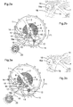
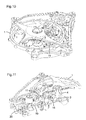
- FIGS. 10 to 13 represent, by way of example, the exhaust device described above mounted in a tourbillon cage whose center of rotation lies on the axis of the blocker 13 and not on the axis of the balance 1.
- Figure 11 is a section of the vortex showing the principle of inverted pivoting of the blocker on a fixed pivot.
- Figure 12 is a top view of the tourbillon cage while Figure 13 is a bottom view where we see the drive of the cage performed by an internal toothing performed on the second fixed wheel 21.
Abstract
Description
La présente invention a pour objet un dispositif d'échappement pour mouvement d'horlogerie, notamment pour montre bracelet ou de poche, le mouvement d'horlogerie pouvant comporter un tourbillon ou non.The subject of the present invention is an escapement device for a watch movement, in particular for a wristwatch or a pocket watch, the clockwork movement possibly comprising a tourbillon or not.
Le but de l'invention est de proposer un dispositif d'échappement de fabrication simple, permettant de diminuer les chocs et les frottements pour augmenter le rendement et de réduire ou supprimer la lubrification du dispositif.The object of the invention is to provide a simple manufacturing exhaust device, to reduce shocks and friction to increase the efficiency and reduce or eliminate the lubrication of the device.
Le dispositif d'échappement selon la présente invention se distingue par les caractéristiques énumérées à la revendication 1.The exhaust system according to the present invention is distinguished by the features listed in
Le dessin annexé illustre schématiquement et à titre d'exemple une forme d'exécution du dispositif d'échappement selon l'invention.
- La figure 1a est une vue en perspective de dessus du dispositif d'échappement.
- La figure 1 b est une vue en perspective de dessous du dispositif d'échappement.
- La figure 2a représente le dispositif d'échappement dans la phase de l'arc supplémentaire dans la période descendante du balancier.
- La figure 2b est un détail à plus grande échelle de la figure 2a.
- La figure 3a représente le dispositif d'échappement dans la phase dite du "coup perdu".
- La figure 3b est un détail à plus grande échelle de la figure 3a.
- La figure 4a illustre le déplacement dans le sens horaire du bloqueur.
- La figure 4b est un détail à plus grande échelle de la figure 4a.
- La figure 5a représente le dispositif d'échappement dans la phase de l'arc supplémentaire dans la phase ascendante qui précède le dégagement.
- La figure 5b est un détail à plus grande échelle de la figure 5a.
- La figure 6a représente le dispositif d'échappement dans la phase de dégagement.
- La figure 6b est un détail à plus grande échelle de la figure 6a.
- La figure 7a représente le dispositif d'échappement entre la phase de dégagement et la phase d'impulsion.
- La figure 7b est un détail à plus grande échelle de la figure 7a.
- La figure 8 représente le dispositif d'échappement dans la phase d'impulsion.
- La figure 9a représente le dispositif d'échappement dans la phase terminale d'impulsion.
- La figure 9b est un détail à plus grande échelle de la figure 9a.
- Les figures 10 à 13 illustrent le dispositif d'échappement monté dans une cage de tourbillon.
- Les figures 14 à 17 illustrent les différents sous-ensembles formant les parties constitutives du dispositif d'échappement.
- Figure 1a is a perspective view from above of the exhaust device.
- Figure 1b is a perspective view from below of the exhaust device.
- Figure 2a shows the exhaust device in the phase of the additional arc in the downward period of the balance.
- Figure 2b is a detail on a larger scale of Figure 2a.
- Figure 3a shows the exhaust device in the so-called "lost shot" phase.
- Figure 3b is an enlarged detail of Figure 3a.
- Figure 4a illustrates the clockwise movement of the blocker.
- Figure 4b is an enlarged detail of Figure 4a.
- Figure 5a shows the exhaust device in the phase of the additional arc in the ascending phase preceding the disengagement.
- Figure 5b is an enlarged detail of Figure 5a.
- Figure 6a shows the exhaust device in the disengagement phase.
- Figure 6b is an enlarged detail of Figure 6a.
- Figure 7a shows the exhaust device between the disengagement phase and the pulse phase.
- Figure 7b is an enlarged detail of Figure 7a.
- Figure 8 shows the exhaust device in the pulse phase.
- Figure 9a shows the exhaust device in the terminal pulse phase.
- Figure 9b is an enlarged detail of Figure 9a.
- Figures 10 to 13 illustrate the exhaust device mounted in a vortex cage.
- Figures 14 to 17 illustrate the different subsets forming the constituent parts of the exhaust device.
Le dispositif d'échappement selon l'invention, dans sa forme d'exécution illustrée à titre d'exemple aux figures 1 à 9 du dessin annexé comporte un balancier 1 relié à un axe 3 de pivotement par des bras 2. L'axe de balancier 3 porte un plateau 4 muni d'une levée d'impulsion 5 s'étendant sensiblement radialement et dont l'extrémité déborde de la périphérie du plateau 4.The exhaust device according to the invention, in its embodiment illustrated by way of example in Figures 1 to 9 of the accompanying drawing comprises a
Ce plateau 4 comporte encore à proximité de sa périphérie une goupille de dégagement 6 s'étendant perpendiculairement au plan du plateau 4 en direction opposée au balancier 1.This
Un ressort spiral 7 est fixé par son extrémité intérieure à l'axe de balancier 3 et par son extrémité extérieure 7a à un piton 8 fixé sur un pont ou la platine du mouvement (non illustré) ou sur la cage d'un tourbillon si l'échappement est monté dans un tourbillon. L'axe du balancier 3 est pivoté entre un pont et la platine du mouvement ou entre la cage et un pont d'un tourbillon.A
Le dispositif d'échappement comporte encore une roue d'échappement 11 et son pignon 12 pivoté entre la platine et un pont du mouvement et positionné de telle façon que chaque dent de la roue d'échappement 11 puisse être placée sur le chemin de la levée d'impulsion 5 pour donner les impulsions au balancier 1.The exhaust device further comprises an
Le dispositif d'échappement comporte encore un bloqueur 13 pivoté entre la platine du mouvement et un pont étoqueaux 14. Ce bloqueur 13 comporte une levée de dégagement 15 s'étendant en direction du plateau 4 et susceptible d'être actionné par la goupille de dégagement 6 de ce plateau 4.The exhaust device further comprises a
Le bloqueur 13 comporte encore une ellipse de repos 16 présentant la forme générale d'un cylindre muni d'un plat 16a et s'étendant perpendiculairement au plan du bloqueur 13, l'ellipse comprend une première partie ou extrémité s'étendant en direction opposée au balancier et une seconde partie ou extrémité s'étendant en direction du balancier. De préférence, l'ellipse de repos 16 est construite en saphir. Les extrémités de cette ellipse de repos sont pivotées dans des paliers fixes 17, l'un porté par le pont étoqueaux 14 et l'autre par la platine du mouvement. Le pont étoqueaux 14 comporte deux butées 18, 18a permettant de limiter les déplacements angulaires du bloqueur 13.The
Le dispositif d'échappement comporte encore un bras de positionnement 19 dont l'extrémité libre coopère avec la face plane 16a de l'ellipse de repos 16 et plus particulièrement avec la première partie ou extrémité de l'ellipse de repos, pour maintenir le bloqueur 13 en position neutre de repos. Ce bras de positionnement 19 est pivoté sur la platine du mouvement et soumis à l'action d'un ressort de rappel spiral 20 tendant à appliquer son extrémité libre contre la face plane 16a de l'ellipse de repos 16. La force de rappel de ce ressort spiral de rappel 20 est faible, juste suffisante pour replacer le bloqueur 13 dans sa position neutre après qu'il aie été déplacé angulairement par la goupille de dégagement 10 du plateau 4 entrant en contact avec la levée de dégagement 15 du bloqueur lors des oscillations du balancier 1.The exhaust device further comprises a
Les figures 2a et 2b illustrent le dispositif d'échappement à l'instant où le balancier 1 ayant terminé sa course ascendante, inverse son sens de rotation et débute sa course descendante pour laquelle il se déplace dans le sens anti-horaire suivant la flèche F1. Pendant que le balancier 1 décrit l'arc supplémentaire dans la période descendante de l'alternance, la roue d'échappement 11 est arrêtée par une de ses dents qui est appuyée contre la partie cylindrique de l'ellipse de repos 16 du bloqueur 13 et plus particulièrement contre la seconde partie ou extrémité de l'ellipse de repos qui est dans sa position neutre de repos. Le bloqueur 13 est maintenu dans cette position de repos par le bras 19 dont l'extrémité libre est appliquée contre la face plane 16a de l'ellipse de repos 16 du bloqueur 13. Ce bras 19 exerce une pression, la plus faible possible, grâce au spiral 20 fixé sur l'axe de rotation du bras 19. Le couple qu'exerce ce ressort de rappel spiral 20 sur le bras 19 est réglable à l'aide d'un porte-piton mobile sur la platine auquel est fixée l'autre extrémité du ressort 19.Figures 2a and 2b illustrate the exhaust device at the moment when the
La goupille de dégagement 6 est solidaire du balancier 1 grâce à son chassage sur le plateau 4, perpendiculairement à la levée d'impulsion 5 et décalée angulairement par rapport à celle-ci.The
Le balancier 1 se déplace ainsi dans le sens anti-horaire jusqu'à la phase dite du "coup perdu" illustrée aux figures 3a, 3b et 4a, 4b. La goupille de dégagement 6 effleure l'extrémité de la levée de dégagement 15 du bloqueur 13 ce qui provoque un léger déplacement du bloqueur 13 uniquement dans le sens horaire. La roue d'échappement 11 elle, ne subit aucun recul géométrique pendant cette phase du "coup perdu" car elle repose par une de ses dents sur la partie cylindrique de l'ellipse de repos 16 du bloqueur 13 qui est concentrique à l'axe de pivotement du bloqueur 13. Ceci ne provoque qu'un très faible frottement entre une dent de la roue d'échappement 11 et l'ellipse de repos 16 du bloqueur 13.The
Le balancier 1 poursuit sa course descendante puis s'immobilise et commence sa phase ascendante en sens horaire suivant la flèche F2 jusqu'à la position illustrée aux figures 5a et 5b. A ce moment la goupille de dégagement 6 entre en contact avec la levée de dégagement 15 du bloqueur 13 qui s'est repositionné en position de repos sous l'action du bras 19. La goupille de dégagement 6 déplace le bloqueur en sens anti-horaire et simultanément la levée d'impulsion 5 vient se placer sur la trajectoire d'une dent de la roue d'échappement 11. La course dans le sens anti-horaire du bloqueur 13 est stoppée par la butée 18a du pont étoqueaux 14 et à ce moment la dent de la roue d'échappement 11 quitte la paroi cylindrique 16 de l'ellipse de repos 16 qui est donc libérée (figure 6a, 6b et 7a, 7b).The
La roue d'échappement 11 est ainsi libérée grâce à la face plane 16a de l'ellipse de repos 16 du bloqueur. Au même moment une autre dent de la roue d'échappement 11 percute la levée d'impulsion 5 du plateau 4 chassé sur l'axe 3 du balancier 1, (figure 8). Durant l'impulsion le bras 19 du bloqueur 13 repositionne le bloqueur 13 en position de repos neutre pour permettre à la dent suivante, celle qui a donné l'impulsion, de la roue d'échappement 11 de s'arrêter contre la surface périphérique cylindrique de l'ellipse de repos 16 du bloqueur 13.The
L'oscillation ascendante du balancier 1 peut alors se terminer et celui-ci arrive à nouveau dans la position illustrée aux figures 2 et 2a au début d'un nouveau cycle.The upward oscillation of the
En cas de choc et/ou durant la phase du "coup perdu" ou de "l'impulsion" le déplacement angulaire du bloqueur 13 est limité par les butées 18, 18a du pont étoquaux 14 ce qui empêche que le bras 19 ne puisse prendre appui sur la partie cylindrique de la périphérie de l'ellipse de repos 16.In the event of an impact and / or during the phase of the "lost blow" or "momentum", the angular displacement of the
De ce qui précède, on voit que ce dispositif d'échappement est un échappement libre puisqu'il laisse au balancier une liberté entière pour parcourir les arcs supplémentaires aux fonctions de l'échappement. Il s'agit également d'un échappement à impulsion directe car il ne comporte pas de système de transmission d'énergie intermédiaire comme c'est le cas pour les échappements à ancre.From the foregoing, it can be seen that this escapement device is a free escapement since it leaves the balance with complete freedom to traverse the additional arcs with the functions of the escapement. It is also a direct impulse escapement because it does not include an intermediate energy transmission system as is the case for anchor escapements.
Les quatre organes de ce dispositif d'échappement sont :The four bodies of this exhaust system are:
La roue d'échappement 11.The
Le plateau 4, solidaire du balancier 1, avec la palette d'impulsion 5 et la goupille de dégagement 6.The
Le bras 19 du bloqueur, etThe
Le bloqueur 13 et sa levée de dégagement 15.The
L'impulsion donnée par la roue d'échappement 11 est directement transmise au balancier 1. Cela permet de diminuer les chocs et les frottements et de ce fait d'augmenter le rendement. Cet échappement a aussi la particularité de ne transmettre qu'une seule impulsion par cycle complet (deux alternances).The impetus given by the
Il est à noter que la surface périphérique de l'ellipse de repos 16 (et en particulier sa seconde extrémité) pourrait avoir des formes diverses à condition qu'elle comprenne une première portion pour arrêter les dents de la roue d'échappement quand le bloqueur 13 est dans certaines positions et une seconde portion pour libérer les dents de la roue d'échappement quand le bloqueur 13 est dans d'autres positions comme décrit ci-dessus. De préférence, la première portion est arrondie et il est d'autant plus préférable qu'elle soit cylindrique afin que le frottement entre une dent de la roue d'échappement et l'ellipse quand le bloqueur tourne soit très faible. Il est également préférable que la seconde portion de la surface périphérique de l'ellipse de repos 16 soit plate. Bien sûr, la surface périphérique de la première extrémité de l'ellipse doit comprendre une portion (de préférence plate encore une fois) pour coopérer de façon appropriée avec le bras de positionnement 19 de la manière décrite ci-dessus.It should be noted that the peripheral surface of the rest ellipse 16 (and in particular its second end) could have various shapes provided that it comprises a first portion to stop the teeth of the escape wheel when the
Ces particularités font, comme l'expérience l'a démontré sur un prototype, que ce dispositif d'échappement peut fonctionner sans lubrifiant.These features make, as experience has shown on a prototype, that this exhaust system can operate without lubricant.
Les figures 10 à 13 représentent à titre d'exemple, le dispositif d'échappement décrit ci-dessus monté dans une cage de tourbillon dont le centre de rotation se trouve sur l'axe du bloqueur 13 et non pas sur l'axe du balancier 1. La figure 11 est une coupe du tourbillon montrant le principe de pivotement inversé du bloqueur sur un pivot fixe. La figure 12 est une vue de dessus de la cage de tourbillon tandis que la figure 13 est une vue de dessous où l'on voit l'entraînement de la cage effectuée par une denture intérieure exécutée sur la roue de seconde fixe 21.FIGS. 10 to 13 represent, by way of example, the exhaust device described above mounted in a tourbillon cage whose center of rotation lies on the axis of the
Claims (11)
Priority Applications (1)
| Application Number | Priority Date | Filing Date | Title |
|---|---|---|---|
| EP20060005703 EP1837718B1 (en) | 2006-03-21 | 2006-03-21 | Escapement device for a timepiece movement |
Applications Claiming Priority (1)
| Application Number | Priority Date | Filing Date | Title |
|---|---|---|---|
| EP20060005703 EP1837718B1 (en) | 2006-03-21 | 2006-03-21 | Escapement device for a timepiece movement |
Publications (2)
| Publication Number | Publication Date |
|---|---|
| EP1837718A1 true EP1837718A1 (en) | 2007-09-26 |
| EP1837718B1 EP1837718B1 (en) | 2014-05-28 |
Family
ID=37564114
Family Applications (1)
| Application Number | Title | Priority Date | Filing Date |
|---|---|---|---|
| EP20060005703 Not-in-force EP1837718B1 (en) | 2006-03-21 | 2006-03-21 | Escapement device for a timepiece movement |
Country Status (1)
| Country | Link |
|---|---|
| EP (1) | EP1837718B1 (en) |
Cited By (2)
| Publication number | Priority date | Publication date | Assignee | Title |
|---|---|---|---|---|
| JP2010190855A (en) * | 2009-02-20 | 2010-09-02 | Seiko Instruments Inc | Detent escapement, governor/escapement using the same, and timepiece |
| FR3008200A1 (en) * | 2013-07-08 | 2015-01-09 | Daniel Galazzo | EXHAUST FOR WATCHPIECES WITH CAGE-FREE TOURBILLON |
Citations (5)
| Publication number | Priority date | Publication date | Assignee | Title |
|---|---|---|---|---|
| US172165A (en) * | 1876-01-11 | Improvement in chronometer-escapements for watches | ||
| CH258A (en) * | 1888-12-27 | 1889-02-20 | Clemence Freres | Advanced detent escapement |
| CH26017A (en) * | 1902-04-12 | 1903-07-15 | Krupp Gmbh | Device on guns for transferring ammunition from an ammunition wagon into the gun's loading ax |
| CH58715A (en) * | 1912-01-25 | 1913-04-01 | Theodore Jequier | Escapement for pendulum timepieces |
| EP0018796A2 (en) * | 1979-04-30 | 1980-11-12 | George Daniels | Watches, clocks and chronometers and escapements therefor |
-
2006
- 2006-03-21 EP EP20060005703 patent/EP1837718B1/en not_active Not-in-force
Patent Citations (5)
| Publication number | Priority date | Publication date | Assignee | Title |
|---|---|---|---|---|
| US172165A (en) * | 1876-01-11 | Improvement in chronometer-escapements for watches | ||
| CH258A (en) * | 1888-12-27 | 1889-02-20 | Clemence Freres | Advanced detent escapement |
| CH26017A (en) * | 1902-04-12 | 1903-07-15 | Krupp Gmbh | Device on guns for transferring ammunition from an ammunition wagon into the gun's loading ax |
| CH58715A (en) * | 1912-01-25 | 1913-04-01 | Theodore Jequier | Escapement for pendulum timepieces |
| EP0018796A2 (en) * | 1979-04-30 | 1980-11-12 | George Daniels | Watches, clocks and chronometers and escapements therefor |
Non-Patent Citations (1)
| Title |
|---|
| BREGUET A-L: "2001 : L'ANNEE DU TOURBILLON", LA FRANCE HORLOGERE, SOCIETE MILLOT ET CIE. BESANCON, FR, no. 621, 1 March 2001 (2001-03-01), pages 56 - 57, XP001003398, ISSN: 0015-9573 * |
Cited By (3)
| Publication number | Priority date | Publication date | Assignee | Title |
|---|---|---|---|---|
| JP2010190855A (en) * | 2009-02-20 | 2010-09-02 | Seiko Instruments Inc | Detent escapement, governor/escapement using the same, and timepiece |
| FR3008200A1 (en) * | 2013-07-08 | 2015-01-09 | Daniel Galazzo | EXHAUST FOR WATCHPIECES WITH CAGE-FREE TOURBILLON |
| WO2015004336A3 (en) * | 2013-07-08 | 2016-01-14 | Galazzo Daniel | Escapement for a timepiece with a tourbillon without a cage |
Also Published As
| Publication number | Publication date |
|---|---|
| EP1837718B1 (en) | 2014-05-28 |
Similar Documents
| Publication | Publication Date | Title |
|---|---|---|
| EP1967919B1 (en) | Exhaust with tangential impulses | |
| EP1538491B1 (en) | Detent escapement for watches | |
| EP1941326B1 (en) | Detent escapement for a timepiece | |
| EP2105806B1 (en) | Escapement mechanism | |
| EP2487546B1 (en) | High-performance bi-axial escapement, or HPBE | |
| EP2224292B1 (en) | Detent escapement for timepiece movement | |
| EP2407830B1 (en) | Timepiece | |
| EP3121661B1 (en) | Constant-force direct escapement mechanism | |
| EP2607968B1 (en) | Escapement mechanism | |
| EP2947522B1 (en) | Timepiece pallet for mechanical oscillator and timer-controlled timepiece trigger mechanism | |
| EP1837718B1 (en) | Escapement device for a timepiece movement | |
| WO2018046563A1 (en) | Escapement mechanism | |
| EP3401739B1 (en) | Timepiece movement comprising a constant force device | |
| CH715052B1 (en) | Constant torque mechanism, timepiece movement, and timepiece. | |
| CH712288B1 (en) | Bi-functional dart, locking and securing device for a timepiece, and watch escapement. | |
| EP3206088A1 (en) | Escapement mechanism | |
| EP3475765B1 (en) | Clock escapement | |
| WO2019201976A1 (en) | Escapement mechanism with a rest lever and timepiece provided with such an escapement mechanism | |
| EP4198641A1 (en) | Natural escapement for timepiece movement and timepiece movement comprising such an escapement | |
| EP4250019A1 (en) | Timepiece oscillator for extra-flat movement | |
| CH301862A (en) | Jumping second mechanism. | |
| CH718579B1 (en) | Natural escapement for a clock movement and clock movement comprising such an escapement. | |
| CH348362A (en) | Jumping needle mechanism for timepiece | |
| EP3783444A1 (en) | Timepiece mechanism comprising a locking device | |
| WO2017013611A1 (en) | Escapement mechanism |
Legal Events
| Date | Code | Title | Description |
|---|---|---|---|
| PUAI | Public reference made under article 153(3) epc to a published international application that has entered the european phase |
Free format text: ORIGINAL CODE: 0009012 |
|
| AK | Designated contracting states |
Kind code of ref document: A1 Designated state(s): AT BE BG CH CY CZ DE DK EE ES FI FR GB GR HU IE IS IT LI LT LU LV MC NL PL PT RO SE SI SK TR |
|
| AX | Request for extension of the european patent |
Extension state: AL BA HR MK YU |
|
| 17P | Request for examination filed |
Effective date: 20080223 |
|
| 17Q | First examination report despatched |
Effective date: 20080401 |
|
| AKX | Designation fees paid |
Designated state(s): CH DE FR GB IT LI |
|
| GRAP | Despatch of communication of intention to grant a patent |
Free format text: ORIGINAL CODE: EPIDOSNIGR1 |
|
| INTG | Intention to grant announced |
Effective date: 20140204 |
|
| GRAS | Grant fee paid |
Free format text: ORIGINAL CODE: EPIDOSNIGR3 |
|
| GRAA | (expected) grant |
Free format text: ORIGINAL CODE: 0009210 |
|
| AK | Designated contracting states |
Kind code of ref document: B1 Designated state(s): CH DE FR GB IT LI |
|
| REG | Reference to a national code |
Ref country code: GB Ref legal event code: FG4D Free format text: NOT ENGLISH |
|
| REG | Reference to a national code |
Ref country code: CH Ref legal event code: EP Ref country code: CH Ref legal event code: NV Representative=s name: MICHELI AND CIE SA, CH |
|
| REG | Reference to a national code |
Ref country code: DE Ref legal event code: R096 Ref document number: 602006041731 Country of ref document: DE Effective date: 20140710 |
|
| REG | Reference to a national code |
Ref country code: DE Ref legal event code: R097 Ref document number: 602006041731 Country of ref document: DE |
|
| PLBE | No opposition filed within time limit |
Free format text: ORIGINAL CODE: 0009261 |
|
| STAA | Information on the status of an ep patent application or granted ep patent |
Free format text: STATUS: NO OPPOSITION FILED WITHIN TIME LIMIT |
|
| PG25 | Lapsed in a contracting state [announced via postgrant information from national office to epo] |
Ref country code: IT Free format text: LAPSE BECAUSE OF FAILURE TO SUBMIT A TRANSLATION OF THE DESCRIPTION OR TO PAY THE FEE WITHIN THE PRESCRIBED TIME-LIMIT Effective date: 20140528 |
|
| 26N | No opposition filed |
Effective date: 20150303 |
|
| REG | Reference to a national code |
Ref country code: DE Ref legal event code: R097 Ref document number: 602006041731 Country of ref document: DE Effective date: 20150303 |
|
| REG | Reference to a national code |
Ref country code: DE Ref legal event code: R119 Ref document number: 602006041731 Country of ref document: DE |
|
| GBPC | Gb: european patent ceased through non-payment of renewal fee |
Effective date: 20150321 |
|
| REG | Reference to a national code |
Ref country code: FR Ref legal event code: ST Effective date: 20151130 |
|
| PG25 | Lapsed in a contracting state [announced via postgrant information from national office to epo] |
Ref country code: DE Free format text: LAPSE BECAUSE OF NON-PAYMENT OF DUE FEES Effective date: 20151001 Ref country code: GB Free format text: LAPSE BECAUSE OF NON-PAYMENT OF DUE FEES Effective date: 20150321 |
|
| PG25 | Lapsed in a contracting state [announced via postgrant information from national office to epo] |
Ref country code: FR Free format text: LAPSE BECAUSE OF NON-PAYMENT OF DUE FEES Effective date: 20150331 |
|
| PGFP | Annual fee paid to national office [announced via postgrant information from national office to epo] |
Ref country code: CH Payment date: 20160323 Year of fee payment: 11 |
|
| REG | Reference to a national code |
Ref country code: CH Ref legal event code: PL |
|
| PG25 | Lapsed in a contracting state [announced via postgrant information from national office to epo] |
Ref country code: LI Free format text: LAPSE BECAUSE OF NON-PAYMENT OF DUE FEES Effective date: 20170331 Ref country code: CH Free format text: LAPSE BECAUSE OF NON-PAYMENT OF DUE FEES Effective date: 20170331 |