EP1837652A2 - Chloranalysevorrichtung - Google Patents
Chloranalysevorrichtung Download PDFInfo
- Publication number
- EP1837652A2 EP1837652A2 EP07004808A EP07004808A EP1837652A2 EP 1837652 A2 EP1837652 A2 EP 1837652A2 EP 07004808 A EP07004808 A EP 07004808A EP 07004808 A EP07004808 A EP 07004808A EP 1837652 A2 EP1837652 A2 EP 1837652A2
- Authority
- EP
- European Patent Office
- Prior art keywords
- tube
- reaction tube
- electric furnace
- deodorization
- insertion hole
- Prior art date
- Legal status (The legal status is an assumption and is not a legal conclusion. Google has not performed a legal analysis and makes no representation as to the accuracy of the status listed.)
- Granted
Links
Images

Classifications
-
- G—PHYSICS
- G01—MEASURING; TESTING
- G01N—INVESTIGATING OR ANALYSING MATERIALS BY DETERMINING THEIR CHEMICAL OR PHYSICAL PROPERTIES
- G01N31/00—Investigating or analysing non-biological materials by the use of the chemical methods specified in the subgroup; Apparatus specially adapted for such methods
- G01N31/16—Investigating or analysing non-biological materials by the use of the chemical methods specified in the subgroup; Apparatus specially adapted for such methods using titration
Definitions
- the present invention relates to a chlorine analyzing apparatus, and more particularly, to a chlorine analyzing apparatus for measuring a trace amount of chlorine using a coulometric titration method.
- a trace amount of chorine compounds contained in environmental water such as river water and lake water or waste water discharged from various factories has been measured, for example, by flowing a liquid sample through a column filled with activated carbon to adsorb a chlorine compound contained in the liquid sample into the activated carbon using a chlorine absorber and then subjecting the chlorine compound adsorbed into the activated carbon to coulometric titration using a chlorine analyzer. More specifically, the activated carbon as a sample is filled in a reaction tube, and the reaction tube is fitted into an electric furnace to heat the sample under an oxygen flow, thereby burning the chlorine compound contained in the sample and converting the chlorine compound into hydrogen chloride.
- the thus generated hydrogen chloride is adsorbed in an electrolyte filled in a titration cell and titrated with silver ions coulometrically generated in the titration cell.
- the amount of chlorine can be calculated from a quantity of electricity required for the titration on the basis of Faraday Rule (refer to "Method for Measuring Chlorine (Vertical-type Furnace Coulometry Method)", Dia Instruments Co., Ltd.; [online]; searched on March, 3, 2006; Internet ⁇ http://www.dins.co.jp/dins_j/3sehin/genri/gts300cl.htm>). Meanwhile, acetic acid is used as the electrolyte to be filled in the titration cell.
- An object of the present invention is to provide a chlorine analyzing apparatus for measuring a trace amount of chlorine contained in a sample by subjecting hydrogen chloride generated by heating the sample to coulometric titration in acetic acid as an electrolyte which is capable of surely and efficiently treating a vapor of acetic acid discharged from the titration cell.
- a vapor of acetic acid discharged from a titration cell is decomposed by heat generated from an electric furnace for heating a reaction tube, whereby the vapor of acetic acid can be efficiently treated without increase in a size of the apparatus used therefor.
- a chlorine analyzing apparatus for measuring an amount of chlorine contained in a sample by subjecting hydrogen chloride generated by heating the sample to coulometric titration
- apparatus comprises mainly a reaction tube of a double tube structure comprising an inner tube with an inlet port for air or oxygen for receiving the sample, and an outer tube with a sampling gas outlet port for recovering hydrogen chloride, the reaction tube being capable of allowing a gas to be flowed from the inner tube to the outer tube; an electric furnace having a reaction tube insertion hole into which the reaction tube is fitted, which is equipped with a heater disposed around the reaction tube insertion hole; and a titration cell receiving acetic acid as an electrolyte for subjecting hydrogen chloride withdrawn from the reaction tube to coulometric titration, said apparatus further comprising a deodorization tube disposed on a rear stage side of the titration cell for thermally decomposing a vapor of acetic acid discharged from the titration cell, which
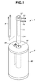
- Fig. 1 is a perspective view showing an electric furnace, a reaction tube and a deodorization tube provided in the chlorine analyzing apparatus of the present invention.
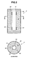
- Fig. 2 is a vertical sectional view and a horizontal sectional view showing a structure of the electric surface provided in the chlorine analyzing apparatus of the present invention.
- Fig. 3 is a flow diagram schematically showing a whole structure of the chlorine analyzing apparatus of the present invention.
- the chlorine analyzing apparatus of the present invention is an analyzer for measuring an amount of chlorine contained in a sample by subjecting hydrogen chloride generated by heating the sample to coulometric titration.
- the chlorine analyzing apparatus generally includes a reaction tube (1) for receiving a sample (P), an electric furnace (9) for heating the reaction tube, and a titration cell (3) for conducting titration of the sample, and in the apparatus, a vapor of acetic acid discharged from the titration cell (3) is decomposed in a deodorization tube (4).
- activated carbon into which a chlorine compound is adsorbed is usually used as the sample (P).
- the reaction tube (1) is a container which serves for not only receiving the above sample (P), but also burning a chlorine compound contained in the sample to recover hydrogen chloride. As shown in Figs. 1 and 3, the reaction tube (1) has a double tube structure constituted of an inner tube (11) for receiving the sample and an outer tube (14) for recovering hydrogen chloride therefrom.
- the inner tube (11) is constituted of an elongated cylindrical tube provided at a head portion thereof with a sample feed portion (12).
- the cylindrical tube of the inner tube (11) is designed so as to have a smaller outer diameter than an inner diameter of the outer tube (14) and a smaller length than a depth of the outer tube (14) in order to ensure a clearance for passing a gas between an outer peripheral surface of the cylindrical tube and an inner peripheral surface of the outer tube (14).
- the inner tube (11) is provided at a lower end thereof with a number of pores for retaining the sample (P) and withdrawing a decomposed gas to thereby render the tube air-permeable.
- the sample feed portion (12) is constituted of a short cylindrical casing having a larger diameter than that of the below-mentioned outer tube (14).
- the casing is provided at an upper end thereof with a lid which is opened and closed to charge the sample (P) thereinto and withdraw the same therefrom.
- the inner tube (11) is provided at a head portion thereof, i.e., at the sample feed portion (12), with an inlet port (13) for introducing air or oxygen for burning the sample thereinto.
- the outer tube (14) is constituted from an elongated bottom-closed cylindrical tube having a smaller diameter than that of the sample feed portion (12) of the above inner tube (11).
- the outer tube (14) is provided at an upper portion thereof with a sampling gas outlet port (15) for withdrawing hydrogen chloride generated by burning the sample.
- the upper end of the outer tube (14) has a threaded portion to which a lower end of the sample feed portion (12) of the inner tube (11) is screw-fitted in a hermetically sealed manner when the inner tube (11) is inserted into the outer tube.
- the reaction tube (1) is constructed such that air or oxygen is fed from the inlet port (13) into the inner tube (11), and hydrogen chloride generated upon burning a chlorine compound contained in the sample (P) is flowed together with an excess amount of air or oxygen into the outer tube (14) and further into the clearance between the outer tube (14) and the inner tube (11), and withdrawn from the sampling gas outlet port (15).
- the inner tube (11) has a diameter of about 20 to 40 mm
- the cylindrical tube of the inner tube (11) has a length of about 350 to 400 mm.
- the outer tube (14) has a diameter of about 30 to 50 mm and a length of about 400 to 450 mm.
- the electric furnace (9) serves as a heating means for heating the reaction tube (1).
- a vapor of acetic acid discharged from the titration cell (3) is passed through a deodorization tube (4) to heat and decompose the acetic acid therein. Therefore, as shown in Fig. 1, the electric furnace is constructed so as to heat the deodorization tube (4) together with the reaction tube (1). More specifically, as shown in Figs. 1 and 2, the electric furnace (9) is provided with a reaction tube insertion hole (91) opened at an upper end of the electric furnace, and heaters (93) are disposed around the reaction tube insertion hole (91). Further, the electric furnace (9) has a deodorization tube insertion hole (94) opened at an upper end thereof in the vicinity of the reaction tube insertion hole (91).
- the electric furnace (9) has such a structure in which a heat insulating material (92) is covered with a casing (90), and a plurality of the heaters (93) are embedded within the heat insulating material (92).
- the heat insulating material (92) there may be used a cylindrical molded product made of ceramic fiber, or a mixed fiber composed of ceramic fiber and alumina fiber.
- the heat insulating material (92) is provided along a central line thereof with the reaction tube insertion hole (91) which is opened at an upper end thereof and has a circular section.
- the deodorization tube insertion hole (94) which is opened at an upper end thereof and has a rectangular section is formed in parallel with the above reaction tube insertion hole (91) and on an outer peripheral side of the heaters (93).
- the heating temperature of the reaction tube (1) is 800 to 1100°C
- the heating temperature of the deodorization tube (4) is 500 to 800°C.
- the deodorization tube insertion hole (94) is formed at such a position located on an outer peripheral side of the heaters (93) and spaced, for example, by about 10 to 20 mm apart from the heaters (93), as shown in Fig. 2.
- the thickness of the heat insulating material (92) (radial distance from a circumferential surface of the reaction tube insertion hole (91) to an outer peripheral surface of the heat insulating material (92)) is about 40 to 50 mm, and a bulk density thereof is about 290 to 350 kg/m 3 when the heat insulating material is made of a ceramic fiber.
- the heaters (93) there may be used, for example, a sheathed heater formed by accommodating a kanthal heat generator, a nichrome heat generator, a silver heat generator, etc., within a metal tube. Such heaters (93) are disposed around the reaction tube insertion hole such that the surface of each heater is exposed to the reaction tube insertion hole (91). Meanwhile, in the chlorine analyzing apparatus of the present invention, ten to twelve heaters (93) are disposed such that a total output power thereof is, for example, 1 kW.
- the temperature of the reaction tube (1) is detected to control an electric current fed to the heaters (93) for keeping the reaction tube (1) at a predetermined temperature.
- the electric furnace (9) is provided with the reaction tube insertion hole (91) opened at an upper end of the electric furnace.
- the reaction tube (1) has the inner tube (11) provided at a head portion thereof with the inlet port (13) for air or oxygen, and the outer tube (14) provided at an upper portion thereof with the sampling gas inlet port (15), and is detachably fitted into the reaction tube insertion hole (91) of the electric furnace (9) from above. Therefore, in the chlorine analyzing apparatus of the present invention, the reaction tube (1) can be extremely readily replaced with new one, resulting in facilitated handling and maintenance. In addition, since an operating space required becomes small, the apparatus of the present invention can be reduced in size.
- a dehydration bath (2) filled, for example, with concentrated sulfuric acid as a dehydrating agent. More specifically, the sampling gas outlet port (15) of the outer tube (14) of the reaction tube (1) is connected to the dehydration bath (2) through a flow path (81).
- the titration cell (3) is disposed at a rear stage of the above dehydration bath (2). More specifically, the dehydration bath (2) is connected to the titration cell (3) through a flow path (82) whose base end is located in a gas phase portion (air space portion) of the dehydration bath. The other tip end of the flow path (82) is immersed in an electrolyte filled in the titration cell (3).
- the titration cell (3) is filled with 70 to 90% acetic acid as the electrolyte, and serves as a device for subjecting hydrogen chloride withdrawn from the reaction tube (1) to coulometric titration.
- the titration cell (3) may be operated by a known mechanism, and is provided therein with a generating electrode, a generating counter electrode, a detection electrode and a reference electrode which are immersed in the electrolyte.
- an electric current for electrolysis flowed between the silver generating electrode and the generating counter electrode is controlled such that a potential of the electrolyte is maintained at a predetermined potential (terminal potential), thereby not only maintaining an equilibrium between (Ag + ) and (e-) but also causing the reaction represented by the formula: HCl + Ag + ⁇ AgCl + H + by introducing hydrogen chloride into the cell.
- the electric current for electrolysis flowed is controlled such that the potential of the electrolyte is returned to the terminal potential, thereby generating silver ions (Ag + ) from the silver generating electrode.
- the titration is terminated to calculate an amount of chlorine from the quantity of electricity required for the titration. Meanwhile, the amount of acetic acid previously filled in the titration cell (3) is 20 to 40 mL.
- a vapor of acetic acid as the electrolyte is generated by the above titration procedure.
- the titration cell (3) is equipped at a discharge port thereof with a cooler (31) for cooling the vapor of acetic acid discharged from the titration cell.
- a cooler (31) there may be used, for example, a coiled condenser constituted of a coiled tube enclosed in a casing for allowing the vapor of acetic acid to pass therethrough.
- the cooler (31) is constructed such that cold water is fed, for example, from a small-size electronic cooler using a Peltier element.
- the Peltier element is an electronic part used as a cooler for electronic devices, and is constituted from two metal plates and a large number of P-type semiconductors and N-type semiconductors disposed between the two metal plates in which one metal plate forms an N-P junction whereas the other metal plate forms a P-N junction.
- the Peltier element when an electric current is flowed through the P-N junction portion, an endothermic phenomenon is caused at the one metal plate.
- At least a part of acetic acid discharged in the form of a vapor from the titration cell (3) can be liquefied and circulated to the titration cell (3), so that the amount of the vapor of acetic acid to be treated in the below-mentioned deodorization tube (4) can be reduced, and reduction in amount of acetic acid as the electrolyte in the titration cell (3) can be prevented.
- the deodorization tube (4) is disposed at a rear stage of the titration cell (3) for decomposing the vapor of acetic acid discharged from the titration cell (3). More specifically, the discharge port of the titration cell (3) is connected to the deodorization tube (4) through the above cooler (31) and a flow path (83). The deodorization tube (4) is fitted into the deodorization tube insertion hole (94) of the electric furnace (9) so as to thermally decompose the vapor of acetic acid.
- the deodorization tube (4) is constituted of a U-shaped tube provided at an upper end thereof with a gas inlet port (pipe joint) and a gas outlet port (pipe joint).
- the deodorization tube insertion hole (94) is opened at an upper end of the electric furnace (9) as described above, so that the deodorization tube (4) is fitted into the deodorization tube insertion hole (94) from above. Therefore, in the chlorine analyzing apparatus of the present invention, maintenance and control of the deodorization tube (4) can be extremely readily performed. In addition, since a space required for operation of the deodorization tube (4) is small, the apparatus can be reduced in size.
- the deodorization tube (4) is filled with a heat-resistant filler such as a metal oxide catalyst in order to prolong the time required for allowing the vapor of acetic acid discharged from the titration (3) to pass therethrough and thereby ensure thermal decomposition thereof.
- the deodorization tube (4) usually has a diameter of about 4 to 8 mm and a length of about 200 to 400 mm.
- the amount of the filler filled in the deodorization tube (4) may be controlled to about 0.2 to 2 g.
- a dehydration bath (5) for dehydration and gas-washing there are disposed a dehydration bath (5) for dehydration and gas-washing, a dryer (6) for separating water using a hollow yarn membrane and a removing device (7) constituted, for example, from alkali-supporting diatomaceous earth.
- a gas discharge port of the deodorization tube (4) is connected to the dehydration bath (5) through a flow path (84), and the dehydration bath (5) is connected at a rear stage thereof to the dryer (6) through a flow path (85). Further, the dryer (6) is connected at a rear stage thereof to the removing device (7) through a flow path (86).
- the removing device (7) located at a most downstream side of the system may be further connected to a vacuum pump (8) such as a rotary pump through a flow path (87) equipped with a flow control needle valve.
- activated carbon in which a chlorine compound is adsorbed, i.e., the sample (P) is first charged into the inner tube (11) of the reaction tube (1).
- the amount of the sample (P) to be charged is usually about 0.02 to 0.1 g.
- air or oxygen is fed into the inner tube (11) of the reaction tube (1) through the inlet port (13) for air or oxygen.
- the air or oxygen is fed in a constant amount under a constant pressure through a flow path (not shown) equipped with a pressure reducing valve and a flow control valve from a container in which air or oxygen is filled in a compressed state. Specifically, the air or oxygen is fed under a pressure of 1 to 3 MPa at a flow rate of 1 to 2 L/min.
- the electric furnace is energized such that an inside of the reaction tube (1) is heated to a temperature of 800 to 1100°C by the heaters (93).
- the chlorine compound contained in the sample (P) filled in the inner tube (11) is burned under an air or oxygen gas flow to produce hydrogen chloride.
- the thus generated hydrogen chloride is flowed together with an excess amount of air or oxygen into the outer tube (14) and then into the clearance between the outer tube (14) and the inner tube (11), and finally withdrawn through the sampling gas outlet port (15) of the outer tube (14).
- the hydrogen chloride thus obtained in the reaction tube (1) is delivered to the dehydration bath (2) where the gas is subjected to dehydration treatment, and then introduced into the titration cell (3).
- the hydrogen chloride is blown into acetic acid as the electrolyte and subjected to coulometric titration by the above-described method.
- a quantity of an electric current flowed through the electrode during the titration is measured, and an amount of chlorine is calculated from the measured value using a computer separately provided.
- the result of the titration is expressed by the value as measured in terms of chlorine.
- the vacuum pump (8) is simultaneously operated. While feeding air or oxygen to the reaction tube (1) and conducting the titration procedure in the titration cell (3), a part of the vapor of acetic acid discharged from the titration cell (3) is captured by the cooler (31) and circulated to the titration cell (3). The other part of the vapor of acetic acid is introduced into the deodorization tube (4) through the flow path (83) and subjected to decomposition treatment in the deodorization tube (4).
- the deodorization tube (4) is accommodated in the electric furnace (9) as described above, the deodorization tube (4) is heated to a temperature of not less than 440°C and preferably 600 to 800°C, so that the vapor of acetic acid fed thereto is thermally decomposed, and carbon dioxide gas and water are discharged from the deodorization tube (4).
- the carbon dioxide gas and water discharged from the deodorization tube (4) are then delivered to the dehydration bath (5) and the dryer (6) to remove water therefrom, and then delivered to the removing device (7) to render the discharged gas harmless.
- the deodorization tube (4) since the deodorization tube (4) is accommodated within the electric furnace (9) for heating the reaction tube, the deodorization tube (4) can be heated by utilizing heat generated from the electric furnace (9), so that the vapor of acetic acid discharged from the titration cell (3) can be thermally decomposed.
- the vapor of acetic acid since the vapor of acetic acid is surely treated, it is possible to prevent malodor from being released from the apparatus.
- provision of a separate heating means is not required, the treatment can be surely and efficiently conducted without increase in size of the apparatus.
- the deodorization tube since the deodorization tube is accommodated within the electric furnace for heating the reaction tube, the deodorization tube can be heated by utilizing heat generated from the electric furnace to thermally decompose the vapor of acetic acid discharged from the titration cell. As a result, the vapor of acetic acid can be surely treated without increase in size of the apparatus.
Landscapes
- Health & Medical Sciences (AREA)
- Life Sciences & Earth Sciences (AREA)
- Molecular Biology (AREA)
- Physics & Mathematics (AREA)
- Chemical & Material Sciences (AREA)
- Analytical Chemistry (AREA)
- Biochemistry (AREA)
- General Health & Medical Sciences (AREA)
- General Physics & Mathematics (AREA)
- Immunology (AREA)
- Pathology (AREA)
- Investigating Or Analyzing Non-Biological Materials By The Use Of Chemical Means (AREA)
Applications Claiming Priority (2)
| Application Number | Priority Date | Filing Date | Title |
|---|---|---|---|
| JP2006078066 | 2006-03-22 | ||
| JP2006310156A JP4816420B2 (ja) | 2006-03-22 | 2006-11-16 | 塩素分析装置 |
Publications (3)
| Publication Number | Publication Date |
|---|---|
| EP1837652A2 true EP1837652A2 (de) | 2007-09-26 |
| EP1837652A3 EP1837652A3 (de) | 2010-07-14 |
| EP1837652B1 EP1837652B1 (de) | 2012-02-22 |
Family
ID=38181364
Family Applications (1)
| Application Number | Title | Priority Date | Filing Date |
|---|---|---|---|
| EP07004808A Active EP1837652B1 (de) | 2006-03-22 | 2007-03-08 | Chloranalysevorrichtung |
Country Status (3)
| Country | Link |
|---|---|
| US (1) | US7968053B2 (de) |
| EP (1) | EP1837652B1 (de) |
| JP (1) | JP4816420B2 (de) |
Cited By (2)
| Publication number | Priority date | Publication date | Assignee | Title |
|---|---|---|---|---|
| CN111766330A (zh) * | 2020-06-30 | 2020-10-13 | 南京三鸣智自动化工程有限公司 | 一种气体的检测装置及检测方法 |
| EP4202430A1 (de) | 2021-12-23 | 2023-06-28 | Analytik Jena GmbH | Messsystem |
Families Citing this family (4)
| Publication number | Priority date | Publication date | Assignee | Title |
|---|---|---|---|---|
| CN103399074B (zh) * | 2013-07-29 | 2015-05-13 | 中国石油化工股份有限公司 | 一种测定微量总硫和总氯的石英管装置 |
| JP6748366B2 (ja) * | 2018-08-13 | 2020-09-02 | 東亜ディーケーケー株式会社 | 滴定装置及び滴定管の洗浄方法 |
| JP7365581B2 (ja) * | 2020-02-27 | 2023-10-20 | 三菱マテリアル株式会社 | 塩素含有灰の塩素濃度の測定方法 |
| US20240125730A1 (en) * | 2022-10-18 | 2024-04-18 | Eci Technology, Inc. | Non-reagent chloride analysis in acid copper plating baths |
Family Cites Families (12)
| Publication number | Priority date | Publication date | Assignee | Title |
|---|---|---|---|---|
| US2856426A (en) * | 1955-01-12 | 1958-10-14 | Canadian Celanese Ltd | Thermal decomposition of acetic acid |
| JPS58162854A (ja) | 1982-03-24 | 1983-09-27 | Mitsubishi Chem Ind Ltd | ハロゲンの定量法 |
| JPS61194358A (ja) * | 1985-02-22 | 1986-08-28 | Shin Etsu Chem Co Ltd | アンモニア中の水分及び酸素分を測定する装置 |
| JPS61283865A (ja) * | 1985-06-10 | 1986-12-13 | Mitsubishi Chem Ind Ltd | ハロゲンの定量法 |
| JPH0715468B2 (ja) * | 1986-04-09 | 1995-02-22 | 三菱化学株式会社 | ハロゲンの定量法 |
| DE3612539A1 (de) * | 1986-04-14 | 1987-10-15 | Huels Chemische Werke Ag | Verfahren zur herstellung von technisch reinem, chlorfreiem cyclohexadecadien |
| JP2703513B2 (ja) * | 1995-03-02 | 1998-01-26 | 株式会社環境工学研究所 | 有機物高速分解乾燥処理装置 |
| JPH11155560A (ja) * | 1997-11-25 | 1999-06-15 | Hitachi Zosen Corp | 有機物分解性微生物およびこれを用いる脱臭法 |
| JP2002177371A (ja) * | 2000-12-19 | 2002-06-25 | Hitachi Hometec Ltd | 脱臭装置 |
| JP2003126228A (ja) * | 2001-10-29 | 2003-05-07 | Kogi Corp | 脱臭装置 |
| JP3977218B2 (ja) | 2002-09-30 | 2007-09-19 | 株式会社ダイアインスツルメンツ | 試料加熱装置 |
| JP4051486B2 (ja) * | 2005-07-11 | 2008-02-27 | バイオエンジニアリング・リソーシズ・インコーポレーテツド | 一酸化炭素の嫌気性発酵 |
-
2006
- 2006-11-16 JP JP2006310156A patent/JP4816420B2/ja active Active
-
2007
- 2007-03-01 US US11/712,551 patent/US7968053B2/en active Active
- 2007-03-08 EP EP07004808A patent/EP1837652B1/de active Active
Cited By (4)
| Publication number | Priority date | Publication date | Assignee | Title |
|---|---|---|---|---|
| CN111766330A (zh) * | 2020-06-30 | 2020-10-13 | 南京三鸣智自动化工程有限公司 | 一种气体的检测装置及检测方法 |
| CN111766330B (zh) * | 2020-06-30 | 2022-04-19 | 南京三鸣智自动化工程有限公司 | 一种气体的检测装置及检测方法 |
| EP4202430A1 (de) | 2021-12-23 | 2023-06-28 | Analytik Jena GmbH | Messsystem |
| DE102021134602A1 (de) | 2021-12-23 | 2023-06-29 | Analytik Jena Gmbh | Messsystem |
Also Published As
| Publication number | Publication date |
|---|---|
| US20070224086A1 (en) | 2007-09-27 |
| EP1837652A3 (de) | 2010-07-14 |
| US7968053B2 (en) | 2011-06-28 |
| JP4816420B2 (ja) | 2011-11-16 |
| JP2007286032A (ja) | 2007-11-01 |
| EP1837652B1 (de) | 2012-02-22 |
Similar Documents
| Publication | Publication Date | Title |
|---|---|---|
| US7968053B2 (en) | Chlorine analyzing apparatus | |
| JP4211915B2 (ja) | プラズマ酸化を使用する広範囲の全有機炭素含量測定装置 | |
| KR101587559B1 (ko) | 연소산화방식 총유기탄소 측정장치 및 상기 측정장치를 이용한 연소산화방식 총유기탄소 측정방법 | |
| JP2009526235A (ja) | 全有機炭素分析 | |
| CN118575078A (zh) | 使用总有机氟化物检测全氟和多氟烷基物质 | |
| EP1403636B1 (de) | Probenheizvorrichtung | |
| JPH0985044A (ja) | 酸化物ガス処理方法とその装置 | |
| JP4811221B2 (ja) | 分析装置 | |
| JP2008304139A (ja) | 気化装置並びにそれを備える発電装置及び電子機器 | |
| JP2018091809A (ja) | 地熱発電用蒸気性状監視装置、地熱発電システム、地熱発電用蒸気性状監視方法、及び、地熱発電システム制御方法 | |
| JPS60187854A (ja) | 酸素濃度測定装置 | |
| JP6128523B2 (ja) | 水溶性セレンの化学発光分析方法 | |
| JP4779911B2 (ja) | 分析装置 | |
| Chernenko et al. | Catalytic oxidation of acetone and ethanol on a platinum wire | |
| JP4821646B2 (ja) | 吸着性有機ハロゲン分析方法 | |
| CN112782150A (zh) | 一种用于液体阴极辉光放电光谱仪的进样系统 | |
| JP6260433B2 (ja) | 窒素の分析方法 | |
| JP2005147683A (ja) | 試料前処理装置 | |
| KR101176874B1 (ko) | 석유화학 폐기물의 열분해 장치 및 방법 | |
| JP5681357B2 (ja) | マイクロ波非平衡プラズマを用いた有機物質の処理方法 | |
| CN110361470A (zh) | 测定水中总有机卤含量的放电等离子体-离子色谱方法 | |
| JP2012137381A (ja) | 窒素分析用試料の処理方法および処理装置 | |
| JPS6175281A (ja) | トリチウム濃度測定法 | |
| KR820000085B1 (ko) | 고온 기준 전극 | |
| JP2025111322A (ja) | ガス処理装置及びガス処理方法 |
Legal Events
| Date | Code | Title | Description |
|---|---|---|---|
| PUAI | Public reference made under article 153(3) epc to a published international application that has entered the european phase |
Free format text: ORIGINAL CODE: 0009012 |
|
| AK | Designated contracting states |
Kind code of ref document: A2 Designated state(s): AT BE BG CH CY CZ DE DK EE ES FI FR GB GR HU IE IS IT LI LT LU LV MC MT NL PL PT RO SE SI SK TR |
|
| AX | Request for extension of the european patent |
Extension state: AL BA HR MK YU |
|
| RAP1 | Party data changed (applicant data changed or rights of an application transferred) |
Owner name: MITSUBISHI CHEMICAL ANALYTECH CO., LTD. |
|
| PUAL | Search report despatched |
Free format text: ORIGINAL CODE: 0009013 |
|
| AK | Designated contracting states |
Kind code of ref document: A3 Designated state(s): AT BE BG CH CY CZ DE DK EE ES FI FR GB GR HU IE IS IT LI LT LU LV MC MT NL PL PT RO SE SI SK TR |
|
| AX | Request for extension of the european patent |
Extension state: AL BA HR MK RS |
|
| 17P | Request for examination filed |
Effective date: 20110112 |
|
| AKX | Designation fees paid |
Designated state(s): DE FR GB IT |
|
| GRAP | Despatch of communication of intention to grant a patent |
Free format text: ORIGINAL CODE: EPIDOSNIGR1 |
|
| GRAS | Grant fee paid |
Free format text: ORIGINAL CODE: EPIDOSNIGR3 |
|
| GRAA | (expected) grant |
Free format text: ORIGINAL CODE: 0009210 |
|
| RIN1 | Information on inventor provided before grant (corrected) |
Inventor name: TAMAKI, TOMOYOSE Inventor name: HAYASHI, NORIO Inventor name: AKASAKA, SHUICHI Inventor name: OKAFUJI, TAKAYUKI |
|
| AK | Designated contracting states |
Kind code of ref document: B1 Designated state(s): DE FR GB IT |
|
| REG | Reference to a national code |
Ref country code: GB Ref legal event code: FG4D |
|
| REG | Reference to a national code |
Ref country code: DE Ref legal event code: R096 Ref document number: 602007020783 Country of ref document: DE Effective date: 20120419 |
|
| PG25 | Lapsed in a contracting state [announced via postgrant information from national office to epo] |
Ref country code: IT Free format text: LAPSE BECAUSE OF FAILURE TO SUBMIT A TRANSLATION OF THE DESCRIPTION OR TO PAY THE FEE WITHIN THE PRESCRIBED TIME-LIMIT Effective date: 20120222 |
|
| PLBE | No opposition filed within time limit |
Free format text: ORIGINAL CODE: 0009261 |
|
| STAA | Information on the status of an ep patent application or granted ep patent |
Free format text: STATUS: NO OPPOSITION FILED WITHIN TIME LIMIT |
|
| 26N | No opposition filed |
Effective date: 20121123 |
|
| REG | Reference to a national code |
Ref country code: DE Ref legal event code: R097 Ref document number: 602007020783 Country of ref document: DE Effective date: 20121123 |
|
| REG | Reference to a national code |
Ref country code: FR Ref legal event code: PLFP Year of fee payment: 10 |
|
| REG | Reference to a national code |
Ref country code: FR Ref legal event code: PLFP Year of fee payment: 11 |
|
| REG | Reference to a national code |
Ref country code: FR Ref legal event code: PLFP Year of fee payment: 12 |
|
| PGFP | Annual fee paid to national office [announced via postgrant information from national office to epo] |
Ref country code: DE Payment date: 20250319 Year of fee payment: 19 |
|
| PGFP | Annual fee paid to national office [announced via postgrant information from national office to epo] |
Ref country code: FR Payment date: 20250325 Year of fee payment: 19 |
|
| PGFP | Annual fee paid to national office [announced via postgrant information from national office to epo] |
Ref country code: GB Payment date: 20250321 Year of fee payment: 19 |